Contents
- 1. McM G4 User manual
- 2. Pains Wessex SOS Precision User Manual
McM G4 User manual
OWNERS MANUAL
VRV 3
4
22
11
5

1
1 Warnings................................................................................................................ 2
2 Introduction........................................................................................................... 3
2.1 COSPAS-SARSAT satellite system ...............................................................................3
2.2 Global Positioning System (GPS) ..................................................................................4
3 Purpose.................................................................................................................. 5
4 Description ............................................................................................................ 6
4.1 Wall bracket...................................................................................................................6
4.2 Float-free enclosure.......................................................................................................7
4.3 Manual G4 in enclosure .................................................................................................8
5 Controls ................................................................................................................. 9
5.1 ON button ......................................................................................................................9
5.2 READY button................................................................................................................9
5.3 Sea switch .....................................................................................................................9
5.4 Lamps..........................................................................................................................10
6 Operating procedure .......................................................................................... 11
6.1 Sinking.........................................................................................................................11
6.2 Abandon ship...............................................................................................................11
6.3 Releasing G4 from a wall bracket.................................................................................11
6.4 Releasing G4 from an enclosure..................................................................................12
6.5 Manual activation.........................................................................................................12
6.6 Deactivation.................................................................................................................13
6.7 Battery condition ..........................................................................................................13
6.8 Re-fitting G4.................................................................................................................13
7 False alarms ........................................................................................................ 15
7.1 Stand down rescue services ........................................................................................15
7.2 De-activate the EPIRB .................................................................................................15
7.3 Dealing with a transmitting G4 .....................................................................................16
8 Wall bracket installation..................................................................................... 17
8.1 Siting............................................................................................................................17
8.2 Mounting procedure .....................................................................................................17
8.3 Mounting instruction plate ............................................................................................18
9 Enclosure installation......................................................................................... 19
9.1 Siting............................................................................................................................19
9.2 Mounting procedure .....................................................................................................19
9.3 Mounting instruction plate ............................................................................................20
9.4 Marking HRU expiry .....................................................................................................20
9.5 Marking vessel name ...................................................................................................21
10 Registration......................................................................................................... 22
10.1 Overview..................................................................................................................22
10.2 How to register.........................................................................................................22
10.3 Warranty form ..........................................................................................................22
10.4 Radio licence ...........................................................................................................23
10.5 Sale or transfer ........................................................................................................23
11 Maintenance ........................................................................................................ 24
11.1 Monthly self-test & inspection...................................................................................24
11.2 HRU replacement.....................................................................................................25
11.3 Battery replacement.................................................................................................26
11.4 Servicing..................................................................................................................26
11.5 Transportation..........................................................................................................26
11.6 GMDSS inspections.................................................................................................26
12 Fully disabling a G4............................................................................................ 27
13 Technical specification ...................................................................................... 28

2
1 WARNINGS
• This EPIRB is an emergency device for use only in grave
and imminent danger.
• False alarms cost lives and money. Help to prevent them;
understand how to activate and disable your equipment.
• Read the complete manual before installing, testing or
using the EPIRB.
• Ensure the EPIRB is registered with your local authorities
(Flag State nation).
• The EPIRB contains no user servicable parts. Return to
your dealer for battery replacement or other service. Do
not open.
• Dispose of this device safely. Contents include Lithium
batteries; do not incinerate, puncture, deform or short-
circuit.
• This device emits radio frequency radiation when
activated. Because of the levels and duty cycles, such
radiation is not classed as harmful.
• Do not stare at strobe.

3
2 INTRODUCTION
2.1 COSPAS-SARSAT satellite system
The COSPAS-SARSAT system provides distress alert and location information to
search and rescue authorities anywhere in the world for maritime, aviation and
terrestrial users in distress.
There are two satellite arrays carrying the COSPAS-SARSAT system. The principal
array is LEOSAR (Low Earth Orbit Search and Rescue) which has seven satellites in
polar and near-polar orbits. The orbits of these satellites are arranged to scan the
entire surface of the Earth; on average, a satellite comes into view every 45 minutes.
Distress transmissions from EPIRBs are picked up by the satellites and retransmitted
to ground receiving stations, which then pass the message to the appropriate rescue
organisation. On average, the total delay from activation of an EPIRB to the message
being received by the rescue services is 90 minutes.
COSPAS-SARSAT is in an advanced stage of commissioning the second satellite
array, GEOSAR (Geostationary Search and Rescue). This array uses geostationary
satellites which are always in view (over their area of coverage), so that reception of
the EPIRB signal is instantaneous.
LEOSAR satellite path and scan footprint
GEOSAR coverage
4
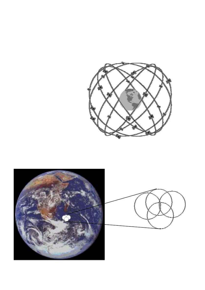
2.2 Global Positioning System (GPS)
The GPS system is a satellite array which enables a receiver located anywhere on
Earth to determine its exact position, usually to within 100m.
The array uses 24 satellites (plus spares) orbiting the Earth in six orbital planes, four
satellites per plane, as shown below. These are arranged so that at least five satellites
are within range of any receiver (which can be anywhere) at all times.
Each satellite transmits information which enables its position and distance from the
receiver to be calculated. By combining these data for multiple satellites, the exact
position of the receiver can be determined.
GPS satellite orbital planes
Operation of GPS receiver
(
size exaggerated for clarity)
5
3 PURPOSE
An Emergency Position Indicating Radio Beacon (EPIRB) is used to alert search and
rescue services in the event of an emergency. It does this by transmitting a coded
message on the 406MHz distress frequency. This message is relayed via satellite and
earth station to the nearest rescue co-ordination centre.
The satellite system is run by COSPAS-SARSAT, and has already been described.
With the geostationary satellite section being commissioned, the alerting delay is
reduced from typically 90 minutes to a few minutes within the geostationary satellite
coverage.
Instant alerting is good news, but they still need to know where you are. The
advantage of the G4 EPIRB is that it has a built in GPS receiver, so within minutes of
activation it will have determined your latitude / longitude coordinates and will have
transmitted these to the rescue centre. The position fix is accurate to 150m*.
To operate properly the G4 needs a clear view of the whole sky. If its view is blocked
and it is unable to get a position fix, then the system defaults to using a polar orbiting
satellite to determine position. In this case, there is typically a 45 minute delay before
the position is known and the accuracy is limited to within 5km (3 miles). This is the
original system that standard (non-GPS) EPIRBs use. To get the full advantage of the
G4 it is important to give it a clear view of the whole sky.
The G4 transmits a message that identifies the exact vessel to which it was registered.
Knowing which vessel is in distress allows the rescue services to eliminate false
alarms and launch an appropriate rescue.
The G4 also has a secondary distress transmitter. This transmits on 121.5MHz and is
used for “homing” purposes. When the rescue services get close, this allows them to
direction find on the signal. To cater for searches at night, the G4 has a bright flashing
light that aids final visual location.
S
E
A
L
READY
TEST
PRESS TO
Antenna
Strobe
Green lamp
Program point
Sea contacts
Lanyard
ON button
under here
READY
button
Battery expiry date
Red lamp
* If the programmed identity
is a Radio Call Sign (RCS)
then accuracy is limited to 5km

6
4 DESCRIPTION
The G4 is a powerful self-contained distress transmitter. It is powered by a light weight
Lithium battery that has a replacement interval of 5 years. An EPIRB is intended to be
a one-shot device; once activated it can operate for at least 48 hours. It operates best
while floating in water, but it can also be operated while on board or in a liferaft.
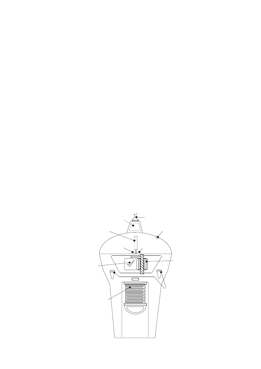
Refering to the previous figure, the key components of your G4 are as follows:
Antenna This is a flexible whip. It must be near vertical when
operating.
If the antenna gets bent, gently straighten it out.
Strobe light This is the glass U-tube visible through the clear lens dome.
When the G4 is activated this will flash every few seconds.
Red lamp Visible through the clear lens dome at the rear of the G4.
This stays on or flashes to show you which mode you are
in.
Green lamp This flashes when the GPS gets a position fix.
Program point A dimple in the clear dome, through which your supplier can
optically input the coded message unique to your G4.
You must register the coded message with local
authorities.
READY button Press this key once to de-activate the G4. Hold it down to
run the built-in self-test, which checks basic operation.
ON button Press this key to activate the G4 manually. The key is
protected by a sliding door which is fitted with a tamper
seal.
Sea switch The two screw heads below the keys are sea switch
contacts. Submerge these in water to automatically activate
the G4.
Lanyard Pull the lanyard spool down to free it. Use the cord to tether
the G4 to a survival craft.
Never tie the G4 to your vessel.
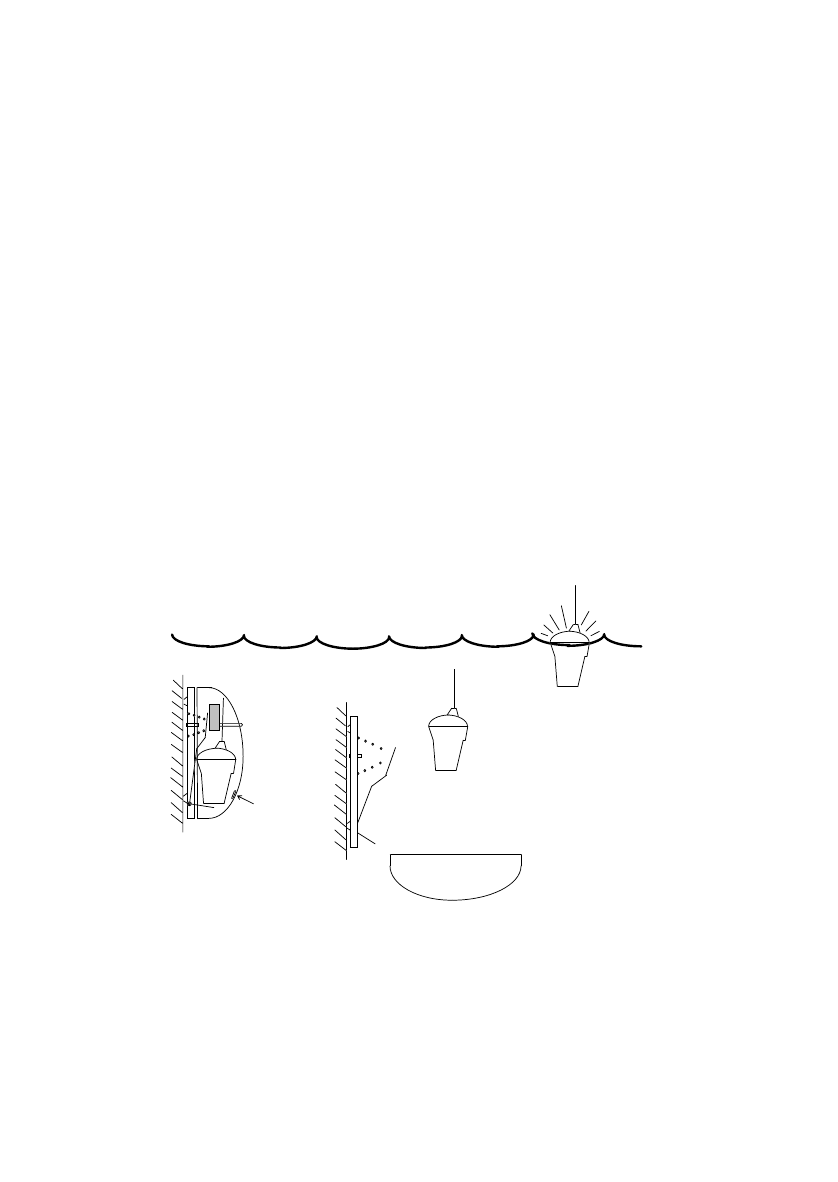
4.1 Wall bracket
If you purchased the manually activated version (G4m), this is normally supplied with a
wall mounting bracket (see section 8). The bracket is made from white plastic so it will
not rust. Its top section is sprung loaded, so that one simple squeeze will quickly
release the G4 allowing it to be carried to a liferaft. The wall bracket should be sited in
plain view near an emergency exit. This bracket is more than just a stowage point, it
contains a magnet which disarms the G4’s sea switch. If you do not stow the G4 in its
bracket, there is a risk of the G4 activating if it gets wet.
7
4.2 Float-free enclosure
If you purchased the automatically activated version (G4a), also known as the “float-
free” version, then your G4 is supplied in a plastic enclosure (see section 9). This is
much more than just a protective housing, it contains a sprung loaded lever which
automatically pushes the enclosure lid off and releases the G4 if your vessel sinks.
This automatic ejection is controlled by a device called a Hydrostatic Release Unit
(HRU). If the enclosure is submerged then before it reaches 4 metres (13 feet) deep
the HRU cuts a plastic rod that holds back the spring and the lid is ejected, releasing
the EPIRB which floats to the surface and switches on automatically.
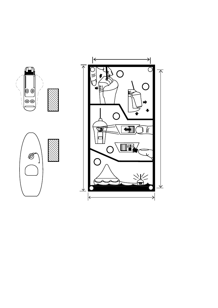
The diagram below illustrates the automatic release sequence:
1. As the vessel sinks, the enclosure fills with water. The HRU contains a
blade which is released due to water pressure acting on a diaphragm.
Before it reaches a depth of 4 metres, the HRU will operate and cut the
plastic rod, releasing the coil spring.
2. The spring pushes the G4 and the enclosure lid outwards. As the lid
pivots off it disengages from the screw head that helped hold it in place.
The lid is weighted so it rolls over and falls away.
3. As the G4 floats away from the lid, it moves out of range of the magnet.
Once away from the magnet its sea switch becomes armed.
4. The sea switch activates. The EPIRB then floats on the surface with its
strobe light flashing. After 3 minutes it makes its first distress
transmission.
If you need to activate your G4 manually, it can be freed from the enclosure after
pulling out the R-shaped retaining pin and removing the lid.
H
R
U
1) HRU cuts rod
2) Lid ejects
4) sea switch
activates
3) EPIRB arms once
away from magnet
Magnet

8
4.3 Manual G4 in enclosure
Customers who need to mount their G4 in an exposed position can select the
protective enclosure without an HRU fitted (G4c). This means that the G4 will not float
free if your vessel sinks. This is known as a category 2 EPIRB. You can tell which
enclosure you have by reading the category from the front of the enclosure:
G4a Category 1 HRU fitted Automatic float-free
G4c Category 2 No HRU fitted Will not float free
9
5 CONTROLS
5.1 ON button
This is hidden behind a sliding door, which protects it from accidental activation. The
sliding door has a tamper seal to show if the G4 has been activated.
The G4 can be activated manually by sliding the door to the left (breaking the seal) and
then momentarily pressing the ON button.
When activated the G4 will start to flash immediately. It will not make any distress
transmissions for 3 minutes. This gives you a chance to turn it off if you activated it
accidentally. During this 3 minutes the red lamp illuminates continuously. When the
red lamp starts to flash, the 3 minutes delay has passed and distress transmissions
have started. Normally the green GPS lamp will start flashing within the first 5 minutes.
5.2 READY button
This button de-activates the G4 and also tests the G4.
Ready Pressing and releasing this button quickly will de-activate the G4 and
return it to its “ready” state. When the button is released the strobe
and the red & green lamps will stop flashing.
Self-test Pressing and holding the ready button (for about 10 seconds) will
allow the built-in self-test to run. When the button is held down the
red lamp will come on for 4 seconds, then go off. During this time
both the 121.5MHz homer and the 406MHz satellite transmitter make
“safe” transmissions. If both of these test transmissions arrive at the
antenna with sufficient power then the strobe light will flash 3 times
to tell you that all is well. If the red lamp does not come on, or the
strobe light does not flash within 10 seconds, then there is a fault;
the G4 should be taken to a service agent.
5.3 Sea switch
It is important to realise that the only time the G4 is completely off is when it is fitted in
its mounting bracket or enclosure. As soon as you take it out, a magnetic switch
activates and puts the G4 into its “ready” state. It will not drain the battery in this state,
but it will turn on automatically if the sea switch contacts are bridged by water. The sea
contacts are the two exposed screw heads beside the rear switches.
Although you can control the G4 manually with the READY and ON switches, the sea
switch overrides any manual settings. For the manual switches to operate properly the
G4 must first be dry so that the sea switch is de-activated.
To ensure the sea switch operates properly in rough seas, it has a built-in time delay. It
has to be wet for at least 2 seconds before it will activate and it has to be dry for at
least 8 seconds before it will de-activate.
READY
HOLD TO
TEST

10
5.4 Lamps
5.4.1 Strobe
The strobe is the visual means of locating the EPIRB. When activated, the strobe
flashes 23 times per minute, with a pause during the time when the EPIRB is
transmitting.
The strobe is also used to indicate the result of a self test (see section 11.1).
5.4.2 Red lamp
The red lamp is used to indicate transmissions by the EPIRB. When activated, it
flashes alternately with the strobe to indicate a good transmission on 121.5MHz. Every
50 seconds it illuminates for 2 seconds to indicate a good transmission on 406MHz.
When the EPIRB is first activated the red lamp is illuminated continuously until the
EPIRB begins to transmit, when it begins to flash.
The red lamp is also used to indicate the result of a self test (see section 11.1).
5.4.3 Green lamp
The green lamp flashes to indicate that a valid position has been obtained by the GPS
receiver. Every 50 seconds it illuminates for 2 seconds to indicate that the position is
being transmitted on 406MHz.
Every 20 minutes the GPS receiver updates its position information. If a fix is not
obtained, the green lamp stops flashing, and illuminates only every 50 seconds (when
the previous position information is transmitted).
The green lamp is not used during self test.
11
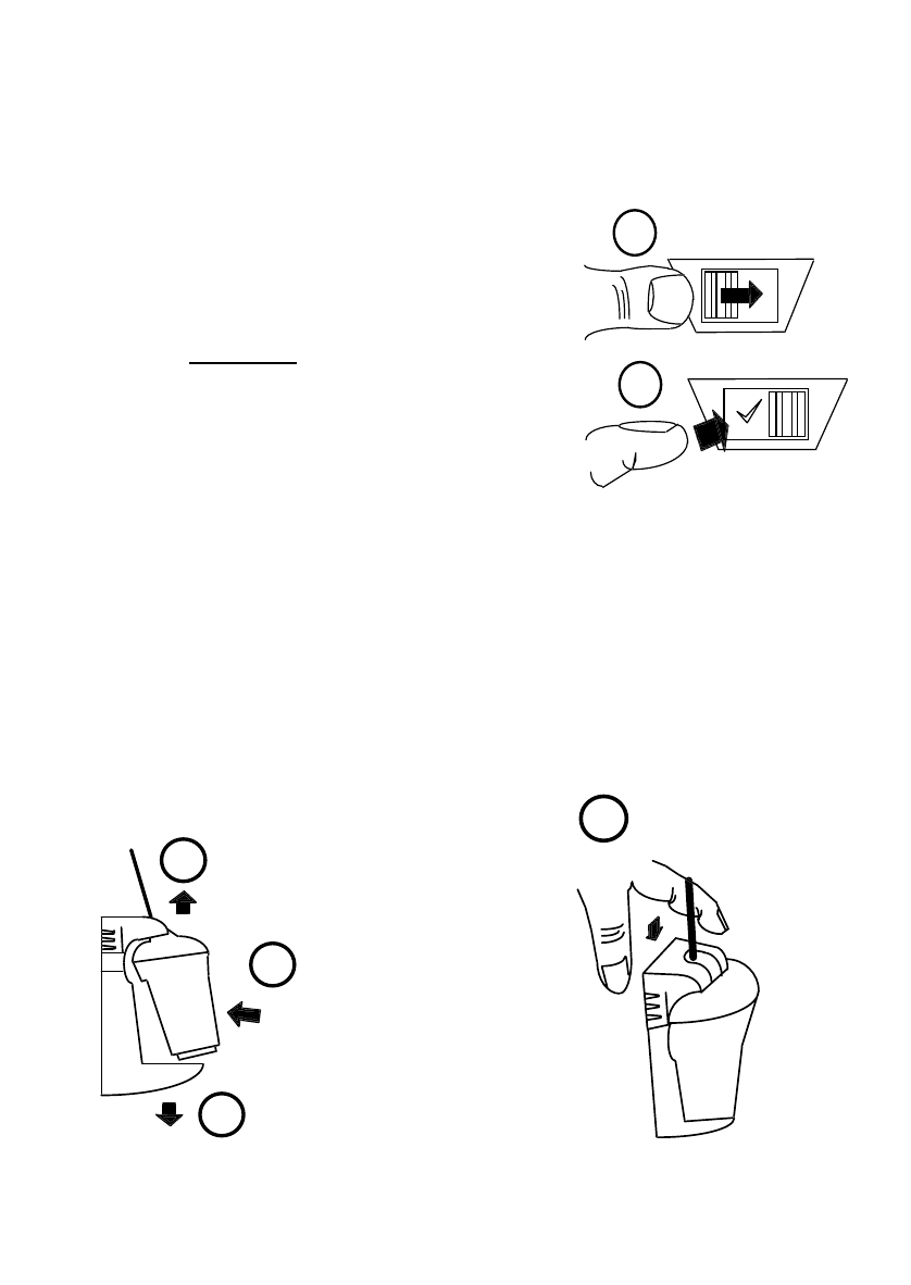
Squeeze top until
it springs up
1
2
Lift up to
free base
3
4
Pull
forward
Pull
down
6 OPERATING PROCEDURE
An EPIRB is a piece of life saving equipment. Its sole purpose is to call for help.
It must only be used in situations of grave and imminent danger.
Misuse can involve a severe penalty.
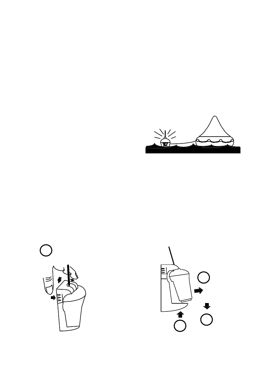
6.1 Sinking
If you have a category 1 “float-free” enclosure (see marking on enclosure label), then if
your vessel sinks, the G4 will automatically release itself from its enclosure before it
reaches a depth of 4 metres. The G4 will float to the surface and start to operate
because its sea switch is activated.
If possible, the G4 should be recovered
and tied (using its lanyard) to one of the
liferafts. An EPIRB is meant to mark
survivors, not the accident scene. For best
operation leave the G4 floating in the sea
near the liferaft.
6.2 Abandon ship
If the vessel is sinking and there is time to fetch the EPIRB then this should always be
done. Release the G4 from its mounting bracket as described in section 6.3 or 6.4 and
carry it to one of the liferafts. Once the liferaft is in the water, uncoil the lanyard and tie
it to the liferaft, then throw the G4 overboard so that it floats next to the liferaft. The G4
will operate because its sea switch will activate.
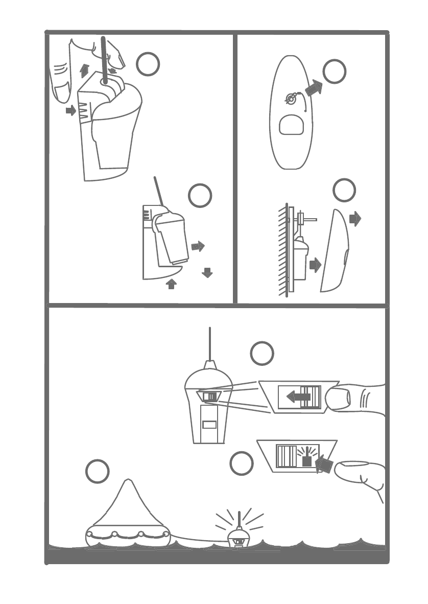
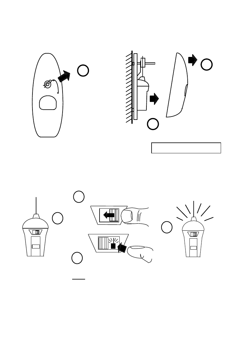
6.3 Releasing G4 from a wall bracket
If you have an G4 fitted into a wall bracket then follow the instructions below to release
it from the bracket:
12
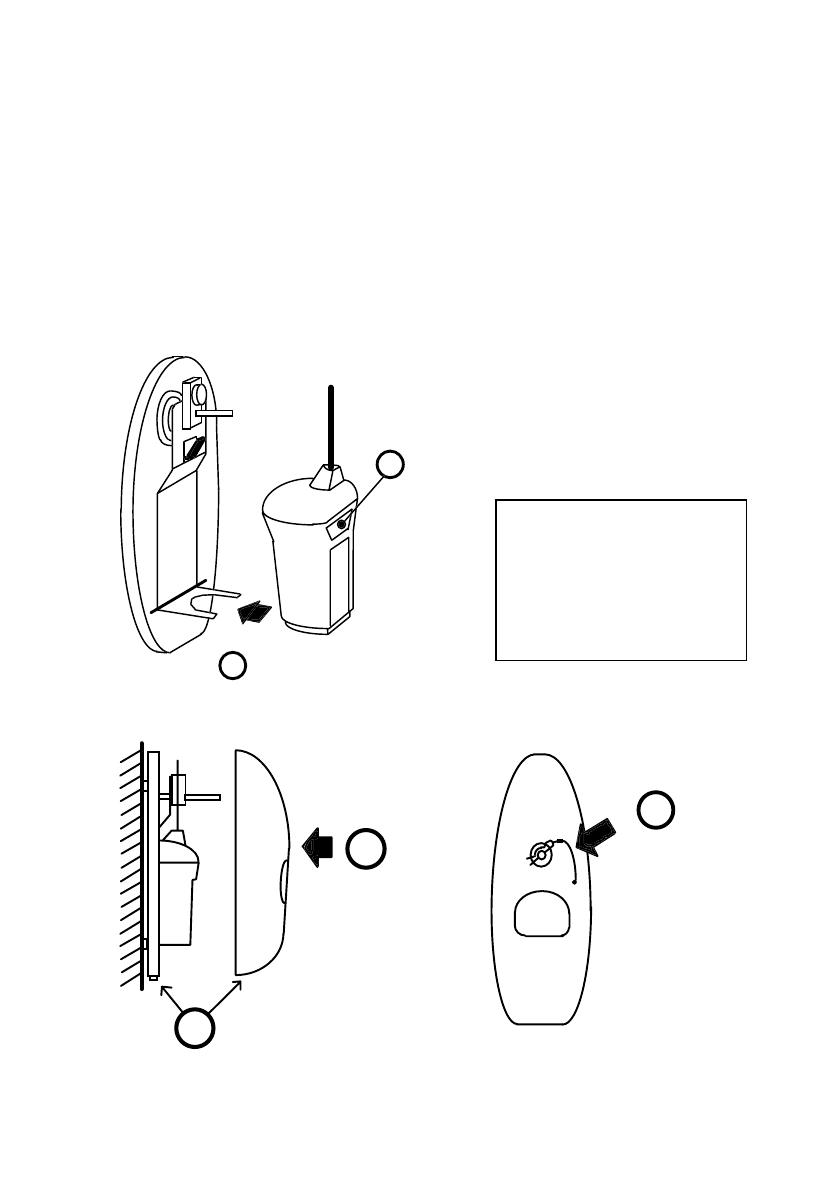
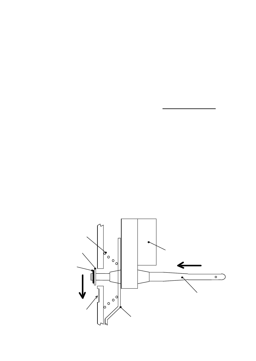
6.4 Releasing G4 from an enclosure
If your G4 is fitted inside a full enclosure then follow the instructions below to release it
manually from its enclosure:
6.5 Manual activation
If the vessel is not sinking, but there is imminent danger, then remove the G4 from its
bracket and activate it manually as shown below. Note that once activated it will flash
immediately, but it will not transmit a distress call for 3 minutes. This gives you a
chance to turn it off if you activated it in error.
Once activated the G4 must have its antenna near upright and it must have a clear
view of the sky for proper operation. Lying it on its side or placing it next to a metal wall
will impair its range and may fail to alert the rescue services. Avoid handling the
antenna, as this will also impair performance.
2
1
Pull R-clip
from pin
Pull
cover
off
3Pull EPIRB
towards you
1
2
3
switches
Locate
on rear
Press ON button
4
EPIRB
will flash
Slide cover to left
Breaking tamper seal
Do not let EPIRB fall out
13
1
2
Slide cover to right
Press READY button
READY
HOLD TO
TEST
1Insert
antenna
2
3
Push
backwards
Push firmly
into cup
Push down
until clip locks
4
6.6 Deactivation
If the G4 was activated by mistake or if the emergency ends then the G4 can be reset
back to its “ready” state as follows:
• Remove EPIRB from any water and dry its
sea switch contacts.
Wait 8 seconds for sea switch to turn off.
If EPIRB is still flashing then it must have been
turned on manually:
• Slide the switch cover fully to the right.
• Press and release READY button.
If EPIRB is still flashing then it has a fault.
Refer to section 7 on False Alarms
.
6.7 Battery condition
If your G4 has been activated for a cumulative
period in excess of 2 hours then its battery will
need replacing. This is necessary to ensure that the next time it gets used it will
operate for the full 48 hours required by government regulations. See section 11.3 for
battery replacement instructions.
6.8 Re-fitting G4
6.8.1 Refitting into wall bracket
The G4 is now in its “ready” state, but its sea switch is still armed and will activate if it
gets wet. To de-activate the G4 fully it must be returned to its mounting bracket, where
a magnet hidden in the bracket will make the G4 safe.
14
6.8.2 Re-fitting into enclosure
• Offer G4 into backplate with switches facing outwards.
• Engage base of G4 into D shaped metal prongs.
• Antenna rests either to left or right of release pin.
• Check G4 is fully engaged in metal prongs and resting on foam pad.
• Refit cover by first locating release pin through hole in cover.
• Locate cover onto backplate, then snap down over locating lug.
• Refit R-clip through hole in end of release pin.
3
Fit cover
over pin
4Snap cover onto
locating lug
5
Fit R-clip
through pin
1
2
Switches
facing
out
Fit D-shaped
foot into prongs
CAUTION
Failure to fit EPIRB
correctly may impair
its ability to float free
in an emergency
15
7 FALSE ALARMS
False alarms are a serious problem for the rescue services. About 90% of EPIRB
initiated distress alerts turn out to be false alarms. If your EPIRB should cause a false
alarm, follow the instructions below.
7.1 Stand down rescue services
It is most important that you contact the nearest search and rescue authorities and tell
them it was a false alarm, so that they can stand down any rescue services. Use any
means at your disposal to make contact. Often this can be by VHF radio to the local
coastguard or mobile phone if you are within coastal range, but MF/HF DSC and
Inmarsat A, B, C,M may also be used. Useful contacts are:
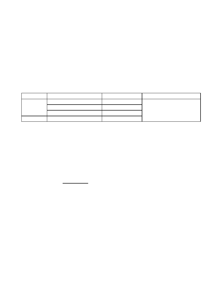
Country Region Telephone What to report
Atlantic / Gulf of Mexico (212) 668 7055
Pacific (510) 437 3700
USA
From any location (800) 323 7233
UK From any location 01326 317 575
EPIRB Unique ID (UIN)
Date, time & duration
Cause of activation
Location when activated
7.2 De-activate the EPIRB
If the G4 was activated by mistake, then de-activation is simple:
• Remove the G4 from any water and dry its sea switch contacts.
• Wait about 8 seconds for the sea switch to de-activate.
• If the G4 is still flashing then it must have been turned on manually…
• Slide the switch cover fully to the right.
• Press
and release the READY button.
• The G4 should now stop flashing.
• Refit the G4 correctly into its mounting bracket or enclosure.
Modern EPIRBs have sea switches and it is not uncommon for the sea switch to
activate in rough seas or heavy rain simply because the EPIRB has been badly fitted in
its mounting bracket. The G4 bracket has a hidden magnet to hold the G4 in an off
state. If the G4 is wrongly fitted the magnet does not do its job and heavy seas may
activate the sea switch. The simple cure is to ensure the G4 is correctly fitted as shown
in sections 6.8 or 6.8.2.

16
7.3 Dealing with a transmitting G4
In the unlikely event that your G4 develops a fault and will not turn off, then prevent its
radio signal from reaching the satellite using one of the following methods:
• Remove the antenna. Wrap the G4 in metal foil and take it below decks.
or
• Remove the antenna and place the G4 in a metal container or locker.
Leave it in this condition for 3 days until its battery is dead. See section 11.4 for
instructions on returning the G4 for servicing. See also section 12.
17
8 WALL BRACKET INSTALLATION
8.1 Siting
The wall bracket should ideally be sited in plain view near an emergency exit. When
choosing a suitable mounting position you should also consider:
• Ease of access in an emergency.
• Mount at least 1 metre (3’) from any compass equipment.
• Allow at least 25mm (1”) above the bracket for it to spring open.
• Allow 18cm (7”) for the antenna. Heavy bending of the antenna is bad.
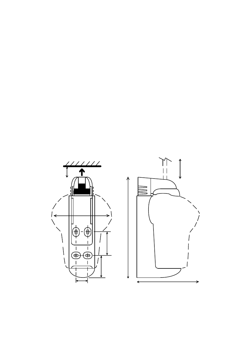
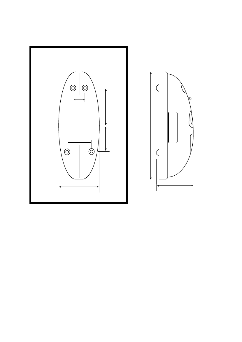
8.2 Mounting procedure
The wall bracket is supplied with a set of stainless steel fixings 25mm (1”) in length.
The bracket mounts against a flat surface using 4 fixing points. Offer the bracket into
the chosen position and mark through the mounting slots. If you are using the nuts and
bolts supplied, drill 6mm (1/4”) holes in the centre of each mark. You will need a 4mm
Allen key to tighten the bolts. If the rear of the mounting surface is inaccessible then
use the self-tapping screws supplied and drill 3mm (1/8”) holes. Always fit washers
under the heads of the screws to avoid damage to the plastic.
175mm
(7")
130mm
25mm
(1")
29mm
(1.14")
59mm
(2.32")
55mm
(2.16")
240mm
(9.5")
115mm
(4.5")
(5.1")
18
8.3 Mounting instruction plate
The G4 is supplied with an instruction plate. This is a rigid plate with basic visual
instructions for how to operate the G4 in an emergency. The plate varies slightly
depending on whether you have a wall bracket or a full enclosure. The wall bracket
version is illustrated below.
The instruction plate should be mounted next to the EPIRB so that it is easily visible in
an emergency. Use the four self-tapping screws supplied to mount the plate. Mounting
dimensions are shown in the diagram above, or you can use the plate itself at a drilling
guide for the screws.
During vessel maintenance, ensure the plate does not get painted over or cleaned
down with strong degreasing solvents.
VRV
2
1
3
4
5
58.4mm (2.3")
70mm (2.75")
130mm
(5.1") 116.3mm
(4.58")
Mount plate
next to EPIRB
19
9 ENCLOSURE INSTALLATION
9.1 Siting
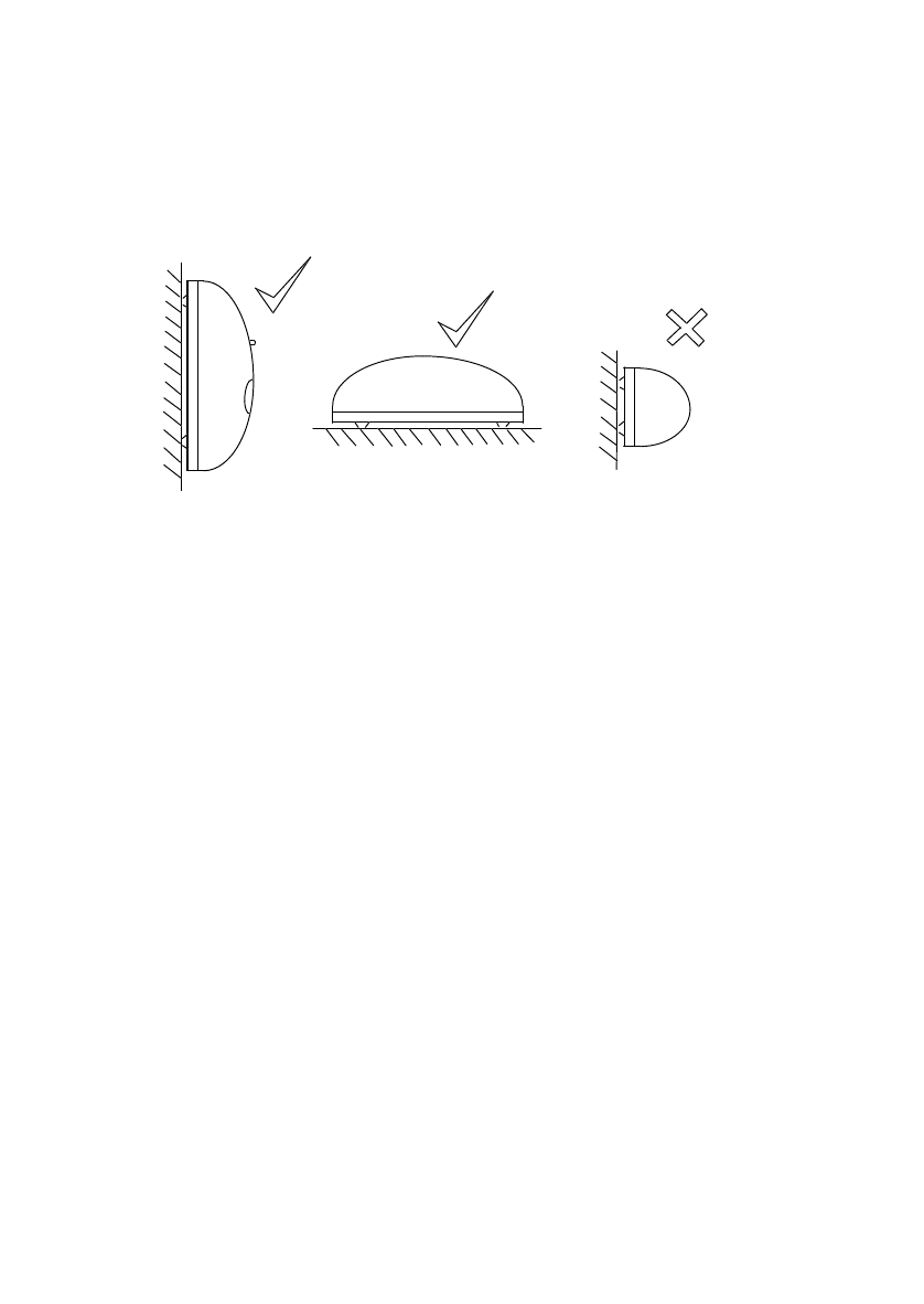
The enclosure should be mounted upright against a vertical bulkhead. Alternately, it
may be mounted horizontally on a flat surface, such as a cabin roof. No other
orientations are recommended
If you have a float-free G4 it is critical that you choose a position where the released
EPIRB will not get trapped by overhangs, rigging, antennas etc, should the vessel
ever sink. An expanse of flat surface is required to allow the enclosure lid to eject. Use
the list below to choose a suitable mounting position:
• Mount on the outside of the vessel’s structure.
• Mount close to the vessel’s navigation position.
• Consider ease of access in an emergency.
AVOID
• Positions with insufficient space for lid ejection and maintenance.
• Positions within 1m (3') of any compass equipment.
• Mounting within 2m (6') of any Radar antenna.
• Direct impact from waves
• Siting where damage is likely.
• Exhaust fumes, chemical and oil sources.
9.2 Mounting procedure
The enclosure mounts against a flat surface using 4 fixing points. See illustration for
mounting dimensions, or use the backplate of the enclosure as a marking guide. To do
this, pull out the R-shaped clip and remove the enclosure lid. Note how the G4 fits then
remove it to somewhere dry (its sea switch is now armed).
Offer the back plate into the chosen position and mark through the mounting holes.
The enclosure is supplied with a set of 25mm (1”) stainless steel fixings. If you are
using the nuts and bolts, drill 6mm (1/4”) holes where you have marked. You will need
20
a 4mm Allen key to tighten the bolts. If the rear of the mounting surface is inaccessible,
use the self-tapping screws supplied. Always fit washers under heads of the screws to
avoid damaging the plastic.
9.3 Mounting instruction plate
The G4 is supplied with a rigid plate giving visual instructions on how to operate the G4
in an emergency. Mount this next to your EPIRB as explained in section 8.3.
9.4 Marking HRU expiry
If you are installing a float-free G4 you must now mark the HRU expiry date. The HRU
has a 2 year in-service life which starts as soon as it gets exposure to a marine
environment. Hence the 2 years starts at installation and it is left to the customer to
mark this date during installation. A date 2 years into the future should be marked on
the HRU body and copied onto the label on the side of the enclosure. The HRU is
marked by cutting out the corresponding dates on its label. The enclosure should be
marked using the alpha-numeric stickers provided, then covering them with the clear
sticky label provided (but see 9.5 first). The preferred date format is month and year,
for example : JUN 2001.
150mm
(5.9")
84mm (3.3")
44mm
(1.73")
104mm
(4.1")
150mm
(5.9")
440mm
(17.3")
140mm
(5.5")
OBSTRUCTION FREE AREA
0.8m x 0.5m (32" x 20")

21
9.5 Marking vessel name
In most countries it is usual to have your EPIRB programmed by your supplier with the
vessel’s existing “callsign” (see registration section below). Your supplier will then mark
all the EPIRB labels accordingly. However, if your EPIRB was purchased in the USA,
Canada or UK then your EPIRB will have all the necessary markings except for vessel
name. In these countries it is left to the customer to mark the vessel name during
installation.
The name must be marked on the rear of the G4 itself and also on the enclosure, if you
have one. Use the alpha-numeric stickers provided to mark the vessel name (or its
abbreviation) on the top line of the G4’s rear label and again on the enclosure label.
Protect the markings with a section of the clear sticky label provided.
You must register your EPIRB with the appropriate authorities.
Failure to register may slow the rescue and lead to loss of life.
In the USA failure to register leads to monetary forefeit.
22
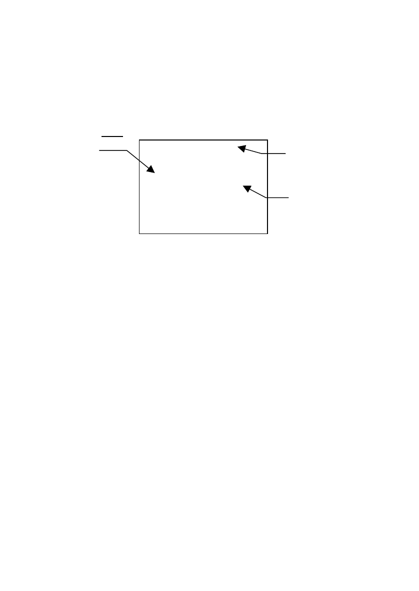
10 REGISTRATION
10.1 Overview
Every EPIRB is pre-programmed with a unique identity before it reaches the customer.
This is done by the manufacturer or in some cases the distributer. The identity includes
a 3 digit country code. This is the country that takes responsibility for storing that
particular EPIRB’s registration details. In most cases this is the country to which the
vessel is flagged. The country programmed into your G4 can be found from its rear
identity label. You must register with this country.
MV BELLANA
EPIRB 1
1D1400063F81FE0
FLAG 232 G BRITAIN
SERIALISED 000012
CATEGORY 1 – AUTO
Class 2 –20/+55 C (-4/+131 F)
When you activate your EPIRB in an emergency, the nearest maritime search and
rescue coordination centre (MRCC) will receive the message and decode the country
code (eg 232). They will then access the registration database for that country and
expect to find details of your vessel, its radio equipment and who to contact. If they fail
to find this information, this may slow down any rescue.
10.2 How to register
Three registration forms are provided, two are for future use and one must be
completed now. The forms are all pre-printed with your EPIRB’s identity, all you have
to do is complete details of your vessel and provide some contact numbers. Wherever
possible the forms are also pre-printed with the correct mailing address and a faxback
number. If your form does not have a mailing address, contact your supplier. When
you have completed the form, you can choose to fax it or mail it.
It is usual to receive confirmation when you register. In the USA you will also receive a
“Decal” sticker which you must fit to the G4 itself. The Decal is proof of registration. Not
having a Decal is an offence. Useful registration contacts are:
USA Sarsat Beacon Registration
E/SP3, RM3320, FB-4
NOAA, 5200 Auth Road
Suitland MD 20746-4304
Tel 888 212 7283 Fax 301 568 8649
UK EPIRB Registery
HM Coastguard (Southern)
Pendennis Point, Castle Drive
Falmouth TR11 4WZ
Tel 01326 211569 Fax 01326 319264
10.3 Warranty form
Please complete the warranty form supplied and fax or mail it to McMurdo. Failure to
do this may delay any future warranty claim.
Vessel
Unique
Identity
Number
Countr
y

23
10.4 Radio licence
An EPIRB is a radio transmitter and must therefore be added to your radio licence. If
you have been allocated a radio callsign, then you already have a radio licence for
your VHF or MF radio set. You should update your licence to include your EPIRB. For
further details see your licence or use these contact numbers…
USA FCC Tel : 888 225 5322 Website : www.fcc.gov\Forms\Form506\506.pdf
UK Wray Castle, PO Box 5, Ambleside, Cumbria LA22 0BF. Tel : 01539 434662
10.5 Sale or transfer
EPIRBs registered in the USA, Canada, UK and Australia do not need to be re-
programmed when transferred to a new vessel. Simply complete another registration
form to inform the authorities of the transfer. Use one of the spare forms provided or
contact McMurdo for a blank form. (See warranty section for address).
For most other countries, the EPIRB must be re-programmed with either the new
vessel’s Maritime Mobile Station Identity (MMSI) or its radio callsign, whichever is
required by the country controlling the new vessel.
Since the EPIRB identity contains a country code, it follows that changing the flag state
of the vessel also means the EPIRB must be re-programmed.
Programming can be carried out at McMurdo or any of our designated agents. For
details of your nearest agent, either contact McMurdo using the details in the warranty
section, or visit the McMurdo web site at www.mcmurdo.co.uk.

24
11 MAINTENANCE
11.1 Monthly self-test & inspection
As an important item of safety equipment, your G4 should be checked regularly. The
G4 has a built-in test capability that can be used as a confidence check. This self-test
confirms that the battery is healthy, that the GPS receiver and both of the distress
transmitters are functional and that the strobe light is operational. The self-test should
be performed monthly. It should be performed during the first 5 minutes of the hour, to
minimise disturbance on the emergency channel.
If your G4 is in an enclosure it can be tested through the test window without having to
remove the G4 from the housing. If you have a bracket mounted G4 it will have to be
removed from the bracket as described in section 6.3. The procedure for self-testing is
as follows:
• On rear of G4 press and hold the READY button.
• The red lamp will come on for 4 seconds to confirm test in progress.
• When the red lamp goes out, the strobe lamp must flash 3 times (at
least).
• If the strobe does not flash, or the red lamp illuminate, repeat the test
then see section 11.4.
During these monthly checks you should take the opportunity to visually inspect the G4
and its mountings for deterioration or damage.
On the G4 itself check the following:
• Inspect the G4 for any obvious damage.
• Check there is no sign of water inside the unit.
• Check that the lanyard is not tied to the vessel structure.
• Check the battery is within its expiry date.
If you have a wall bracket:
• Confirm the bracket top clip springs up when squeezed.
• Check the G4 is correctly fitted and secure in its bracket.
If you have an enclosure:
Check the HRU is within its expiry date (category 1 only).
Confirm the cover can be manually removed with ease.
Ensure the G4 base is correctly fitted into the D-shaped prongs.
If the G4 or its mounting needs cleaning then this should be done using warm soapy
water and a damp (not wet) cloth. Do not use strong detergents or solvents.
Do not paint the G4 or its mounting
Do not clean with detergents or solvents
During vessel cleansing or painting remove the G4 and its mounting.
25
11.2 HRU replacement
If you have an G4 in an enclosure marked Category 1 then it contains a Hydrostatic
Release Unit (HRU). This has a 2 year replacement interval. The expiry date, which is
marked on the HRU and on the enclosure side label should be checked regularly.
When the HRU expires you can obtain a replacement at a local chandler, or direct
from McMurdo at the address shown on the warranty page. McMurdo will supply an
HRU kit (Part No. 82-210B) complete with breakable plastic rod, date labels and
instruction sheet. At a chandler you should ask for a Pains Wessex “Breakthrough
HRU with an EPIRB kit”. The HRU replacement procedure is as follows:
• On the enclosure, remove the R-clip and pull the cover slowly off.
• Remove the G4 and stow it in a dry place. It will activate if wet.
• Hold down the metal lever arm to take up the force of the spring.
• Push the HRU back then upwards out of the slot in the lever arm.
• When the rear clip disengages slowly release the lever arm.
• The HRU with its breakable rod can now be lifted free and replaced.
• Using pliers, remove the rear E-clip and slide off the old HRU.
• Fit the new HRU over the new rod, with its label facing outward.
• Refit the washer and the rear E-clip. Ensure rod moves freely.
• Mark the HRU with an expiry date 2 years into the future.
• Slide the HRU into the slot in the lever arm and push lever arm down.
• Engage rear washer into backplate by pushing back and sliding down.
• Look under the spring and check that the washer is fully engaged.
• Slide G4 into D-shaped foot on lever arm, switches outermost.
• Refit cover by engaging hole over rod and then snapping into place.
• Refit R-clip through top of rod.
• On side of cover, remove old HRU expiry date and mark new date.
1
2
Breakable rod
HRU
Lever arm
Spring
Engage
washer here
Rear E-clip
Fitting HRU
Washer

26
11.3 Battery replacement
The G4 uses a 9V Lithium battery pack, McMurdo type 82-570. Typically this will have
to be replaced every 5 years. The exact battery expiry date is marked on the rear of the
G4 lens dome and if you have a full enclosure it is also marked on the outside of the
enclosure. The battery expiry date should be checked regularly. You will need to
replace the battery when:
• The expiry date has been reached or
• The G4 has been used in an emergency situation or
• A false activation exceeds 2 hours of use.
The battery is a one shot device. It is not rechargeable or user replaceable. Battery
replacement must be carried out by a McMurdo approved service agent. Lithium
batteries have special disposal requirements. Never incinerate a Lithium battery. Never
dispose of one at sea. Your service agent will deal with battery disposal.
11.4 Servicing
All servicing must be carried out by a McMurdo approved service agent. Always call
your nearest agent and talk to their service department before returning suspect
equipment. You can find your nearest service agent from:
• The McMurdo web site: http://www.mcmurdo.co.uk
• Contacting McMurdo direct (see warranty page).
• Contacting a McMurdo distributor
11.5 Transportation
The G4 has no special transportation requirements. Its Lithium battery has been tested
under the “Transportation of Dangerous Goods” regulations and has been declared as
non-hazardous for transportation purposes.
11.6 GMDSS inspections
If your vessel is subject to GMDSS regulations then you can expect to get regular visits
from ship surveyors enforcing national legislation. They will check the expiry dates and
activate the EPIRB to prove that it really works and they will read the identity message
stored inside the EPIRB to check that you have registered it properly. Leisure vessels
are not subject to these inspections. However, in some countries passenger and
fishing vessels are covered by the legislation.
27
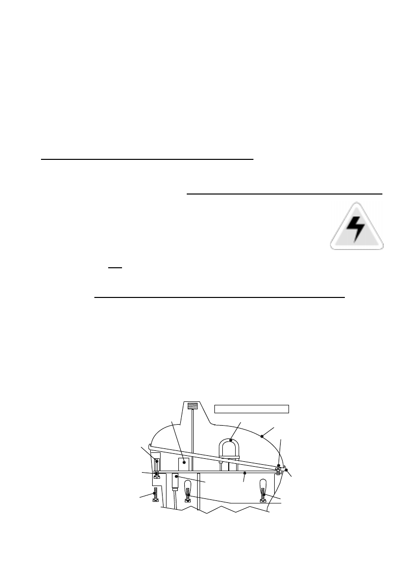
12 FULLY DISABLING A G4
In the unlikely event that your G4 refuses to turn off then it may have a fault.
Procedures for dealing with a faulty G4 are covered in section 7 on false alarms; in
simple terms you should do the following:
• De-activate the EPIRB as described in section 7.2
• Suppress its signal by removing the antenna and wrapping the G4 in
metal foil, as described in section 7.3
• Leave for 3 days until the battery is used up.
We do not recommend any other course of action. However, if it is absolutely
necessary to fully disable an G4 (by unplugging its battery), proceed as follows. This is
a dangerous task and should only be performed by a qualified technician.
WARNING: Risk of electric shock. Proceed at your own risk, no liability accepted
• Take the G4 below decks into the dry.
• Locate a flat bladed screwdriver with a long reach.
• Unscrew and retain the front 4 sealing screws.
• Pull the lanyard out and remove the 2 hidden rear screws.
• Do
not as yet remove the sea contact screws.
• Lift the lens dome off. Remove and retain the grey gasket.
• Avoid touching the circuit board and the glass strobe tube.
• Hold the hexagon shaped pillars and remove the sea screws.
• Use a cross-headed screwdriver to remove the front screw.
• Grip the white plastic coil former and lift the circuit board up 3cm (1”).
• Using fingers, unplug the white 4-way battery connector.
• The flashing will now cease.
• Collect all the parts and return them to your nearest service agent.
Strobe
Front screw
Gasket
Hidden
screws
Sea
screws
Battery
connector
DANGER - HIGH VOLTAGE
sealing
screws
Front
pillar
Hex
Pull up on
coil former
Lens dome
Circuit
board
270V DC

28
13 TECHNICAL SPECIFICATION
406MHz Transmitter Operating frequency 406.028 MHz + 1kHz
Power output 5W typical
Modulation Phase (16K0GID)
121.5MHz Homer Operating frequency 121.5 MHz +/- 3.5kHz
Power output 50mW radiated typical
Modulation Swept tone AM (3K20A3X)
GPS Receiver Centre frequency 1.57542GHz
Sensitivity -175dBW minimum
Satellites tracked 12 max
Strobe light Type Xenon discharge tube
Light output 0.75 Candela minimum
Flash rate 23 flashes per minute
Battery Type Lithium manganese dioxide
Operating life 48 hours minimum
Shelf life 5 years typical in service
Environment Operating temperature -20°C to +55°C (class 2)
Storage temperature -30°C to +70°C
Automatic release depth 4 metres max. (13 feet)
Physical Weight 770 grammes (1.7 lb)
Height of body 21 cm (8.2 inches)
Length of antenna 18 cm (7 inches)
Approvals Satellite system Cospas-Sarsat T.001/T.007
Europe ETS-300-066
Marine Equipment Directive
USA USCG / FCC approved
FCC ID : KLS-82-501
Worldwide IEC1097-2
Meets IMO regulations A662(16) A694(17)
A810(19) A814(19)
This device complies with the GMDSS provisions of part 80 of the FCC rules.
The GPS module complies with the relevant sections of IEC1108-1:1996.

29
McMurdo Limited Product Warranty
Subject to the provisions set out below McMurdo Limited warrants that this product will be free of
defects in materials and workmanship for a period of 12 months from the date of purchase.
McMurdo Limited will not be liable to the buyer under the above warranty:-
• for any defect arising from fair wear and tear, wilful damage, negligence, abnormal working
conditions, failure to follow McMurdo Limited's instructions (whether oral or in writing)
including a failure to install properly and/or to use batteries recommended and/or supplied by
McMurdo Limited, misuse or alterations or repair of the product by persons other than
McMurdo Limited or an Approved Service Agent;
• for parts, materials or equipment not manufactured by McMurdo Limited in respect of which
the buyer shall only be entitled to the benefit of any warranty or guarantee given by the
manufacturer to McMurdo Limited;
• for the battery storage life which is specifically excluded from this warranty;
• if the total price for the product has not been paid.
McMurdo Limited does not make any other promises or warranties (express, implied or statutory)
about the product except where the product is sold to a consumer in which case the statutory
rights of a consumer are not to be affected.
In order to be valid, claims must be made under the above warranty in writing as soon as
practicable after discovery of the defect or failure and within the warranty period referred to above.
Proof of purchase will be required. The claim should be sent together with the product in question
to the address set out below or to an Approved Service Agent.
Following a valid warranty claim McMurdo Limited shall be entitled to repair or replace the product
(or part) in question free of charge, or at McMurdo Limited's sole discretion to refund to the buyer
the price of the product (or a proportional part of the price). McMurdo Limited shall not be liable to
a buyer who is not a consumer for any other loss or damage (whether indirect, special or
consequential loss of profit or otherwise) costs, expenses or other claims for compensation which
arise out of or in connection with this product. In the case of a consumer McMurdo Limited shall
only be liable where other loss or damage is foreseeable.
Nothing shall limit McMurdo Limited's liability for death or personal injury caused by its
negligence.
This warranty is to be interpreted under English law.
All enquiries relating to this warranty or Approved Service Agents should be sent to:
McMurdo Limited
Rodney Road
Portsmouth
Hampshire
PO4 8SG
United Kingdom
Telephone: Int + 44 (0) 23 9277 5044 Fax: Int + 44 (0) 23 9281 9087
Web: www.mcmurdo.co.uk Email: sales@mcmurdo.co.uk

30
Record Serial No. (visible through dome) : _______________________
McMurdo Ltd
Rodney Road
Fratton
Portsmouth
Hampshire
United Kingdom
PO4 8SG
A member of Chemring Group PLC
82-569-001M Issue 1