Orolia NAV-7 NAVTEX Receiver User Manual 35 821N Iss1 NAV 7
Orolia Ltd NAVTEX Receiver 35 821N Iss1 NAV 7
Orolia >
Contents
- 1. User Manual Part 1
- 2. User Manual Part 2
User Manual Part 2
23
Warning: Do not mount the NAV-7 in a position where sea spray can reach it, or
where it may be exposed to direct sunlight

24
DISPLAY ELECTRICAL INSTALLATION
This manual is concerned only with the installation of the NAV-7 and does not cover
the installation of any peripheral equipment connected to the NAV-7 such as
printers, navigational systems or source of NMEA data. For proper installation and
connection of peripheral equipment to the NAV-7 refer to the installation manuals
for these products.
The table below shows the connections that must be made to the NAV-7 for it to
function correctly.
Connection Must connect Optional
Ship’s earth connection ü
12V or 24 V DC power supply ü
NAVTEX antenna ü
Alarm Relay ü
NMEA or IBS time reference See Note 1 See Note 1
Integrated Bridge/Navigation System ü
External printer ü
Note 1: Connecting a time reference (eg a GPS receiver) is highly recommended.
Ship’s earth connection
The earth terminal on the rear of the NAV-7 display must be connected to ship’s
ground by the earth cable supplied. The earth connection should be kept as short
as possible.
Safety Warning
To ensure the best possible protection of the NAV-7 from static electricity
or nearby lighting strikes, the pre-fitted green grounding wire (connected
to the safety earth spade) must be connected to a nearby (hull) electrical
grounding point.

25
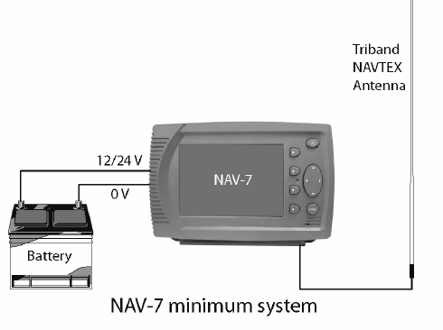
12V or 24 V DC power connection
A connection must be made to a 12 or 24 V DC supply via a circuit breaker capable
of supplying at least 2 amps. Connection should be to the ship’s radio battery and
be in accordance with GMDSS requirements.
• Connections should be made using the 2 m power cable provided
• Use cable ties to restrain the wiring, and so prevent it becoming weakened
by vibration. The connecting cables should be restrained by securing them
to the rear of the NAV-7 bracket, or to adjacent metalwork
• The screen of the cable should be connected to ship’s earth if possible.
The screen of the cable should not be connected to ship’s battery –ve
Safety Warning
The NAV-7 has been designed and manufactured to be completely safe
when used in accordance with the instructions given in this manual. To
ensure that the complete installation is safe, it is essential that a fuse or
circuit breaker is installed in the power supply cable as described in the
Installation section of this manual.
Isolation between the power supply connections and any other connection to the
NAV-7 is 1 kV minimum.
The DC power source should comply with IMO guidelines for the class of vessel
concerned. National authorities and classification societies may have their own
power supply requirements; these should also be considered.
Signal cable connections
As shown in the table above, the NAV-7 may be connected to different types of
peripheral units including IBS & INS serial ports and printers.
The signal connections are all connected via a serial RS422 type interface; data
rates are selectable at 4800, 38400 or 115200 baud.
In some cases, particularly in retrofit installations, it may not be possible to connect
the NAV-7 directly to the required source/destination for serial data, because some
equipment does not provide the IEC 61162-2 (NMEA) sentences required by the
NAV-7 unit. In such cases a protocol converter is required between the sensor and
the NAV-7. Converters are available from different manufacturers, either as direct
protocol converters or frequently as repeater instruments for the sensor.
26
1
5
6
11
15
10
Signal line termination
RS422 signal lines may need termination resistors at the far end of the serial cable
connected to the NAV-7, depending on the length of connecting cable and the rate
of data transmission. Both the IBS and the NMEA ports in the NAV-7 have inbuilt
100O termination resistors for both Tx and Rx.
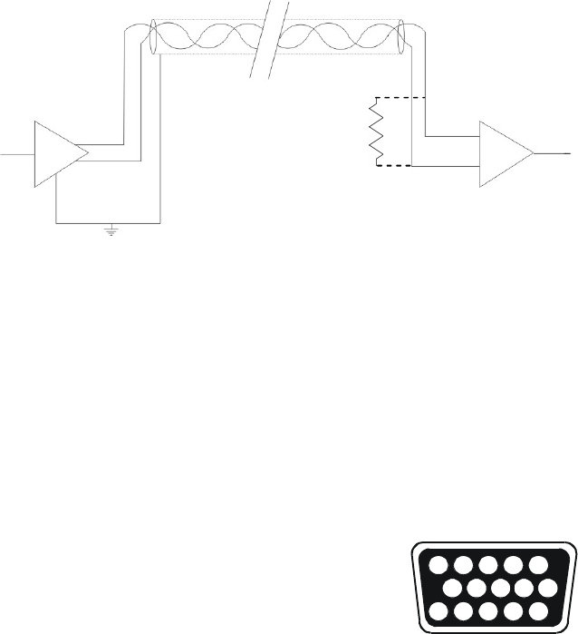
Whether termination is required depends on many factors, particularly the length of
the signal cable and the environment in which the equipment is operating. The
principle is shown in the sketch:
There is only one talker per twisted pair; there can be several listeners. The
intention is that terminations must be provided by the devices at the ends of the
line, regardless of whether they are listeners or the talker, and that no other device
should provide a termination.
Since the NAV-7 contains internal termination, it MUST be at the end of the line and
NOT in the middle.
It is good practice to use screened cables in all ship cable installations. Take care to
connect the cable screen to ship’s ground at one end only of the cable, as
connecting at both ends may cause ground loops and interference to the signals.
The cable screen should not be connected to any part of the NAV-7.
Connecting to the IBS serial interface
The display connection cable is supplied ready for
use, and needs only to be plugged into the
appropriate connector on the NAV-7.
Display cable: Six twisted pairs, screened, PVC
sheathed. For lengths to 200 meters, use 0.22 mm2
(7/32); Belden 8106 or equivalent.
The connections to the15-pin socket on the NAV-7 are given below. Note that the
cable screen should not be connected to any part of the NAV-7.
Talker
(NAV-7)
Listener
(may need termination)
Ground cable
screen at
NAV-7 ONLY
Terminating
resistor
27
1
5
6
9
Power, Alarm & IBS port (2m cable supplied)
Pin
Number
Connection NAV-7 Cable Colour Notes
1 IBS_TXA O/P WHITE/BLUE O/P to IBS port
2
3 +V
(12/24 V DC nominal)
I/P RED/BLUE Ship’s supply +ve
4 -V (0V) I/P BLUE/RED Ship’s supply -ve
5
6 IBS_TXB O/P BLUE/WHITE O/P to IBS port
7
8 AUX_NC O/P ORANGE/WHITE Alarm Relay NC
9 AUX_NO O/P WHITE/BROWN Alarm Relay NO
10 AUX_COM O/P WHITE/GREY Alarm Relay COM
11
12 IBS_RXB I/P GREEN/WHITE I/P from IBS port
13 IBS_RXA I/P WHITE/GREEN I/P from IBS port
14
15
Connecting to the NMEA 0183 interface
If a connection to NMEA 0183 compatible equipment is
required then a suitable cable has to be purchased or
manufactured.
Recommended NMEA 0183 cable: Two twisted pairs,
screened, PVC sheathed. For lengths to 200 meters, use
0.22 mm2 (7/32); Belden 8102 or equivalent.
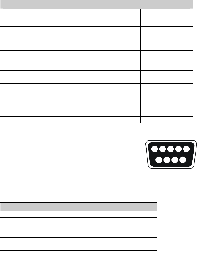
The connections to the D-Sub 9-pin socket on the NAV-7 are given below. Note that
the cable screen should not be connected to any part of the NAV-7.
NMEA 0183 & printer port
Pin Number Connection Notes
1
2 SER_TXB O/P to NMEA 0183 (printer)
3
4 SER_RXB I/P from NMEA 0183
5
6
7 SER_TXA O/P to NMEA 0183 (printer)
8 SER_RXA I/P from NMEA 0183
9
28
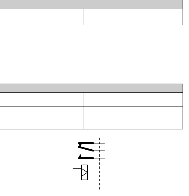
Alarm relay
The NAV-7 provides a relay connection which can be selected as normally closed
or normally open contacts.
The alarm relay function is configurable from within the setup pages and can be set
(for example) to switch (change state) on receipt of a Search and Rescue
message or for a system fault.
The red LED on the front panel of the NAV-7 mirrors the function of the alarm relay.
Red LED function
LED OFF Alarm relay NC contact closed
LED ON Alarm relay NO contact closed
Recommended cable for connection of alarm relay:
One twisted pair, shielded, PVC sheathed. The required cable dimension is
dependent on the current necessary to activate the alarm indicator.
Built in alarm relay ratings:
Alarm relay absolute maximum ratings
Maximum switching current in
contacts (inductive load)
1.0 Amp
Maximum switching current in
contacts (resistive load)
3.0 Amp
Maximum switching voltage 120 V AC or 24 V DC
NAV-7 External connections
N/C
Com
N/O
29
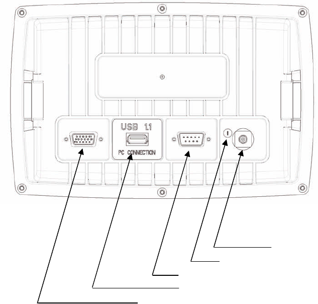
Connector pin-outs
NAV-7 rear panel connections:
• The auxiliary alarm contact is capable of switching up to 24 V DC at up to 1 A
(inductive load). The contacts are not connected to any internal voltages.
• The power supply input is isolated from the case and antenna. It must remain
within the range 10.8 – 31.2 V DC (12/24 V DC nominal) at all times.
TNC RF connector
1/8” Spade terminal – ground pin
9-way D-type – NMEA 0183 & printer port
USB connector – for in-field programming
15-way D-type – power and IBS port and alarm relay
30
ANTENNA INSTALLATION
Selecting a suitable antenna
The NAV-7 receives transmissions on three frequencies. 518 kHz transmissions are
in International English; 490 kHz and 4209.5 kHz transmissions may be in a local
language.
To receive on all frequencies the NAV-7 must be used with a wide frequency
(400kHz to 5MHz) antenna that covers 518 kHz, 490 kHz and 4209.5 kHz.
If you have purchased the NAV-7 receiver without an antenna then a suitable active
NAVTEX antenna should be used. McMurdo supplies a suitable wide frequency
antenna with the NAV-7 System; this antenna can be purchased separately as Part
No. 905-05.
If the Installer is supplying an alternative antenna, note that the NAV-7 must
be used with a low impedance 50 ohm antenna or an antenna with a 50 ohm
matching network. A mis-matched or high impedance whip or wire antenna
should not be used as the operational range of NAVTEX reception may be greatly
reduced; it is also important that the antenna is capable of reception over the
frequency range specified above.
If a Wire or long whip antenna is used with the NAV-7 it must be fitted with a 50
ohm matching transformer. Take care that the antenna power is disabled – refer to
Setup – Receiver mode for details. A qualified installer should be consulted.
31
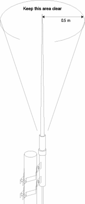
Important
NAVTEX antennas must be mounted clear of obstructions and at least 0.5
metres away from other antennas.
Where practical avoid locating the NAVTEX antenna close to MF / HF
transmitting antennas or VHF / AIS antennas.
Ensure that antennas cannot be snagged by mooring warps or running
rigging or engulfed by green water.
Antennas should always be mounted vertically.
32
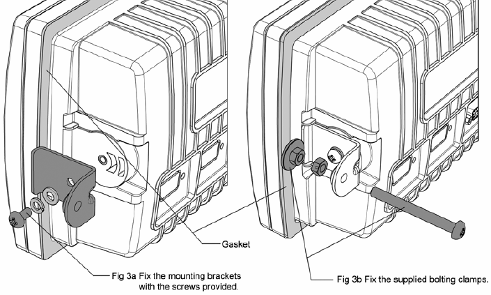
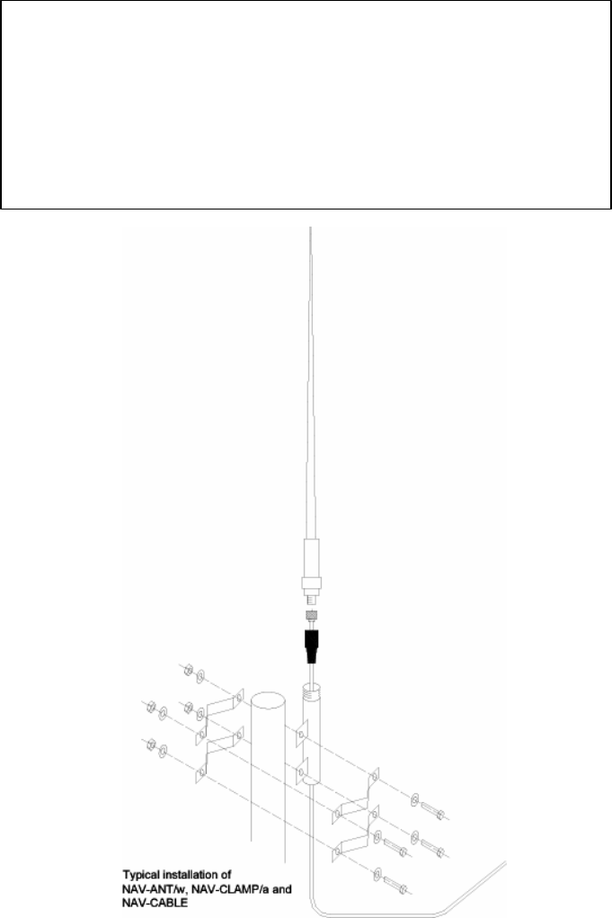
Installation of the tri-channel NAVTEX antenna
The NAVTEX antenna should be mounted vertically, in an elevated position. Metal,
rigging or other antennas must not be located in the 'NO GO cone' surrounding the
upper part.
Use the mounting bracket supplied; an alternative mounting kit may be purchased if
the mounting arrangement is unsuitable for your installation.
Attach the clamping brackets to the antenna mounting adapter and use the
clamping arrangement to fix to a suitable vertical tube.
Thread the PL259 connector end of the coax cable through the antenna mounting
adapter and secure the connector to the antenna 1" threaded adapter.
33
Slide the rubber boot over the PL259 connector; if desired, it may be filled with
silicone grease for a better weatherproof seal.
Screw the antenna down into the antenna mounting adapter.
Ensure that the mounting adapter is connected to ground. If necessary, connect a
grounding wire, 2.5 mm2 minimum, to a suitable ground point.
Installation of the antenna cable
Start routing the antenna cable at the antenna end.
Where the cable passes through bulkheads or decks, waterproof deck glands
should be installed. Securely fasten the cable against vibration using plastic cable
tie wraps.
Complete routing of the antenna cable at the NAV-7 TNC connector.
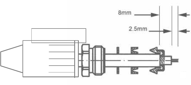
Fitting the TNC connector
A TNC connector is supplied as part of the NAV-7 Receiver Kit.
Fit the TNC connector as shown below:
• Place the rubber boot, gland nut, washer and rubber seal onto cable.
Remove the outer insulation for a distance of 8mm.
• Slide the cable braid sleeve over the screen braid, fold the braid back and
trim off extra braid.
• Strip 2.5mm of the inner insulation to expose the centre conductor.
• Solder the pin onto the centre conductor.
• Assemble the connector and tighten the gland nut. Push the rubber boot
securely over the gland nut.
Rubber boot
Rubber boot

34
Extending the antenna coax cable
If required, the coaxial cable may be extended with 50 ohm coaxial cable and
connectors. The maximum cable length should not exceed 100 m. Ensure that any
cable joints are well secured and waterproofed using self-amalgamating (rubber)
tape.
Cable should be RG-58 / RG-67 / RG-213 / RG-214 grade or better; connectors
should be suitable RF types (TNC, BNC, etc).
Testing the tri-channel active antenna installation
By default the NAV-7 provides a regulated 12 V DC (nom) 100 mA output to provide
power for an active antenna such as the one supplied as part of a NAV-7 System.
If you are using an alternative active antenna please check that it is compatible with
this power output. If it is not, then an external power supply interface will be
required. Your antenna supplier should be able to provide this.
WARNING
Take care not to apply power to the antenna TNC connector
from an external supply
Switch on the NAV-7 by applying power (12 V DC or 24 V DC) via a circuit breaker
or fuse.
There will be a few seconds delay whilst the software loads the contents of the
NAVTEX message store during which time the front panel red LED will blink.
The LCD display backlight will come on and the NAV-7 start-up screen will be
shown.
If the antenna fault icon appears along the top of the display, switch off immediately
and check for a short circuit at the antenna, the TNC connector or any other RF
connections in-between. If the fault persists then please follow the trouble shooting
guide in this manual.
35
Testing the Banten active antenna
If it is suspected that reception is being compromised by the antenna performance,
the antenna should be checked for electrical damage.
Disconnect the antenna from the NAV-7 by unscrewing the TNC connector at the
back of the NAV-7.
Using a DVM set on resistance, measure across the TNC RF connector from the
centre pin to the outer ferrule, looking back up towards the antenna. DO NOT
ATTEMPT TO MEASURE THE RESISTANCE OF THE TNC SOCKET ON THE
NAV-7.
A good antenna will show a reading in the range 1500 – 2000 ohms.
A failed antenna will show a reading < 1000 ohms.
If a reading of greater than 5000 ohms is measured, then there is a continuity
problem with the connector or cable; these should be checked for damage or
misconnection.
Note that these resistance values only apply to a Banten active antenna as supplied
by McMurdo. Other active antennas will have different resistance readings; consult
the supplier in order to check such antennas.
Testing a passive antenna installation
The NAV-7 regulated 12 V DC 100 mA output can be disabled for passive antenna
installations or for installations using a matching transformer.
NOTE: This should be done the first time that power is applied to the NAV-7
BEFORE the antenna is connected.
Switch on the NAV-7 by applying power (12 V DC or 24 V DC) via a circuit breaker
or fuse.
There will be a few seconds delay whilst the software loads the contents of the
NAVTEX message store during which time the front panel red LED will blink.
The LCD display backlight will come on and the NAV-7 start-up screen will be
shown.
If the antenna fault icon appears along the top of the display, switch off immediately
and check for a short circuit at the antenna, the TNC connector or any other RF
connections in-between. If the fault persists then please follow the trouble shooting
guide in this manual.
36
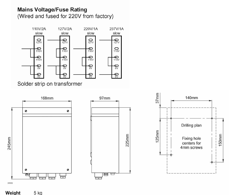
OPTIONAL POWER SUPPLY UNIT 89-029
Consult the installation instructions packed with the power supply.
An additional ground wire may be connected between the green safety earth wire
on the NAV-7 and the ground terminal on the NAVTEX Power Supply Unit.
Dimensions and drilling plan
Technical specification Power supply wiring
110 V AC 1.6 A 110 V AC 2 x 1.5 mm2
230 V AC 0.8 A 230 V AC 2 x 0.7 mm2
24 V DC 7.0 A 24 V DC 2 x 6.0 mm2

37
Maintenance Guide
General Points to Check
• Periodically make sure that the antenna connector is well sealed and that
there isn’t sign of corrosion around the PL259 connector
• Make sure connections to the back of the NAV-7 display are secure
Cleaning Instructions
• Periodically clean the LCD front window with a soft lint-free cloth (such as
those supplied by opticians to clean spectacles)
• Do not used cleaning solvents on any part of the NAV-7
Disposal at end of life
At the end of its life dispose of this product in accordance with local regulations.
OPTIONS
NAV-7 ancillary parts:
Model Description Code
Active NAVTEX
antenna
518 – 490 kHz + 4209.5 kHz, PL Socket, white glass
fibre construction with 1inch nut fitting
905-05
NAV-CLAMP Pole mount stand-off bracket for NAVTEX Antenna,
1inch bolt mount fitting.
903-01
NAV-CLAMP /b Pole or Wall mount stand-off bracket for NAVTEX
Antenna, 1inch bolt mount fitting
903-02
NAV-CLAMP /c Deck mount for NAVTEX antenna, 1inch bolt mount
fitting
903-04
NAV-CABLE 20 20 m antenna cable kit 35-820
External Power Supply
Unit
AC/DC + auto changeover to reserve power
110 / 220 V AC input
89-029
38
TROUBLESHOOTING GUIDE
General Points to Check
• Make sure that the antenna is mounted vertically, and is sited clear of
obstructions
• Make sure the vessel is operating within the coverage area of a NAVTEX
transmitter
• When the NAVTEX station(s) selected are transmitting, icons for 490, 518
and 4209.5 kHz show whenever a NAVTEX signal is received
• Ensure that the required NAVTEX station and message categories have not
been deselected in the NAV-7 setup menu
Antenna fault icon appears at the top of the display: active antenna
1 Turn off the NAV-7
2 Disconnect the active antenna and check that there is not a
short across the antenna’s TNC connector
3 Turn on the NAV-7, apply a 120 ohm 5 W resistor across the
TNC connector. If there is 12 V DC across the TNC then
either the antenna or coax cable is faulty
4 If there is not 12 V DC across the TNC connector then check
that Antenna power : Enabled is selected in the setup
screens
5 If these instructions do not work then please contact your
service agent
Antenna fault icon appears at the top of the display: passive antenna
1 Turn off the NAV-7
2 Disconnect the passive antenna and check that there is not a
short across the antenna TNC connector
3 Check that Antenna power : Disabled is selected in
the setup screens
4 If these instructions do not work then please contact your
service agent
39
The NAV-7 is not receiving
1 Are you within range of a NAVTEX transmitting station?
2 Has there been a scheduled transmission since the NAV-7
was first switched on?
3 Check that the antenna is clear of obstructions and has not
suffered external damage
4 Check that the antenna cable is not damaged
5 Check that the antenna fault icon is not being displayed on
the status bar at the top of the display
6 From within the setup screens, check that the NAVTEX
transmitting stations and message categories are correctly
selected and that they have not all been disabled
7 From the Setup mode: receiver options screen
check that there isn’t a strong local interfering signal
8 Please contact your service agent
Software upgrade
From time to time software upgrades may be available. Check our website for
information on new releases.
External receiver
The NAV-7 has the capability to receive from an external receiver (not supplied) on
an additional NAVTEX frequency should such an additional frequency be mandated
by the IMO in the future.
NAVTEX messages from the external receiver appear on the View EXTERNAL
RECEIVER page.
The external NAVTEX data must be presented as a stream of NMEA NRX
sentences as defined in Annex C of the IEC61097-6 Ed.2 (2005) specification.
The external receiver may be another NAV-7; in such a case, a single antenna may
serve several displays. For more information, contact McMurdo Customer Service.

40
SPECIFICATIONS
Complies with
technical standards:
IMO Resolutions MSC.148(77) A.2.1,
A694 (17)
SOLAS Regulation IV/7.1.4
ITU-R M.540-2, ITU-R M.625-3,
IEC 60945-4
IEC 61162-1,-2, IEC 61097-6
Receivers
RxA Receiver
Frequency
518 kHz
RxB Receiver
Frequency
490 kHz
RxC Receiver
Frequency
4209.5 kHz
Sensitivity <2 microvolts
Frequency stability +/- 10 Hz
Antenna Input 50 ohms
NAVTEX Reception conforms to ITU-R 540-2,
IEC 61097-6
NAVTEX message
memory
Stores at least 1000 x 500
character messages
Environmental Meets the relevant parts of
IEC60197-2 and IEC 60945-4 for
‘protected’ equipment
Compass safe
distance
0.87 metres
Display ½ VGA (480 x 320 pixels)
Colour STN
CCFL backlight
Controls LCD backlight dim/contrast
‘Enter’ key
Four soft keys
Tracker pad
Menu languages
supported
English
Alphabets supported English, Cyrillic
Rear Connections Power, Alarm & IBS port
NMEA 0183 port
USB port (unused)
Antenna connector
Earth stud
IBS Port Serial
Interface
15 way D-type
Conforms to IEC 61162-2
8 data, 1 stop, no parity
Baud rates 4800, 38400, 115200
Supports (in priority order) RMC,
GLL, ZDA for date and time
Supports NRX, NRQ, NMK, ACK,
ALR for NAVTEX functions
MEA 0183 / Printer
Serial Interface
9 way D-type
Conforms to IEC 61162-1
8 data, 1 stop, no parity
Baud rates 4800, 38400, 115200
Supports (in priority order) RMC,
GLL, ZDA for date and time
Supports NRX, NRQ, NMK, ACK,
ALR for NAVTEX functions
USB Serial Interface Type A connector
USB 1.1 (device) interface (unused)
Antenna connector TNC connector
50 ohms
12 V DC @ 100 mA for active
antennas, auto-sensing
Alarms
(internal buzzer)
Vital message receipt
Antenna fault alarm
Alarm Relay Rating 1A @ 120 V AC / 24 V DC (max)
Operating
Temperature Range
-15° to +55° C
Storage Temperature
Range
-20° to +55° C
Humidity 0 to 95%, non-condensing
Mounting Below decks, desk-top, bulkhead or
panel mount
Weight including
bracket
1100 g
Dimensions 219 mm W x 151 mm H x 76 mm D
Mounting Shelf/bulkhead or panel mount
(both kits provided)
Power
Voltage range 12/24 V DC nominal
(10.8 V to 31.2 V)
Consumption,
backlight dimmed
5.7 W @ 24 V DC
Consumption,
backlight full on
8.6 W @ 24 V DC
Fused internally 1.8 A resettable type
McMurdo reserves the right to change specifications without notice.
41
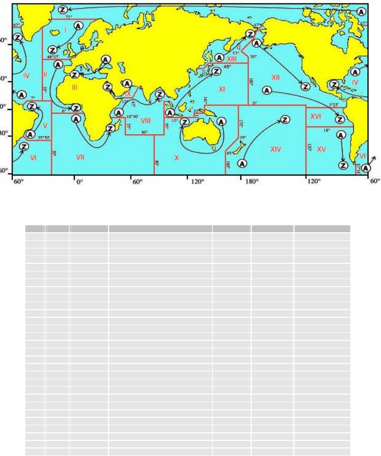
Appendix I: NAVTEX station database
518kHz NAVTEX stations
Id Area Country Name Latitude
Longitude
Range (NM)
A 15 Chile Antofagusta 23°40’ S
70°25’ W
300
A 09 Iran Bushehr 28°58’ N
50°50’ E
300
A 02 France Corsen 48°28’ N
5°3’ W
300
A 11 Indonesia Jayapura 2°31’ S
140°43’ E
300
A 04 USA Miami 25°30’ N
80°23’ W
240
A 03 Russia Novorossiysk 44°43’ N
37°47’ E
300
A 01 Norway Svalbard 78°4’ N
13°38’ E
450
A 13 Russia Vladivostok 43°7’ N
131°53’ E
280
B 11 Indonesia Amboina 3°42’ S
128°12’ E
300
B 09 Bahrain Bahrain 26°9’ N
50°28’ E
300
B 04 Bermuda Bermuda Harbour 32°23’ N
64°41’ W
280
B 01 Norway Bodo 67°16’ N
14°23’ E
450
B 13 Russia Kholmsk 47°2’ N
142°3’ E
300
B 03 Ukraine Mariupol 47°6’ N
37°33’ E
280
B 15 Chile Valparaiso 32°48’ S
71°29’ W
300
B 07 Namibia Walvis Bay 23°3’ S
14°37’ E
380
C 07 South Africa Cape Town 33°41’ S
18°43’ E
500
C 08 Mauritius Mauritius 20°10’ S
57°28’ E
400
C 01 Russia Murmansk 68°58’ N
33°5’ E
140
C 03 Ukraine Odessa 46°29’ N
30°44’ E
280
C 13 Russia Petropavlosk 53°0’ N
158°40’ E
280
C 12 USA San Francisco 37°55’ N
122°42’ W
350
C 04 Canada Sept -Iles 50°11’ N
66°7’ W
300
C 11 Singapore Singapore 1°20’ N
103°42’ E
400
C 15 Chile Talcahuano 36°42’ S
73°6’ W
300
D 02 Spain Coruna 43°22’ N
8°27’ W
400
D 01 Sweden Grimeton 57°6’ N
12°23’ E
299
D 03 Turkey Istanbul 41°4’ N
28°57’ E
300
D 13 Russia Magadan 59°40’ N
151°1’ E
000

42
Id Area Country Name Latitude
Longitude
Range (NM)
D 12 Canada Prince Rupert 54°18’ N
130°25’ W
300
D 15 Chile Puerto Montt 41°29’ S
72°57’ W
300
D 04 Canada Sept -Iles 50°11’ N
66°7’ W
300
D 11 Indonesia Ujungpandang 5°6’ S
119°26’ E
300
E 13 Russia Beringovskiy 64°10’ N
179°02’ W
000
E 11 Indonesia Jakarta 6°7’ S
106°52’ E
300
E 15 Chile Magallanes 52°56’ S
70°54’ W
300
E 01 UK Niton 50°35’ N
1°18’ W
270
E 03 Turkey Samsun 41°17’ N
36°20’ E
300
E 12 USA Savannah 32°8’ N
81°42’ W
200
F 03 Turkey Antalya 36°53’ N
30°42’ E
300
F 01 Russia Arkhangelsk 64°33’ N
40°32’ E
300
F 09 Iran Bandar Abbas 27°8’ N
57°4’ E
300
F 04 USA Boston (Ice Rep) 41°43’ N
70°31’ W
200
F 02 Acores Horta 38°32’ N
28°38’ W
640
F 15 Chile Isla De Pascua 27°9’ S
109°25’ W
300
F 11 Thailand Krung Thep 13°44’ N
100°34’ E
200
F 06 Uruguay La Paloma 34°40’ S
54°9’ W
280
F 13 Russia Providenia Bukhta 64°10’ N
173°10’ W
000
G 01 UK Cullercoats 55°4’ N
1°28’ W
270
G 09 Saudi Arabia
Damman 26°26’ N
50°6’ E
390
G 15 Chile Isla De Pascua 27°9’ S
109°25’ W
300
G 08 India Mumbai 19°5’ N
72°50’ E
299
G 11 Japan Naha 26°9’ N
127°46’ E
400
G 04 USA New Orleans 29°53’ N
89°55’ W
200
G 02 Spain Tarifa 36°1’ N
5°34’ W
400
H 15 Chile Antofagusta 23°40’ S
70°25’ W
300
H 01 Sweden Bjuroklubb 64°28’ N
21°36’ E
300
H 06 Dutch
Antilles
Curacao 12°10’ N
68°52’ W
250
H 03 Greece Iraklion 35°20’ N
25°7’ E
280
H 09 Saudi Arabia
Jeddah 21°23’ N
39°11’ E
390
H 11 Japan Moji 33°52’ N
130°36’ E
400
H 04 Canada Prescott 44°20’ N
81°10’ W
300
H 12 Canada Tofino 48°56’ N
125°32’ W
300
I 03 Turkey Izmir 38°21’ N
26°35’ E
300
I 02 Islas
Canarias
Las Palmas 28°9’ N
15°25’ W
400
I 07 South Africa Port Elizabeth 33°57’ S
25°31’ E
500
I 15 Chile Valparaiso 32°48’ S
71°29’ W
300
I 11 Japan Yokohama 35°22’ N
139°36’ E
400
J 01 Sweden Gislovshammer 55°29’ N
14°19’ E
300
J 12 Alaska Kodiak 57°46’ N
152°34’ W
200
J 11 Japan Otaru 43°12’ N
141°0’ E
400
J 04 Canada Sydney 46°11’ N
59°54’ W
300
J 15 Chile Talcahuano 36°42’ S
73°6’ W
300
J 03 Bulgaria Varna 43°4’ N
27°46’ E
350
K 03 Greece Kerkyra 39°45’ N
19°52’ E
280
K 11 Japan Kushiro 42°59’ N
144°23’ E
400
K 01 UK Niton (N.France) 50°35’ N
1°18’ W
270
L 11 Hong Kong Hong Kong 22°13’ N
114°15’ E
299
L 03 Greece Limnos 39°52’ N
25°4’ E
280
L 15 Chile Magallanes 52°56’ S
70°54’ W
300
L 01 Norway Rogaland 58°39’ N
5°36’ E
450
M 02 Morocco Casablanca 33°36’ N
7°38’ W
180
M 03 Cyprus Cyprus 35°10’ N
33°26’ E
200
M 09 Oman Muscat 23°37’ N
58°31’ E
270
M 01 Belgium Oostende (Thames) 51°11’ N
2°48’ E
150
M 11 China Sanya 18°14’ N
109°30’ E
250
M 06 Argentina Ushuaia Prefectur 54°48’ S
68°18’ W
280
N 03 Egypt El Iskandariya 31°12’ N
29°52’ E
350
N 11 China Guangzhou 23°9’ N
113°29’ E
250
N 01 Norway Orlandet 63°40’ N
9°33’ E
450

43
Id Area Country Name Latitude
Longitude
Range (NM)
N 04 USA Portsmouth 36°44’ N
76°1’ W
280
N 06 Argentina Rio Gallegos 51°37’ S
69°3’ W
280
O 06 Argentina Comodoro Rivadavi 45°51’ S
67°25’ W
280
O 07 South Africa Durban 29°48’ S
30°49’ E
500
O 11 China Fuzhou 26°2’ N
119°18’ E
250
O 12 Hawaiian
Islands
Honolulu 21°22’ N
158°9’ W
350
O 03 Malta Malta 35°49’ N
14°32’ E
400
O 01 UK Portpatrick 54°51’ N
5°7’ W
270
O 04 Canada St Johns 47°37’ N
52°40’ W
300
P 06 Argentina Bahia Blanca 38°43’ S
62°6’ W
280
P 11 Vietnam Hai Phong 20°43’ N
106°44’ E
400
P 03 Israel Hefa 32°49’ N
35°0’ E
200
P 01 Netherlands Ijmuiden 52°27’ N
4°35’ E
110
P 09 Pakistan Karachi 24°51’ N
67°3’ E
400
P 11 Taiwan Keelung 25°8’ N
121°45’ E
540
P 11 Taiwan Lintou 23°33’ N
119°38’ E
350
P 11 Taiwan Linyuan 22°29’ N
120°25’ E
540
P 08 India Madras 13°8’ N
80°17’ E
299
P 11 Taiwan Meilung 23°59’ N
121°37’ E
350
P 04 Canada Thunder Bay 48°26’ N
89°13’ W
300
Q 12 USA Long Beach 35°31’ N
121°3’ W
350
Q 01 Ireland Malin Head 55°22’ N
7°21’ W
400
Q 06 Argentina Mar Del Plata 38°3’ S
57°32’ W
280
Q 11 China Shanghai 31°7’ N
121°33’ E
250
Q 03 Croatia Split 43°30’ N
16°29’ E
085
Q 04 Canada Sydney 46°11’ N
59°54’ W
300
R 06 Argentina Buenos Aires 34°27’ S
58°37’ W
560
R 11 China Dalian 38°52’ N
121°31’ E
250
R 02 Portugal Monsanto 38°44’ N
9°11’ W
530
R 01 Iceland Reykjavik 64°5’ N
21°51’ W
550
R 04 Greenland Reykjavik 64°5’ N
21°51’ W
550
R 03 Italy Roma 41°48’ N
12°31’ E
320
R 12 Puerto Rico San Juan 18°28’ N
67°4’ W
200
S 04 Canada Iqaluit 63°44’ N
68°33’ W
200
S 11 Malaysia Labuan 5°54’ N
118°0’ E
350
S 16 Peru Paita 5°5’ S
81°7’ W
200
T 03 Italy Cagliari 39°14’ N
9°14’ E
320
T 04 Canada Iqaluit 63°44’ N
68°33’ W
200
T 11 Malaysia Kuching 4°27’ N
114°1’ E
350
T 01 Belgium Oostende 51°11’ N
2°48’ E
050
U 16 Peru Calleo 12°3’ S
77°9’ W
200
U 04 Canada Fundy 43°45’ N
66°10’ W
300
U 11 Malaysia Port Kelang 5°25’ N
100°24’ E
350
U 01 Estonia Tallinn 59°30’ N
24°30’ E
300
U 03 Italy Trieste 45°41’ N
13°46’ E
320
V 03 Italy Augusta 37°14’ N
15°14’ E
320
V 11 South Korea Chukpyon 37°3’ N
129°26’ E
200
V 04 Canada Fundy 43°45’ N
66°10’ W
300
V 11 Mariana
Islands
Guam 13°34’ N
144°50’ E
100
V 01 Norway Vardo 70°22’ N
31°6’ E
450
W 12 USA Astoria 46°10’ N
123°49’ W
216
W 11 Vietnam Da Nang 16°5’ N
108°13’ E
400
W 04 Greenland Kook Islands 64°4’ N
52°1’ W
400
W 03 France La Garde 43°6’ N
5°59’ E
250
W 16 Peru Mollendo 17°1’ S
72°1’ W
200
W 11 South Korea Pyonsan 35°36’ N
126°29’ E
200
W 01 Ireland Valentia (Dublin) 51°27’ N
9°49’ W
400
X 11 Vietnam Ho Chi Minh-City 10°47’ N
106°40’ E
400
X 12 Alaska Kodiak 57°47’ N
152°32’ W
200
X 04 Canada Labrador 53°18’ N
60°33’ W
300
X 09 Egypt Serapeum 30°28’ N
32°22’ E
200

44
Id Area Country Name Latitude
Longitude
Range (NM)
X 03 Spain Valencia 38°43’ N
0°9’ E
300
490 kHz NAVTEX stations
Id Area Country Name Latitude
Longitude
Language
C 01 UK Portpatrick 54°51’ N
05°07’ W
English
I 01 UK Niton 50°35’ N
01°18’ W
English
R 01 Iceland Reykjavík 64°05’ N
21°51’ W
Icelandic
T 01 UK Niton 50°35’ N
01°18’ W
French
U 01 UK Cullercoats 55°02’ N
01°26’ W
English
E 02 France Corsen 48°28’ N
05°03’ E
French
G 02 Portugal Monsanto 38°44’ N
09°11’ W
Portuguese
J 02 Azores Horta 38°32’ N
28°38’ W
Portuguese
A 03 Turkey Samsun 41°17’ N
36°20’ E
Turkish
B 03 Turkey Istanbul 41°04’ N
28°56’ E
Turkish
C 03 Turkey Izmir 38°21’ N
26°35’ E
Turkish
D 03 Turkey Antalya 36°53’ N
30°42’ E
Turkish
L 03 Romania Constanta 44°06’ N
28°37’ E
Romanian
S 03 France La Garde (Toulon) 43°06’ N
05°59’ E
French
D 04 Canada Rivière-au-Renard, QC (Sept-Îles) 50°11’ N
66°06’ W
French
J 04 Canada Sydney 46°11’ N
59°54’ W
French
S 04 Canada Iqaluit 63°44’ N
68°33’ W
French
V 04 Canada Fundy, NB (Yarmouth, NS) 43°44’ N
66°07’ W
French
J 11 Korea Chukp'y on 37°03’ N
129°26’ E Korean
K 11 Korea P'y ongsan 35°36’ N
126°29’ E Korean
V 11 Taiwan Lintou 23°33’ N
119°38’ E
Chinese
X 11 Taiwan Yenliaoken 23°54’ N
121°36’ E
Chinese
4209.5 kHz NAVTEX stations
Id Area Country Name Latitude
Longitude
Language
M 03 Turkey Istanbul 41°04’ N
28°56’ E
Turkish
X 09 Egypt Ismailia 30°35’ N
32°17’ E
English
P 11 Taiwan Chi-lung (Keelung) 25°08’ N
121°45’ E
English
P 11 Taiwan Linyuan 22°29’ N
120°25’ E
English
V 11 Taiwan Chi-lung (Keelung) 25°08’ N
121°45’ E
Chinese
X 11 Taiwan Linyuan 22°29’ N
120°25’ E
Chinese
Notes:
No liability can be accepted for any inaccuracies or omissions in this NAVTEX stations table,
although every care has been taken to make it as complete and accurate as possible.
Check our website www.mcmurdo.co.uk for information on updates to the station database.
For updated NAVTEX station listings information refer to the current UK 'Admiralty List of
Radio Signals, Volume 5' or equivalent national publications.
All 518 kHz NAVTEX transmissions should be in English language.
Local language NAVTEX services are available in some parts of the World on 490 kHz and
4209.5 kHz.
45
Appendix II: Message type indicators
NAVTEX broadcasts use following message type letter:
A Navigational warnings
B Meteorological warnings
C Ice reports
D Search and rescue information, and pirate warnings
E Meteorological forecasts
F Pilot service messages
G DECCA messages
H LORAN messages
I OMEGA messages (Note: OMEGA has been discontinued)
J SATNAV messages (i.e. GPS or GLONASS)
L Navigational warnings - additional to letter A
V Notice to Fishermen (U.S. only)
W Environmental (U.S. only)
X Special services - allocation by IMO NAVTEX Panel
Y Special services - allocation by IMO NAVTEX Panel
Z No message on hand
STATION TRANSMISSION TIMES (UTC)
A 00:00 04:00 08:00 12:00 16:00 20:00
B 00:10 04:10 08:10 12:10 16:10 20:10
C 00:20 04:20 08:20 12:20 16:20 20:20
D 00:30 04:30 08:30 12:30 16:30 20:30
E 00:40 04:40 08:40 12:40 16:40 20:40
F 00:50 04:50 08:50 12:50 16:50 20:50
G 01:00 05:00 9:00 13:00 17:00 21:00
H 01:10 05:10 9:10 13:10 17:10 21:10
I 01:20 05:20 9:20 13:20 17:20 21:20
J 01:30 05:30 9:30 13:30 17:30 21:30
K 01:40 05:40 9:40 13:40 17:40 21:40
L 01:50 05:50 9:50 13:50 17:50 21:50
M 02:00 06:00 10:00 14:00 18:00 22:00
N 02:10 06:10 10:10 14:10 18:10 22:10
O 02:20 06:20 10:20 14:20 18:20 22:20
P 02:30 06:30 10:30 14:30 18:30 22:30
Q 02:40 06:40 10:40 14:40 18:40 22:40
R 02:50 06:50 10:50 14:50 18:50 22:50
S 03:00 07:00 11:00 15:00 19:00 23:00
T 03:10 07:10 11:10 15:10 19:10 23:10
U 03:20 07:20 11:20 15:20 19:20 23:20
V 03:30 07:30 11:30 15:30 19:30 23:30
W 03:40 07:40 11:40 15:40 19:40 23:40
X 03:50 07:50 11:50 15:50 19:50 23:50
46
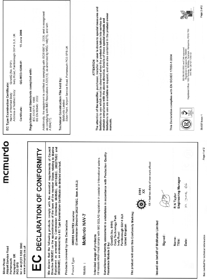
Appendix III: Declaration of Conformity
47
McMurdo Limited Product Warranty
Subject to the provisions set out below McMurdo Limited warrants that this product will be free of defects in
materials and workmanship for a period of 24 months from the date of purchase.
McMurdo Limited will not be liable to the buyer under the above warranty:-
for any defect arising from fair wear and tear, wilful damage, negligence, abnormal working conditions,
failure to follow McMurdo Limited's instructions (whether oral or in writing) including a failure to install
properly and/or to use batteries recommended and/or supplied by McMurdo Limited, misuse or alterations
or repair of the product by persons other than McMurdo Limited or an Approved Service Agent;
for parts, materials or equipment not manufactured by McMurdo Limited in respect of which the buyer shall
only be entitled to the benefit of any warranty or guarantee given by the manufacturer to McMurdo Limited;
for the battery storage life which is specifically excluded from this warranty;
if the total price for the product has not been paid.
THE LIMITED WARRANTY STATED ABOVE IS EXCLUSIVE AND IN LIEU OF ANY OTHER WARRANTY,
EXPRESS OR IMPLIED, INCLUDING BUT NOT LIMITED TO ANY IMPLIED WARRANTY OF
MERCHANTABILITY OR FITNESS FOR A PARTICULAR PURPOSE. McMurdo will not be liable for
indirect, special, incidental or consequential damages of any kind sustained from any cause. In no event
shall McMurdo be liable for any breach of warranty or other claim in an amount exceeding the purchase
price of the product. This warranty does not affect any statutory rights of the consumer.
In order to be valid, claims must be made under the above warranty in writing as soon as practicable after
discovery of the defect or failure and within the warranty period referred to above. Proof of purchase will be
required. The claim should be sent together with the product in question to the address set out below or to
an Approved Service Agent.
Following a valid warranty claim McMurdo Limited shall be entitled to repair or replace the product (or part)
in question free of charge, or at McMurdo Limited's sole discretion to refund to the buyer the price of the
product (or a proportional part of the price). McMurdo Limited shall not be liable to a buyer who is not a
consumer for any other loss or damage (whether indirect, special or consequential loss of profit or
otherwise) costs, expenses or other claims for compensation which arise out of or in connection with this
product. In the case of a consumer McMurdo Limited shall only be liable where other loss or damage is
foreseeable.
Nothing shall limit McMurdo Limited's liability for death or personal injury caused by its negligence.
This warranty is to be interpreted under English law.
All enquiries relating to this warranty or Approved Service Agents should be sent to:
McMurdo Limited
Silver Point, Airport Service Road, Portsmouth, Hampshire, PO3 5PB UK
Telephone: Int + 44 (0) 23 9262 3900
Fax: Int + 44 (0) 23 9262 3998
Web: www.mcmurdo.co.uk
Email: customerservice@mcmurdo.co.uk

48
McMurdo Limited
Silver Point
Airport Service Road
Portsmouth PO3 5PB
United Kingdom
Tel: +44 (0)23 9262 3900
Fax: +44 (0)23 9262 3998
www mcmurdo.co.uk
Email: sales@mcmurdo.co.uk
35-821 Iss1