Orpak Systems 800960000 Fuel Pump Nozzle Reader NNR + Switch User Manual 817460005 Rev A nNR Assembly Guide
Orpak Systems Ltd. Fuel Pump Nozzle Reader NNR + Switch 817460005 Rev A nNR Assembly Guide
Contents
- 1. Users Manual
- 2. User Manual
User Manual
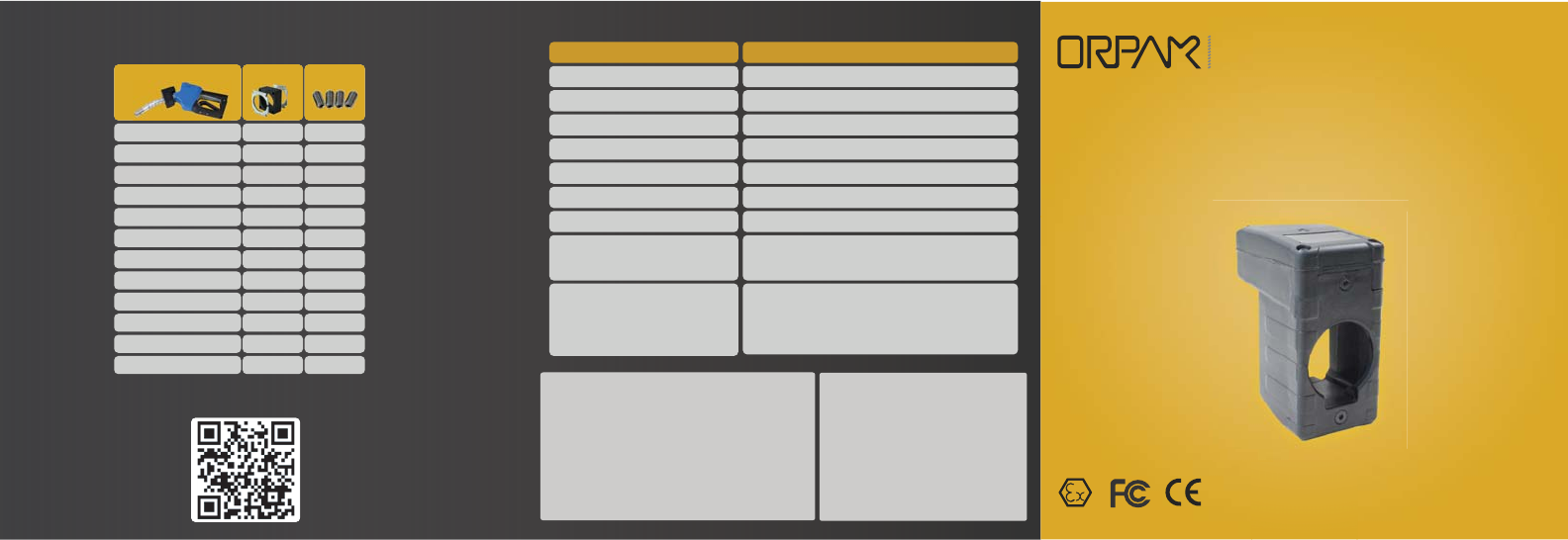
Parameter Value
Supply Voltage 3.6 internal battery pack P/N 812560010
Power Consumption Active Mode: 160mA Standby Mode 20 μA
Operating Temperature -40° to +60° C
Storage Temperature -40° to +85° C
IP Rating IP 67
Dimensions (HxWxD) 41x84x60.5mm
Weight 132g
Communication Interface RF to WGT: 2.405-2.480GHz
Typical transmission power: 3dbm (2mW)
RFID to FuelOpass: 108-131 kHz
Zone 1 Expl osive atmospher e (Ex)
ia (intri nsic safety) protection level
Gr oup IIC type product
TemperatureClass:T6
Rated Tem peratur es:- 40°< Tamb< +60° C
Specifications
The FCC Wants You to Know:
This equipment has been tested and found to comply with the limits for a Class A
& B digital device, pursuant to Part 15 of the FCC rules. These limits are designed
to provide reasonable protection against harmful interference in a residential
installation. This equipment generates uses and can radiate radio frequency
energy and, if not installed and used in accordance with the instructions, may
cause harmful interference to radio communications. However, there is no
guarantee that interference will not occur in a particular installation. If this
equipment does cause harmful interference to radio or television reception, which
can be determined by turning the equipment off and on, the user is encouraged to
try to correct the interference by one or more of the following measures :
a) Reorient or relocate the receiving antenna.
b) Increase the separation between the equipment and receiver.
c) Connect the equipment to an outlet on a circuit different from that to which the
receiver is connected.
d) Consult the dealer or an experienced radio/TV technician.
Changes or modifications to this unit not expressly approved
by the party responsible for compliance could void the user’s
authority to operate the equipment.
This device complies with FCC Rules Part 15 and with
Industry Canada licence-exempt RSS standard(s). Operation
is subject to two conditions:
(1) This device may not cause harmful interference, and (2)
this device must accept any interference that may be
received or that may cause undesired operation.
Le present appareil est conforme aux CNR d'Industrie
Canada applicables aux appareils radio exempts de licence.
L'exploitation est autorisee aux deux conditions suivantes
:(1) l'appareil ne doit pas produire de brouillage, et (2)
l'utilisateur de l'appareil doit accepter tout brouillage
radioelectrique subi, meme si le brouillage est susceptible
d'en compromettre le fonctionnement.
FCC Compliance Statement Warning
Universal Kit
nNR universal kit suits any spout diameter between 22mm and 32mm
as it includes 4 grip kits. Choose your grip kit according to the table below:
Husky 1A 30 6
Husky X 27 6
OPW 11 A/B Leaded 30 6
OPW 11 A/B Unleaded 27 6
OPW Avance HS/VR 32 6
OPW DEF 27 6
Tatsuno Leaded 30 6
Tatsuno Unleaded 27 6
ZVA 25 32 6
ZVA DEF 24 8
ZVA Slim Line 30 6
ZVA S.L. 2-GR 30 6
Nozzle Model Grip Kit** Set Screws*
*Use 10mm set screws when spout diameter is 22mm or below.
** The 32mm grip kit includes only a two-pieces top lid instead of two lids.
FOR SUCCESS
FUELING YOUR BUSINESS
nano Nozzle Reader
Assembly Guide
Hazardous Area
Watch nNR Installation Tutorial
P/N 817460005
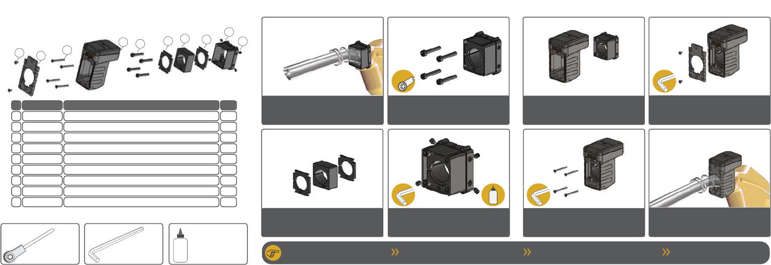
Slide the adaptor over the spout.
Place it as close as possible to the
nozzle body
Choose the proper grip kit for the nozzle
(see rear table). Place a lid, the rubber filler
and then the other lid
Secure the gip kit with the M4 screws.
Tighten them in stages and in a diagonal
sequence. Use a 3mm head ratchet
Apply glue and place the set screws in the
adaptor corners. Use a 2mm Allen key
Slide the nNR assembly over the spout
Secure the nNR to the adaptor with the M3
screws. Use a 2mm Allen key
Place the nNR front cover on top of the
assembly. Secure with the M3 screws.
Use a 2mm Allen key
Installation Kit
1
2
3
4
5
6
7
8
9
1 Set Screws 815221300 (6) 815221380 (8) 815221310 (10)
2 Spout Adaptor 814360500
3 Lids 814360424 (24) 814160427 (27) 814160430 (30) 814360700 (32)
4 Rubber Filler 814160024 (24) 814160027 (27) 814160030 (30) 814160032 (32)
5 M4 Screws 815213424
6 nNR Assembly 819260000 (nNR)/819260100(nNR + Switch)
7 M3 Screws 815260300
8 Front Cover 814360200
9 M3x6 Screws 815260200
# Part Name Part Number
3
Required Tools
2mm standard Allen key
(not ball ended)
3mm Allen head ratchet
(not ball ended)
Loctite 222/
Holdtite T43 glue
Unit should be serviced only by authorized
service personnel.
Program the unit
Opening of the unit by Service Personnel
must not be done at the location of installation.
When replacing the battery,
use only P/N 812560010.
Installation Notes
1
2
3
4
5
6
7
8
3mm
2mm
2mm
2mm
4
1
2
1
4
1
4
1
2
Qty.