Orpak Systems 819507450 uDataPass User Manual

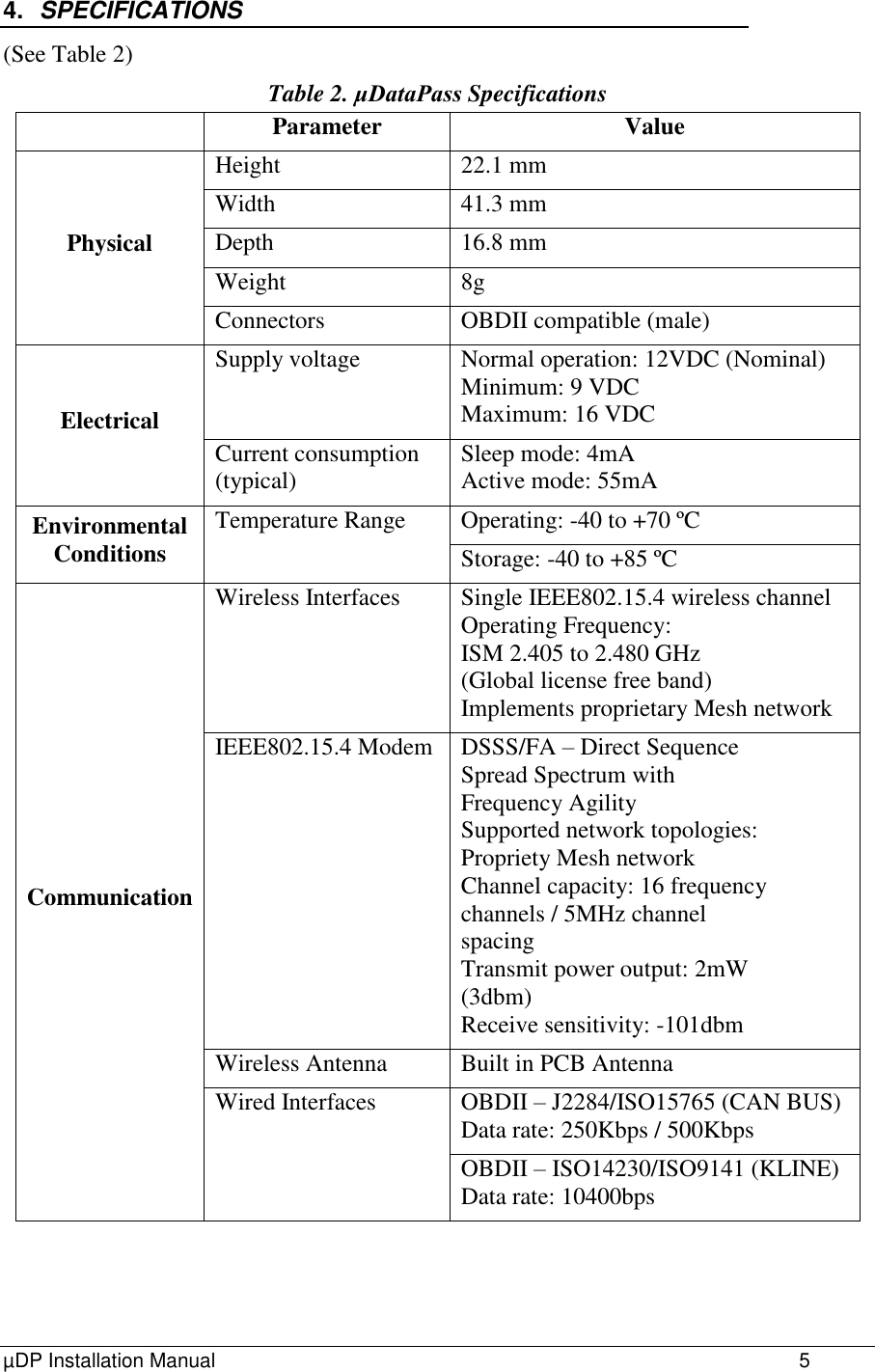
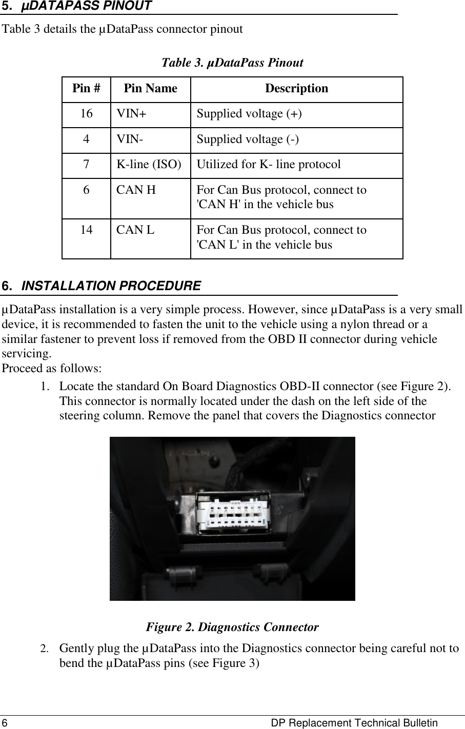
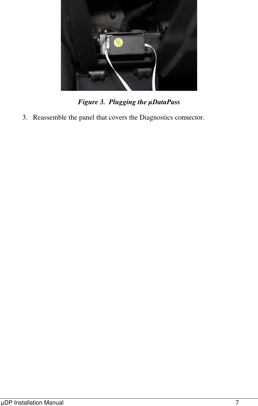
Orpak Systems Ltd. uDataPass Users Manual

Users Manual

  P/N 817407450 Revision A                 FuelOmat Gold  µDataPass Installation Manual
FCC Compliance Statement The FCC Wants You to Know: This equipment has been tested and found to comply with the limits for a Class A & B digital device, pursuant to Part 15 of the FCC rules.  These limits are designed to provide reasonable protection against harmful interference in a residential installation.  This equipment generates uses and can radiate radio frequency energy and, if not installed and used in accordance with the instructions, may cause harmful interference to radio communications.  However, there is no guarantee that interference will not occur in a particular installation.  If this equipment does cause harmful interference to radio or television reception, which can be determined by turning the equipment off and on, the user is encouraged to try to correct the interference by one or more of the following measures : a)  Reorient or relocate the receiving antenna. b)  Increase the separation between the equipment and receiver. c)  Connect the equipment to an outlet on a circuit different from that to which the receiver is connected. d)  Consult the dealer or an experienced radio/TV technician. Warning Changes or modifications to this unit not expressly approved by the party responsible for compliance could void the user’s authority to operate the equipment.  This device complies with FCC Rules Part 15 and with Industry Canada licence-exempt RSS standard(s). Operation is subject to two conditions:  (1) This device may not cause harmful interference, and (2) this device must accept any interference that may be received or that may cause undesired operation.  Le present appareil est conforme aux CNR d'Industrie Canada applicables aux appareils radio exempts de licence. L'exploitation est autorisee aux deux conditions suivantes :(1) l'appareil ne doit pas produire de brouillage, et (2) l'utilisateur de l'appareil doit accepter tout brouillage radioelectrique subi, meme si le brouillage est susceptible d'en compromettre le fonctionnement.  LISTED  XXXX Conforms to UL Std. 60950-1;  Certified to CAN/CSA Std. C22.2 No. 60950-1
µDP Installation Manual                 III  TABLE OF CONTENTS Paragraph Page   1. SCOPE ....................................................................................................... 4 2. GENERAL DESCRIPTION ......................................................................... 4 3. AVAILABLE CONFIGURATIONS .............................................................. 4 4. SPECIFICATIONS ..................................................................................... 5 5. µDATAPASS PINOUT ............................................................................... 6 6. INSTALLATION PROCEDURE .................................................................. 6
4                  µDP Installation Manual 1. SCOPE This document describes the the mechanical installation of Orpak's µDataPass, part of the FuelOmat Gold Wireless Vehicle Identification System. 2. GENERAL DESCRIPTION The µDataPass (see Figure 1) unit collects accurate data from the vehicle on-board computer bus (OBDII) and transmits it to Orpak's Wireless Gateway Terminals (WGT) while refueling, or whenever the vehicle passes next to the WGT installed at the fleet facilities. µDP implements OBDII-CAN, KLINE and M-OBD while reading vehicle bus µDP implements IEEE802.15.4 for transmitting vehicle data to WGT Wireless IEEE802.15.4 uses the ISM 2.4GHz global license free band The unit is powered by vehicle battery.  Figure 1 – µDP, General View 3. AVAILABLE CONFIGURATIONS (See Table 1) Table 1. Available Configurations Unit P/N µDataPass 800907450 µDataPass Plus 800907451
µDP Installation Manual                 5 4. SPECIFICATIONS (See Table 2) Table 2. μDataPass Specifications  Parameter Value Physical Height  22.1 mm Width 41.3 mm Depth 16.8 mm Weight 8g Connectors OBDII compatible (male) Electrical Supply voltage Normal operation: 12VDC (Nominal) Minimum: 9 VDC Maximum: 16 VDC Current consumption (typical) Sleep mode: 4mA Active mode: 55mA Environmental Conditions Temperature Range Operating: -40 to +70 ºC Storage: -40 to +85 ºC Communication Wireless Interfaces Single IEEE802.15.4 wireless channel Operating Frequency:  ISM 2.405 to 2.480 GHz (Global license free band)  Implements proprietary Mesh network IEEE802.15.4 Modem DSSS/FA – Direct Sequence Spread Spectrum with Frequency Agility Supported network topologies: Propriety Mesh network Channel capacity: 16 frequency channels / 5MHz channel spacing  Transmit power output: 2mW (3dbm) Receive sensitivity: -101dbm Wireless Antenna Built in PCB Antenna Wired Interfaces OBDII – J2284/ISO15765 (CAN BUS) Data rate: 250Kbps / 500Kbps OBDII – ISO14230/ISO9141 (KLINE) Data rate: 10400bps
6              DP Replacement Technical Bulletin 5. µDATAPASS PINOUT Table 3 details the µDataPass connector pinout Table 3. µDataPass Pinout Pin # Pin Name Description 16 VIN+ Supplied voltage (+)  4 VIN- Supplied voltage (-)  7 K-line (ISO) Utilized for K- line protocol  6 CAN H For Can Bus protocol, connect to 'CAN H' in the vehicle bus  14 CAN L For Can Bus protocol, connect to 'CAN L' in the vehicle bus  6. INSTALLATION PROCEDURE µDataPass installation is a very simple process. However, since µDataPass is a very small device, it is recommended to fasten the unit to the vehicle using a nylon thread or a similar fastener to prevent loss if removed from the OBD II connector during vehicle servicing.  Proceed as follows: 1. Locate the standard On Board Diagnostics OBD-II connector (see Figure 2). This connector is normally located under the dash on the left side of the steering column. Remove the panel that covers the Diagnostics connector   Figure 2. Diagnostics Connector 2. Gently plug the µDataPass into the Diagnostics connector being careful not to bend the µDataPass pins (see Figure 3)
µDP Installation Manual                 7  Figure 3.  Plugging the μDataPass 3. Reassemble the panel that covers the Diagnostics connector.

Navigation menu