Orpak Systems 819539370 WIRELESS GATEWAY TERMINAL User Manual
Orpak Systems Ltd. WIRELESS GATEWAY TERMINAL Users Manual
Users Manual

No. 817439300
Revision D3
W
WG
GT
T
O
Ou
ut
td
do
oo
or
r
U
Un
ni
it
t
-
-
M
Ma
an
nu
ua
al
l
INSTALLATION

WGT Outdoor Manual
i
SAFETY CONSIDERATIONS
Read all warning notes and instructions carefully. They are included to help you installing the Product safely
in the highly flammable environment of the fuel station. Disregarding these warning notes and instructions
could result in serious injury or property damage. It is the installer responsibility to install, operate and
maintain the equipment according to the instructions given in this manual, and to conform to all applicable
codes, regulations and safety measures. Failure to do so could void all warranties associated with this
equipment.
Remember that the fuel station environment is highly flammable and combustible. Therefore, make sure
that actual installation is performed by experienced personnel, licensed to perform work in fuel station and at
a flammable environment, according to the local regulations and relevant standards.
WARNING - EXPLOSION HAZARD
Install the Product only in the non-hazardous area of the fuel station.
Use standard test equipment only in the non- hazardous area of the fuel station, and approved test equipment
for the hazardous areas.
In the installation and maintenance of the Product, comply with all applicable requirements of the National
Fire Protection Association NFPA-30 “Flammable and Combustible Liquids Code”, NFPA-30A “Automotive
and Marine Service Station Code”, NFPA-70 “National Electric Code”, federal, state and local codes and any
other applicable safety codes and regulations.
Do not perform metal work in a hazardous area. Sparks generated by drilling, tapping and other metal work
operations could ignite fuel vapors and flammable liquids, resulting in death, serious personal injury,
property loss and damage to you and other persons.
CAUTION - SHOCK HAZARD
Dangerous AC voltages that could cause death or serious personal injury are used to power the Product.
Always disconnect power before starting any work. The Product has more than one power supply connection
port. Disconnect all power before servicing.
WARNING – PASSING VEHICLES
When working in any open area of fuel station, beware of passing vehicles that could hit you. Block off the
work area to protect yourself and other persons. Use safety cones or other signaling devices.
CAUTION
Do not attempt to make any repair on the printed circuit boards residing in the Product, as this will void all
warranties related to this equipment.
PROPRIETY NOTICE
This document contains propriety and confidential information. It is the property of ORPAK SYSTEMS
Ltd. It may not be disclosed or reproduced in whole or in part without written consent of ORPAK
SYSTEMS. The information in this document is current as of the date of its publication, but is subject to
change without notice.

WGT Outdoor Manual
ii
DISCLAIMER
This document is provided for reference only. Although every effort has been made to ensure correctness,
ORPAK SYSTEMS does not guarantee that there are no errors or omissions in this document.
FCC COMPLIANCE STATEMENT IN USER'S MANUAL
This device complies with part 15 of the FCC rules. Operation is subject to the following two
conditions:
(1) This device may not cause harmful interference, and
(2) This device must accept any interference received, including interference that may cause
undesired operation.
Sample user information for a Class A digital device:
Sample user information for a Class B digital device
THE FCC WANTS YOU TO KNOW:
This equipment has been tested and found to comply with the limits
or a Class A digital device, pursuant to part 15 of the FCC Rules. These
limits are designed to provide reasonable protection against harmful interference when the
equipment is operated in a commercial environment.
his equipment generates, uses, and can radiate radio frequency energy
and, if not installed and used in accordance with the instruction manual,
ay cause harmful interference to radio communications. Operation of this
equipment in a residential area is likely to cause harmful interference in
which case the user will be required to correct the interference at his
own expense.
FCC Warning
Modifications not expressly approved by the manufacturer responsible could void
the user’s authority to operate the equipment under FCC rules.

WGT Outdoor Manual
iii
This document is the property of:
ORPAK SYSTEMS Ltd.
ISRAEL
THE FCC WANTS YOU TO KNOW:
This equipment has been tested and found to comply with the limits
for a Class B digital device, pursuant to part 15 of the FCC Rules. These
limits are designed to provide reasonable protection against harmful
interference in a residential area.
This equipment generates, uses, and can radiate radio frequency energy
and, if not installed and used in accordance with the instructions,
may cause harmful interference to radio communications. However, there
is no guarantee that interference will not occur in a particular installation.
if this equipment does not cause harmful interference to radio or television
reception, which can be determined by turning the equipment off and on,
the user is encouraged to try to correct the interference by one or more of
the following measures:
Reorient or relocate the receiving antenna
Increase the separation between the equipment and the receiver
Connect the equipment to an outlet on a circuit different from that
to which the receiver is connected
Consult the dealer or an experienced radio/TV technician
FCC Warning
Modifications not expressly approved by the manufacturer responsible
could void the user’s authority to operate the equipment under FCC rules.

WGT Outdoor Manual
iv
TABLE OF CONTENTS
Paragraph Page
SECTION 1
GENERAL DESCRIPTION..........................................................1-1
1-1. WGT – WIRELESS GATEWAY TERMINAL .................................................................. 1-1
1-2. WGT OUTDOOR BOX ............................................................................................... 1-1
1-3. INSTALLATION OPTIONS ............................................................................................... 1-2
1-4. INSTALLATION REQUIREMENTS ................................................................................. 1-2
1-5. INTERNAL POWER SUPPLY ........................................................................................... 1-2
1-6. EXTERNAL POWER SUPPLY .......................................................................................... 1-3
1-7. INSTALLATION LOCATION ........................................................................................... 1-4
1-8. INSTALLATION INSTRUCTIONS ................................................................................... 1-4
1
1-
-8
8.
.1
1.
. I
IN
NS
ST
TA
AL
LL
LA
AT
TI
IO
ON
N
(
(W
WI
IT
TH
H
I
IN
NT
TE
ER
RN
NA
AL
L
P
PO
OW
WE
ER
R
S
SU
UP
PP
PL
LY
Y)
)............................................... 1-5
1
1-
-8
8.
.2
2.
. I
IN
NS
ST
TA
AL
LL
LA
AT
TI
IO
ON
N
(
(E
EX
XT
TE
ER
RN
NA
AL
L
P
PO
OW
WE
ER
R
S
SU
UP
PP
PL
LY
Y)
) ......................................................... 1-8
1
1-
-8
8.
.3
3.
. W
WI
IR
RI
IN
NG
G
a
an
nd
d
L
LE
ED
DS
S
D
DE
ES
SC
CR
RI
IP
PT
TI
IO
ON
N .................................................................................. 1-10
1
1-
-8
8.
.4
4.
. B
BA
AT
TT
TE
ER
RY
Y
R
RE
EP
PL
LA
AC
CE
EM
ME
EN
NT
T ............................................................................................. 1-12
1-9. WGT OUTDOOR BOX SPECIFICATIONS (WITH POWER SUPPLY) ......................... 1-13
1-10. WGT OUTDOOR BOX SPECIFICATIONS (NO POWER SUPPLY).............................. 1-14
1-11. TROUBLESHOOTING 1-15
LIST OF ILLUSTRATIONS
Figure Page
Figure 1-1. WGT - General View 1-1
Figure 1-2. WGT – with Internal Power Supply 1-2
Figure 1-3. WGT – with External Power Supply 1-3
Figure 1-4. WGT, Outdoor Installation Control Drawing 1-4
Figure 1-5. WGT Outdoor Box, Inside View 1-5
Figure 1-6. Terminal Block – Internal View 1-6
Figure 1-7. Gland Holes - General View 1-6
Figure 1-8. WGT Box Cable Installation 1-7
Figure 1-9.WGT - Cover Removed 1-8
Figure 1-10.WGT External Connections 1-9
Figure 1-11. WGT Glands 1-9
Figure 1-12. PCB Battery 1-13
Figure 1-13. WGT Outdoor Box Dimensions 1-15

WGT Outdoor Manual
v
LIST OF TABLES
Table Page
Table 1-1. WGT Board Input Power Pin Assignment 1-10
Table 1-2. RS485 Communication CN12 Pin Assignment 1-10
Table 1-3. CN2 Pin Number Assignment, LAN Communication 1-11
Table 1-4. CN11 Pin Assignment - RS232 Communication 1-11
Table 1-5. Jumpers (Factory default) 1-11
Table 1-6. Indication LEDs on the Left side of PCB (left to right) 1-11
Table 1-7. Indication LEDs on the Right side of PCB (left to right) 1-12
Table 1-1. WGT, Troubleshooting Procedures 1-16

WGT Outdoor Manual
1-1
0
S
SE
EC
CT
TI
IO
ON
N
1
1
G
GE
EN
NE
ER
RA
AL
L
D
DE
ES
SC
CR
RI
IP
PT
TI
IO
ON
N
1
1-
-1
1.
.
W
WG
GT
T
–
–
W
WI
IR
RE
EL
LE
ES
SS
S
G
GA
AT
TE
EW
WA
AY
Y
T
TE
ER
RM
MI
IN
NA
AL
L
The Wireless Gateway Terminal (WGT) is an electronic unit, part of Orpak Wireless Vehicle
Identification Solution (FuelOmat Gold) for vehicle identification based fueling solution for gas
stations. As part of the solution, one or several WGT units are installed in gas stations to form a
wireless network communication data from the vehicle units to the station controller through short
range RF communication (very low power) in the ISM 2.4 GHz band. The number of WGT units
mainly depends on station size and number of dispensers covered. In each station one of the WGTs
is a Master WGT (M-WGT) and it will be connected to the forecourt controller (FCC) via LAN.
The rest of the WGTs in the station do not require LAN connection.
The WGT can be installed in:
On a pole or wall mounted configuration which requires using the WGT Outdoor box (refer to User
Manual P/N 817439300).
1
1-
-2
2.
.
W
WG
GT
T
O
OU
UT
TD
DO
OO
OR
R
B
BO
OX
X
The WGT Outdoor box is made of plastic to allow for uninterrupted passage of the RF signal. The
WGT Outdoor box includes the WGT as shown in Figure 1-1.
There are two types of WGT boxes:
With internal power supply
Without internal power supply
Figure 1-1. WGT - General View
WGT Outdoor Manual
1-2
1
1-
-3
3.
.
I
IN
NS
ST
TA
AL
LL
LA
AT
TI
IO
ON
N
O
OP
PT
TI
IO
ON
NS
S
The preferred installation method depends on the layout and configuration of the gas station.
There are three installation options for the WGT Outdoor Box:
1. Unit mounted on a wall or a pole in the island
2. On a dedicated pole or pedestal
3. Under the station canopy (less recommended due to maintenance convenience).
Any of the above selected methods must comply with UL and EU requirements.
1
1-
-4
4.
.
I
IN
NS
ST
TA
AL
LL
LA
AT
TI
IO
ON
N
R
RE
EQ
QU
UI
IR
RE
EM
ME
EN
NT
TS
S
Due to safety requirements, it is allowed to install a WGT box within a non-hazardous location only
as shown in the control drawing (see Figure 1-4 ). The hazardous location is defined within the
NFPA 70830A.
1
1-
-5
5.
.
I
IN
NT
TE
ER
RN
NA
AL
L
P
PO
OW
WE
ER
R
S
SU
UP
PP
PL
LY
Y
An optional internal power supply can be used to operate the WGT using regular mains voltage.
This option eliminates the need for an external power supply or DC power source.
Figure 1-2. WGT – with Internal Power Supply
Internal
Power
Supply
WGT Outdoor Manual
1-3
1
1-
-6
6.
.
E
EX
XT
TE
ER
RN
NA
AL
L
P
PO
OW
WE
ER
R
S
SU
UP
PP
PL
LY
Y
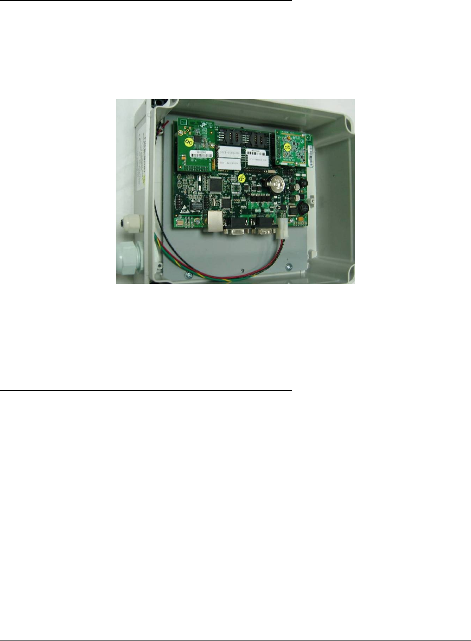
If an external PS is used to operate the WGT, a unit with no PS is available. The power supply
should provide 12V to 28V DC output and should be approved according to the local regulation. In
North America use only AC to DC NEC Class 2 power supply, low voltage and low current
maximum 100 VA even under fault conditions. The power supply can be installed in the office, in a
separate box object to requirements in NFPA 70 830A and approval of authority having jurisdiction
(AHJ) DC cable will be connected to the DC input in the WGT box.
Figure 1-3. WGT – with External Power Supply
Note: If the power supply is not installed next to the WGT box, make sure that the WGT receives a
correct voltage (at least 12V) due to power fail on the lines. It is recommended that the distance
between the power supply and the WGT box will not exceed 15m (50 feet).
1
1-
-7
7.
.
I
IN
NS
ST
TA
AL
LL
LA
AT
TI
IO
ON
N
L
LO
OC
CA
AT
TI
IO
ON
N
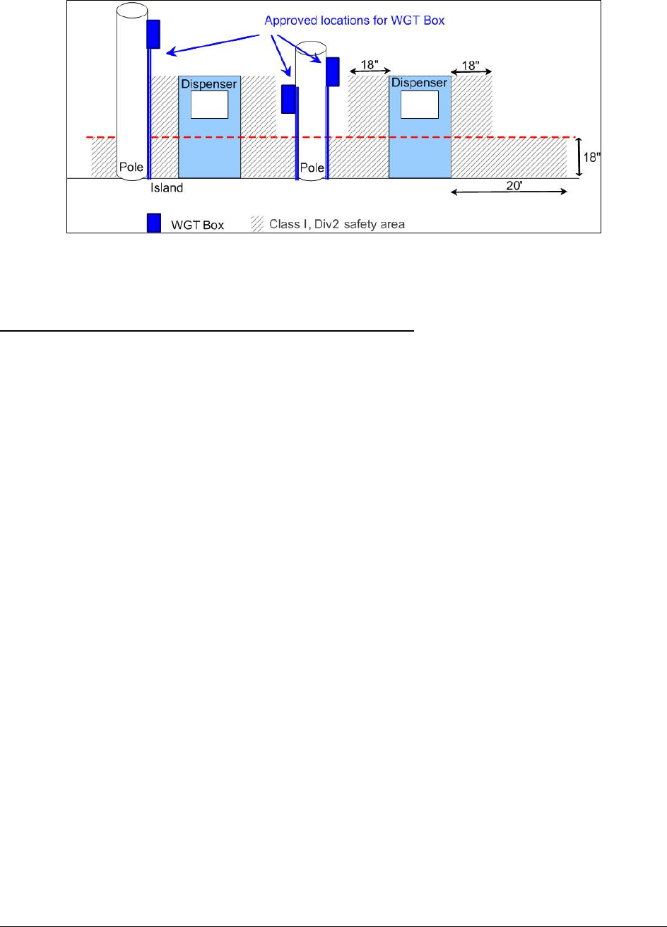
The WGT box must be installed at non hazardous area / non classified area, which means:
1. Above 18” (0.5 meter) from the island floor
2. At least 18” (0.5 meter) away from the dispenser
Figure 1-4 presents various possible WGT Box installation locations.
WGT Outdoor Manual
1-4
Figure 1-4. WGT, Outdoor Installation Control Drawing
1
1-
-8
8.
.
I
IN
NS
ST
TA
AL
LL
LA
AT
TI
IO
ON
N
I
IN
NS
ST
TR
RU
UC
CT
TI
IO
ON
NS
S
The following paragraph provides step by step instructions for installation of the Outdoor WGT.
a. Install the WGT in a non hazardous area according to Figure 1-4.
b. Install the Master WGT and other WGTs in each station according to station topology.
• The Master WGT, as opposed to the other WGTs, is connected to the FCC controller using
shielded S-CAT5E LAN cable. Install the master WGT as close as possible to the FCC
controller.
• Install the WGT in a line of sight with the Master WGT or other WGT/s, within a distance not
exceeding 15 meters (approximately 50 feet).
• For ease of maintenance, it is recommended not to install the WGT higher than two meters from
the ground. However, the higher the unit will be, the better will be the RF cover.
• The installation procedures must meet all safety regulations according to local state regulations.
• For UL listed WGT, All wiring to device must be in UL Listed rigid metal conduit or other
methods permitted in NFPA 70 or NFPA 30A determined acceptable by the authority having
jurisdiction
• For non-UL WGT, glands are provided for the power and data holes
WGT Outdoor Manual
1-5
1
1-
-8
8.
.1
1.
.
I
IN
NS
ST
TA
AL
LL
LA
AT
TI
IO
ON
N
(
(W
WI
IT
TH
H
I
IN
NT
TE
ER
RN
NA
AL
L
P
PO
OW
WE
ER
R
S
SU
UP
PP
PL
LY
Y)
)
- Remove the WGT cover and install the unit on a smooth surface using four screws via holes
located at the four corners of the unit.
- Refer to Figure 1-13 for the location of the four holes.
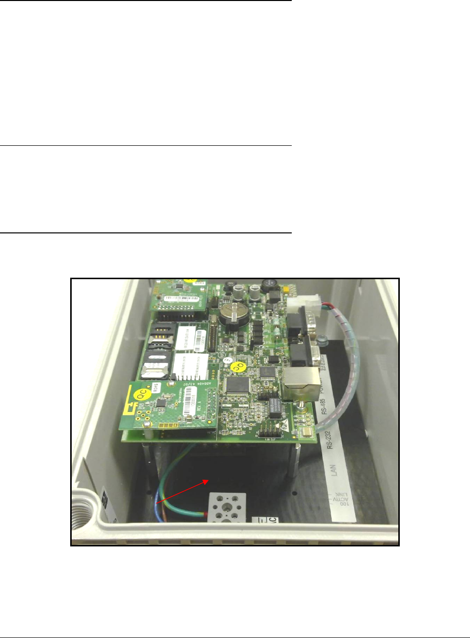
- Install the WGT vertically where the two cable holes are located at the bottom section of the
unit (see Figure 1-5). Failure to install in required orientation may resolve in water leakage
into enclosure
- The WGT has an internal power supply that requires 220VAC/115VAC input.
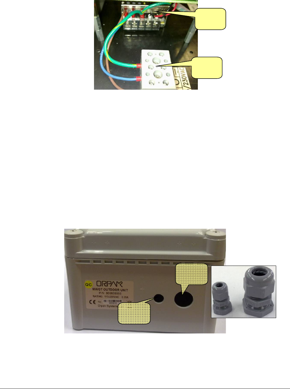
- The input to the internal power supply passes through a terminal block that has three input
connections as specified below:
Yellow – GND
Blue – Neutral
Brown – 220/115VAC
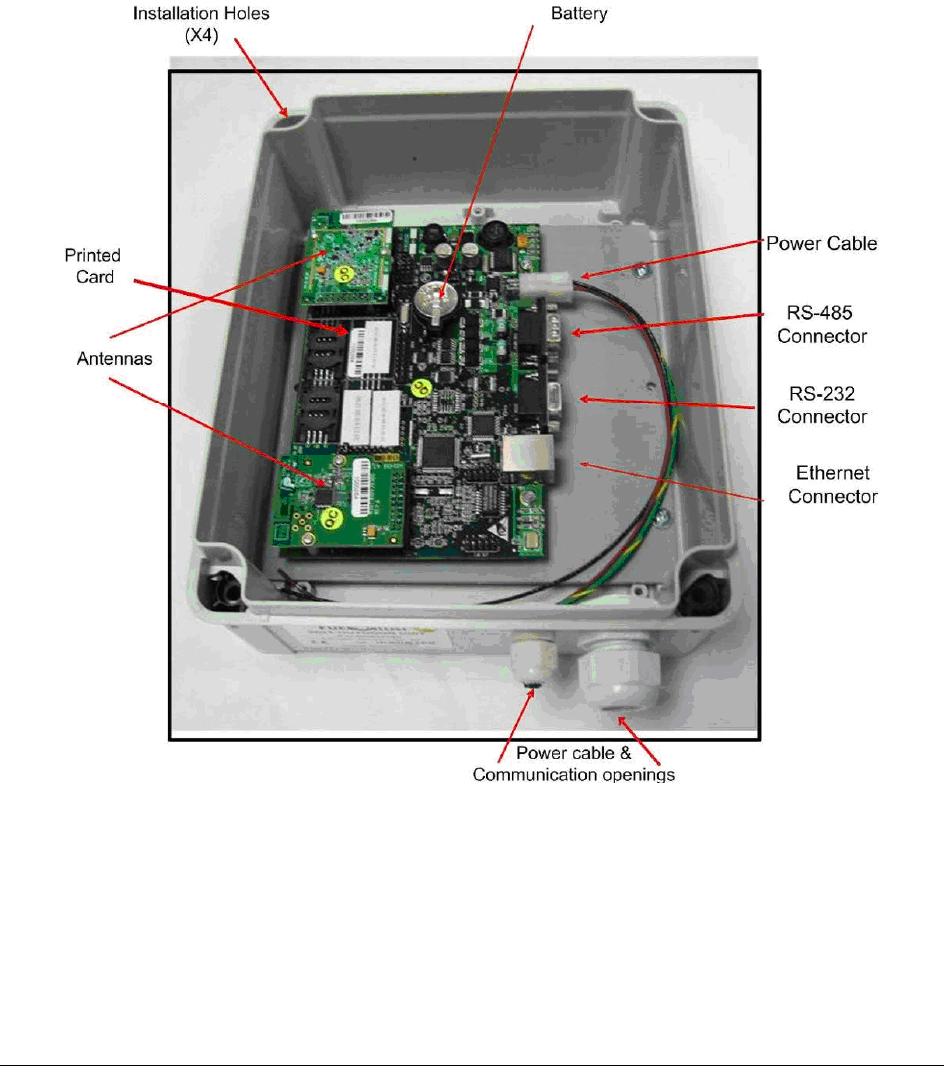
Figure 1-5. WGT Outdoor Box, Inside View
Antenna
Antenna
Installation
Hole (x4)
Ethernet
Connector
WGT
Module
Battery
RS-232
Connector
DC Power
Cable
RS-485
Connector
Terminal
Block
WGT Outdoor Manual
1-6
- Connect the AC cables through the power terminal.
Figure 1-6. Terminal Block – Internal View
- For the Master WGT, connect a shielded S-CAT5E cable using RJ-45 connector.
- For UL listed units, all wiring to device must be in UL Listed rigid metal conduit or other
methods permitted in NFPA 70 or NFPA 30A determined acceptable by the authority having
jurisdiction.
The large hole can host conduits up to 23mm (0.9”) in diameter between and the
small hole can host conduits up to 12mm (0.47”). Upon final installation, both holes of
enclosure bottom must be connected to conduit.
For non-UL units, use the provided couplers (glands). The large hole can host a coupler for
cables in diameter between 0.23” to 0.53” (5.8 to 13.9mm) while the smaller coupler for
cables in diameter between 0.114” to 0.25” (2.9 to 6.4mm).
-
Figure 1-7. Gland Holes - General View
Gland
Hole
Gland
Hole
Terminal
Block
Power
Supply
WGT Outdoor Manual
1-7
- Tighten the glands in order to prevent leak of water or gasses through conduits, cables and
conductors.
- In cases where you are not using one of the two enclosure cables entry be sure to seal it
properly.
- When installing cables into the WGT box, do not damage unit sealing (IP67 protection).
- Assemble the unit cover using the four coarse pitch screws and than install the four screw
clip-on knobs.
• Perform WGT initial setup prior to installation according to instructions provided in the
FuelOmat Gold station installation and setup guide.
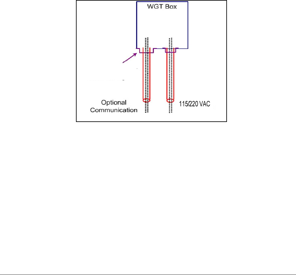
Use cable glands
Or metal conduits
Figure 1-8. WGT Box Cable Installation
WGT Outdoor Manual
1-8
1
1-
-8
8.
.2
2.
.
I
IN
NS
ST
TA
AL
LL
LA
AT
TI
IO
ON
N
(
(E
EX
XT
TE
ER
RN
NA
AL
L
P
PO
OW
WE
ER
R
S
SU
UP
PP
PL
LY
Y)
)
-
Remove the WGT cover (see Figure
1-9) and install the unit on a smooth surface using four
0.2" screws via holes located at the four corners of the unit.
-
Refer to Figure
1-13 for the location of the four holes.
-
Install the WGT vertically where the two cable holes are located at the bottom section of the
unit (see Figure
1-5).
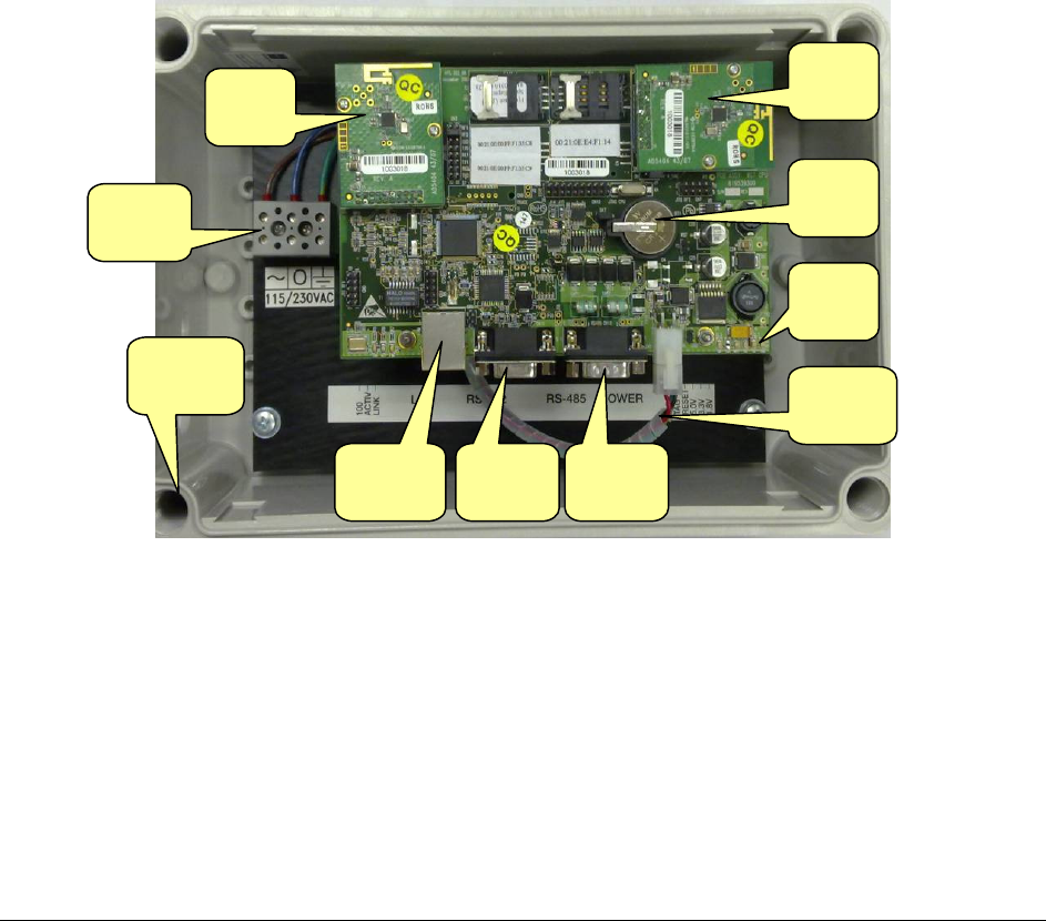
Figure 1-9.WGT - Cover Removed
-
Connect leads from an external power supply for the Master WGT and WGTs to the flying
leads inside the enclosure as specified in Table
1-1):
-
For the master WGT, connect a shielded S-CAT5E cable using RJ-45 connector, as shown
in Figure
1-10.
WGT Outdoor Manual
1-9
Figure 1-10.WGT External Connections
-
For UL listed units, all wiring to device must be in UL Listed rigid metal conduit, or other
methods permitted in NFPA 70 or NFPA 30A determined acceptable by the authority having
jurisdiction.
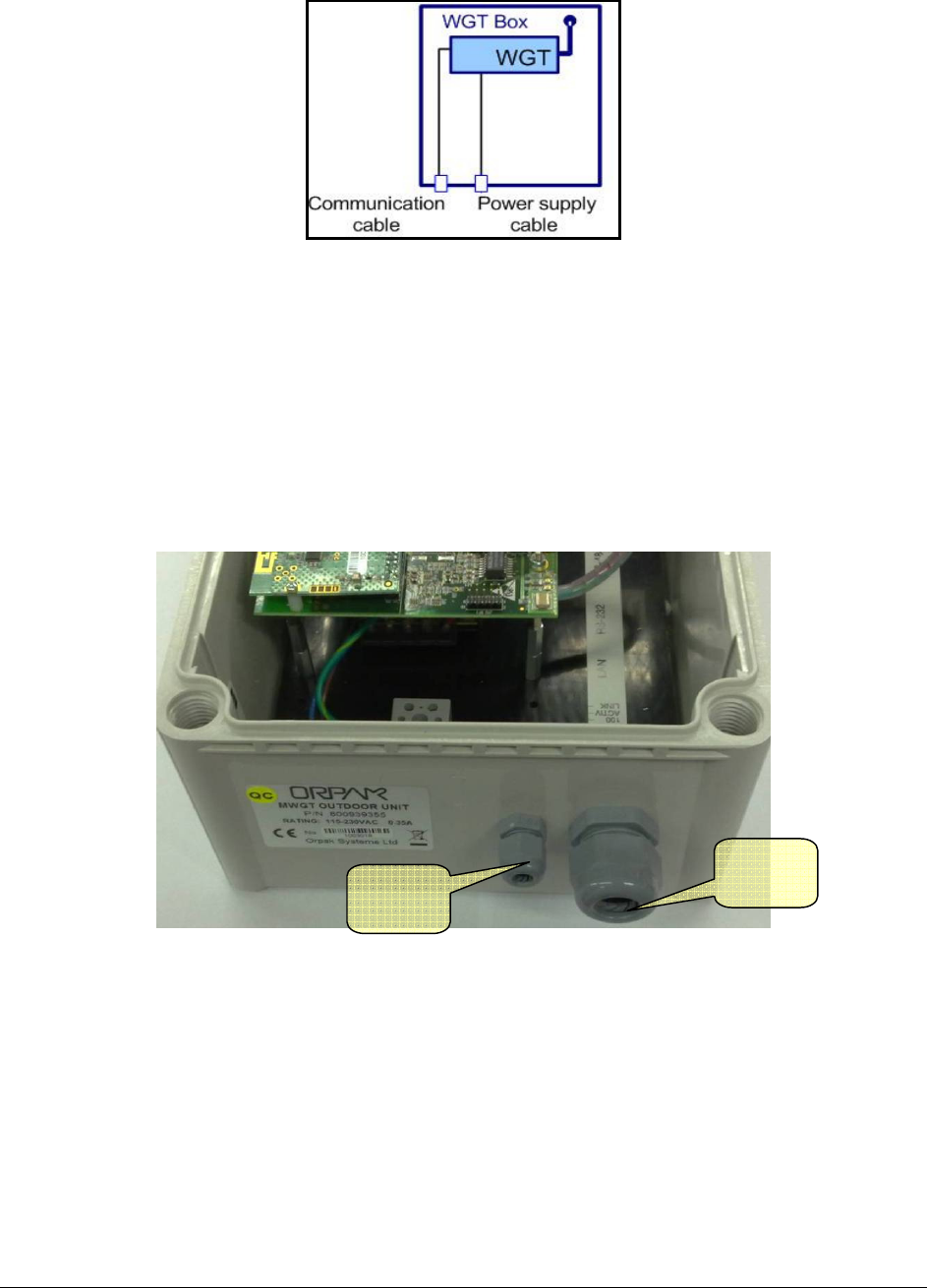
The large hole can host conduits up to 23mm (0.9”) in diameter between and the
small hole can host conduits up to 12mm (0.47”).
-
For non-UL units, use the provided couplers (glands). The large hole (see Figure
1-11) can
host a coupler for cables in diameter between 0.23” to 0.53” (5.8 to 13.9mm) while the
smaller coupler for cables in diameter between 0.114” to 0.25” (2.9 to 6.4mm).
Figure 1-11. WGT Glands
-
Tighten the glands to prevent leak of water / gasses through conduits, cables and conductors.
-
In cases where you are not using one of the two wiring holes be sure to seal it properly.
-
When installing cables into the WGT box, do not damage unit sealing (IP67 protection).
-
Assemble the unit cover using the four coarse pitch screws and than install the four screw
clip-on knobs.
Gland
Gland

WGT Outdoor Manual
1-10
-
Perform WGT setup prior to installation according to instructions provided in the FuelOmat
Gold Station installation and setup guide.
1
1-
-8
8.
.3
3.
.
W
WI
IR
RI
IN
NG
G
a
an
nd
d
L
LE
ED
DS
S
D
DE
ES
SC
CR
RI
IP
PT
TI
IO
ON
N
The WGT Box has power input and optional data (LAN or other) input/output. The LAN cable will
be connected to the station network LAN only in cases where the WGT is a Master WGT.
In cases where a station does not have LAN connection, the RS485 can be used to interface the
station controller instead of the LAN. The other I/O plugs (RS-232 and RS-485) will be connected
only by certified technician for maintenance use only.
The cables must be placed in dedicated tubes which comply with UL/EU regulations and any other
local regulations. The cables enter the WGT box from the sealing adapters which used to ensure the
box sealing as shown in Figure
1-8.
Table 1-1. WGT Board Input Power Pin Assignment
Pin No. Assignment Wire color Remarks
4 DC INPUT +V Red
2 DC INPUT -V Black
1 Ground Yellow/Green Ground connection to be
connected to nearest ground.
3 PF Not used
Table 1-2. RS485 Communication CN12 Pin Assignment
Pin No. Assignment
Channel
1
1
+485
2
-
485
6
G485
Channel 2
3
+485
4
-
485
8
G485
7,
9, case
Ground
5
N.C.

WGT Outdoor Manual
1-11
Table 1-3. CN2 Pin Number Assignment, LAN Communication
Pin No. Assignment
Wire color Remarks
Standard cable S-CAT5E For master WGT application only
Table 1-4. CN11 Pin Assignment - RS232 Communication
Pin No. Assignment Remarks
2
TXD_232
3
RXD_232
4
MONITOR
5
Ground_232
7
CAN_H
8
CAN_L
(MONITOR in old HW version)
9
CAN Ground
1, 6
N.C.
Table 1-5. Jumpers (Factory default)
Only authorized technicians are allowed to modify the jumpers!
Jumper No. Name Description
J2 Watch Dog
J3 Reset
J4/ Pins1-2 3.3V SAM power is 3.3V
J4/ Pins2-3 5V SAM power is 5V
J6 Switches the battery (BT1) to circuit
Table 1-6. Indication LEDs on the Left side of PCB (left to right)
LED No. Name Description
DL2 100 Indicates communication rate:
Light on: 100 BPS
Light off: 10 BPS
DL3 ACT Blinks during active communication
DL4 LNK Illuminates constantly when Ethernet
communication is connected

WGT Outdoor Manual
1-12
Table 1-7. Indication LEDs on the Right side of PCB (left to right)
LED No. Name Description
DL9 GP Illuminates constantly.
Blinks during data transfer via external
communication (Ethernet, RS-232 or RS-485)
DL(not shown) TAG Not used
DL(not shown) RST Reset LED. Illuminates during reset.
DL(not shown) 5V Indicates +5V active
DL7 3V Indicates +3.3V active
DL8 1V8 Indicates +1.8V active
1
1-
-8
8.
.4
4.
.
B
BA
AT
TT
TE
ER
RY
Y
R
RE
EP
PL
LA
AC
CE
EM
ME
EN
NT
T
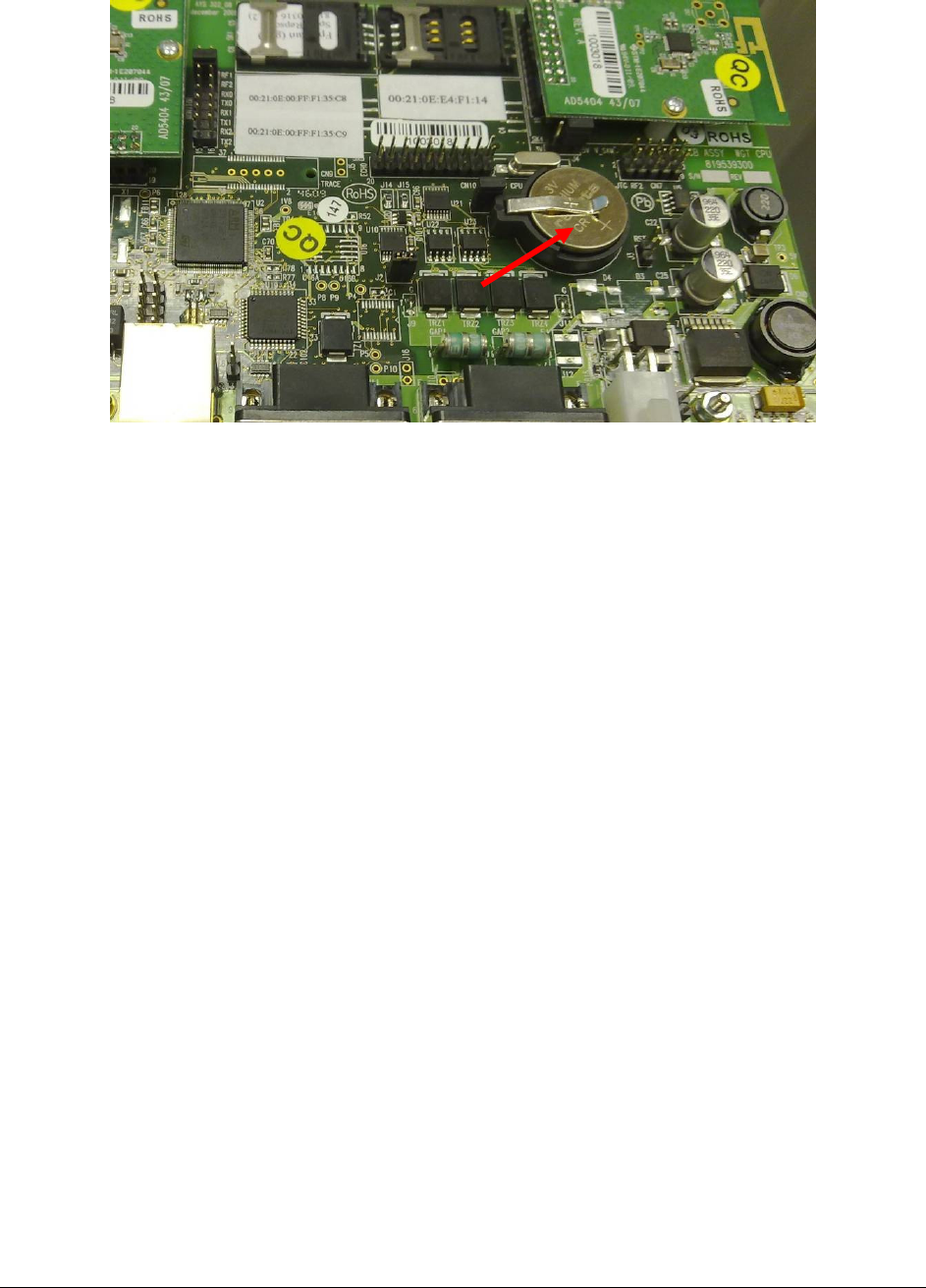
The WGT has a Lithium battery (BT1) for RTC (Real Time Clock) backup. (Orpak P/N
812502030).
To remove battery for disposal:
−
The WGT battery is designed for easy removal and replacement by customers.
−
Read and use any precautions published by battery manufacturer in datasheet/website
concerning battery storage, use and disposal.
−
Make sure the WGT is disconnected from power before removing battery.
−
Remove WGT cover by loosening the screws.
−
Remove the battery from the socket (see Figure
1-12) and replace it with a new one. Replacing
the battery should be done with the same type of battery p/n & manufacturer due to operating
temperature and abnormal charging current.
−
Replace only with battery Part No. CR2032 made by RENATA.
WGT Outdoor Manual
1-13
Figure 1-12. PCB Battery
−
Discharged Lithium and Lithium Ion batteries are currently designated to be disposed off in
normal trash.
−
Battery Disposal must be done in accordance to the manufacturer instructions of the battery!.
−
After battery replacement, return the WGT cover, close it and tighten the screws.

WGT Outdoor Manual
1-14
1
1-
-9
9.
.
W
WG
GT
T
O
OU
UT
TD
DO
OO
OR
R
B
BO
OX
X
S
SP
PE
EC
CI
IF
FI
IC
CA
AT
TI
IO
ON
NS
S
(
(W
WI
IT
TH
H
P
PO
OW
WE
ER
R
S
SU
UP
PP
PL
LY
Y)
)
PARAMETER VALUE
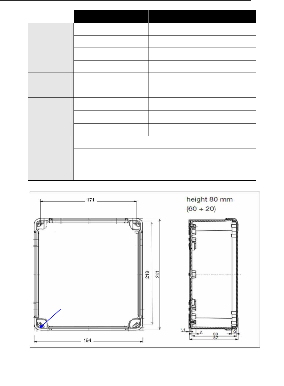
Height – 241 mm
Width – 194 mm
Depth – 87 mm
Physical
Weight – (with / without P/S) 1.6Kg
DC output voltage 12V to 28V DC
Rated current 0.35A
Current range 0~0.625A
Rated power 15W
Voltage tolerance 1.0%
Line regulation 0.5%
Power Supply
data
Load regulation 0.5%
Input voltage range 85~264VAC
Frequency range 47~63Hz
Power Supply
input AC current (typ.) 0.35A/115VAC
0.25A/230VAC
Working Temperature -40°C to +55
0
C
Environment Humidity 20~90% non-condensing
TCP/IP over Ethernet
EIA 802.15.4
Communication
2.4GHz ISM band RF Network Communication with AES128
encryption
WGT Outdoor Manual
1-15
1
1-
-1
10
0.
.
W
WG
GT
T
O
OU
UT
TD
DO
OO
OR
R
B
BO
OX
X
S
SP
PE
EC
CI
IF
FI
IC
CA
AT
TI
IO
ON
NS
S
(
(N
NO
O
P
PO
OW
WE
ER
R
S
SU
UP
PP
PL
LY
Y)
)
PARAMETER VALUE
Height – 241 mm
Width – 194 mm
Depth – 87 mm
Physical
Weight – 0.8 Kg
Operating voltage 12 - 28 V DC
Power Operating current 0.5 A
Working temperature -40°C to +55
0
C
)
Storage temperature -40°C to +55
0
C
)
Environment
Humidity 95% RH
TCP/IP over Ethernet
EIA 802.15.4
Communication
2.4GHz ISM band RF Network Communication with AES128
encryption
Figure 1-13. WGT Outdoor Box Dimensions
Installation
holes (x4)

WGT Outdoor Manual
1-16
1
1-
-1
11
1.
.
T
TR
RO
OU
UB
BL
LE
ES
SH
HO
OO
OT
TI
IN
NG
G
Table
1-1 lists the recommended procedures for troubleshooting the WGT.
Note that this Troubleshooting guide refers to installation issues only! For the full Troubleshooting
guide refer to Orpak's "Station Installation and Setup Manual for New Deployments" User Guide,
Cat. No. 817439320.
Table 1-1. WGT, Troubleshooting Procedures
No.
Symptom Troubleshooting Procedure Recommended Action
Check DC Voltage power supply
output
Replace DC Voltage power
supply
Check AC and DC output Replace power supply
Check the proper connection between
the Power Supply and the WGT
Wire the units anew
1
LEDs inactive
Check fuse Replace fuse (equal to or less
than 3.2A)
2
No communication
between the Master
WGT and the FCC
Check CAT-5E cable connection
between the Master WGT and the FCC
Check 'ping' between FCC and WGT
Check WGT communication settings
Replace one unit, then other units
if necessary
Set the WGT IP address
Perform settings anew
No RF communication Check Wireless Nozzle Reader setup Replace Wireless Nozzle Reader
3
Check WGT setup Set WGT anew
4
No data received from
vehicles
Verify that vehicle units are active (via
the Wireless Programmer)
Check SAM cards are well sited
Check WGT settings
Replace vehicle unit if necessary
Replace SAM cards if necessary