Ott Hydromet Business Unit Adcon Telemetry A725 Telemetry transceiver User Manual
Adcon Telemetry GmbH Telemetry transceiver
UserManual.wiki
>
Ott Hydromet Business Unit Adcon Telemetry
>
A725 User Manual
User manual
Navigation menu
Upload a User Manual
Namespaces
Wiki Guide
HTML
PDF
Info
Views
User Manual
Discussion / Help
Navigation

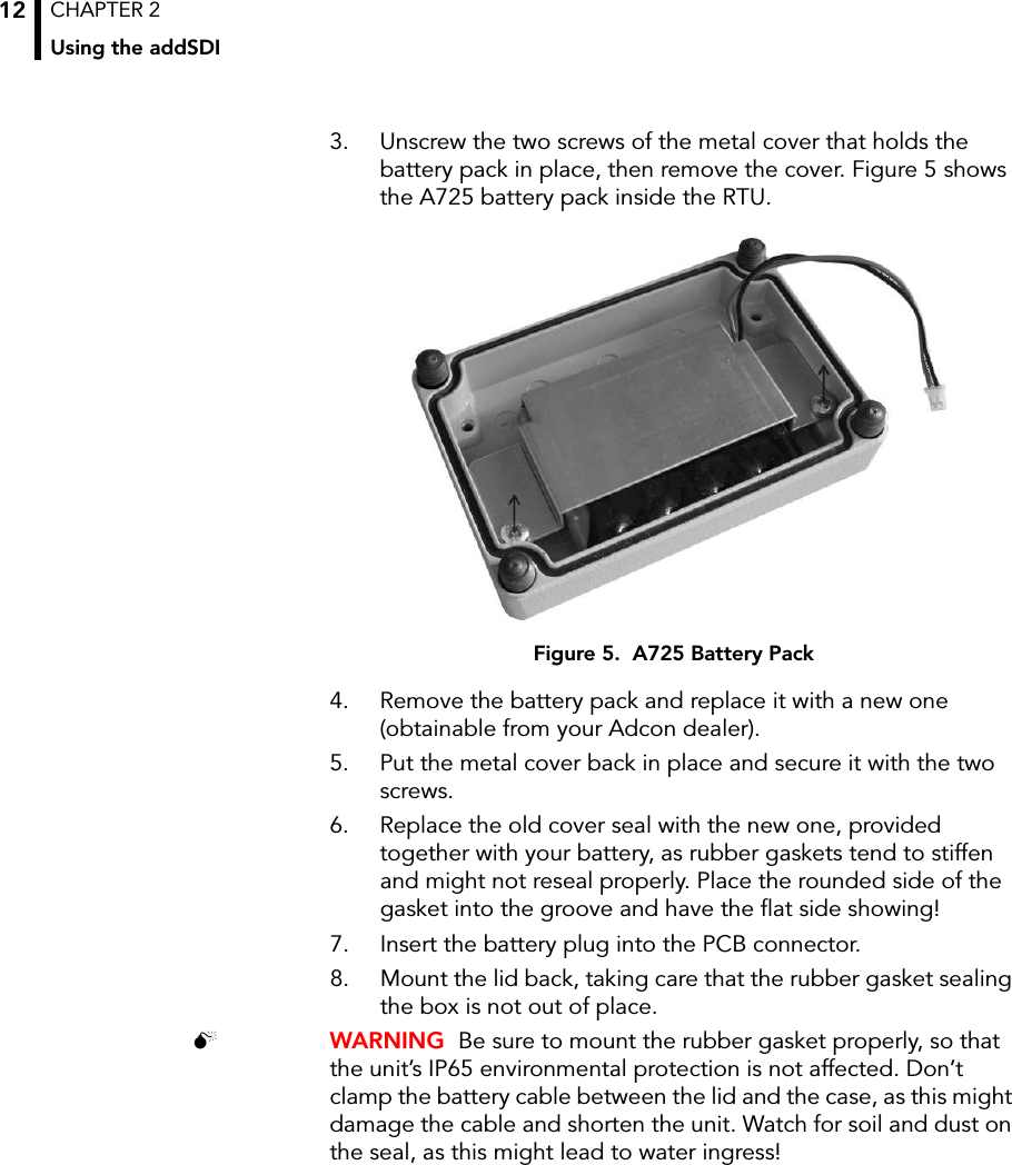
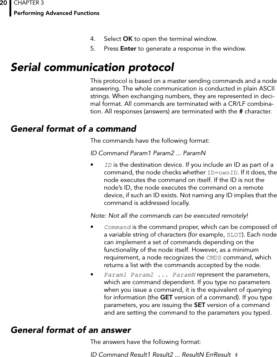
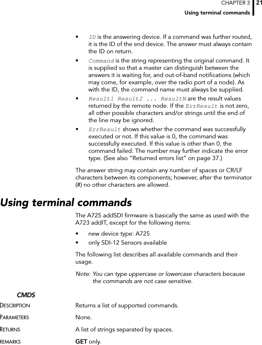
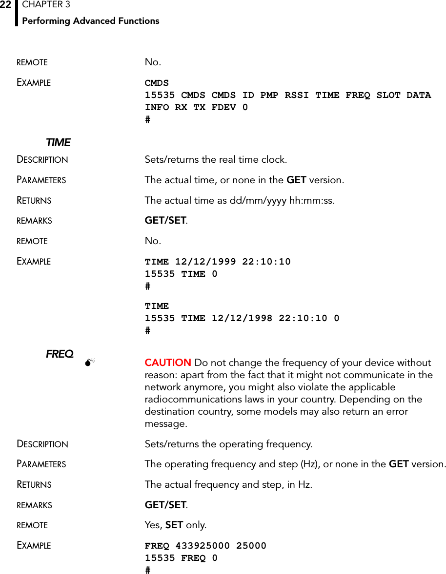
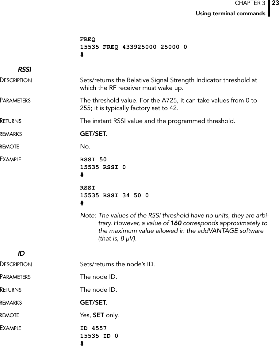
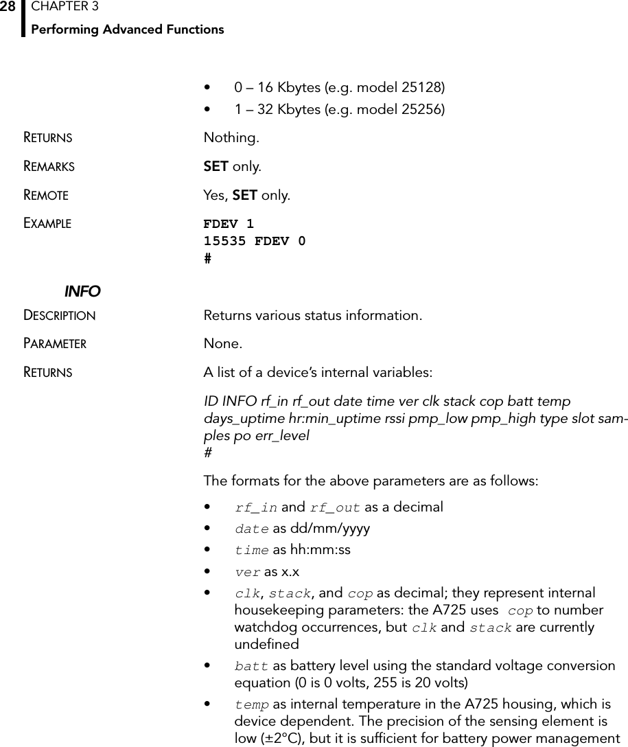
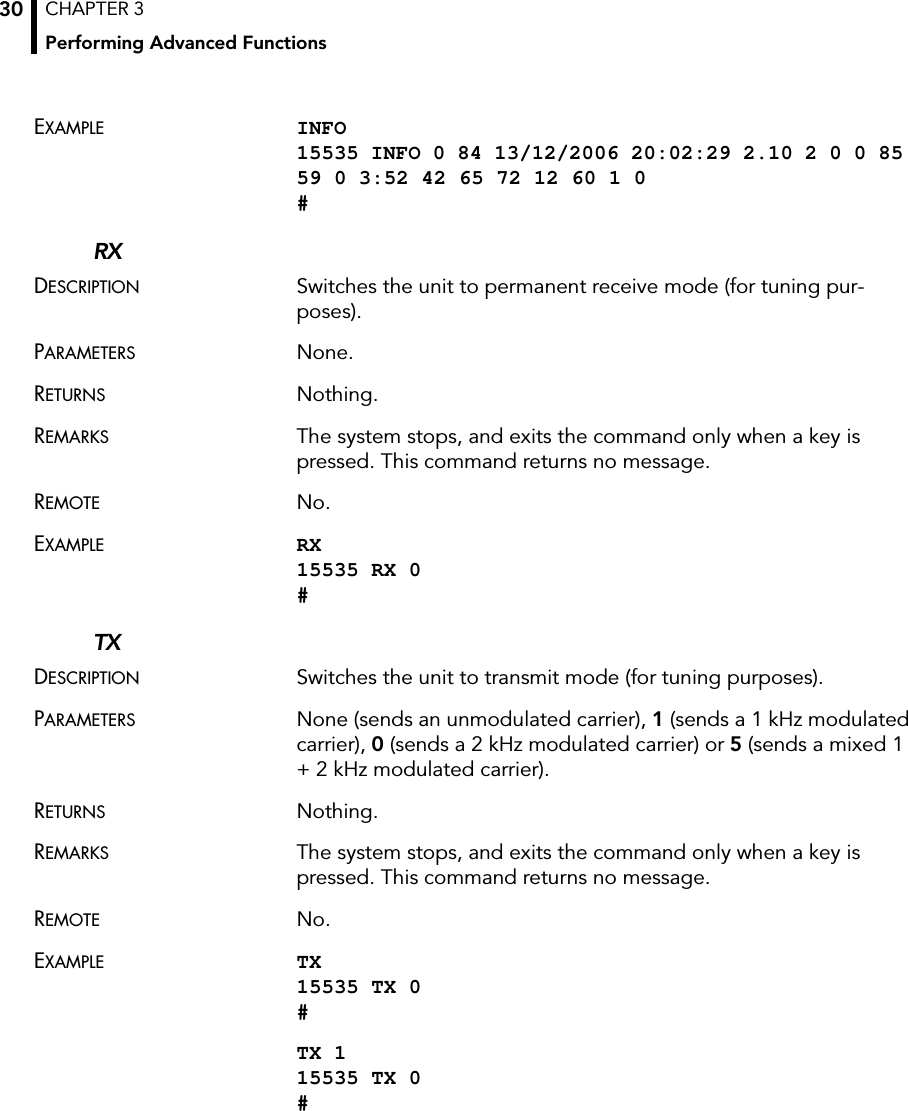
![CHAPTER 3Using terminal commands29(charge/discharge). To compute the actual value (in °C), the following equation must be used:•days_uptime in days; together with hr:min_uptime, it represents the amount of time the device is up without a reset or watchdog•hr:min_uptime in hours:minutes format•rssi as decimal; it is the value programmed with the RSSI command •pmp_low and pmp_high are the programmed values with the PMP command )•type is used to represent the device type; the following types are currently assigned: — 0 for A730MD — 1 for A720 — 2 for A730SD — 3 for A720B — 4 for A733 — 5 for A723 — 6 for A440 — 7 for A733GSM — 8 for A731 — 9 for A732 — 10 for A740 — 11 for A740GSM — 12 for A724 — 13 for A725 — 14 for A726 slot and samples are the actual values programmed by means of the SLOT command•po is the power output of the device during the last frame sent•err_level is the error value; 0 means no errorREMARKS GET only.REMOTE Yes, GET only. The A725 can issue the command both remotely and locally.Temp °C[ ] internalTemp 400⋅255------------------------------------------------- 68–=](https://usermanual.wiki/Ott-Hydromet-Business-Unit-Adcon-Telemetry/A725/User-Guide-753799-Page-31.png)