Ott Hydromet Business Unit Adcon Telemetry A725 Telemetry transceiver User Manual
Adcon Telemetry GmbH Telemetry transceiver
User manual

A725 addSDI
User Manual
SMART WIRELESS SOLUTIONS

Proprietary Notice:
The Adcon logo, addSDI™, addIT™, addWAVE™, addVANTAGE™, addVANTAGE Profes-
sional™ and AgroExpert™ are trademarks or registered trademarks of Adcon Telemetry. All
other registered names used throughout this publication are trademarks of their respective own-
ers.
Neither the whole nor any part of the information contained in this publication may be repro-
duced in any material form except with the prior written permission of Adcon Telemetry.
This publication is intended only to assist the reader in the use of the product. Adcon Telemetry
shall not be liable for any loss or damage arising from the use of any information in this publica-
tion, or any error or omission in such information, or any incorrect use of the product.
Document Release 1.0, Dezember 2006
Copyright ©2003-2006 by Adcon Telemetry.
ADC NO
T E L E M E T R Y
ADCON TELEMETRY GMBH
I N K U S T R A S S E 2 4
A-3400 KLOSTERNEUBURG
A U S T R I A
TEL: +43 | 2243 | 38280-0
FAX: +43 | 2243 | 38280-6
h t t p : / / w w w . a d c o n . a th t t p : / / w w w . a d c o n . a t
2050 LYNDELL TERRACE
S U I T E 1 2 0
C A - 9 5 6 1 6 D A V I S , U S A
TEL: +1 | 530 | 753-1458
FAX: +1 | 530 | 753-1054
h t t p : / / w w w . a d c o n . a th t t p : / / w w w . a d c o n . a t
ADCON INTERNATIONAL INC
ENFIELD PLAZA SA 5058
P O B O X 6 0 5
A D E L A I D E A U S T R A L I A
TEL: +61 | 8 | 8260-4682
FAX: +61 | 8 | 8260-4685
h t t p : / / w w w . a d c o n . a th t t p : / / w w w . a d c o n . a t
ADCON AUSTRALIA PTY. LTD.

CHAPTER 1
About the A725 addSDI___________________________________________________3
Conventions _____________________________________________________________4
Opening the packages____________________________________________________5
Installing the RTU ________________________________________________________6
Field Installation_______________________________________________________7
More about the LED tool _______________________________________________8
Configuring an addSDI RTU in the addVANTAGE software__________________9
Maintaining and servicing the RTU__________________________________________9
The RTU battery_______________________________________________________9
Changing the battery ________________________________________________ 10
Understanding connectors_______________________________________________ 14
The POWER Connector ______________________________________________ 14
The SDI Connector __________________________________________________ 15
SDI-12 Sensor Connections______________________________________________ 16
Self powered Sensor _________________________________________________ 17
Multiple Sensors connected to the SDI-12 Bus __________________________ 18
Communicating with the RTU ____________________________________________ 18
Serial communication protocol ___________________________________________ 19
General format of a command ________________________________________ 19
General format of an answer __________________________________________ 20
Using terminal commands _______________________________________________ 20
Returned errors list _____________________________________________________ 37
Command line interpreter ____________________________________________ 37
Device descriptors and storage handler ________________________________ 37
Real time clock ______________________________________________________ 37
Radio interface ______________________________________________________ 37
Specifications _________________________________________________________ 39

CHAPTER
2

CHAPTER 1
About the A725 addSDI
3
Chapter 1. Introduction
This manual explains the hardware aspects of Adcon’s A725
addSDI Remote Telemetry Units, including installation issues and
certain parameter configurations. The manual is divided as follows:
• "Introduction," which contains some general information and
document conventions.
• "Using the A725 RTU," which details the installation and use
of the Remote Telemetry Unit.
• "Specifications," which describes operating parameters for the
devices.
About the A725 addSDI
The A725 Remote Telemetry Unit—RTU (commercial trademark
addSDI™
) is a low power, short range telemetry device, capable of
operating SDI-12 compatible sensors.
The frequency of operation is in the 432 to 470 MHz range, mak-
ing it compliant to most radio communication regulations in the
world. The output power is under 10 mW, while the modulation is
narrow band FM (12.5 or 25 kHz channel spacing).
Due to its construction, as well as to the software controlling it, the
power consumption is extremely low. The unit operates from a
built in 6.2 Volt rechargeable battery, which is charged either using
a solar panel or an external power supply adapter. A special con-
figuration may be implemented where no internal battery is used,
but the power is obtained exclusively over an external connector.
The SDI-12 bus is also powered by the internal 6.2 Volt battery,
therefore the attached SDI-12 sensors must be able to work within

CHAPTER 1
Introduction
4
a minimum voltage of 5.6V. This is lower than the official SDI-12
minimum operating voltage.
The A725 is a ruggedized unit, complying with the IP65 environ-
mental protection class (NEMA 4). It can easily be installed and it
integrates perfectly into an Adcon A733 network. Depending on
the terrain, it assures a reliable wireless connection to an A733
series device to distances up to 1000 meters, under favorable con-
ditions even more.
Conventions
Certain conventions apply in this document.
Italics
Indicate that the text is variable and must be substi-
tuted for something specific, as indicated in the expla-
nation. Italics can also be used to emphasize words as
words or letters as letters.
Bold Indicates special emphasis of the text. Also indicates
menu names and items in a window.
fixed font Indicates characters you must type or system mes-
sages.
FileSave Indicates menu selection. For example, select the File
menu, then the Save option.
Note Indicates information of interest. Notes appear after
the information they apply to.
CAUTION Indicates that you may get unexpected results if you
don’t follow the instructions. Cautions appear
before the information they apply to.
WARNING Indicates danger to yourself or damage to the device if
you don’t follow the instructions. Warnings appear
before the information they apply to.

5
Chapter 2. Using the addSDI
The A725 addSDI Remote Telemetry Unit (RTU) is part of the A7xx
series. For testing purposes, you should have an A840 Telemetry
Gateway installed before you install the A725 RTU. For informa-
tion about installing the A840, refer to the
Base Station, Telemetry
Gateway A840 and Wireless Modem A440 User Guide
.
Opening the packages
The addSDI RTU package contains the A725 RTU, an antenna, and
a pipe clamp. If ordered, the following items come in separate
packaging:
• A solar panel and pipe clamp
• A set of aluminum poles
• A LED tool
• Sensors and cables, one box for each sensor.
Make sure you have received all the equipment and read through
the instructions that follow. Once you are sure to understand
them, you are ready to install your RTU.
CHAPTER 2
Using the addSDI
6
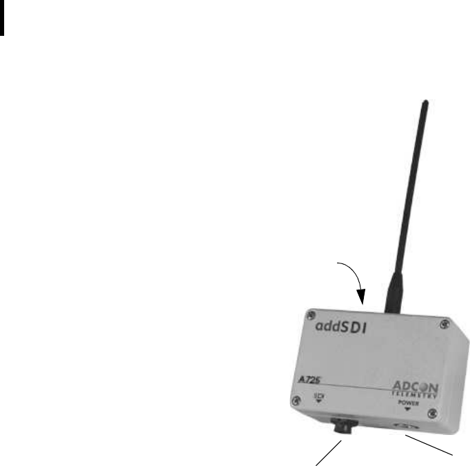
Figure 1 shows the front view of an addSDI RTU.
Figure 1. addSDI RTU
WARNING Do not turn or manipulate the Gore Prevent element!
The unit’s IP65 environmental protection may be affected.
Installing the RTU
The following restrictions apply:
• In general the typical “line-of sight” distance over which the
RTU can communicate is 1 km (.6 miles). This is valid if both
the RTU and its partner device are mounted on a 3 m mast (9
ft.); the results may vary under different conditions, and you
can sometimes achieve greater distances, sometimes shorter.
SDI-12
Connector
To
Solar
Panel
Gore PreventTM
CHAPTER 2
Installing the RTU
7
• As with all wireless communication devices, the higher the
transmitter is installed, the better the communication will be.
Field Installation
Installing addSDI RTUs in the field is a fairly simple process. You
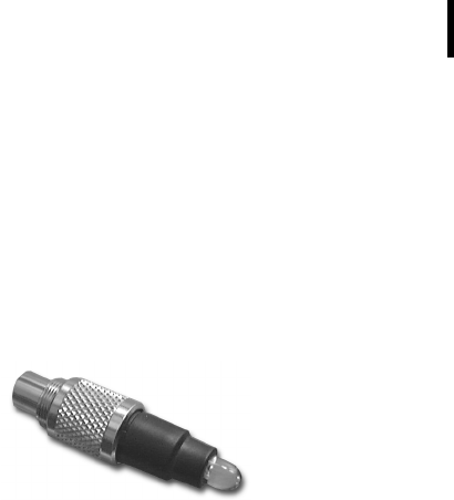
can perform a connectivity check with a LED tool. The LED tool is
shown in Figure 2.
Figure 2. LED Tool
Note: The LED tool is a blind plug to be connected to the POWER
connector.
Follow these steps to install an addSDI RTU in the field:
1. Review the installation area and choose the best site.
2. Perform a connectivity check using the LED tool:
a. Insert the LED tool into the POWER connector and wait
up to 10 seconds. If the unit connects to at least one
station (or a base station), it will light up the LED for
about 4 seconds.
b. Keep observing the LED tool and, after another several
seconds, the LED will blink one or more times (the
number of blinks indicates the number of stations it has
contacted).
3. Assemble the mast from the set of poles.
4. Drive the tipped aluminum pole vertically into the ground,
using a sledge hammer. Put the “pole pounder” cap on top
of the pole to protect it from damage while hammering it in.
How far you drive the pole into the ground depends on your
application and the soil. Sandy soils in windy areas might
require guy wires to secure the pole.
5. Using a pipe clamp, fasten the solar panel onto the aluminum
mast. Make sure that the panel is facing south (north if you are
located in the southern hemisphere) and is out of the way of
the addSDI RTU.

CHAPTER 2
Using the addSDI
8
Note: The solar panel can be mounted under or behind the
addSDI RTU, but be sure that the RTU does not shadow the
panel.
6. Fasten the addSDI RTU to the top of the mast using another
pipe clamp. Adcon recommends that you perform another
connectivity test, if you can, to check the positioning of the
device.
WARNING If you turn the fastening screws too tight, you might
damage the plugs.
7. Attach the SDI-12 sensor to the SDI jack and the solar panel to
the POWER jack by turning the connectors fastening screws
clockwise until secured tightly.
8. Secure access cable of the SDI-12 cable to the pole with cable
ties. To protect it from damage don’t let it sit on the ground!
This completes the installation of your addSDI RTU. If the SDI-12
jack is left unused, use the attached cap, meant to protect it
against moisture and dust. Be sure to make a note of the following
information because you’ll need it when you configure the device
in the software:
• Serial number of each RTU
• Type and address of SDI-12 sensors connected to each RTU
WARNING The SDI-12 sensor addresses must be set prior to
attaching the sensors to the SDI-12 bus. Be sure to use unique
addresses only! There is no way to resolve address conflicts once
the sensors are attached to the SDI-12 bus.
More about the LED tool
The LED tool allows you to rapidly check the status of an addSDI
RTU. After you insert the LED tool into the POWER connector, the
unit waits for up to two seconds and then sends a broadcast frame.
If a nearby station or receiver decodes the frame, it will answer—
this may take up to 10 seconds. When an answer is received, the
LED tool lights up for about 4 seconds. A few seconds later, the
LED will light up again one or several times - once per station/
receiver that answered to its broadcast frame.
After that the LED continuously blinks briefly in 0.5 second inter-
vals to indicate that the unit is alive and that the internal battery
has enough energy to operate. If the blinking interval lengthens to
2 seconds, the battery has become undercharged (that is, under

CHAPTER 2
Maintaining and servicing the RTU
9
5.6 volts but over 5.2 volts)—this is called the
misery
state. In this
state, an addSDI RTU reduces its activities to a minimum. The
radio unit is switched off, the sensor sampling ceases, and no data
is stored in the internal memory. Only the internal real-time clock is
maintained and the power management functions are performed.
If the battery level drops below 5.2 volts, the system switches off
completely, effectively decoupling itself from the battery in order
to protect it. In this case the LED tool stays permanently off. An
addSDI RTU in such a situation will restart only after connecting it
to an external power supply (even a solar panel under low light
conditions).
Note: New addSDI RTUs are delivered with their internal batteries
unformatted, meaning they are completely discharged, and
you should install them only on sunny days. The battery will
be fully charged after two consecutive sunny days, but you
should get an LED light-up after several minutes of charging
in the sunlight.
Configuring an addSDI RTU in the addVANTAGE software
To configure the addSDI RTU with an A840 Telemetry Gateway
and the addVANTAGE Pro software, check the
Base Station,
Telemetry Gateway A840 and Wireless Modem A440 User Guide
.
Maintaining and servicing the RTU
The A725 unit needs virtually no maintenance. It is waterproof and
designed to withstand harsh environmental conditions (-30 to
+70 °C, or -22 to 158 °F), high RH values, water, and other noncor-
rosive liquids. It conforms to the European protection class IP65.
This applies also to the connectors, as long as they are mated.
Don’t let unmated connectors on either the addSDI RTU or the
sensors be exposed to the environment for extended periods of
time.
The RTU battery
The internal NiMH rechargeable battery pack supplies 6.2 volts.
The internal electronics manage the battery charging/discharging
process, ensuring it a long life. This approach, coupled with a
remarkably low average consumption, allows an addSDI RTU to

CHAPTER 2
Using the addSDI
10
operate at least two weeks on a fully charged battery under the fol-
lowing conditions:
• The channel has moderate radio activity, with requests every
15 minutes.
• Sensor readings are stored in the internal memory every 15
minutes.
• The sensors do not drain excessive current (neither in sleep-
mode nor during measurement).
Table 1 shows the addSDI devices’ expected operating time on a
fully charged battery under various conditions..
Note: Radio activity means that one base station and between one
and three RTUs are active on the same operating frequency
as the addSDI remote station under test.
However, if for some reason (wear-out or accident) the battery
loses its capacity (noted in the software with repeated “Battery
low” messages), it must be replaced. Make sure, though, that the
problem is really due to the battery and not to a defective or dirty
solar panel.
Adcon highly recommends you to take good care of your solar
panels! Clean them frequently with a damp cloth. Rain droplets
might splash thin layers of soil onto the panels, wind and spraying
covers them with dust, birds tend to drop “things” onto them, thus
reducing their power output. Watch out for the surrounding vege-
tation! A solar panel, well exposed to the sun at the beginning of
the season, might be shadowed by growing vegetation as the sea-
son progresses.
Table 1. addSDI Device Operation Time
Radio
Activity
Average SDI-12
Sensor Current
Average
Consumption
(mA)
Estimated
Operation
(days)
No none 0.667 100
Yes none 0.833 80
Yes 1.1mA 1.8 37
CHAPTER 2
Maintaining and servicing the RTU
11
Changing the battery
If you have verified that the battery needs to be replaced, follow
these steps to do so:
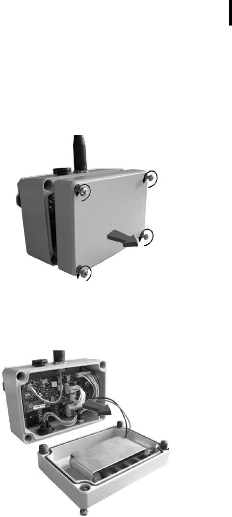
1. Open the lid by unscrewing the four screws in the corners of
the addSDI RTU, then remove the lid as shown in Figure 3.
Figure 3. Removing the addSDI Lid
2. The battery pack is connected to the electronics board by
means of a PCB connector. Remove the battery pack’s plug
from the PCB connector, as shown in Figure 4.
Figure 4. Unplugging the PCB Connector

CHAPTER 2
Using the addSDI
12
3. Unscrew the two screws of the metal cover that holds the
battery pack in place, then remove the cover. Figure 5 shows
the A725 battery pack inside the RTU.
Figure 5. A725 Battery Pack
4. Remove the battery pack and replace it with a new one
(obtainable from your Adcon dealer).
5. Put the metal cover back in place and secure it with the two
screws.
6. Replace the old cover seal with the new one, provided
together with your battery, as rubber gaskets tend to stiffen
and might not reseal properly. Place the rounded side of the
gasket into the groove and have the flat side showing!
7. Insert the battery plug into the PCB connector.
8. Mount the lid back, taking care that the rubber gasket sealing
the box is not out of place.
WARNING Be sure to mount the rubber gasket properly, so that
the unit’s IP65 environmental protection is not affected. Don’t
clamp the battery cable between the lid and the case, as this might
damage the cable and shorten the unit. Watch for soil and dust on
the seal, as this might lead to water ingress!

13
Chapter 3. Performing Advanced
Functions
With the appropriate knowledge you can configure the addSDI
devices in the field by using a hyperterminal window. To configure
the RTU you need a special serial adapter cable (item 200.720.540;
not included with the RTU; available from your Adcon distributor).
CAUTION Do not try to configure your addSDI devices if you are
not well familiar with the SDI-12 commands and bus architecture
—the unit may not communicate properly with the SDI-12 sensors
and/or with the remote measuring station or function with the
addVANTAGE software.
WARNING Tampering with parameters for the addSDI devices
may void your warranty or damage the device. In general, the
commands described in this chapter are intended for technical
support staff and users with a great deal of experience in handling
advanced hard- and software.
In the system architecture, the base station and RTU are both con-
sidered to be nodes. The base station is called the master node, or
master
, while the RTU is called the slave node, or
slave
.
CHAPTER 3
Performing Advanced Functions
14
Understanding connectors
The addSDI devices have cable attachments called connectors.
The connector type determines how the device communicates
with the sensors or the computer.
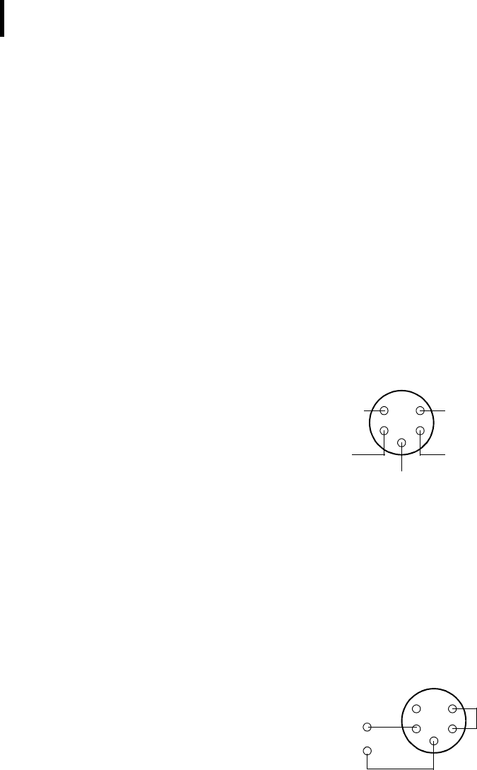
The POWER Connector
The RTU’s POWER connector, a 5-pin M9 jack, allows for:
• External charge supply (either a solar panel or an AC adapter)
if the internal rechargeable battery is used. (as in most cases).
• External power supply (battery or any DC source from 5.6 to
10 volts), with the internal battery removed
• Communication over a serial connection with 19200 baud
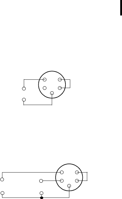
Figure 6 illustrates the connections available at the POWER con-
nector.
Figure 6. A725 POWER Connector (Top View)
WARNING The serial line is 3-volt CMOS compatible; therefore,
the above mentioned adapter cable must be used to reach the RS-
232 levels (Adcon item number 200.720.540).
You might want to use the POWER connector with something
other than the standard configuration. For example, if you want to
connect an external battery to the RTU, disconnect the internal
battery and use the configuration shown in Figure 7.
Figure 7. A725 Wiring up an External Battery
RxD
TxD
Ground
Battery
1
2
3
4
5
Ext Power
1
2
3
4
5
Battery
(5.6 to 10 Volt) -
Short
+
CHAPTER 3
Understanding connectors
15
If you want to use the internal battery with a different power sup-
ply (charger) than the ones provided by Adcon (120 or 300mA
solar panels or the ACS110 charger), make sure to use the wiring
as shown in Figure 8.
Figure 8. A725 Connection with External Power Supply
And if you want to use an external battery, charged by its own
solar panel, you need to disconnect the internal the internal bat-
tery and the Adcon solar panel and use the wiring as shown in
Figure 9.
Figure 9. A725 Connection with External Battery and Power Supply
The SDI Connector
The SDI connector is used to connect the addSWITCH A725 to an
SDI-12 Sensor bus (See Figure 10). The connector used is a female
5 pin SWITCHCRAFT jack (EN3P5F, the counterpart is the
EN3C5M).
The A725 comes with a 1m cable with flying ends. A standard
cable clamp can be used to connect the sensors. It is up to the
user to protect this cable clamp for outdoor usage. Please contact
your local Adcon dealer for special SDI-12 wiring boxes.
1
2
3
4
5
Charger
(9 to 10 Volt,
+
-
Short
100 to 300 mA)
+
1
2
3
4
5
Charger
(must fit the
+
-
Short
Battery
(5.6 to 10 Volt)
Battery) -

CHAPTER 3
Performing Advanced Functions
16
Figure 10. The SDI-12 Connector
If you do not use an SDI-12 sensor with the proper cable already
mounted, but will connect it to the SDI bus through a wiring box, it
is absolutely crucial to obey the following instructions: first identify
the function of each of the sensors cables. Then connect them to
the wiring box in exactly the folloing order: First connect SDI-GND.
Then connect SDI-POWER (only if a sensor receives its power sup-
ply from the RTU) and last connect SDI-DATA. Else you might
cause the SDI-12 bus to perform unexpectedly!
CAUTION Some SDI-12 sensors have a rather high startup current,
which prevents operation with our low power addSDI RTU. Always
check your SDI-12 sensor’s peak current draw upon start-up! This is
of particular importance when connecting more than one sensor to
the SDI-12 bus - while one sensor might still operate flawlessly with
your RTU, two might draw too much current and cause the RTU to
shut off the bus. This will occurr when the total power draw on the
SDI-12 bus goes beyond 500mA. In case of doubt or questions
please consult your sensor supplier or your Adcon dealer.
Note: Please see also SDI-12 spec for additional wiring and setup
information.
To enable the SDI-12 bus operation, a jumper must be installed
between GND (Pin 1) and SDI-Sense (Pin 2). This jumper is factory
installed in the connector of the standard 1m cable, which comes
with your addSDI RTU.
Note: When the SDI-12 bus is not used, please disconnect the SDI
connector and the solar panel from your addSDI. The RTU
will then switch to a power save mode.
1
2SDI−DATA
SDI−GND
34
5
SDI−Sense
SDI−POWER
green
yellow
GND
gray
CHAPTER 3
SDI-12 Sensor Connections
17
SDI-12 Sensor Connections
Sensor powered by RTU
To connect a single SDI-12 sensor, that does not have it’s own
power supply, follow the wiring scheme as shown in Figure 11.
Figure 11. Single Sensor Connection, sensor is powered by the RTU
Note: In this configuration, the RTU powers the SDI-12 sensor. The
sensor must be capable of working with a supply voltage as
low as 5.6V.
WARNING Check the minimum supply voltage of your sensor
BEFORE
installing it! This information should be available from
your sensor supplier.
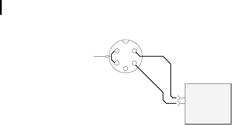
Self powered Sensor
Sensors with an integrated power supply must be connected fol-
lowing the wiring scheme in Figure 12.
Jumper
Detection
SDI−DATA
SDI−GND
POWER
SDI−12 SENSOR
1
2SDI−DATA
SDI−GND
34
5
SDI−Sense
SDI−POWER
GND
gray
yellow
green
CHAPTER 3
Performing Advanced Functions
18
Figure 12. Single Sensor Connection, for sensor with internal battery
pack
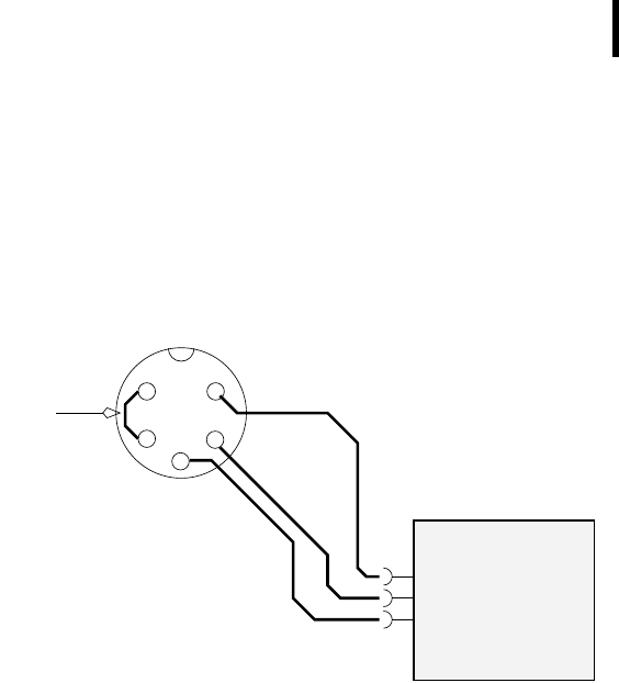
Multiple Sensors connected to the SDI-12 bus
Multiple sensors can be connected to the SDI-12 bus as long as
the following conditions are met:
• the maximum
total (!)
current consumption (500mA) is not
exceeded
• the maximum number of sensor values (20) is not exceeded
• all sensors have unique addresses
WARNING If two sensors with identical addresses are connected
to the same bus, communication with these sensors is not possible.
Note: The factory default address of most SDI-12 sensors is usually
0. Please use an appropriate tool, usually delivered by the
sensor manufacturer, to change the address. The A725
addSDI RTU is not capable of changing addresses of SDI-12
sensors.
The sensors can be connected in a star, daisy chain or mixed topol-
ogy. Self powered and RTU powered sensors can also be mixed.
See Figure 13 for details.
Jumper
Detection
SDI−DATA
SDI−GND
1
2SDI−DATA
SDI−GND
34
5
SDI−Sense
SDI−POWER
GND
gray
yellow
green
self powered
SDI−12 SENSOR

CHAPTER 3
Communicating with the RTU
19
Figure 13. Multiple SDI-12 sensors
Communicating with the RTU
WARNING Please disconnect the SDI connector, when
attempting to configure the A725 RTU via the A720SC serial cable.
You will not be able to communicate with your A725 addSDI RTU
as long as the SDI connector is plugged in.
You can use a Windows Hyperterminal window to connect to the
addSDI RTU. After you have installed the system, follow these
steps to configure the device and set the default parameters:
Note: To configure the A725 RTU you must use the A720SC
adapter cable mentioned above (available from your Adcon
dealer) and connect it to the POWER jack of the RTU.
1. Open a Hyperterminal window.
2. Select the appropriate serial port and click OK.
3. Configure your terminal as follows:
• 19200 baud
• 1 stop bit
• 8 data bits
• No parity
• No protocol (neither hardware nor software)
SDI−DATA
SDI−GND
self powered
SDI−12 SENSOR
Jumper
Detection 1
2SDI−DATA
SDI−GND
34
5
SDI−Sense
SDI−POWER
GND
gray
yellow
SDI−DATA
SDI−GND
SDI−12 SENSOR
POWER
green

CHAPTER 3
Performing Advanced Functions
20
4. Select OK to open the terminal window.
5. Press Enter to generate a response in the window.
Serial communication protocol
This protocol is based on a master sending commands and a node
answering. The whole communication is conducted in plain ASCII
strings. When exchanging numbers, they are represented in deci-
mal format. All commands are terminated with a CR/LF combina-
tion. All responses (answers) are terminated with the # character.
General format of a command
The commands have the following format:
ID Command Param1 Param2 ... ParamN
•ID is the destination device. If you include an ID as part of a
command, the node checks whether ID=ownID. If it does, the
node executes the command on itself. If the ID is not the
node’s ID, the node executes the command on a remote
device, if such an ID exists. Not naming any ID implies that the
command is addressed locally.
Note: Not all the commands can be executed remotely!
•Command is the command proper, which can be composed of
a variable string of characters (for example, SLOT). Each node
can implement a set of commands depending on the
functionality of the node itself. However, as a minimum
requirement, a node recognizes the CMDS command, which
returns a list with the commands accepted by the node.
•Param1 Param2 ... ParamN represent the parameters,
which are command dependent. If you type no parameters
when you issue a command, it is the equivalent of querying
for information (the GET version of a command). If you type
parameters, you are issuing the SET version of a command
and are setting the command to the parameters you typed.
General format of an answer
The answers have the following format:
ID Command Result1 Result2 ... ResultN ErrResult
#

CHAPTER 3
Using terminal commands
21
•ID is the answering device. If a command was further routed,
it is the ID of the end device. The answer must always contain
the ID on return.
•Command is the string representing the original command. It
is supplied so that a master can distinguish between the
answers it is waiting for, and out-of-band notifications (which
may come, for example, over the radio port of a node). As
with the ID, the command name must always be supplied.
•Result1 Result2 ... ResultN are the result values
returned by the remote node. If the ErrResult is not zero,
all other possible characters and/or strings until the end of
the line may be ignored.
•ErrResult shows whether the command was successfully
executed or not. If this value is 0, the command was
successfully executed. If this value is other than 0, the
command failed. The number may further indicate the error
type. (See also “Returned errors list” on page 37.)
The answer string may contain any number of spaces or CR/LF
characters between its components; however, after the terminator
(#) no other characters are allowed.
Using terminal commands
The A725 addSDI firmware is basically the same as used with the
A723 addIT, except for the following items:
• new device type: A725
• only SDI-12 Sensors available
The following list describes all available commands and their
usage.
Note: You can type uppercase or lowercase characters because
the commands are not case sensitive.
CMDS
DESCRIPTION Returns a list of supported commands.
PARAMETERS None.
RETURNS A list of strings separated by spaces.
REMARKS GET only.

CHAPTER 3
Performing Advanced Functions
22
REMOTE No.
EXAMPLE CMDS
15535 CMDS CMDS ID PMP RSSI TIME FREQ SLOT DATA
INFO RX TX FDEV 0
#
TIME
DESCRIPTION Sets/returns the real time clock.
PARAMETERS The actual time, or none in the GET version.
RETURNS The actual time as dd/mm/yyyy hh:mm:ss.
REMARKS GET/SET.
REMOTE No.
EXAMPLE TIME 12/12/1999 22:10:10
15535 TIME 0
#
TIME
15535 TIME 12/12/1998 22:10:10 0
#
FREQ
CAUTION Do not change the frequency of your device without
reason: apart from the fact that it might not communicate in the
network anymore, you might also violate the applicable
radiocommunications laws in your country. Depending on the
destination country, some models may also return an error
message.
DESCRIPTION Sets/returns the operating frequency.
PARAMETERS The operating frequency and step (Hz), or none in the GET version.
RETURNS The actual frequency and step, in Hz.
REMARKS GET/SET.
REMOTE Yes, SET only.
EXAMPLE FREQ 433925000 25000
15535 FREQ 0
#

CHAPTER 3
Using terminal commands
23
FREQ
15535 FREQ 433925000 25000 0
#
RSSI
DESCRIPTION Sets/returns the Relative Signal Strength Indicator threshold at
which the RF receiver must wake up.
PARAMETERS The threshold value. For the A725, it can take values from 0 to
255; it is typically factory set to 42.
RETURNS The instant RSSI value and the programmed threshold.
REMARKS GET/SET.
REMOTE No.
EXAMPLE RSSI 50
15535 RSSI 0
#
RSSI
15535 RSSI 34 50 0
#
Note: The values of the RSSI threshold have no units, they are arbi-
trary. However, a value of 160 corresponds approximately to
the maximum value allowed in the addVANTAGE software
(that is, 8 µV).
ID
DESCRIPTION Sets/returns the node’s ID.
PARAMETERS The node ID.
RETURNS The node ID.
REMARKS GET/SET.
REMOTE Yes, SET only.
EXAMPLE ID 4557
15535 ID 0
#

CHAPTER 3
Performing Advanced Functions
24
ID
4557 ID 4557 0
#
SLOT
CAUTION Changing these parameters may adversely affect the
ability of the device to operate for extended periods under low sun
shine conditions.
DESCRIPTION Sets/returns the node’s sampling interval and rate.
PARAMETERS The interval (60 - 65535) and rate (0 - 255). The interval represents
the time (in seconds) elapsed between two slots stored in the inter-
nal memory, while the rate represents the numbers of samples
used to build the average that will be stored.
Note: The rate parameter is not relevant for the A725 RTU. The
sensors’ firmware is responsible for calculations of avaraged
values etc.
RETURNS The interval and rate.
REMARKS GET/SET. The default interval is 900 (15 minutes) and rate is 15 (15
samples per 15 minutes).
REMOTE Yes, SET only.
EXAMPLE SLOT 900 15
15535 SLOT 0
#
SLOT
15535 SLOT 900 15 0
#
PMP
DESCRIPTION Sets/returns the node’s Power Management Parameters (switches
the battery charge on/off).
PARAMETERS The lower (switch on) and the higher limit (switch off), both in volts
x 10. Standard Values are 65 (for 6.5 Volts) for switch on and 72 (for
7.2 Volts) for switch off (for a standard 6.2 Volt NiCd or NiMH bat-
tery). From these values, other thresholds are internally computed.
RETURNS The lower (switch on) and the higher limit (switch off), both in volts
x 10.

CHAPTER 3
Using terminal commands
25
REMARKS GET/SET.
REMOTE Yes, SET only.
EXAMPLE PMP 65 72
15535 PMP 0
#
PMP
15535 PMP 65 72 0
#
DATA
DESCRIPTION Returns data stored for a certain device.
Note: This command cannot be used to retrieve data from the
SDI-12 subsystem. Please see the description of the SDI-
DATA command therefore.
PARAMETER The ID of the device for which the data is requested and the date/
time (in the standard format) the data was stored. If missing, then it
refers to the data of the local device.
RETURNS A data block.
Note: The addSDI does not support analog sensors.
REMARKS GET only. If the date/time parameter is not included, the latest
data is returned. If the date/time parameter is included, the data
closest to, but later than, the given date/time is returned.
REMOTE Yes, for a GET, but only one frame at a time. The A725 can issue
the command only for itself, locally.
EXAMPLE DATA 15535 1/3/2000 12:12:12
15535 DATA b1 b2 b3 ... bn 0
#
The data block returned will typically contain a number of data
frames (telegrams). The structure of a block is as follows:
dd mm yyyy hh mm ss si ft d1 d2 ... dn dd mm yyyy ... dn cs
where:
•dd mm yyyy is the date
•hh mm ss is the time

CHAPTER 3
Performing Advanced Functions
26
•si is the size of the frame
•ft is the frame type (39 for the A725)
•d1 d2 ... dn are the data values (the frame content)
•cs is a 16-bit checksum obtained by summing the bytes and
discarding the carries over 0xFFFF
The A725 devices always responds with a type 39 data frame. The
composition of the data block of such a frame (the values marked
as d1, d2... dn) is depicted in Figure 14, while the digibyte is
depicted in Figure 15.
Figure 14. Frame 39 description
Figure 15. The Digibyte
The remote version is limited to a single frame. An example of such
a command is given below:
9999 DATA 9999 13/12/2006 19:46:00
9999 DATA
13 12 2006 19 46 23 13 39 255 255 3 0 0 89 0 0 0 0
0 0 0 0 0 0 0 0 2258 0
#
RF incoming
RF outgoing
Digibyte
Pulse Counter CNT0, always 0
Pulse Counter CNT1, always 0
I/O A Cabling 2, always 0
I/O A Cabling 3, always 0
I/O B Cabling 1, always 0
I/O B Cabling 2, aways 0
I/O B Cabling 3, always 0
Battery
I/O A Cabling 1, always 0
Checksum
b7 b0
SC Res Res Res Res Res Res Res
SC — Solar Cell (0–off, 1–on)

CHAPTER 3
Using terminal commands
27
Notice that if you need to get data that is not the last (newest) slot
remotely from a device, the ID must be supplied twice. If you need
to get the last slot stored, you can ignore the ID and the date/time
parameters:
9999 DATA
9999 DATA
13 12 2006 22 15 00 13 39 255 255 3 0 0 87 0 0 0 0
0 0 0 0 0 0 0 0 3311 0
#
IMME
DESCRIPTION Samples all inputs and immediately returns the sampled data.
Note: This command cannot be used to get data values from the
SDI-12 subsystem.
PARAMETER The ID of the requested subsystem; default is the standard A/D
subsystem of the A725 (ID=0).
RETURNS A data block (see also “DATA” on page 25).
Note: The analog inputs are disabled on the A725.
REMARKS GET only. The command needs a certain delay to execute (for
example, for the standard subsystem this delay amounts to two
seconds. The delay is necessary to allow for the sensors to settle
after applying power to them.
REMOTE No.
EXAMPLE IMME
4711 imme 13 12 2006 20 00 18 13 39 0 0 127
0 0 84
0 0 0 0 0 0
2209 0
#
FDEV
DESCRIPTION Formats the internal memory (destroys all the data).
PARAMETER If the parameters are missing, the command will destroy all the
data in the EEPROM file. If a parameter is given, the EEPROM type
is defined (data won’t be destroyed). The following EEPROM types
are currently defined:

CHAPTER 3
Performing Advanced Functions
28
• 0 – 16 Kbytes (e.g. model 25128)
• 1 – 32 Kbytes (e.g. model 25256)
RETURNS Nothing.
REMARKS SET only.
REMOTE Yes, SET only.
EXAMPLE FDEV 1
15535 FDEV 0
#
INFO
DESCRIPTION Returns various status information.
PARAMETER None.
RETURNS A list of a device’s internal variables:
ID INFO rf_in rf_out date time ver clk stack cop batt temp
days_uptime hr:min_uptime rssi pmp_low pmp_high type slot sam-
ples po err_level
#
The formats for the above parameters are as follows:
•rf_in and rf_out as a decimal
•date as dd/mm/yyyy
•time as hh:mm:ss
•ver as x.x
•clk, stack, and cop as decimal; they represent internal
housekeeping parameters: the A725 uses cop to number
watchdog occurrences, but clk and stack are currently
undefined
•batt as battery level using the standard voltage conversion
equation (0 is 0 volts, 255 is 20 volts)
•temp as internal temperature in the A725 housing, which is
device dependent. The precision of the sensing element is
low (±2°C), but it is sufficient for battery power management

CHAPTER 3
Using terminal commands
29
(charge/discharge). To compute the actual value (in °C), the
following equation must be used:
•days_uptime in days; together with hr:min_uptime, it
represents the amount of time the device is up without a reset
or watchdog
•hr:min_uptime in hours:minutes format
•rssi as decimal; it is the value programmed with the RSSI
command
•pmp_low and pmp_high are the programmed values with
the PMP command )
•type is used to represent the device type; the following
types are currently assigned:
— 0 for A730MD
— 1 for A720
— 2 for A730SD
— 3 for A720B
— 4 for A733
— 5 for A723
— 6 for A440
— 7 for A733GSM
— 8 for A731
— 9 for A732
— 10 for A740
— 11 for A740GSM
— 12 for A724
— 13 for A725
— 14 for A726
slot and samples are the actual values programmed by
means of the SLOT command
•po is the power output of the device during the last frame
sent
•err_level is the error value; 0 means no error
REMARKS GET only.
REMOTE Yes, GET only. The A725 can issue the command both remotely
and locally.
Temp °C[ ] internalTemp 400⋅
255
------------------------------------------------- 68–=

CHAPTER 3
Performing Advanced Functions
30
EXAMPLE INFO
15535 INFO 0 84 13/12/2006 20:02:29 2.10 2 0 0 85
59 0 3:52 42 65 72 12 60 1 0
#
RX
DESCRIPTION Switches the unit to permanent receive mode (for tuning pur-
poses).
PARAMETERS None.
RETURNS Nothing.
REMARKS The system stops, and exits the command only when a key is
pressed. This command returns no message.
REMOTE No.
EXAMPLE RX
15535 RX 0
#
TX
DESCRIPTION Switches the unit to transmit mode (for tuning purposes).
PARAMETERS None (sends an unmodulated carrier), 1 (sends a 1 kHz modulated
carrier), 0 (sends a 2 kHz modulated carrier) or 5 (sends a mixed 1
+ 2 kHz modulated carrier).
RETURNS Nothing.
REMARKS The system stops, and exits the command only when a key is
pressed. This command returns no message.
REMOTE No.
EXAMPLE TX
15535 TX 0
#
TX 1
15535 TX 0
#

CHAPTER 3
Using terminal commands
31
TX 5
15535 TX 0
#
B
DESCRIPTION Sends a broadcast frame.
PARAMETERS None.
RETURNS A data block.
REMARKS After the device has sent the broadcast frame, it will listen for
answers. All valid answers will be listed with their IDs.
REMOTE Yes. A device getting this frame would have to wait for a random
time (2 to 10 seconds) before performing the actual broadcast; if
no terminal is active, then no results will be listed. A list of heard
stations with their RF levels will be updated in the memory and will
be available whenever the BLST command is issued.
EXAMPLE B
15535 B 0
#234 BA 0
#7851 BA 0
BLST
DESCRIPTION Lists the stations heard after the last broadcast command was
issued.
PARAMETERS None.
RETURNS The date and time when the broadcast was performed, the num-
ber of stations heard, and a list with the heard stations’ ID and their
respective RF levels.
REMARKS GET only.
REMOTE Yes. The remote version will list only the first 9 stations heard.
EXAMPLE BLST
15535 BLST 10/12/1999 12:15:04 4
2008 150
2003 177
6883 168
4027 220
#

CHAPTER 3
Performing Advanced Functions
32
VER
DESCRIPTION Requests the firmware version of the device.
PARAMETERS None.
RETURNS The current version.
REMARKS GET only.
REMOTE No.
EXAMPLE VER
15535 VER 2.14.0 0
#
SDI
DESCRIPTION A complex command that can be used to check the status of the
SDI-12 subsystem, as well as configure it.
PARAMETERS The command has a multitude of options. If issued without param-
eters, the GET variant is implied, i.e. the status of the SDI-12 sub-
system will be returned (see also bellow). The following
parameters/formats of the command can be used:
•sdi + adds a measurement to the list. If you add the C
argument, CRC-measurements are used (default is without
CRC). You can set a different measurement method with M
followed by a number (default M0) or you can choose
continuous measurement by choosing R followed by a
number. In addition, you can set up to 24 bits in the value
index map by adding a mix of several index numbers
(separated by white spaces or ',', default 0-19) and bit masks
starting with 0x, e.g., 0x3 for indexes 0 and 1 (see also the
examples). The R-Method performs “Continuous
Measurements” (see SDI-12 standard). All measurements are
performed sequentially in the order they are situated in the
table.
•
sdi -
removes a configuration entry. The argument are the
sdi-
addr
and the
method
('M' or 'R') and optionally the checksum
flag 'C'. Sensors are considered as belonging to the same
sensor unit if they have the same
sdi-addr
and
method
.
•
sdi I
returns the sensor configuration, including the sensor
identifier string in double quotes, where '\' and '"' in the id
string are escaped with a '\'. Invalid characters (those outside

CHAPTER 3
Using terminal commands
33
the SDI-12 allowable characters 0..31, 127..255) are
substituted with an underscore (_). The arguments are the
same as in
sdi -
command.
•
sdi !
resets the SDI-12 configuration. All previous entries are
deleted from the configuration table.
•
sdi *
forces a sensor discovery cycle after the next
measurement cycle. The status of the operation can be
checked by issuing an sdi command without arguments (the
GET version). All sensors discovered will be displayed in the
list. When the discovery operation ends, “D” flag changes
back to “d” (see also below).
CAUTION Use the sdi ! and sdi * command with absolute
precaution, because the RTU’s SDI-12 configuration may be
deleted!
RETURNS The following information is supplied in the form of a string of
characters in the case the command was issued without arguments
(the GET variant):
•
a/A —
The presence of the SDI-12 BUS:
a
absent,
A
active;
•
w/W —
Wait-State of the system:
w
not waiting,
W
waiting for
an SDI-12 sensor;
•
m/M —
Measurement command status:
m
no measurement is
being done,
M
a measurement is in progress;
•
v/V —
Availability of Values for storage:
v
no values are
available,
V
values are available for local storage;
•
d/D —
discovery initiation:
d
no discovery pending,
D
discovery pending (will be done at the next sensor poll cycle).
In addition, for every programmed SDI-12 sensor, the following
information will be listed:
•
sensor id —
the sensor ID in ASCII (0 - 9, A - Z and a - z);
•
method + CRC —
the measuring method, either
M
(normal)
or
R
(continuous), optionally followed by the CRC flag (C);
•
index —
the indices used (in hexadecimal), e.g.:
0x3
if indices
0 and 1 are used.
Note: For further information about the significance of the above
terms please also consult the specification of the SDI-12
standard, version 1.3 (http://www.sdi-12.org).

CHAPTER 3
Performing Advanced Functions
34
REMARKS SET/GET.
REMOTE Yes.
EXAMPLE Initiate a “discovery“command
#sdi *
#sdi
35385 sdi awmvD 0 0
Discovery is pending (D).
Detach A720SC Serial Cable and attach SDI-12 bus and wait for at
least 1 minute; the bus will be scanned.
Detach the SDI-12 bus, wait 2s and attach A720SC again. Proceed
with the following command:
#sdi
35385 sdi awmvd 1 0 M0 0xfffff 0
#
The answer indicates: 1 sensor found at address 0, method 0 and
index mask is 0xfffff (all 20 indices, 0-19).
Note: Every “1” in the index mask (binary), corresponds to a
selected index, e.g. 0x3 corresponds to index 0 and 1.
Example for three equivalent configuration commands:
sdi + 0 M0 3,4,5,9
sdi + 0 M0 0x238
sdi + 0 M0 0x230,3
The binary representation of 0x238 is: 1000111000b (bits 3,4,5 and
9 are set).
DATASDI
DESCRIPTION Returns a slot of SDI-12 sensor data, if any.
PARAMETERS Offset and date/time, both optional. If an offset is specified, then
only the values after the offset are returned, all others are skipped.

CHAPTER 3
Using terminal commands
35
The date/time specifies the first slot to be retrieved that is strictly
“younger” than the specified time stamp.
RETURNS The data block returned will typically contain a number of data
frames. The structure of a block is as follows:
dd mm yyyy hh mm ss si ft rfin rfout db batt sdih
sdib1 sdib2 ... sdibn cs
where:
•
dd mm yyyy
is the date
•
hh mm ss
is the time
•
si
is the size of the frame (variable for the SDI frames)
•
ft
is the frame type (60)
•
rfin
is the RFin RSSI value
•
rfout
is the RFout RSSI value
•
db
is the digibyte value
•
batt
is the battery voltage value
•
sdih
ist the SDI-12 header
•
sdib1, sdib2 ... sdibn
are the SDI-12 sensor quadruples
•
cs
is a 16-bit checksum obtained by summing the bytes and
discarding the carries over 0xFFFF (float values are not
included in the checksum).
The composition of the data block of such a frame (the values
marked as sdih, sdib1... sdibn) is depicted in Figure 16.

CHAPTER 3
Performing Advanced Functions
36
Figure 16. SDI-12 Data Frame, part of type 60 Frame
The frame is similar to the standard DATA frame, but has the SDI
sensor values appended after the battery value. The frame type 60
contains SDI-12 data only.
SDI-12 specific parameters are explained below:
•
SDI count —
represents the number of configured SDI values
following in the SDI data block.
•
SDI offset —
the offset in the SDI-12 frame. Usually it is 0 (no
offset is used).
•
SDI available —
is the number of SDI-12 sensor values
effectively returned. The difference between the
SDI count
and
SDI available
indicates missing sensors (down or damaged).
Usually these two values are identical.
•SDI values — this is a number of SDI-12 quadruples:
• SDI address
• SDI method
• SDI index
• SDI value (floating point).
See also the example below .
Note: The remote version is limited to a single frame.
REMARKS GET only.
SDI count
SDI address
SDI method
SDI index
SDI value (floating point)
SDI address
SDI offset
SDI available
SDI method
SDI index
SDI value (floating point)
SDI value #1
SDI value #2...
SDI address
SDI method
SDI index
SDI value (floating point)
SDI value #n

CHAPTER 3
Returned errors list
37
REMOTE Yes.
EXAMPLE #12800 datasdi
12800 datasdi 16 5 2003 20 14 49 44 60 255 255 127
87 9 0 9 3 0 0 74.379401 3 0 1 68.117003 3 0 2
58.832397 3 0 3 51.611795 3 0 4 38.346400 3 0 5
19.800799 3 0 6 14.895999 3 0 7 3.553500 3 0 8
0.037200 2953 0
#
SDA
DESCRIPTION Sets/returns the maximum delay for waiting awake (i.e. out of
sleep mode) for a service request of an SDI-12 sensor. This param-
eter is set to 30 seconds by default. A larger value may lead to
higher power consumption. This should be used in cases an SDI-
12 sensor needs large time values to return a sensor result. If you
have such sensors and still want to use them, you need to change
this parameter, but please be aware of the fact that the RTU’s
power consumption will be higher.
PARAMETERS Maximum wake time in seconds (1 to 999).
RETURNS The current value (in seconds).
REMARKS SET/GET.
REMOTE No
EXAMPLE SDA
35385 SDA 30 0
#SDA 50
35385 SDA 0
#
Returned errors list
In the following section you find the error messages you might get.

CHAPTER 3
Performing Advanced Functions
38
Command line interpreter
• 1 — command not recognized (=it doesn’t exist or isn’t
supported)
• 2 — command line buffer overflow (input line too long)
• 3 — internal error
• 4 — reserved
• 5 — missing or false parameters in command
• 6 — operation not implemented
• 7 — remote operation not allowed
• 8 — Invalid IMEI checksum number
Device descriptors and storage handler
• 10 — device not found (attempt to perform a command on a
non-existent device)
• 11 — device already exists
• 12 — reserved
• 13 — no more space for descriptors (too many devices)
• 14 — no more records for the specified device
• 15 — temporary communication break, no more data (the last
request was not successful)
• 16 — time-out (the handler blocked or is busy)
• 17 — internal error
• 18 — attempt to insert a reserved device ID number (0 or
65535)
Real time clock
• 20 — incorrect time supplied (conversion to time_t was not
possible)
Radio interface
• 30 — error at receive (CRC, etc.)
• 31 — unexpected frame received
• 32 — wrong length
• 33 — reserved
• 34 — reserved
• 35 — time-out (remote device not responding)

CHAPTER 3
Returned errors list
39
• 36 — receiver busy (for example, just executing a polling
series)
• 37 — time stamp of a frame is too far in the future
• 38 — general modem error

39
Appendix. Specifications
The A725 addSWITCH was built to match the specification of the
ETSI 300 220, Class I, Subclasses a and b, but other national norms
are similar to this (for example, the CFR 47, Part 90, Subpart J).
Table 2 shows the main operational parameters of the A725.
Table 2. Operational Parameters
Parameter Min Typ Max Unit
Common
Supply 5.0 6.2 10.0 V
Operating Temperature -30 +70 °C
Relative Humidity 10 99 %
Class Protection IP65
Data Rate (using the onboard software modem) 1000 1500a2000 bps
Operating Frequency b432 470 MHz
Frequency Stability (-20 to +60 °C) ±1.5 kHz
Frequency Stability (-30 to +70 °C) ±2.5 kHz
Receiver

40
Sensitivity (10 db S/N) -105 dBm
Image Frequency Attenuation (1st IF = 45 MHz) 35 dB
Local Oscillator Leakage 2 nW
Adjacent Channel Attenuation 55 dB
RSSI Dynamic 90 dB
Operating Current (incl. onboard microcontroller)c20 mA
Transmitter (all measurements made on a 50 Ohm resistive
load)
Output Power 7 9 10 dBm
Spurious Radiation (0 to 862 MHz) 2 nW
Spurious Radiation (862 MHz to 3.5 GHz) 200 nW
Adjacent Channel Power (12.5 kHz version) -32 dBm
Adjacent Channel Power (25 kHz version) -44 dBm
Occupied Bandwidth (12.5 kHz version) 8.5 kHz
Occupied Bandwidth (25 kHz version) 15 kHz
Operating Current (incl. onboard microcontroller) 50 mA
SDI-12
Sensor Supply Voltaged5.5 6.0 10.0 V
Sensor Supply Currente500 mA
a. Data rate is content dependent.
b. This parameter represents the tuning range; the switching range may be limited in
the software to a narrower space (even to the extent of a single channel).
c. Continuous duty.
d. This applies for sensors which are powered by the RTU’s internal battery.
e. This is the maximum peak current for all sensors on the SDI-12 bus.
Table 2. Operational Parameters (Continued)
Parameter Min Typ Max Unit