Ott Hydromet Business Unit Adcon Telemetry A740-46 Telemetry transceiver User Manual 1
Adcon Telemetry GmbH Telemetry transceiver 1
UserManual.wiki
>
Ott Hydromet Business Unit Adcon Telemetry
>
A740 46 User Manual
User Manual
Navigation menu
Upload a User Manual
Namespaces
Wiki Guide
HTML
PDF
Info
Views
User Manual
Discussion / Help
Navigation


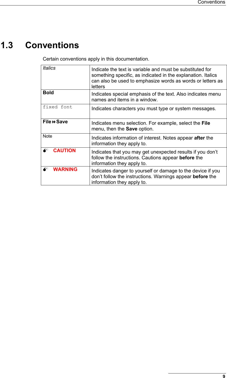

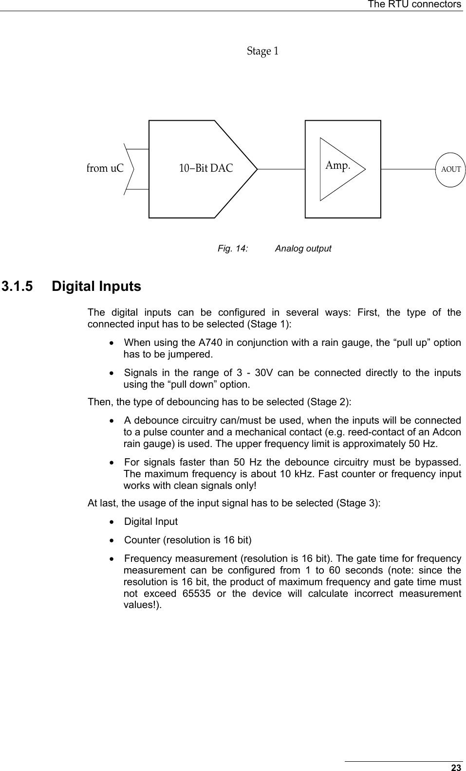
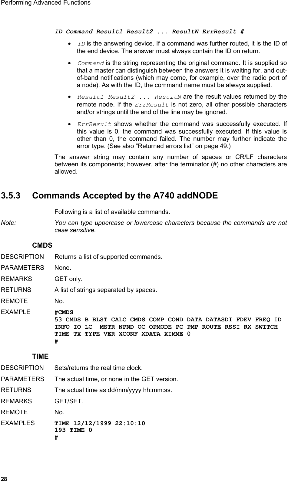
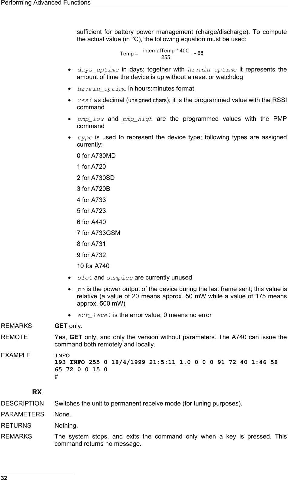
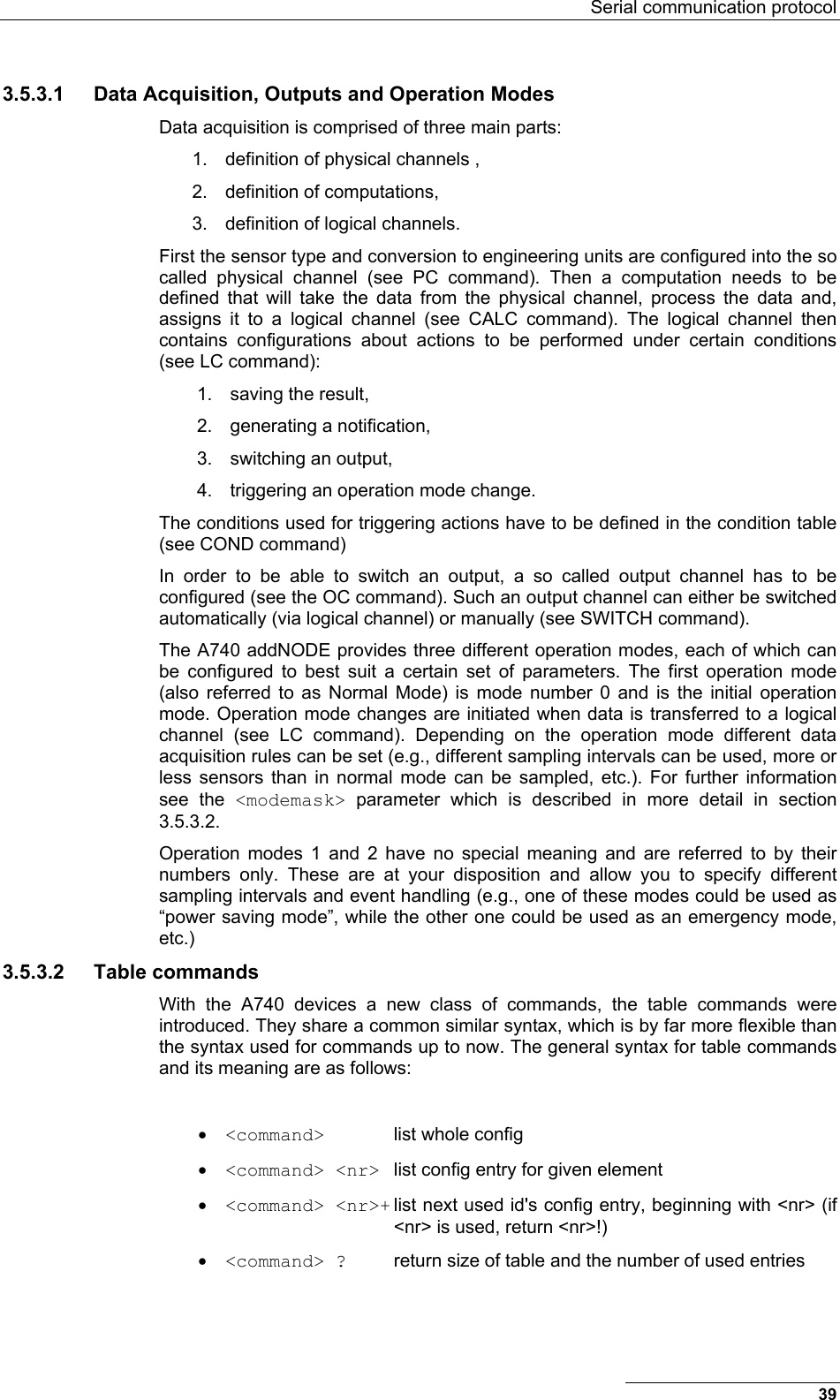
![Serial communication protocol Note: To configure the A740 RTU, you must have a special adapter cable (available from Adcon) and plug it into the POWER connector. 1. Open a HyperTerminal window. 2. Select the appropriate serial port and click OK. 3. Configure your terminal as follows: • 19200 baud • 1 stop bit • 8 data bits • No parity • No protocol (neither hardware nor software) 4. Select OK to open the terminal window. 5. Press Enter to generate a response in the window. 3.5 Serial communication protocol This protocol is based on a master sending commands and a node answering; the whole communication is conducted in plain ASCII, as strings. When exchanging numbers, they are represented in decimal format. All commands are terminated with a CR/LF combination. All responses (answers) are terminated with the # character. 3.5.1 General format of a command The commands have the following format: [ID] Command Param1 Param2 ... ParamN • ID (optional) is the destination device. If you include an ID as part of a command, the node checks whether ID=ownID. If it does, the node executes the command on itself. If the ID is not the node’s ID, the node executes the command on a remote device, if such an ID exists. If the ID is missing, this implies that the command is addressed locally. Note: Not all the commands can be relayed remotely. • Command is the command proper, which can be composed of a variable string of characters (for example, INFO). Each node can implement a set of commands depending on the functionality of the node itself. However, as a minimum requirement, a node recognizes the CMDS command, which returns a list with the commands recognized by the node. • Param1 Param2 ... ParamN represent the parameters, which are command dependent. If you type no parameters when you issue a command, it is the equivalent of querying for information (the GET version of a command). If you type parameters, you are issuing the SET version of a command and are setting the command to the parameters you typed. 3.5.2 General format of an answer The answers have the following format: 27](https://usermanual.wiki/Ott-Hydromet-Business-Unit-Adcon-Telemetry/A740-46/User-Guide-533367-Page-27.png)
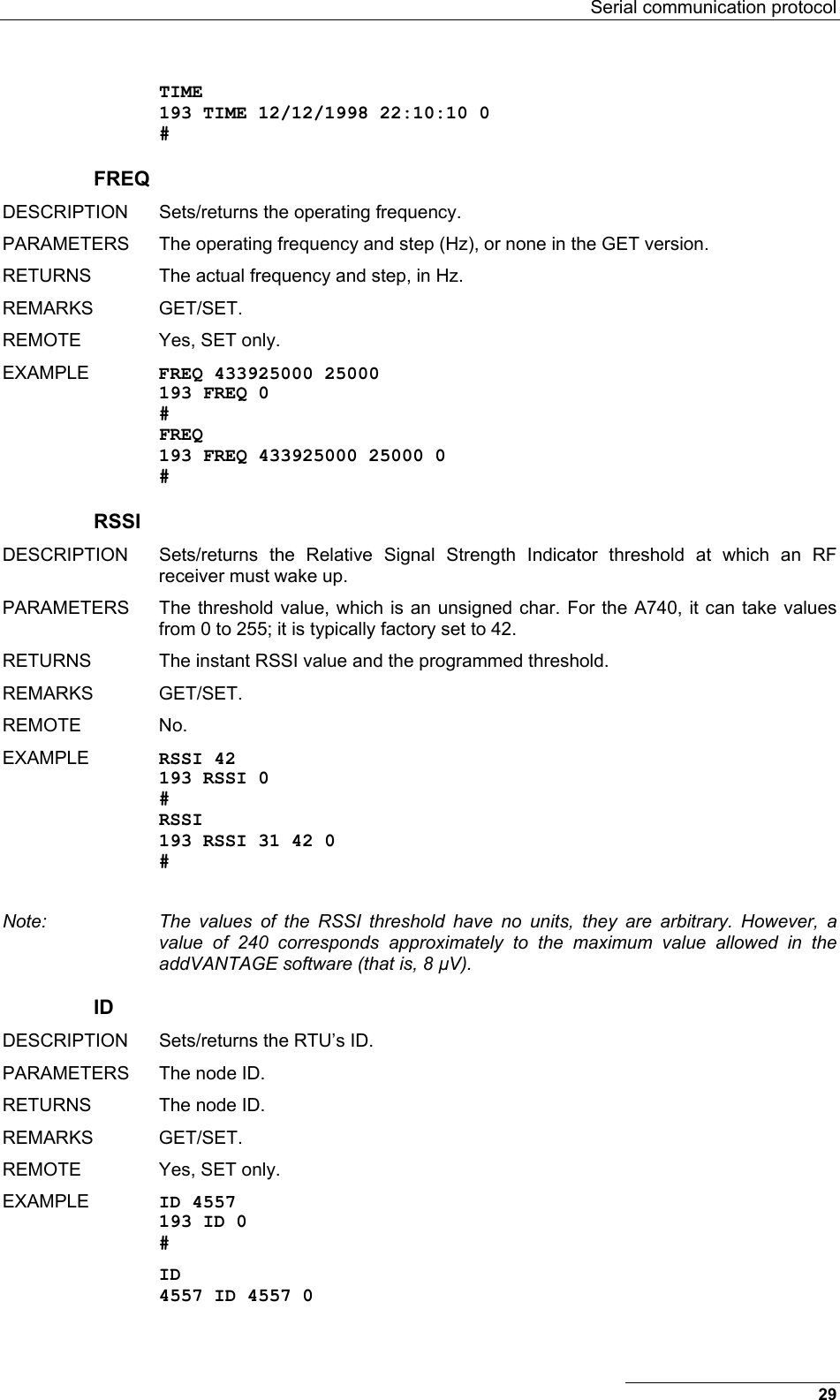
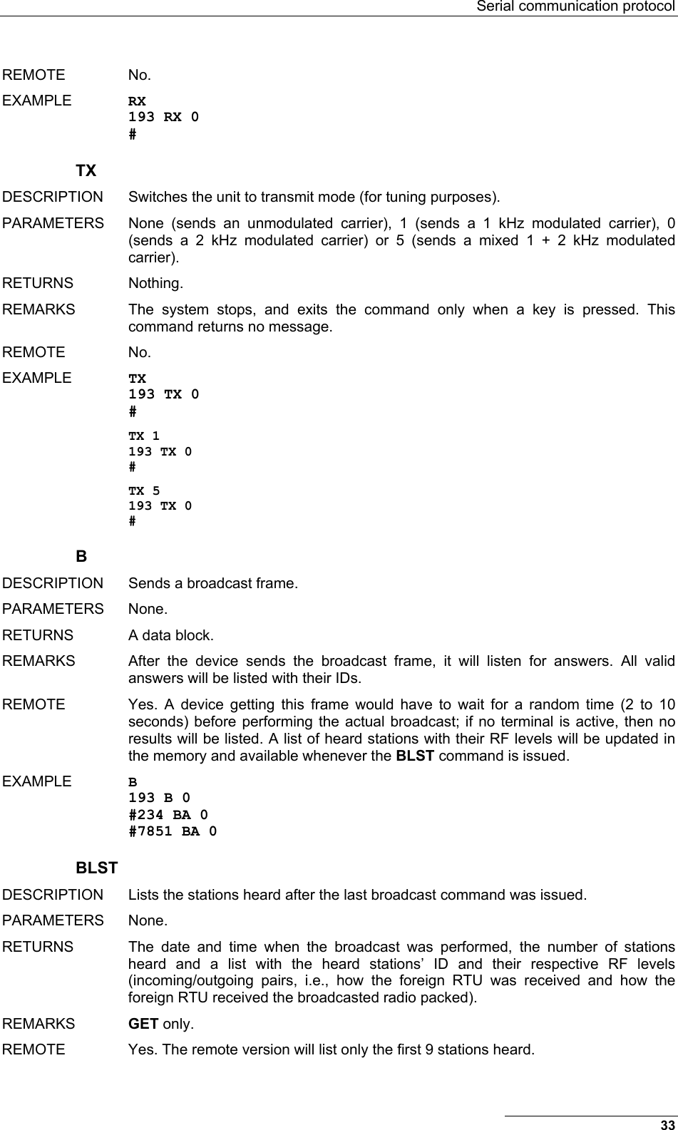
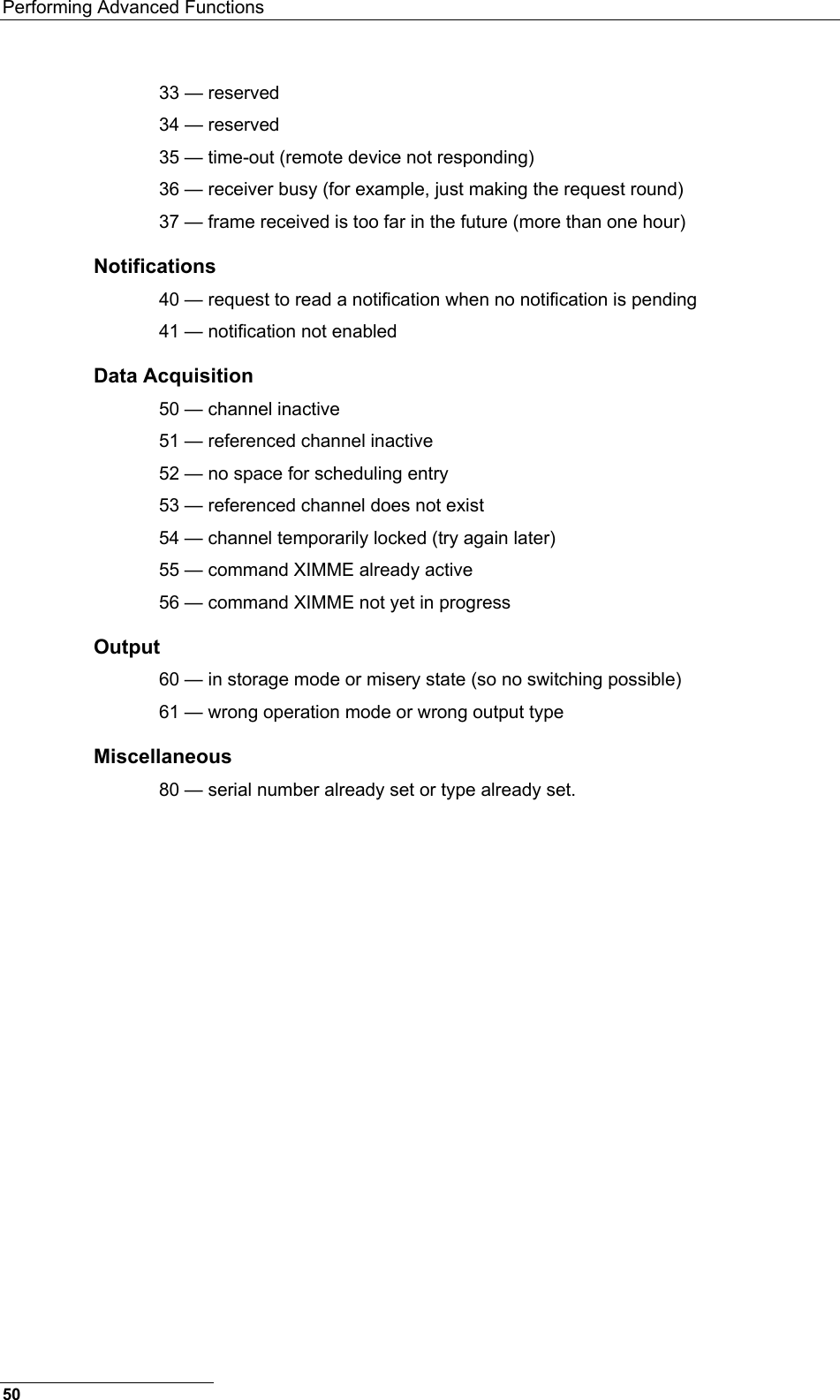
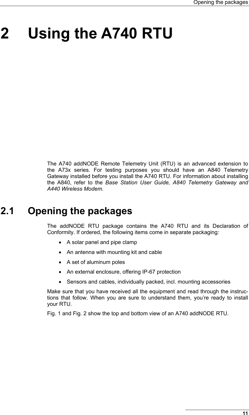
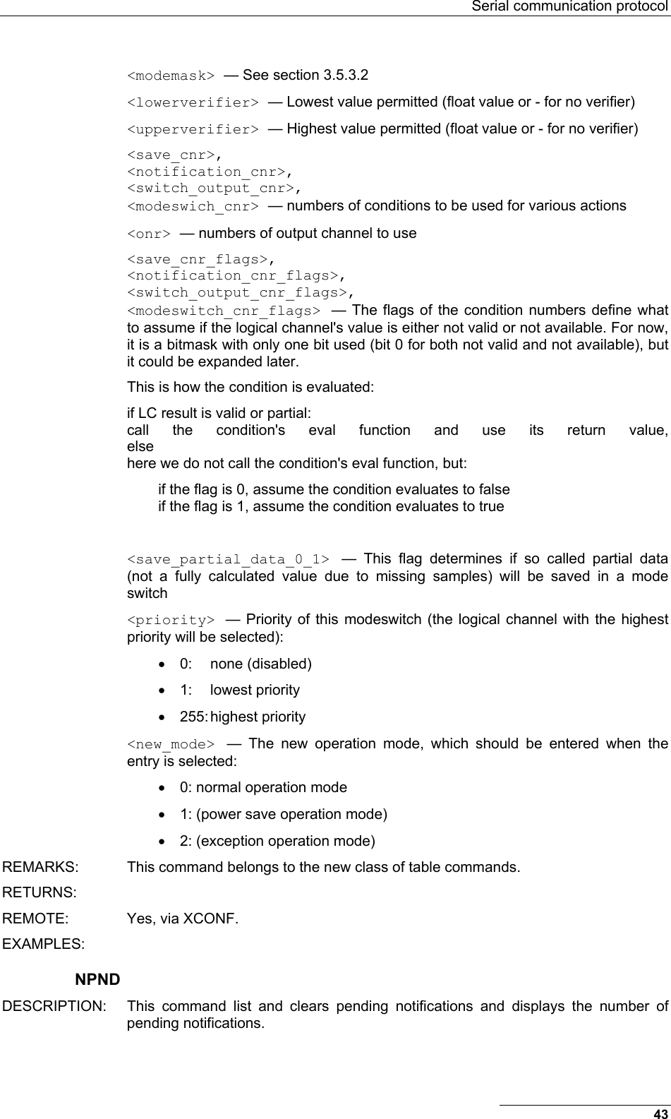
![Performing Advanced Functions EXAMPLE BLST 193 BLST 10/12/1999 12:15:04 4 2008 150 185 2003 177 210 6883 168 180 4027 220 255 # VER DESCRIPTION Requests the firmware version of the device. PARAMETERS None. RETURNS The current version. REMARKS GET only. REMOTE No. EXAMPLE VER 193 VER 1.3 0 # Note: This command is provided only for compatibility with older units. The host software may use this command to identify the unit it is communicating with. After detecting that the device supports this protocol, the INFO command must be used for further details, if available. MSTR DESCRIPTION: This command shows or sets the master receiver of the RTU, which is used for delivery of notifications. PARAMETERS: MSTR [ 0 | [ <hop_id1> [ ... [ <hop_id8> ] ] ] <destination_id> ] None, "0", of the route to the master receiver (including the master receivers id as last item in the list) REMARKS: GET/SET. RETURNS: The commands success or error code, or the route to the current master receiver. REMOTE: Yes, via XCONF. Particularly "MSTR 0" is designed for the remote case. EXAMPLES: MSTR 58 MSTR 58 42 0 # 123 XCONF MSTR 0 123 XCONF MSTR 0 # ROUTE DESCRIPTION: This command shows or sets the route to remote station. It is available on all RTUs and A440 devices. PARAMETERS: ROUTE [ <destination_id> [ <up_to_eight_relay_ids> ] ] None, or a route (with destination) containing up to eight intermediaries. When just the <destination_id> is given, then the route for this device is deleted. Depending on the size of the devices routing table, routes might have to be deleted before new routes are inserted. Currently the A740 can only hold one route at a time. 34](https://usermanual.wiki/Ott-Hydromet-Business-Unit-Adcon-Telemetry/A740-46/User-Guide-533367-Page-34.png)
![Serial communication protocol REMARKS: GET/SET. RETURNS: The commands success or error code. or the route table. REMOTE: No. EXAMPLES: ROUTE 42 58 ROUTE 0 # ROUTE 42 1 2 3 4 5 58 ROUTE 0 # ROUTE 42 1 2 3 4 5 0 # XCONF DESCRIPTION: This command transmits command strings for commands, which are suited for this mode of operation, to the targeted RTUs. Allowed commands are: CALC, COMP, COND, LC, MSTR, NPND, OC, OPMODE, PC, ROUTE, SWITCH, VER. PARAMETERS: XCONF <command-string> The command string with all parameters of the command to be transmitted to the remote device. REMARKS: The remote version sends a corresponding radio request, the local version acts a NOP. RETURNS: The reply string and the commands success or error code is returned. REMOTE: Yes, but remote only. EXAMPLES: 53 XCONF COND 0 53 XCONF COND 0 0 0 # XDATA DESCRIPTION: This command requests data for a list of logical channels for given timestamps. PARAMETERS: XDATA <Tsync> <flags> <Tlast> <last channel> <max values> <nr of channels> <channels ...> [ <max packet size> [ <Tto> ] ] <Tsync>: — Timestamp in UTC to synchronise the RTU. When zero, then no time synchronisation is requested. <flags>: — These can be a combination of all defined request and reply flags: • QUERY_FLAGS_MANDATORY (0x01): Request the RTU to honor all flags, or if it is not capable of honoring all given flags, to return an error. If this flag is not set, in its reply the RTU will clear capability flags for abilities it does not possess. • QUERY_FLAGS_NOSYSTEMTIME (0x02): This flag is a reply flag of the RTU to indicate that the system time needs to be set. • QUERY_FLAGS_NOTIFYPENDING (0x04): This flag is a reply flag of the RTU and indicates a pending notification. • QUERY_FLAGS_NEWESTVALUES (0x08): Request the RTU to only send the newest value for each requested logical channel. In order to retrieve the RTUs capabilities, sets all (known) flags except for the QUERY_FLAGS_MANDATORY flag and sets <Tlast> and <Tto> to the 35](https://usermanual.wiki/Ott-Hydromet-Business-Unit-Adcon-Telemetry/A740-46/User-Guide-533367-Page-35.png)
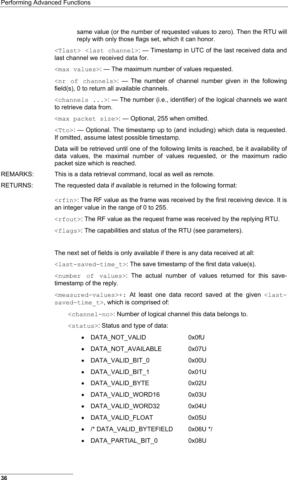
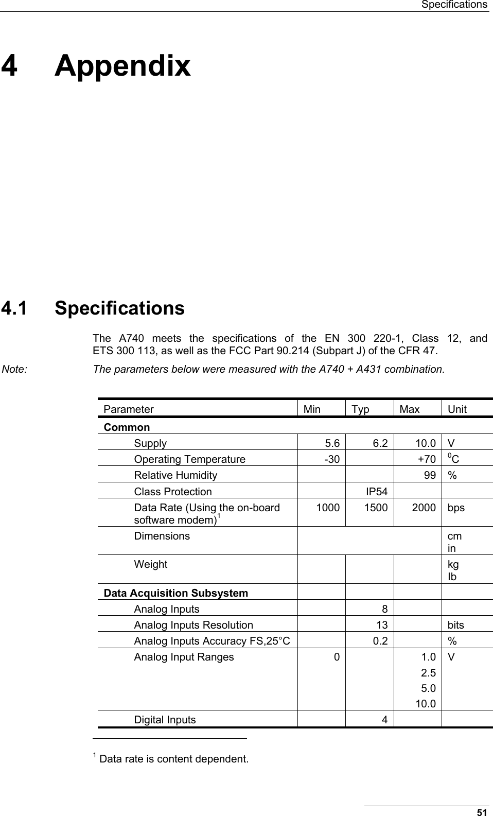
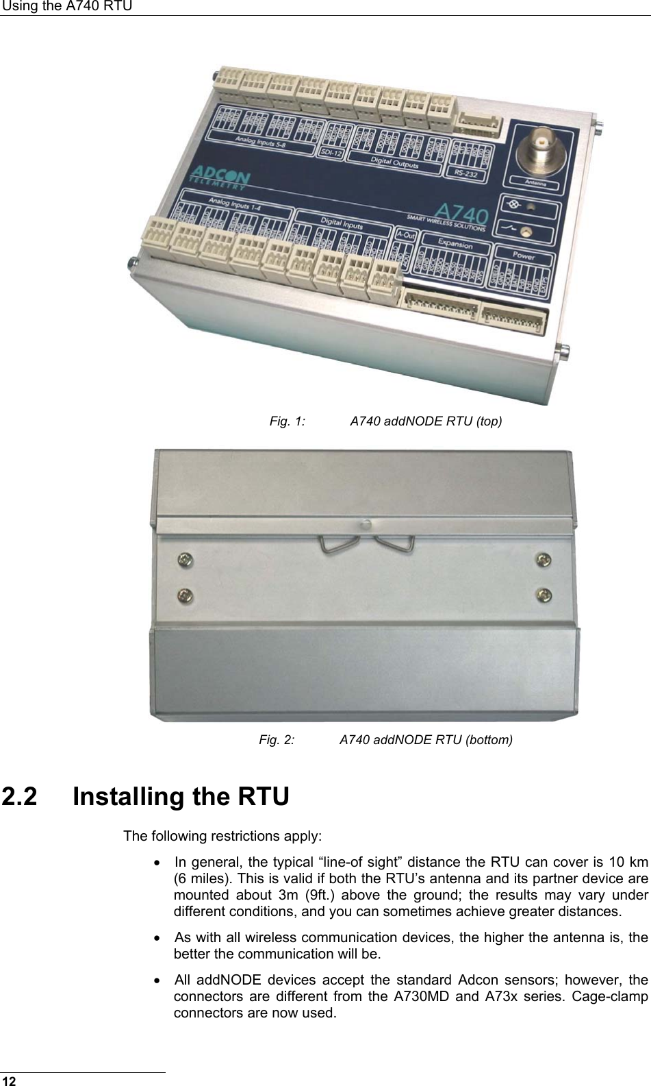
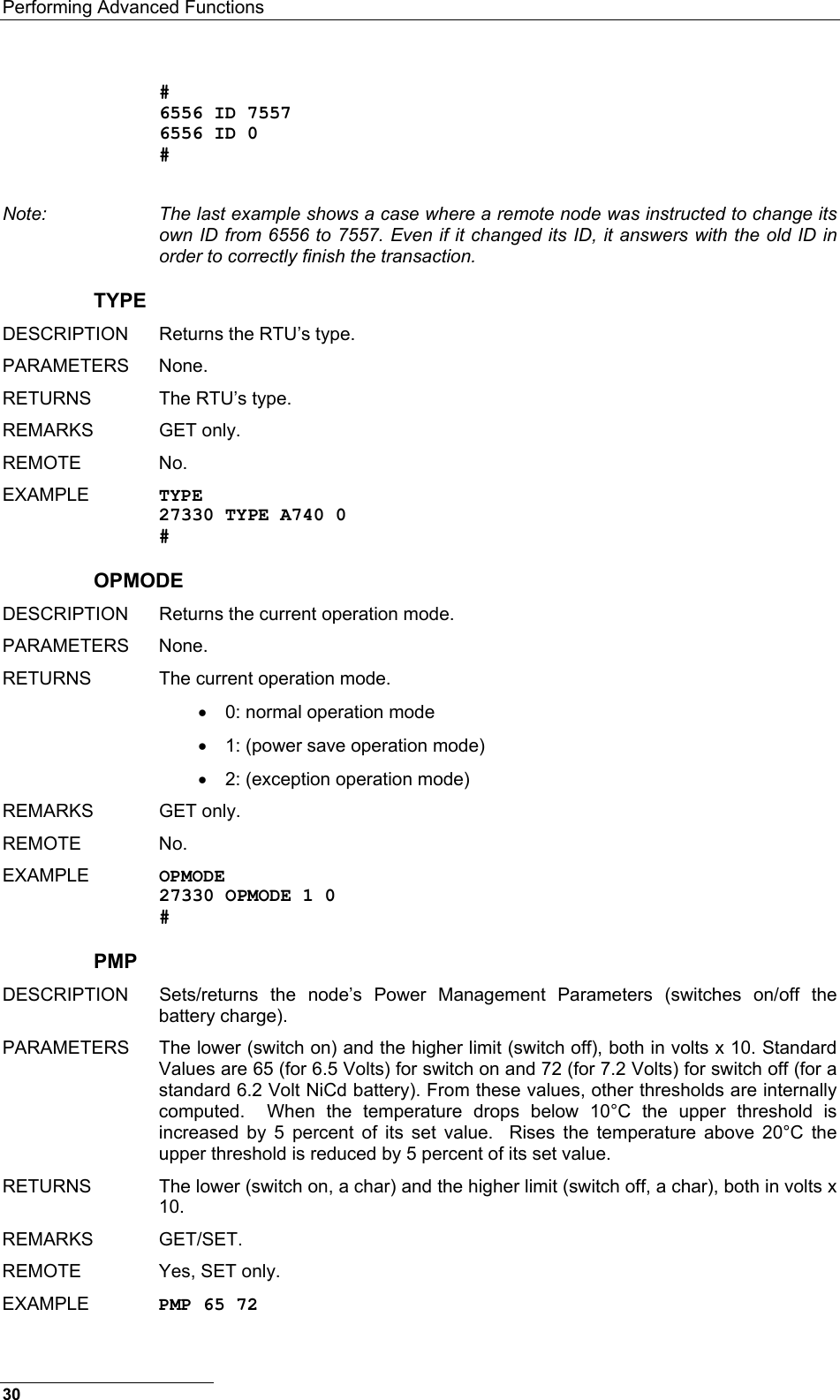
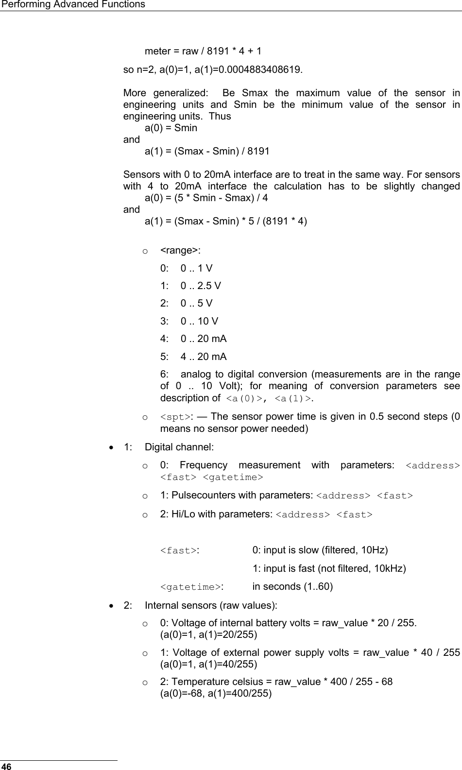
![Performing Advanced Functions XIMME { 0 | 1 } [ <max packet size> [ <pchan_nr> ... ] ] XIMME 2 <max packet size> <adc_nr> <range> <samplemode>: This specifies which values and how they are taken: • 0 .. converted data from configured physical channels • 1 .. raw data from configured physical channels • 2 .. raw data from all ADC channels of a given ADC (on motherboard of expansion board) <max packet size>: The maximum packet size for the reply. When 0, then the maximum number (255) is assumed. <pchan_nr>: A list of physical channel numbers used for filtering in sample modes 0 and 1. If no list is given, all configured channels are sampled and printed. The following parameters are used for samplemode 2 only: <adc_nr>: The address of the ADC, 0 for the ADC on the A740 motherboard, 1 to 3 for the respective expansion boards' ADCs. <range>: The range specifies the measurement range of the ADC and can be selected from: • 0: 0..1V • 1: 0..2.5V • 2: 0..5V • 3: 0..10V REMARKS: This command can also be used for calculating compensation values for the ADCs. Actually the <max packet size> is ignored for XIMME 2. RETURNS: XIMME 0 and XIMME one return the values of the requested or all physical channels either converted (samplemode 0) or raw (samplemode 1) as the tupple <physical channel no>, <type>, and <value> (see also XDATA). XIMME 2 returns the raw values of the selected ADC (<adc_nr>) with the selected measurement <range>. REMOTE: Yes. EXAMPLES: XIMME 2 0 0 3 59 XIMME 0 4262 915 1949 1727 1 1 0 -1 0 # 59 XIMME 0 0xf5 5.198392 1 0xf5 2.235382 2 0xf5 2.374152 3 0xf5 2.493485 4 0xff 5 0xf5 8169 6 0xf5 1830 7 0xf5 6907 8 0xf5 6.666667 9 0xf5 14.90196 10 0xf5 29.25489 11 0xf5 0 12 0xf5 0 13 0xf5 915 14 0xf5 -61.12451 15 0xf5 77.64618 0 # 59 XIMME 0 0xf5 4256 1 0xf5 1830 2 0xf5 7776 3 0xf5 8172 4 0xf5 1726 5 0xf5 8170 6 0xf5 1831 7 0xf5 6906 8 0xf5 85 9 0xf5 95 10 0xf5 62 11 0xf5 914 12 0xf5 914 13 0xf5 915 14 0xf5 536 15 0xf5 1831 0 # 38](https://usermanual.wiki/Ott-Hydromet-Business-Unit-Adcon-Telemetry/A740-46/User-Guide-533367-Page-38.png)
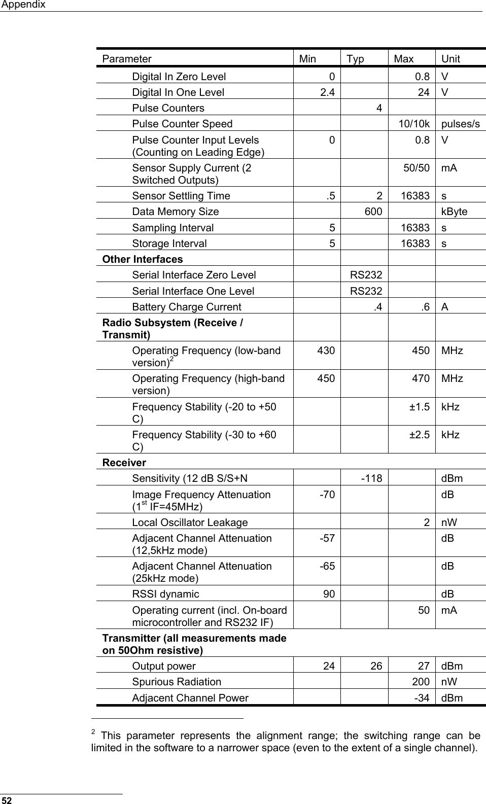
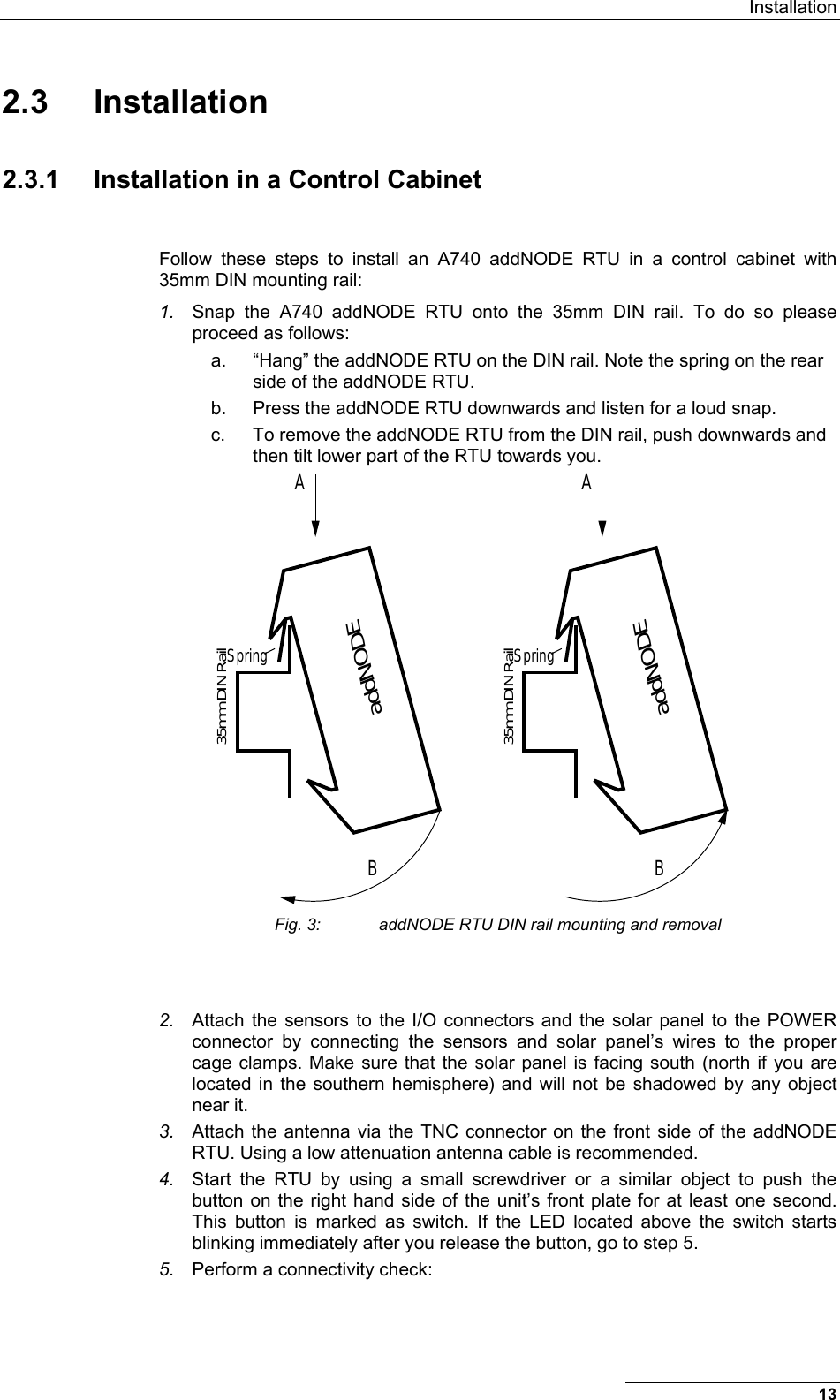
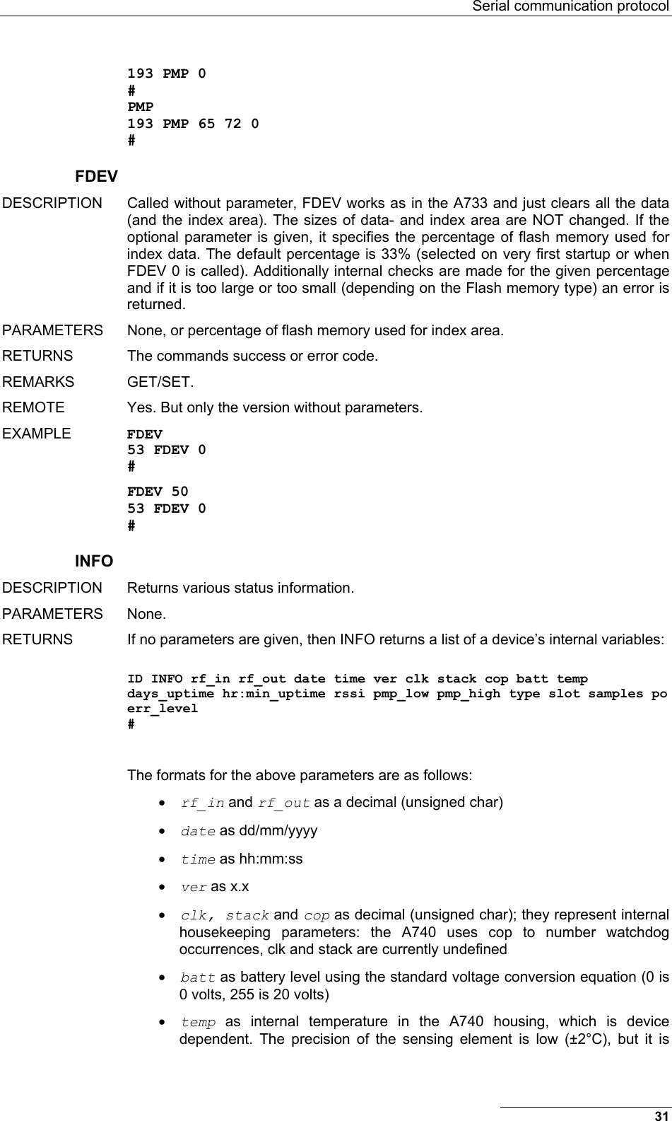
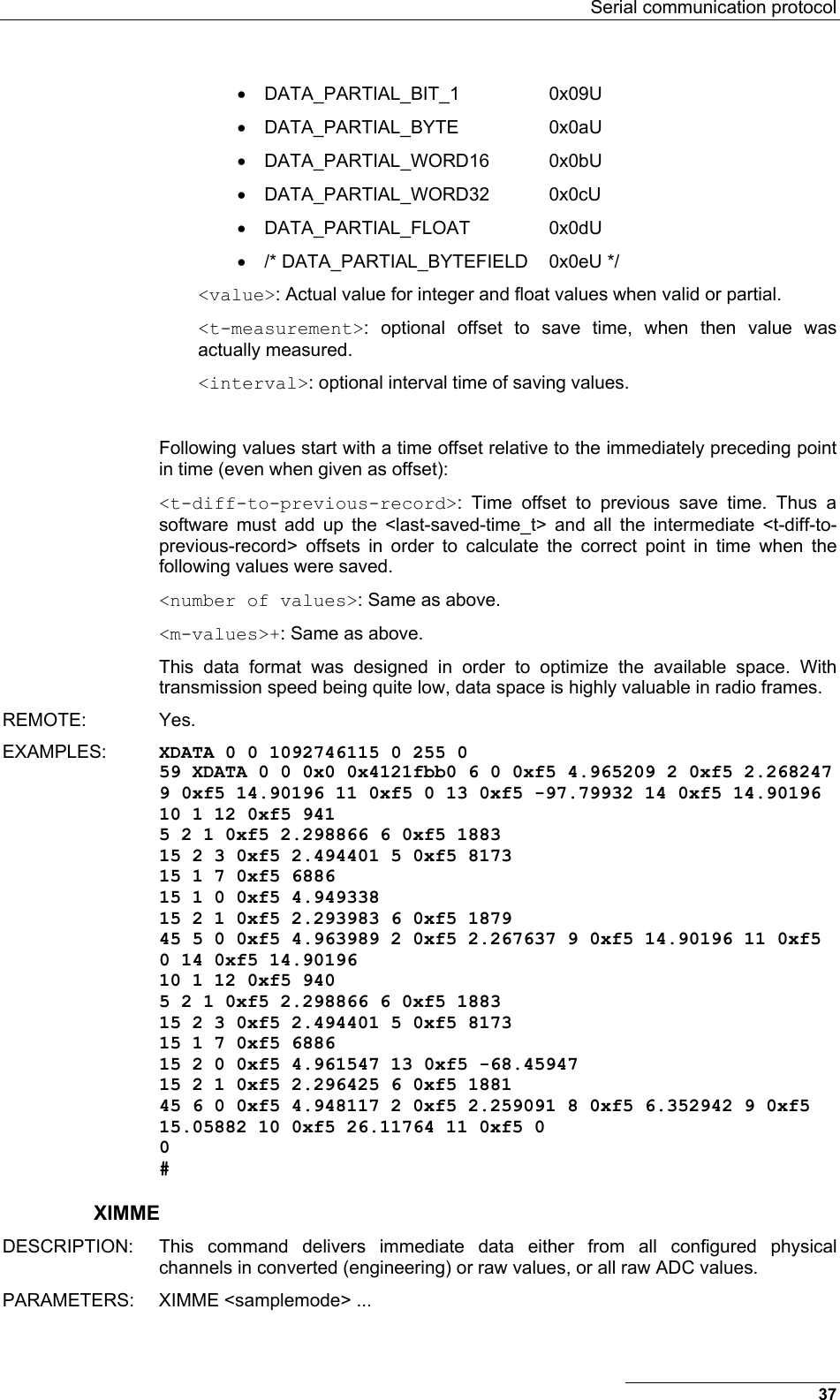
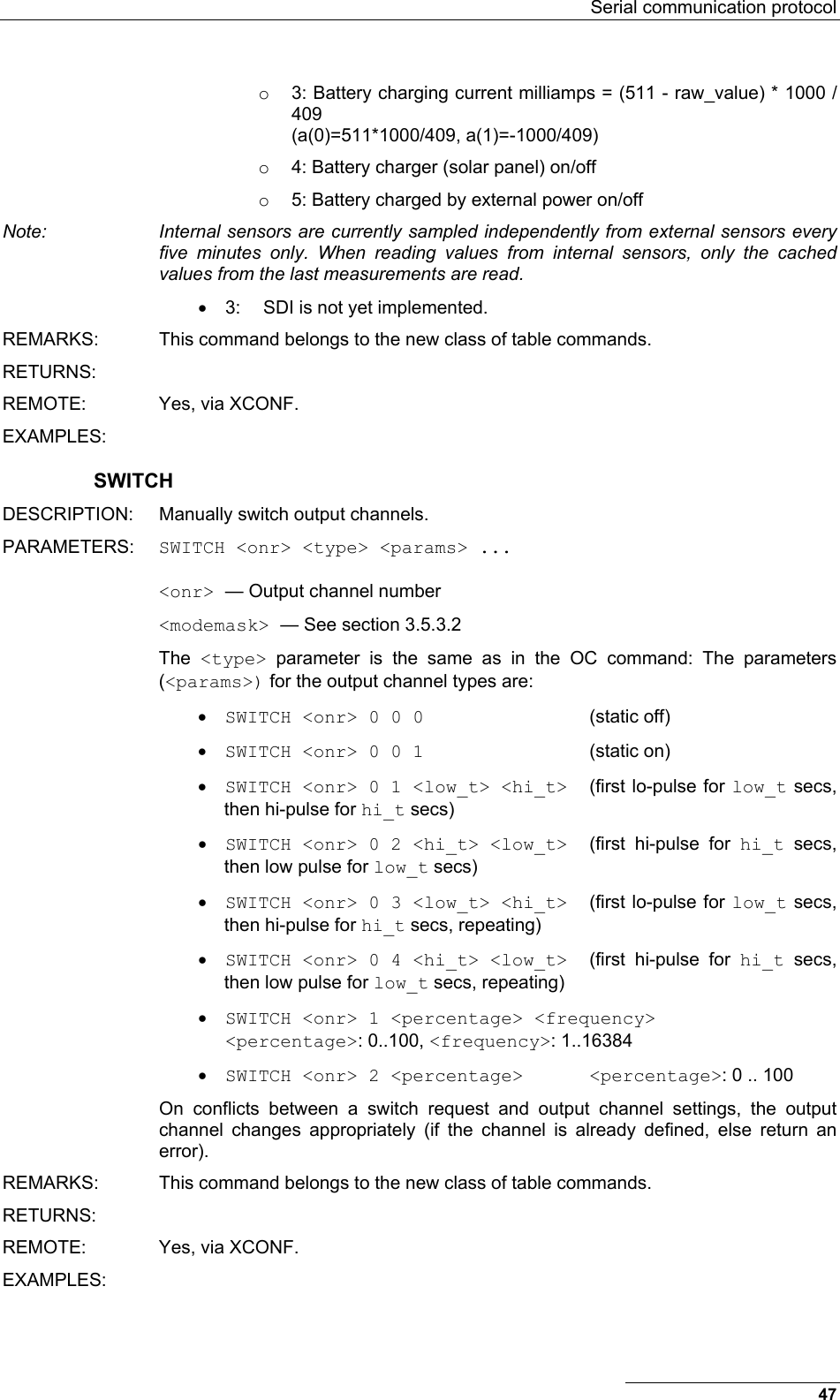
![Performing Advanced Functions • <command> + ... use next free id-nr for the config entry and return the id number • <command> <nr> configure given element/entry • <command> -<nr> delete given element/entry Most of the table commands accept a parameter <modemask> which is a bitmask and describes in which operation modes the specified descriptor will be active. The A740 has three operation modes and it starts up with mode number zero. Operation mode switches can be selected with the LC command (see below). The modes are referred to as “normal mode”, “power save operation mode” or mode 1, and “exception operation mode” or mode 2. Modes 1 and 2 can also be used with other meanings, since these modes have no hardwired or special meanings. Also note that “misery state”, which is activated when the battery voltage drops to 5.5V, is different from the aforementioned operating modes which only affect the operation of the data acquisition. The commands which use this syntax are marked as such in the descriptions remarks section. CALC DESCRIPTION: This command allows configuring the calculation functions used for data acquisition. Needed values are: the modes, in which the entry is active, the interval the calculations are carries out, a reference time the calculations (and data acquisitions) are aligned to, the number of and the individual (physical) input channels used, the number of and the individual (logical) output channels needed and finally the parameters to the calculation, e.g. the number of values to build am arithmetical mean value of. PARAMETERS: CALC <canr> <modemask> <interval> <Tref> <flags> <function> <nr_of_input_pcs> <pc> <mask for which outputs to use> <nr_of_output_lcs> <lc> <nr_of_params> [ <param> ... ] • <canr> — Calculation number, an integer value starting from 0. • <modemask> — A bitmask which specifies the modes, in which the entry is active. • <interval> — The interval in second within which the calculation has to deliver a complete value. • <Tref> — A timestamp (a time_t) giving the starting time and measurement time(s) for this calculation (reference point in time). A time value in the future will start measurements at this point in time, provided all the measurements can be taken in the remaining time. • <flags> — 0 acts as a NOP, 1 specifies, that the interval info for this calculation has to be saved, too. • <function> — A number specifying the calculation function used here. The meaning of the numbers is: o 0 arithmetical average (1 param = nr_of_samples) o 1 circular average (3 params, nr_of_samples, lowest value, highest value) o 2 minimum (1 param = nr_of_samples) o 3 maximum (1 param = nr_of_samples) 40](https://usermanual.wiki/Ott-Hydromet-Business-Unit-Adcon-Telemetry/A740-46/User-Guide-533367-Page-40.png)
![Serial communication protocol o 4 sum (1 param = nr_of_samples) o 5 first value (1 param = nr_of_samples) o 6 last value (1 param = nr_of_samples) • <nr_of_input_pcs> — The number of input channels used for this calculation. • <pc> — The physical channel(s) (currently only 1, later on up to 3) used as input(s). • <mask for which outputs to use> — A bitmask denoting the position in the list of logical channels used as outputs. • <nr_of_output_lcs> — The number of output channels used for this calculation. • <lc> — The logical channel(s) (currently only 1, later on up to 3) used as output(s). • <nr_of_params> — The number of parameters given to this calculation. • <param> — The parameters for this calculation. REMARKS: This command belongs to the new class of table commands. RETURNS: The commands error of success code, or the current configuration. REMOTE: Yes, via XCONF. EXAMPLES: COMP DESCRIPTION: This command sets one or lists (all or one) ADCs compensation information. The <adc_nr> specifies: • 0: ADC on A740 motherboard • 1: ADC on 1st expansion box • 2: ADC on 2nd expansion box • 3: ADC on 3rd expansion box The offset values are per analog input line, and the gain values are valid per gain, but are the same for all input lines and are used as a factor as in the formula: measured-value{line} * k{gain} / 8191 + d{line} PARAMETERS: COMP lists all ADCs compensation values COMP <adc_nr>[+] lists ADC <adc_nr>'s compensation values COMP <adc_nr> <4 gain(k) values> <8 offset (d) values> set ADC <adc_nr>'s compensation values COMP ? returns number of ADCs (both for max and used) REMARKS: This command belongs to the new class of table commands. But it cannot and does not implement the full syntax (e.g. deletions) RETURNS: REMOTE: Yes, via XCONF. EXAMPLES: 41](https://usermanual.wiki/Ott-Hydromet-Business-Unit-Adcon-Telemetry/A740-46/User-Guide-533367-Page-41.png)
![Performing Advanced Functions COND DESCRIPTION: This command allows specifying conditions and limits for those conditions, which can be used by logical channels to trigger saving, notification, etc. Condition number 0 is the default condition for the LC command and is thus per default set to "never" (type 0) and must not be changed. Attempts to do so result in error number 5 (parameter error). PARAMETERS: Depending on the condition type there is a varying number of parameters (see above). The meaning of the condition <type> is: • 0: never • 1: always • 2: upper limit (with hysteresis) • 3: lower limit (with hysteresis) • 4: within limits (with hysteresis) • 5: outside limits (with hysteresis) The parameters (if any) for the different condition types are always given in ascending order. COND <cnr> <type> COND <cnr> 0|1 COND <cnr> 2|3 <limitlo> <limithi> COND <cnr> 4|5 <lowerlimitlo> <lowerlimithi> <upperlimitlo> <upperlimithi> REMARKS: This command belongs to the new class of table commands. RETURNS: REMOTE: Yes, via XCONF. EXAMPLES: LC DESCRIPTION: This command specifies which actions to take, when a result value calculated from measurement value is available. Actions to take may be: • 1: saving of a value • 2: sending of a notification request to the master receiver • 3: switching of an output channel (see also OC command) • 4: operation mode change In addition there are the *_flags parameters, which specify when to call the condition and perform the action. PARAMETERS: LC <lnr> <modemask> <lowerverifier> <upperverifier> <save_cnr> <save_cnr_flags> [ <notification_cnr> <notification_cnr_flags> [ {<switch_output_cnr> <switch_output_cnr_flags> <onr> | 0 0 0} [ <modeswich_cnr> <modeswitch_cnr_flags> <save_partial_data_0_1> <priority> <new_mode> ] ] ] <lnr> — Logical channel number 42](https://usermanual.wiki/Ott-Hydromet-Business-Unit-Adcon-Telemetry/A740-46/User-Guide-533367-Page-42.png)
![Performing Advanced Functions PARAMETERS: None, a logical channel, a logical channel with timestamp. NPND: — list all logical channels with pending notifications NPND <nr> — lists the pending notification for the given logical channel NPND <nr>+ — list the next logical channel with a pending notification NPND ? — display the number of logical channel available and the number of logical channels with pending notifications NPND <nr> <timestamp> — clear given pending notification condition REMARKS: This command belongs to the new class of table commands. RETURNS: The commands success or error code, or the pending notification(s) as "channelnumber timestamp" pairs. REMOTE: Yes, via XCONF. EXAMPLES: NPND 58 NPND 1 1092442875 5 1092442123 0 # NPND 5 1092442123 58 NPND 0 # OC DESCRIPTION: This command configures output channels, which can be used for analog output or digital switching operations, either manually or automatically (see also SWITCH and LC command). PARAMETERS: OC <onr> <modemask> <type> <address> <onr> — Output channel number <modemask> — See section 3.5.3.2 <type>: — The type specifies the hardware parameters for the output channel: • 0 static hi/lo • 1 PWM • 2 analogue <address>: — consists of [module.]port, where • module: 1..3 for first to third expansion module • port: port name as printed on the label on the box (DOUT1..DOUT4, AOUT1 on base device, DOUT1..DOUT3 on expansion modules) REMARKS: This command belongs to the new class of table commands. RETURNS: REMOTE: Yes, via XCONF. EXAMPLES: 44](https://usermanual.wiki/Ott-Hydromet-Business-Unit-Adcon-Telemetry/A740-46/User-Guide-533367-Page-44.png)
![Serial communication protocol PC DESCRIPTION: This command configures the physical channels, which are the input stage of the data acquisition system. The physical channel descriptors contain verifiers, conversion parameters for converting measured values into engineering units and the hardware parameters needed for the actual sampling of the data. PARAMETERS: PC <pnr> <modemask> <lowerverifier> <upperverifier> <n> <a(0)> <a(n)> <chantype> <address> <parameters> <pnr> — Physical channel number <modemask> — See section 3.5.3.2 <lowerverifier>: — Lowest allowed value (float value or - for no verifier) <upperverifier>: — Highest allowed value (float value or - for no verifier) <n>: — The number of parameters used for the conversion (the current maximum is two). When <n> is zero, no conversion at all is done. When <n> is 1, then a table based conversion is done. Thus the meanings of <n> are: 0: no conversion, 1: table conversion (<a(0)> specifies the number of the table to be used), 2: linear conversion. <a(0)>, <a(1)>: — Floating point parameters for the conversion function, where <a(0)> is an offset, while <a(1)> is the factor (k * x + d). For analog-to-digital channels, these two values denote the lower and upper threshold for the analog to digital conversion (default 30% and 70% of full scale). These parameters are applied to the raw values of the sampled data (e.g. to analog values in the range from 0 (or slightly less) to 8191). If <n> is 1, then the one parameter (<a(0)>) is the number of the conversion table for the table based conversion. Currently there are 3 of those tables: 0: Gypsum Block Sensor Table 1: Leaf Wetness Sensor Table 2: Watermark Soil Moisture Sensor Table which can be used for the corresponding sensors. Note: For table based conversions the verifiers are applied before the conversion takes place (i.e., they are applied to the raw values). <address>: — consists of [module.]port, where • module: omitted for base device, 1..3 for first to third expansion module • port: port name as indicated on the devices top (AIN1..AIN8 or DIN1..DIN4 on base device and AIN1..AIN8 on expansion boards) <chantype>: — This parameter gives the type of the channel and also indicates which parameters are needed: • 0: Analog channel with parameters <range> <address> <spt> The ADC gives values in the range from 0 to 8191 (0V or 0mA give 0, the max. value of the selected range gives 8191, so 20mA give 8191, too). Assume a level sensor, which delivers a signal from 0V to 2.5V and 0V (or 0) is a level of 1 meter and 2.5V (or 8191) is a level of 5 meter. Thus the conversion formula is: 45](https://usermanual.wiki/Ott-Hydromet-Business-Unit-Adcon-Telemetry/A740-46/User-Guide-533367-Page-45.png)
![Performing Advanced Functions 3.5.3.3 Commands for status display and diagnosing CST DESCRIPTION: on all RTUs, clear internal statistics counters PARAMETERS: None STAT DESCRIPTION: on all RTUs, print all (or given task numbers) statistics counters PARAMETERS: STAT [<tasknr>] ESTAT DESCRIPTION: on all RTUs, print nonvolatile storage statistics, either in short form (no parameter given) or in a more verbose form (parameter 1 given) PARAMETERS: ESTAT [ 1 ] DUMP DESCRIPTION: dump starting from <startaddr> to <endaddr>. PARAMETERS: <startaddr> [<endaddr>]: If <endaddr> is omitted assume <startaddr> + 0xff (may be RAM, Data Flash; Program Flash only for development versions) PMSC DESCRIPTION: check or set/unset promiscuous mode on radio interface (very useful in combination with VERB) PARAMETERS: [ <0_or_1> ] VERB DESCRIPTION: check or set verbosity level. PARAMETERS: VERB [ <level> ]: 0 means quiet. PS DESCRIPTION: show process status of all CMX tasks (including CMX timer task, i.e. slot 0) or only for the given ids task. PARAMETERS: PS [ <taskid> ] 3.5.4 Notifications Notifications are frames sent asynchronously by devices that are otherwise slaves. Before a device can issue a notification, the notification must first be enabled, which is done by setting the notification condition for a logical channel. If the given notification condition occurs, the device will try to send the notification to the device configured using the MSTR command. Note: To avoid collisions, the device will wait a random time (up to 10 seconds) before sending the notification frame. If an end device is not able to send a notification due to radio propagation or other kind of communication problems, it will not send the notification again, but return 48](https://usermanual.wiki/Ott-Hydromet-Business-Unit-Adcon-Telemetry/A740-46/User-Guide-533367-Page-48.png)