Ott Hydromet Business Unit Adcon Telemetry A740-46 Telemetry transceiver User Manual 1
Adcon Telemetry GmbH Telemetry transceiver 1
User Manual

A740 addNODE
User Guide
Rel. 1.0.5WIP / March 2005

A
DCON TELEMETRY GMBH
INKUSTRASSE 24
A
-3400 KLOSTERNEUBURG
A
USTRIA
TEL: +43-2243-38280-0
FAX: +43-2243-38280-6
http://www.adcon.at
Proprietary Notice:
The Adcon logo, the A72x series and addIT™, the A730 series, addWAVE,
addRELAY, addVANTAGE, addVANTAGE Professional and AgroExpert™ are
trademarks or registered trademarks of Adcon Telemetry GmbH. All othe
r
registered names used throughout this publication are trademarks of thei
r
respective owners.
This publication contains confidential information, property of Adcon Telemetr
y
GmbH. Disclosure to third parties of the information contained herein is
prohibited. Neither the whole nor any part of the information contained in this
publication may be reproduced in any material form except with the prio
r
written permission of Adcon Telemetry GmbH.
Release 1.0.5WIP, March 2005
Copyright © 2004 by Adcon Telemetry GmbH.
All rights reserved.

Table of Contents
Table of Contents
1 Introduction .........................................................................7
1.1 About the A740 ................................................................................7
1.2 Compliance Statement and Warnings .............................................8
1.3 Conventions .....................................................................................9
2 Using the A740 RTU ..........................................................11
2.1 Opening the packages ...................................................................11
2.2 Installing the RTU...........................................................................12
2.3 Installation ......................................................................................13
2.3.1 Installation in a Control Cabinet .....................................................13
2.3.2 Stand-alone Installation .................................................................14
2.4 Configuring an A740 addNODE RTU in the
addVANTAGE software .................................................................15
2.5 Maintaining and servicing the RTU ................................................15
2.5.1 The RTU’s battery ..........................................................................15
2.5.2 Changing the battery......................................................................16
3 Performing Advanced Functions.....................................19
3.1 The RTU connectors......................................................................19
3.1.1 The POWER Connector.................................................................20
3.1.2 Serial Interface – RS-232...............................................................21
3.1.3 Analog Inputs .................................................................................21
3.1.4 Analog Output ................................................................................22
3.1.5 Digital Inputs ..................................................................................23
3.1.6 Digital Outputs................................................................................24
3.1.7 SDI-12 Interface.............................................................................25
3.1.8 Expansion Port...............................................................................25
3.2 The RTU’s Jumpers .......................................................................25
3

Table of Contents
3.3 Checking the RTU’s Status............................................................26
3.4 Communicating with the RTU ........................................................26
3.5 Serial communication protocol.......................................................27
3.5.1 General format of a command .......................................................27
3.5.2 General format of an answer .........................................................27
3.5.3 Commands Accepted by the A740 addNODE...............................28
CMDS.............................................................................................28
TIME...............................................................................................28
FREQ .............................................................................................29
RSSI...............................................................................................29
ID....................................................................................................29
TYPE..............................................................................................30
OPMODE .......................................................................................30
PMP ...............................................................................................30
FDEV..............................................................................................31
INFO...............................................................................................31
RX ..................................................................................................32
TX...................................................................................................33
B.....................................................................................................33
BLST ..............................................................................................33
VER................................................................................................34
MSTR .............................................................................................34
ROUTE...........................................................................................34
XCONF...........................................................................................35
XDATA ...........................................................................................35
XIMME ...........................................................................................37
3.5.3.1 Data Acquisition, Outputs and Operation Modes...........................39
3.5.3.2 Table commands............................................................................39
CALC..............................................................................................40
COMP ............................................................................................41
COND.............................................................................................42
LC...................................................................................................42
NPND .............................................................................................43
OC..................................................................................................44
PC ..................................................................................................45
SWITCH .........................................................................................47
3.5.3.3 Commands for status display and diagnosing ...............................48
CST ................................................................................................48
STAT ..............................................................................................48
ESTAT............................................................................................48
DUMP.............................................................................................48
PMSC.............................................................................................48
VERB .............................................................................................48
PS ..................................................................................................48
3.5.4 Notifications....................................................................................48
3.5.5 Returned errors list ........................................................................49
4

Table of Contents
Command line interpreter ..............................................................49
Device descriptors and storage handler ........................................49
Real time clock...............................................................................49
Radio interface ...............................................................................49
Notifications....................................................................................50
Data Acquisition .............................................................................50
Output ............................................................................................50
Miscellaneous ................................................................................50
4 Appendix ............................................................................ 51
4.1 Specifications .................................................................................51
5 Index ................................................................................... 55
5

About the A740
1 Introduction
This manual explains the hardware aspects of Adcon’s A740 addNODE Remote
Telemetry Unit, including installation issues and certain parameter configurations.
The manual is divided as follows:
• "Introduction", which gives some general information and document
conventions.
• "Using the A740 RTU", which details the installation and use of the remote
telemetry unit.
• "Performing Advanced Functions", which discusses technical information
for the advanced user.
• "Specifications", which describes operating parameters for the devices.
1.1 About the A740
The A740 addNODE Remote Telemetry Unit (RTU) is a portable low-power,
medium-range telemetry device capable of sampling up to 8 analog and 4 digital
inputs. The analog inputs offer a resolution of 14bit (13bit+Signbit). The digital
inputs can be used as fast (up to 10 kHz) or slow (<10Hz) counters or frequency
measuring inputs.
Furthermore 4 protected digital low-side switches and one analog (0-2.5V, 10Bit)
output are available. The digital outputs can be used in conjunction with the PWM
capabilities of the CPU.
A V24/RS232 serial interface is also built in, allowing for configuration, firmware
upgrade or communication. An SDI-12 interface, capable of supplying 5.5-
7V/100mA sensor power, is available on the A740, but is not yet operational. The
SDI-12 functionality will be included into the firmware of the A740 soon.
The A740 RTUs incorporate an A431 radio module operating in the 430 to 470
MHz range, making it adaptable to most radio communication regulations in the
world. The output power is variable up to 0.5 W, while the modulation is narrow-
band FM (6.25, 12.5 or 25 kHz channel spacing).
Due to its construction, as well as to the software controlling it, the power
consumption is extremely low. The RTUs operate from a built-in NiCd 6.2 Volt
7

Introduction
rechargeable battery, which is charged using either a solar panel or an external
power supply adapter. A special configuration may be implemented where no
internal battery is used, but the power is rather obtained exclusively over an
external connector.
Depending on the topography it ensures a reliable wireless connection to an A840
Telemetry Gateway device up to 20 km (12 miles).
1.2 Compliance Statement and Warnings
The A740 addNODE must not be used with any antenna other than the one
supplied by Adcon (or an antenna with identical technical specifications).
A minimum distance of 18cm to the antenna is required in order to comply with
basic safety restrictions. In conformity with the EC Parliament recommendations
1999/519/EG 28V/m is the reference value for the frequency range used. By
adhering to any and all recommended reference levels, the compliance to basic
restrictions serving the protection of the general public against electromagnetic
fields is ensured.
This device is notified in the following countries:
Austria, Belgium, Denmark, Finland, France, Germany, Greece, Hungary,
Italy, Ireland, The Netherlands, Norway, Poland, Portugal, Spain, Sweden,
Switzerland, United Kingdom
In some countries individual user licences and frequency allocations need to be
applied for. Please consult your dealer for further information.
Please be aware that the country denominations as shown on the label are
indicative only and might not refer to your specific location. If you are not located
within one of these countries a different frequency might be programmed into the
device according to the frequency allocations in your country. Please be also
aware that using this device in other countries than the one it was originally
supplied for might be unlawful and void the devices type approval.
Warning as required by FCC 15.21: any manipulations on this device other than
mentioned in this manual void the FCC type approval.
8

Conventions
1.3 Conventions
Certain conventions apply in this documentation.
Italics
Indicate the text is variable and must be substituted for
something specific, as indicated in the explanation. Italics
can also be used to emphasize words as words or letters as
letters
Bold
Indicates special emphasis of the text. Also indicates menu
names and items in a window.
fixed font
Indicates characters you must type or system messages.
FileSave
Indicates menu selection. For example, select the File
menu, then the Save option.
Note
Indicates information of interest. Notes appear after the
information they apply to.
CAUTION
Indicates that you may get unexpected results if you don’t
follow the instructions. Cautions appear before the
information they apply to.
WARNING
Indicates danger to yourself or damage to the device if you
don’t follow the instructions. Warnings appear before the
information they apply to.
9

Opening the packages
2 Using the A740 RTU
The A740 addNODE Remote Telemetry Unit (RTU) is an advanced extension to
the A73x series. For testing purposes you should have an A840 Telemetry
Gateway installed before you install the A740 RTU. For information about installing
the A840, refer to the Base Station User Guide, A840 Telemetry Gateway and
A440 Wireless Modem.
2.1 Opening the packages
The addNODE RTU package contains the A740 RTU and its Declaration of
Conformity. If ordered, the following items come in separate packaging:
• A solar panel and pipe clamp
• An antenna with mounting kit and cable
• A set of aluminum poles
• An external enclosure, offering IP-67 protection
• Sensors and cables, individually packed, incl. mounting accessories
Make sure that you have received all the equipment and read through the instruc-
tions that follow. When you are sure to understand them, you’re ready to install
your RTU.
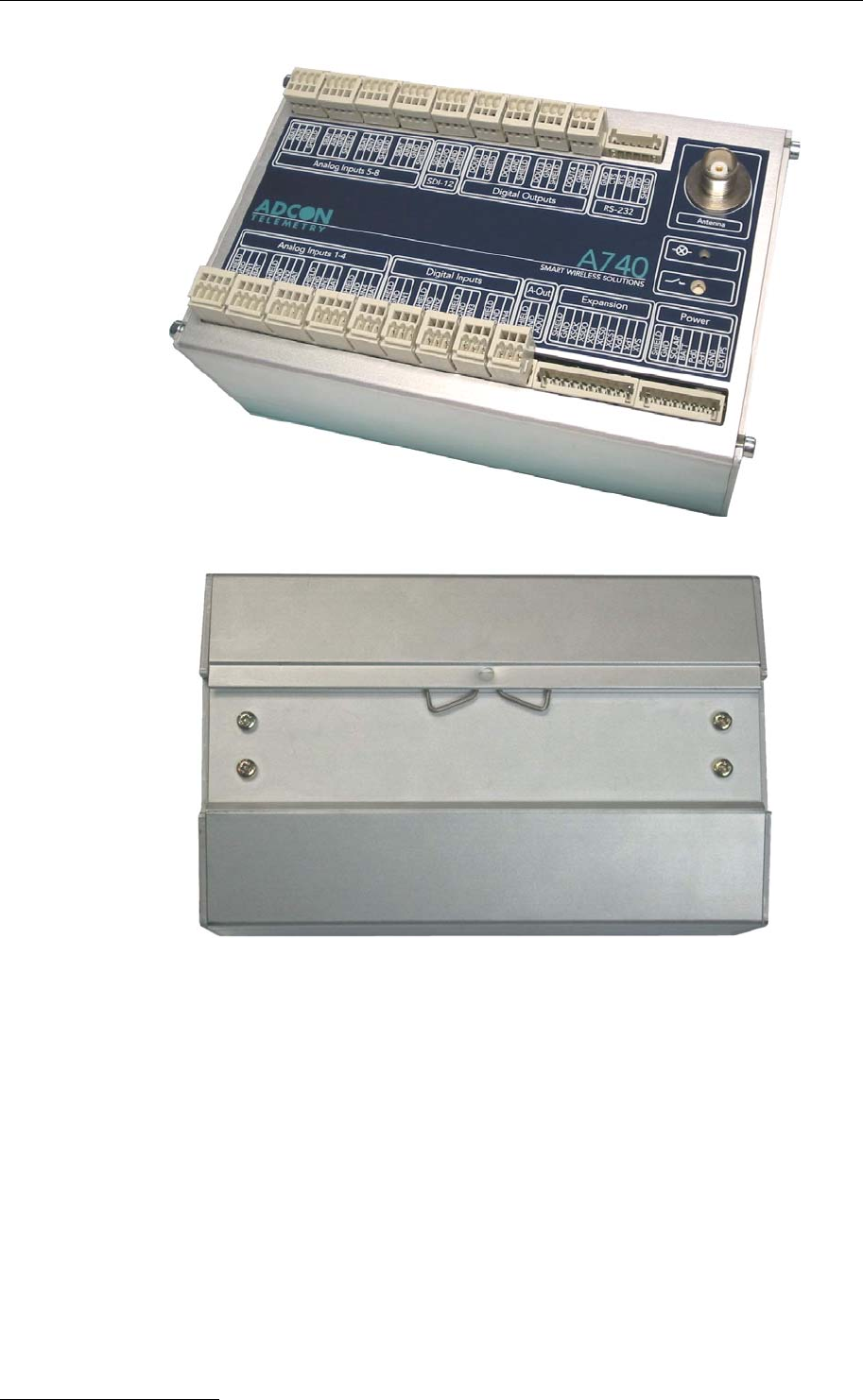
Fig. 1 and Fig. 2 show the top and bottom view of an A740 addNODE RTU.
11
Using the A740 RTU
Fig. 1: A740 addNODE RTU (top)
Fig. 2: A740 addNODE RTU (bottom)
2.2 Installing the RTU
The following restrictions apply:
• In general, the typical “line-of sight” distance the RTU can cover is 10 km
(6 miles). This is valid if both the RTU’s antenna and its partner device are
mounted about 3m (9ft.) above the ground; the results may vary under
different conditions, and you can sometimes achieve greater distances.
• As with all wireless communication devices, the higher the antenna is, the
better the communication will be.
• All addNODE devices accept the standard Adcon sensors; however, the
connectors are different from the A730MD and A73x series. Cage-clamp
connectors are now used.
12
Installation
2.3 Installation
2.3.1 Installation in a Control Cabinet
Follow these steps to install an A740 addNODE RTU in a control cabinet with
35mm DIN mounting rail:
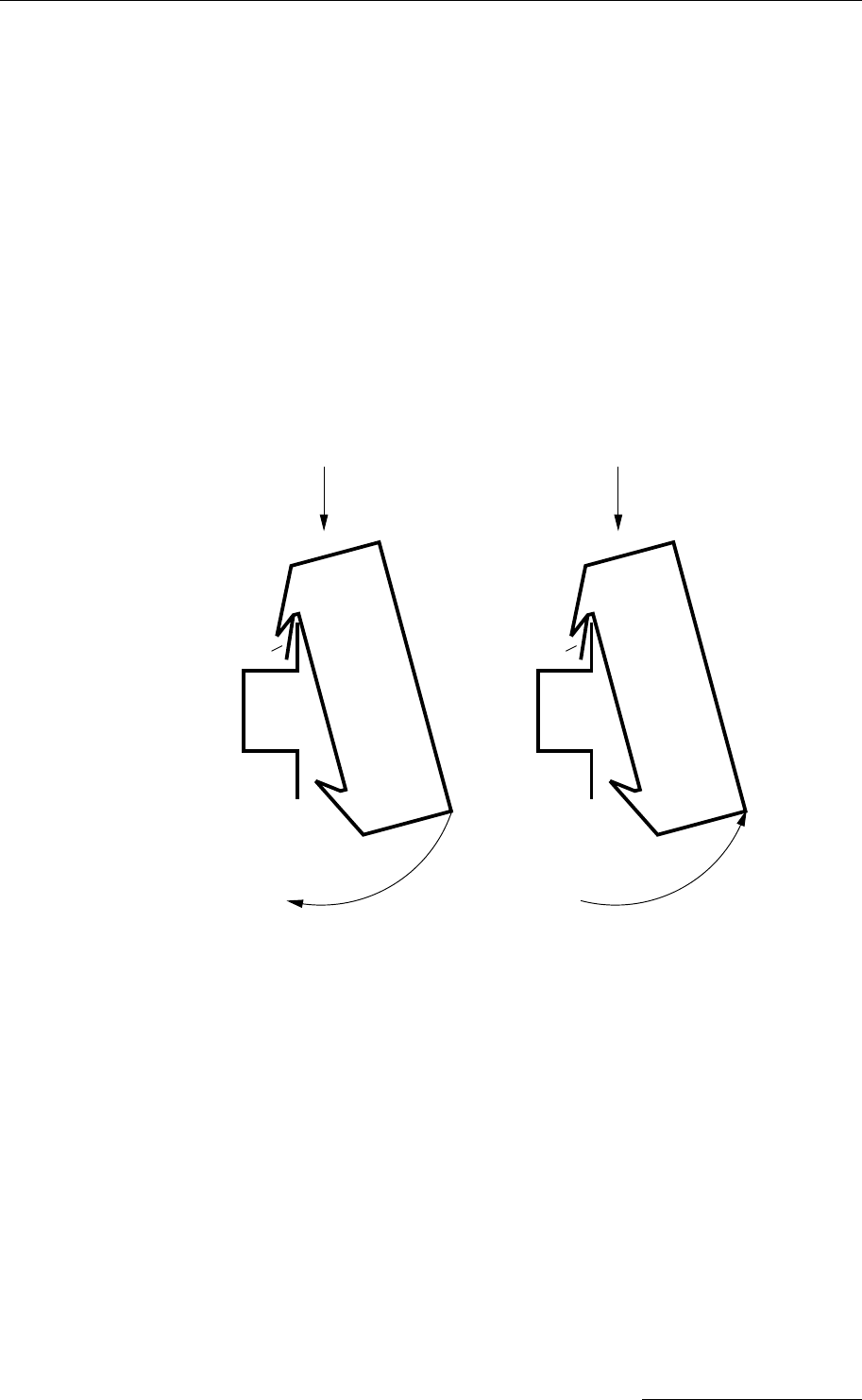
1. Snap the A740 addNODE RTU onto the 35mm DIN rail. To do so please
proceed as follows:
a. “Hang” the addNODE RTU on the DIN rail. Note the spring on the rear
side of the addNODE RTU.
b. Press the addNODE RTU downwards and listen for a loud snap.
c. To remove the addNODE RTU from the DIN rail, push downwards and
then tilt lower part of the RTU towards you.
A
B
35mm DIN Rail
addNODE
Spring
A
B
35mm DIN Rail
addNODE
Spring
Fig. 3: addNODE RTU DIN rail mounting and removal
2. Attach the sensors to the I/O connectors and the solar panel to the POWER
connector by connecting the sensors and solar panel’s wires to the proper
cage clamps. Make sure that the solar panel is facing south (north if you are
located in the southern hemisphere) and will not be shadowed by any object
near it.
3. Attach the antenna via the TNC connector on the front side of the addNODE
RTU. Using a low attenuation antenna cable is recommended.
4. Start the RTU by using a small screwdriver or a similar object to push the
button on the right hand side of the unit’s front plate for at least one second.
This button is marked as switch. If the LED located above the switch starts
blinking immediately after you release the button, go to step 5.
5. Perform a connectivity check:
13

Using the A740 RTU
d. Push the button and keep it pushed. The LED above the button will
start blinking in half second intervals. If the LED blinks in two second
intervals, either the battery is low (< 5.5V) or the POWER connector is
not connected or not properly wired. Keep the button pushed for 2
seconds until the blinking intervals change to 4 very short blinks (1/8th
of a second followed by a pause of 1/8th of a second).
e. Now release the button and watch the LED.
f. When the RTU receives the first answer to its broadcast it will light the
LED for 4 seconds. Up to ten seconds later the number of station calls
received will be reported by a half second blink per station.
g. Finally 4 very short blinks indicate the end of the connectivity test.
Should the end of the connectivity test be signalled without any sign of
having received answers to station’s broadcast, you are not within the
radio range of other Adcon devices. This could be remedied by e.g.
increasing the antenna mounting height or move the station a few
meters away, if you are sure that there are other RTUs nearby.
This completes the installation of your addNODE RTU. Be sure to make a note of
the following information because you’ll need it when you configure the device in
the software:
• Serial number for each RTU
• Type and channel information of sensors connected to each RTU
2.3.2 Stand-alone Installation
For an outdoor installation of the addNODE RTU you need an IP-67 enclosure with
an integrated 35mm DIN rail. Such an enclosure can be provided by Adcon
Telemetry.
1. Assemble the mast from the set of poles.
2. Put a “pounder cap” on top of first pole segment it drive its beveled end into the
ground using a sledge hammer. The deeper down you get the more stability
you will have. In windy areas or soft solid guy wires will add additional safety to
prevent the mast from tilting or falling over.
3. Fasten the solar panel onto the aluminum pole with the pipe clamp provided.
Make sure that the panel is facing south (north if you are located in the
southern hemisphere) and is clear of any object that might cast its shadow
onto it.
Note: The solar panel can be mounted under or behind the addNODE RTU, but make
sure that the RTU does not shadow the panel.
4. Fasten the IP67 enclosure to the rod in a comfortable height using the clamps
supplied.
5. Proceed with the procedure as described in 2.3.1.
6. Attach the sensors to the I/O connectors and the solar panel to the POWER
connector by connecting the sensors and solar panel’s wires to the proper
cage clamps.
14

Configuring an A740 addNODE RTU in the addVANTAGE software
2.4 Configuring an A740 addNODE RTU in the
addVANTAGE software
To configure the addNODE RTU with an A840 Telemetry Gateway and the
addVANTAGE 4 Pro software, check the Base Station, Telemetry Gateway A840
and Wireless Modem A440 User Guide.
2.5 Maintaining and servicing the RTU
The A740 unit needs virtually no maintenance. The only part which might have to
be changed during the devices lifetime is the internal battery.
Since some sensors tend to drift over time make sure they are properly maintained
and calibrated or replaced if needed.
2.5.1 The RTU’s battery
The internal battery supplies 6.2 volts and consists of a 5-cell NiCd pack. The
internal electronics manage the battery charging/discharging process, ensuring it a
long life. This approach, coupled with a remarkably low average consumption
(some mere 6 mW for the standard RTU and 15 mW for the GSM RTU (not yet
available/Oct. 2004), allows an addNODE RTU to operate at least two weeks on a
fully charged battery, if the following conditions apply:
• The channel has moderate radio activity, with requests every 15 minutes.
• Total consumption of attached sensors is 100 mA or less.
• The sensors are not sampled more often than once per minute and only
one value per sensor is stored in the internal memory every 15 minutes.
The following table shows the A740 addNODE’s expected operating time on a fully
charged battery under various conditions. The sensor consumption does not
exceed 100 mA.
Radio Activity Sensor Sampling
(samples/15 min)
Average
Consumption (mA)
Estimated
Operation (days)
No No sensors 0.85 132
Low No sensors 2.8 40
Heavy No sensors 5 22
Low 3 4.2 26
Low 15 6.3 17
Heavy 15 9 12
Table. 1: addNODE Operating Time on a full Battery Charge
Note: Low radio activity means that one base station and between one and three RTUs
are active on the same operating frequency as the addNODE remote station.
Heavy radio activity means that approximately 30 devices are on the same
channel. However, no routing is used.
If for some reason (wear-out or accident) the battery loses its capacity (noted in the
software with repeated “Battery low” messages), it must be replaced. Make sure,
15
Using the A740 RTU
though, that the problem is really due to the battery and not to a defective or dirty
solar panel or a sensor drawing too much current.
Adcon highly recommends checking the solar panel’s condition and clean it
frequently Rain drops can splash thin layers of dust or soil onto the panels, thus
reducing their power output. The surrounding vegetation can also lower the panel’s
efficiency.
2.5.2 Changing the battery
If you have verified that the battery needs to be replaced, follow these steps to do
so:
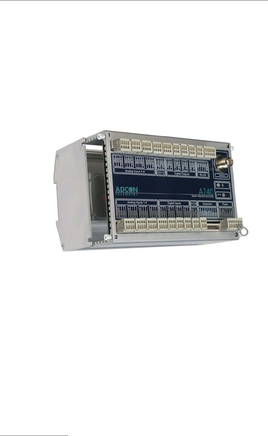
1. Open the lid by unscrewing the four top screws on the side plates of the
addNODE RTU, and then remove the top as shown in Fig. 4.
Fig. 4: Removing the addNODE Lid
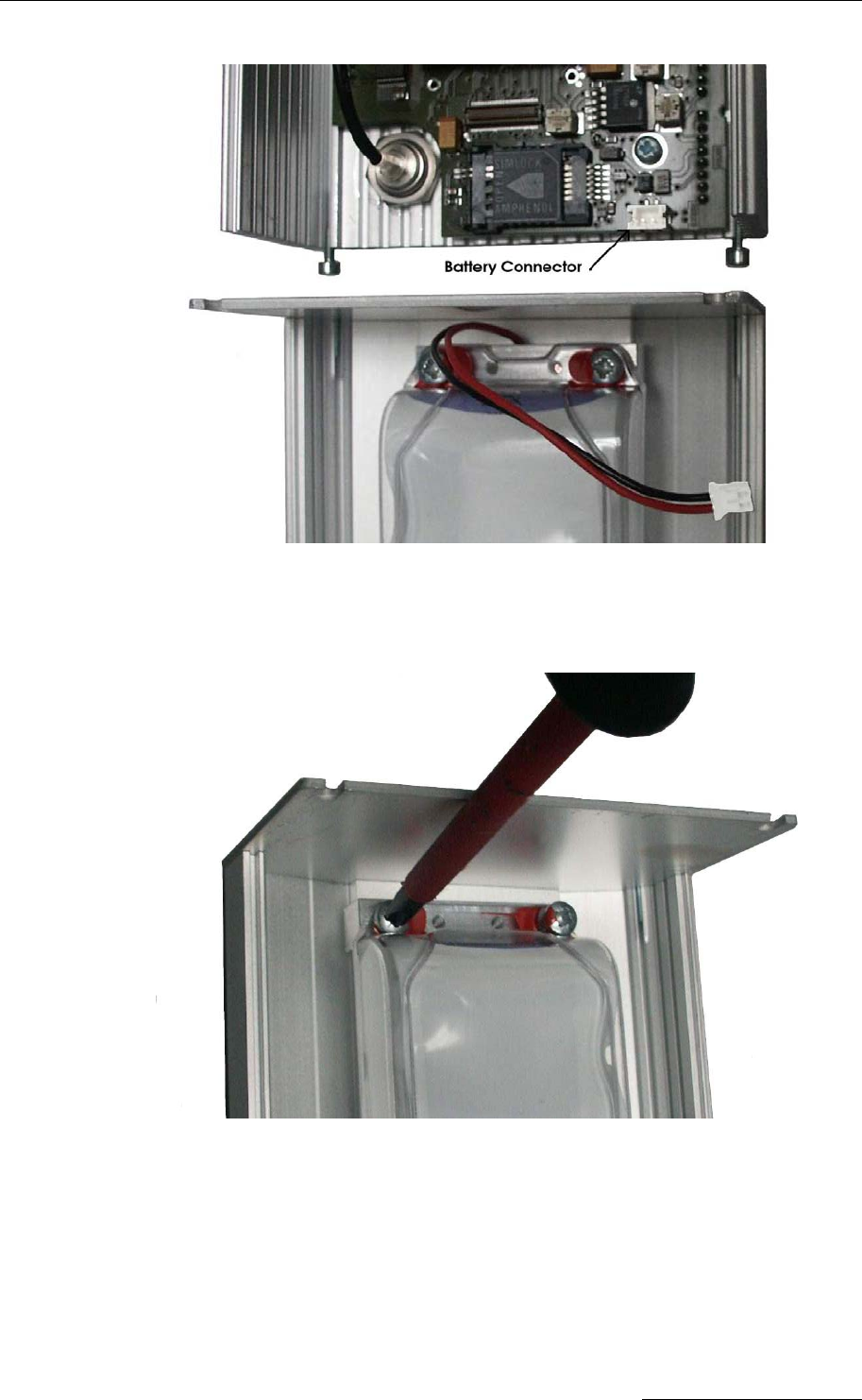
2. The battery pack is connected to the electronics board by means of a PCB
connector. Remove the battery pack’s plug from the PCB connector, as shown
in Fig. 5.
16
Maintaining and servicing the RTU
Fig. 5: Unplugging the PCB Connector
3. Unscrew the four screws of the plastic cover that holds the battery pack in
place, then remove the cover. Fig. 6 shows the A740 battery pack inside the
RTU.
Fig. 6: A740 Battery Pack
4. Remove the battery pack and replace it with a new one (ask your Adcon
distributor).
5. Replace the plastic cover and secure it tightly with the four screws.
6. Insert the battery plug into the PCB connector.
7. Mount the top.
8. Screw the four screws back in, applying a moderate force.
17

Using the A740 RTU
18

The RTU connectors
3 Performing Advanced
Functions
With the appropriate knowledge, you can configure the addNODE devices in the
field by using a HyperTerminal window. To configure the RTU, you will need a
special serial cable adapter (not supplied, available from Adcon).
Do not try to configure your addNODE devices if you are not sure what to do—the
unit may not communicate with the remote measuring station or function with the
addVANTAGE software.
Caution: When an A740 RTU was not used for at least a year, but the internal data memory
still holds some sensor data, the A740 must have its data memory initialized (see
the FDEV command in section 3.5.3).
Tampering with parameters of the addNODE devices may void your warranty or
damage the device. In general, the commands described in this chapter are
intended for technical support staff and skilled users with a great deal of highly
technical hardware and software experience.
In the system architecture, the base station and RTU are both considered to be
nodes. The base station is called the master node, or master, while the RTU is
called the slave node, or slave.
3.1 The RTU connectors
The addNODE devices have cable attachments called connectors. The connector
type determines how the device communicates with the sensors or the computer.
The addNODE RTU uses standard cage-clamps for all connections.
19
Performing Advanced Functions
3.1.1 The POWER Connector
The RTU has a POWER connector, which allows for:
• External power supply (battery or any DC source from 12 to 24 volts)
• External charge supply (either a solar panel or an AC adapter) if an internal
rechargeable battery is used
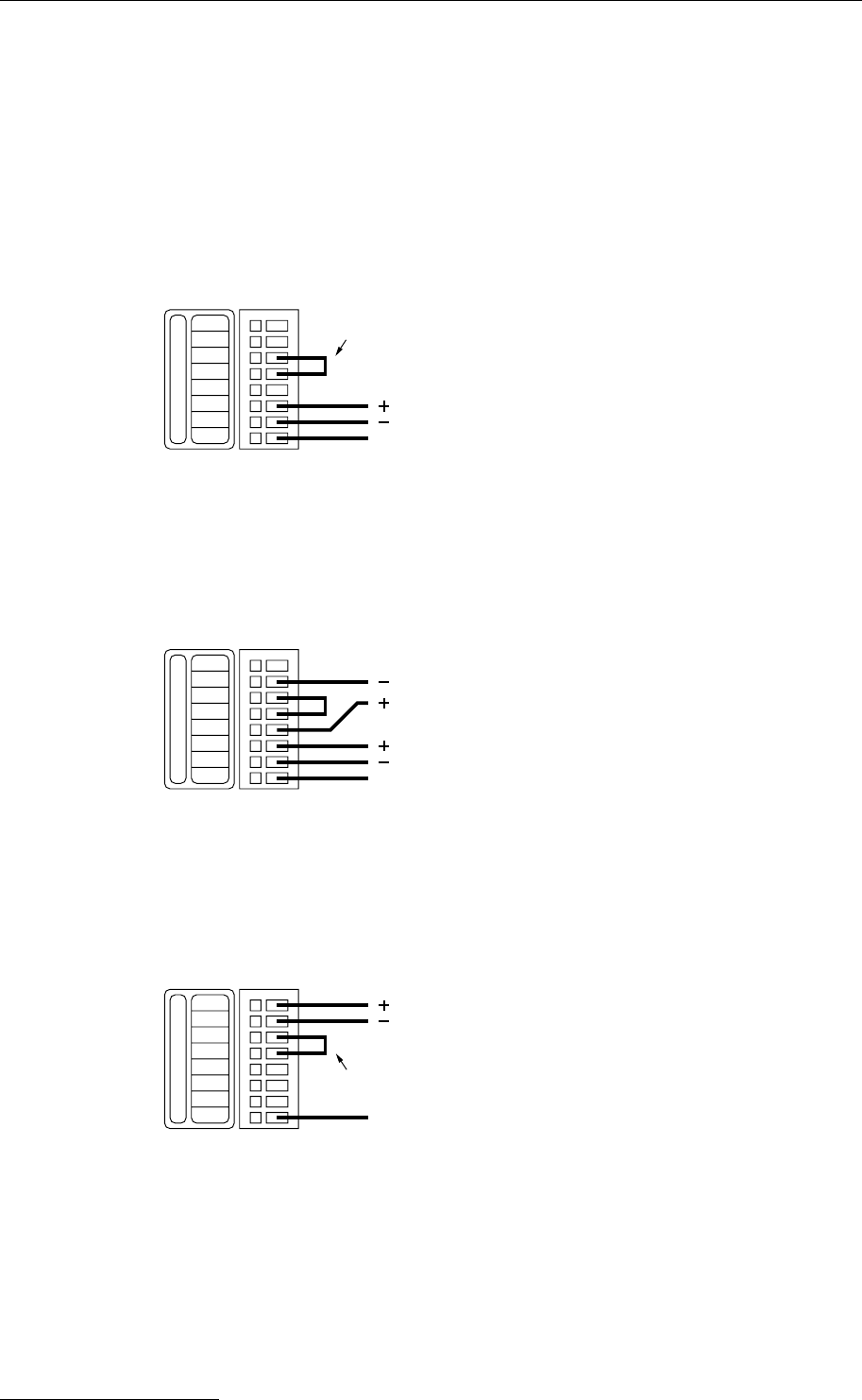
Fig. 7 illustrates the connections available at the POWER connector.
EXTPS
GND
Power
Pd1
Pd0
BATT
Shield
GND
SOLAR
Start−Jumper
to Solar Panel
to Solar Panel
Enclosure Connection
Fig. 7: A740 POWER Connector (Top View)
You might want to use the POWER connector with something other than the
standard configuration. For example, if you want to connect an external battery to
the RTU, disconnect the internal battery and use the configuration shown in Fig. 8.
EXTPS
GND
Power
Pd1
Pd0
BATT
Shield
GND
SOLAR to Solar Panel
to Solar Panel
same type as supplied by Adcon
to external Battery
Enclosure Connection
Fig. 8: A740 Connection with External Battery
If you want to use the internal battery with a different power supply (charger) than
the solar panel provided, disconnect the solar panel and use the configuration
shown in Fig. 9.
EXTPS
GND
Power
Pd1
Pd0
BATT
Shield
GND
SOLAR Start−Jumper
ext. stabilized Power Supply
Enclosure Connection
12−24VDC, .6Amax.
Fig. 9: A740 Connection with External Power Supply
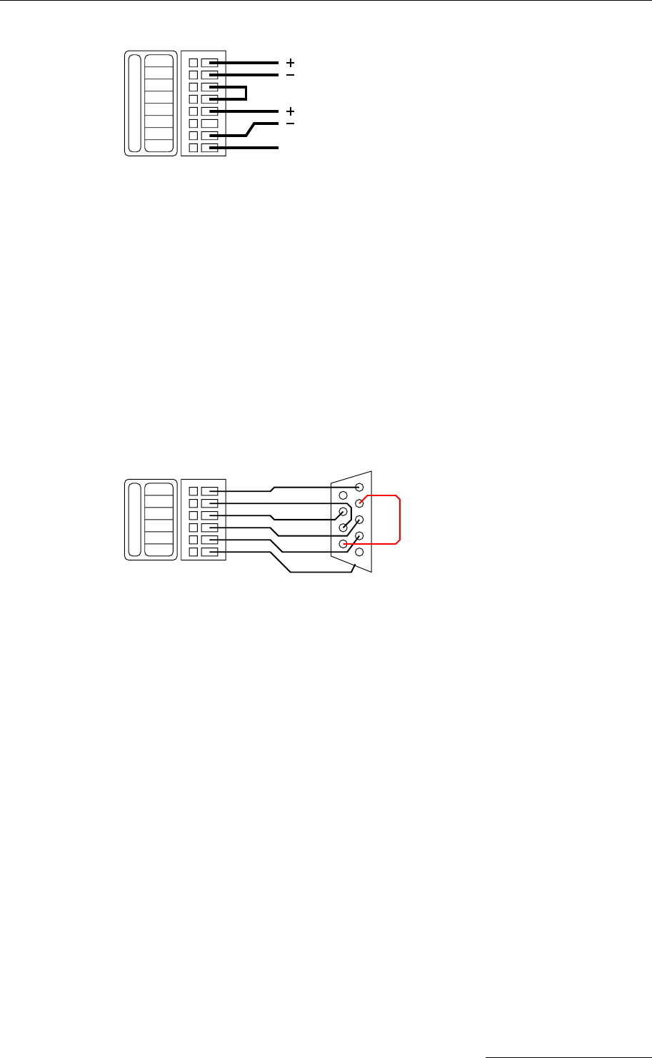
And if you want to use an external battery with a different power source (charger)
than the solar panel provided, disconnect the internal battery and solar panel and
use the configuration shown in Fig. 10.
20
The RTU connectors
EXTPS
GND
Power
Pd1
Pd0
BATT
Shield
GND
SOLAR
ext. stabilized Power Supply
to external Battery
Enclosure Connection
same type as supplied by Adcon
12−24VDC, .6Amax.
Fig. 10: A740 Connection with External Battery and Power Supply
Note: The cable used for the external power supply may not exceed 3 meters.
3.1.2 Serial Interface – RS-232
The serial interface on the A740 has the following characteristics:
• RS-232 data format
• V24 signal voltage levels
• DTE wiring (RxD, CTS are input and TxD, RTS are output)
To connect the A740 to a PC, use the following cable:
GND
CTS
RTS
RXD
RS−232
TXD
Shield 1 DCD
2 RXD
3 TXD
4 DTR
5 GND
Enclosure Connection
RI 9
CTS 8
RTS 7
DSR 6
9−pin female
SUB−D connector
using a short wire
connect pins 4 and 6
Fig. 11: Serial interface cable to connect a PC to an A740
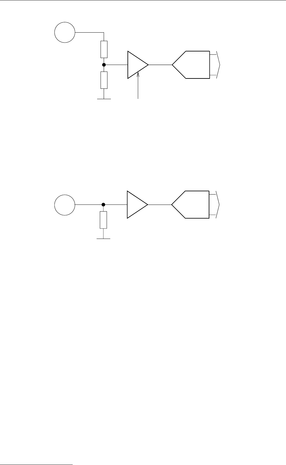
3.1.3 Analog Inputs
The analog inputs can be used to measure a voltage or a current signal.
Depending on the configuration, the input signal range can be 0-1V, 0-2.5V, 0-5V
and 0-10V. Each input can be configured to one of the available input ranges.
To use the inputs with voltage signals, the Jumpers J7-J14 must be set to position
1-2 and 3-4.
21
Performing Advanced Functions
AMP.
GAIN 0−1V
0−2.5V
0−5V
0−10V
ADC
to uC
AINn
J7−J14=1−2&3−4
Fig. 12: Analog inputs in voltage mode
To use the inputs with current signals (0-20mA or 4-20mA) the Jumpers J7-J14
must be set to position 1-3 AND 2-4.
AMP. ADC to uC
50R
Current Input Type, 0−20mA | 4−20mA
AINn
Fig. 13: Analog inputs in current mode
3.1.4 Analog Output
Depending on the RTU's configuration, this type of output can supply a voltage
between 0 and 2.5V. With increasing sink-current, the accuracy of the generated
voltage will decrease, since the internal resistance of the output is approximately
100 Ohm.
22

The RTU connectors
f
rom uC 10−Bit DAC Amp.
AOUT
Stage 1
Fig. 14: Analog output
3.1.5 Digital Inputs
The digital inputs can be configured in several ways: First, the type of the
connected input has to be selected (Stage 1):
• When using the A740 in conjunction with a rain gauge, the “pull up” option
has to be jumpered.
• Signals in the range of 3 - 30V can be connected directly to the inputs
using the “pull down” option.
Then, the type of debouncing has to be selected (Stage 2):
• A debounce circuitry can/must be used, when the inputs will be connected
to a pulse counter and a mechanical contact (e.g. reed-contact of an Adcon
rain gauge) is used. The upper frequency limit is approximately 50 Hz.
• For signals faster than 50 Hz the debounce circuitry must be bypassed.
The maximum frequency is about 10 kHz. Fast counter or frequency input
works with clean signals only!
At last, the usage of the input signal has to be selected (Stage 3):
• Digital Input
• Counter (resolution is 16 bit)
• Frequency measurement (resolution is 16 bit). The gate time for frequency
measurement can be configured from 1 to 60 seconds (note: since the
resolution is 16 bit, the product of maximum frequency and gate time must
not exceed 65535 or the device will calculate incorrect measurement
values!).
23

Performing Advanced Functions
DINn
DINn
Stage 1 Stage 2
GND
Vcc
J3|4|5|6=3−4
"With Pull UP"
J3|4|5|6=1−2
"With Pull Down"
LPF fg~50Hz
Stage 3
Mode=Static|Counter/Freq.
to u
C
"H"
from TIMEBA
SE
Mode=Counter|Freq.
GATE
16Bit Counter
LPF=ON/OFF
to uC
Fig. 15: Digital inputs
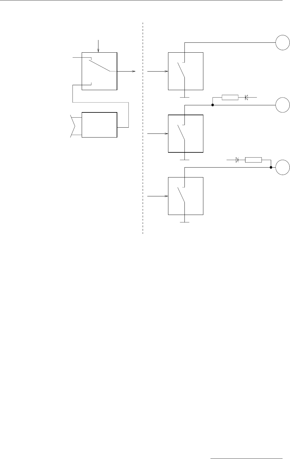
3.1.6 Digital Outputs
The Digital Outputs of the A740 are protected low-side switches (4 channels). An
optional pull-up-resistor can be connected to VExtps or Vbatt. The resistance value is
1KOhm.
When J2 is in position 3-4 and operating with external power supply (12-24V) one
output can source a maximum of 12mA (at 12V) to 24mA (at 24V) according to the
external power supply voltage. In this configuration a small LED or
OPTOCOUPLER can be attached directly to the output of the A740.
When J2 is in position 2-4 a maximum of 5.5mA (at 5.5V) to 7.5mA (at 7.5V) can
be sourced, depending on the battery voltage. Keep in mind that the current comes
from the battery!
In the configuration without a pull-up (J2 is in position 1-2) the load must be
connected to a voltage <= 30V.
Do not sink more than 30mA continuous current!
24
The RTU’s Jumpers
TYPE
PWM−Block
Static HI/LO
or MF/MV
PWM
f
rom uC
f
rom uC
Stage 1 Stage 2
from int.
Battery
J2=3−4
J2=1−2 or 1−3
J2=2−4
from external PS
"No Pullup"
"With Pullup, ext. PS"
"With Pullup, int. Batt"
1K
1K
DOUT
n
DOUT
n
DOUT
n
Fig. 16: Digital outputs
3.1.7 SDI-12 Interface
The SDI-12 interface is not available in the current A740 software version.
3.1.8 Expansion Port
The expansion port supports up to 3 addPORT expansion boxes. These have to be
connected using the expansion port cables supplied with the expansion box. The
position of the expansion box in this daisy chain determines its ID. The first
expansion box gets ID 1, the third expansion box in the chain gets ID 3.
Note: The cable used for the expansion port must not exceed 0.3 meters!
3.2 The RTU’s Jumpers
See below for the position of the various jumpers on the A740-board. Jumper J1 is
used for putting the system into programming mode for firmware updates and for
resetting the CPU. Jumper J2 is used to select the voltage source for the digital
outputs (see Section 3.1.6.). Jumpers J3 (DIGIN4) to J6 (DIGIN1) are used for
25

Performing Advanced Functions
selecting pull-up or pull-down for the digital inputs. Jumpers J7 (AIN1) to J10
(AIN4) and J11 (AIN8) to J14 (AIN5) determine whether the analog inputs are used
as voltage or as current inputs (see Section 3.1.3).
4
3
2
1
J2
1
2
3
4
1
2
3
4
1
2
3
4
1
2
3
4
J11 J12 J13 J14
1
2
3
4
1
2
3
4
1
2
3
4
1
2
3
4
J4 J3J6 J5
4
3
2
1
4
3
2
1
4
3
2
1
4
3
2
1
J10 J9 J8 J7
2
4
1
3
J1
Fig. 17: Digital outputs
3.3 Checking the RTU’s Status
The A740 features an integrated button and an LED, which can be used for
checking the RTUs battery status. This button can be used to start the RTU, if in
off state, by pushing the button for at least 1 second.
If the RTU is already operating pushing the button for less than a second will make
the LED flash in half-second intervals if the battery voltage is higher than 5.5V. If
the batteries voltage is in the range from 5.0V to 5.5V, the blinking occurs in
two-second intervals.
Holding down the button for at least two seconds until four blinks of 1/8th of a
second each are signaled by the RTU will trigger a connectivity test as soon as the
button is released (fur further information see section 5).
If you keep the button down for another 2 seconds, until four more blinks of 1/8th of
a second are flashed, the RTU will shut off as soon as the button is released. You
can recognize this when the RTU stops blinking in the 1/8th second intervals.
Note: The RTU cannot be turned off if external power is fed into the RTU via the power
connectors EXTPS input. In this case the RTU will flash the LED for one minute
and try to turn itself off. Removing the power connector will then cause the RTU to
shut down.
3.4 Communicating with the RTU
You can use a Windows HyperTerminal window to connect to the addNODE RTU.
After you have installed the system, follow these steps to configure the device and
set the default parameters:
26

Serial communication protocol
Note: To configure the A740 RTU, you must have a special adapter cable (available from
Adcon) and plug it into the POWER connector.
1. Open a HyperTerminal window.
2. Select the appropriate serial port and click OK.
3. Configure your terminal as follows:
• 19200 baud
• 1 stop bit
• 8 data bits
• No parity
• No protocol (neither hardware nor software)
4. Select OK to open the terminal window.
5. Press Enter to generate a response in the window.
3.5 Serial communication protocol
This protocol is based on a master sending commands and a node answering; the
whole communication is conducted in plain ASCII, as strings. When exchanging
numbers, they are represented in decimal format. All commands are terminated
with a CR/LF combination. All responses (answers) are terminated with the #
character.
3.5.1 General format of a command
The commands have the following format:
[ID] Command Param1 Param2 ... ParamN
• ID (optional) is the destination device. If you include an ID as part of a
command, the node checks whether ID=ownID. If it does, the node
executes the command on itself. If the ID is not the node’s ID, the node
executes the command on a remote device, if such an ID exists. If the ID is
missing, this implies that the command is addressed locally.
Note: Not all the commands can be relayed remotely.
• Command is the command proper, which can be composed of a variable
string of characters (for example, INFO). Each node can implement a set of
commands depending on the functionality of the node itself. However, as a
minimum requirement, a node recognizes the CMDS command, which
returns a list with the commands recognized by the node.
• Param1 Param2 ... ParamN represent the parameters, which are
command dependent. If you type no parameters when you issue a
command, it is the equivalent of querying for information (the GET version
of a command). If you type parameters, you are issuing the SET version of
a command and are setting the command to the parameters you typed.
3.5.2 General format of an answer
The answers have the following format:
27

Performing Advanced Functions
ID Command Result1 Result2 ... ResultN ErrResult #
• ID is the answering device. If a command was further routed, it is the ID of
the end device. The answer must always contain the ID on return.
• Command is the string representing the original command. It is supplied so
that a master can distinguish between the answers it is waiting for, and out-
of-band notifications (which may come, for example, over the radio port of
a node). As with the ID, the command name must be always supplied.
• Result1 Result2 ... ResultN are the result values returned by the
remote node. If the ErrResult is not zero, all other possible characters
and/or strings until the end of the line may be ignored.
• ErrResult shows whether the command was successfully executed. If
this value is 0, the command was successfully executed. If this value is
other than 0, the command failed. The number may further indicate the
error type. (See also “Returned errors list” on page 49.)
The answer string may contain any number of spaces or CR/LF characters
between its components; however, after the terminator (#) no other characters are
allowed.
3.5.3 Commands Accepted by the A740 addNODE
Following is a list of available commands.
Note: You can type uppercase or lowercase characters because the commands are not
case sensitive.
CMDS
DESCRIPTION Returns a list of supported commands.
PARAMETERS None.
REMARKS GET only.
RETURNS A list of strings separated by spaces.
REMOTE No.
EXAMPLE #CMDS
53 CMDS B BLST CALC CMDS COMP COND DATA DATASDI FDEV FREQ ID
INFO IO LC MSTR NPND OC OPMODE PC PMP ROUTE RSSI RX SWITCH
TIME TX TYPE VER XCONF XDATA XIMME 0
#
TIME
DESCRIPTION Sets/returns the real time clock.
PARAMETERS The actual time, or none in the GET version.
RETURNS The actual time as dd/mm/yyyy hh:mm:ss.
REMARKS GET/SET.
REMOTE No.
EXAMPLES TIME 12/12/1999 22:10:10
193 TIME 0
#
28

Serial communication protocol
TIME
193 TIME 12/12/1998 22:10:10 0
#
FREQ
DESCRIPTION Sets/returns the operating frequency.
PARAMETERS The operating frequency and step (Hz), or none in the GET version.
RETURNS The actual frequency and step, in Hz.
REMARKS GET/SET.
REMOTE Yes, SET only.
EXAMPLE FREQ 433925000 25000
193 FREQ 0
#
FREQ
193 FREQ 433925000 25000 0
#
RSSI
DESCRIPTION Sets/returns the Relative Signal Strength Indicator threshold at which an RF
receiver must wake up.
PARAMETERS The threshold value, which is an unsigned char. For the A740, it can take values
from 0 to 255; it is typically factory set to 42.
RETURNS The instant RSSI value and the programmed threshold.
REMARKS GET/SET.
REMOTE No.
EXAMPLE RSSI 42
193 RSSI 0
#
RSSI
193 RSSI 31 42 0
#
Note: The values of the RSSI threshold have no units, they are arbitrary. However, a
value of 240 corresponds approximately to the maximum value allowed in the
addVANTAGE software (that is, 8 µV).
ID
DESCRIPTION Sets/returns the RTU’s ID.
PARAMETERS The node ID.
RETURNS The node ID.
REMARKS GET/SET.
REMOTE Yes, SET only.
EXAMPLE ID 4557
193 ID 0
#
ID
4557 ID 4557 0
29

Performing Advanced Functions
#
6556 ID 7557
6556 ID 0
#
Note: The last example shows a case where a remote node was instructed to change its
own ID from 6556 to 7557. Even if it changed its ID, it answers with the old ID in
order to correctly finish the transaction.
TYPE
DESCRIPTION Returns the RTU’s type.
PARAMETERS None.
RETURNS The RTU’s type.
REMARKS GET only.
REMOTE No.
EXAMPLE TYPE
27330 TYPE A740 0
#
OPMODE
DESCRIPTION Returns the current operation mode.
PARAMETERS None.
RETURNS The current operation mode.
• 0: normal operation mode
• 1: (power save operation mode)
• 2: (exception operation mode)
REMARKS GET only.
REMOTE No.
EXAMPLE OPMODE
27330 OPMODE 1 0
#
PMP
DESCRIPTION Sets/returns the node’s Power Management Parameters (switches on/off the
battery charge).
PARAMETERS The lower (switch on) and the higher limit (switch off), both in volts x 10. Standard
Values are 65 (for 6.5 Volts) for switch on and 72 (for 7.2 Volts) for switch off (for a
standard 6.2 Volt NiCd battery). From these values, other thresholds are internally
computed. When the temperature drops below 10°C the upper threshold is
increased by 5 percent of its set value. Rises the temperature above 20°C the
upper threshold is reduced by 5 percent of its set value.
RETURNS The lower (switch on, a char) and the higher limit (switch off, a char), both in volts x
10.
REMARKS GET/SET.
REMOTE Yes, SET only.
EXAMPLE PMP 65 72
30

Serial communication protocol
193 PMP 0
#
PMP
193 PMP 65 72 0
#
FDEV
DESCRIPTION Called without parameter, FDEV works as in the A733 and just clears all the data
(and the index area). The sizes of data- and index area are NOT changed. If the
optional parameter is given, it specifies the percentage of flash memory used for
index data. The default percentage is 33% (selected on very first startup or when
FDEV 0 is called). Additionally internal checks are made for the given percentage
and if it is too large or too small (depending on the Flash memory type) an error is
returned.
PARAMETERS None, or percentage of flash memory used for index area.
RETURNS The commands success or error code.
REMARKS GET/SET.
REMOTE Yes. But only the version without parameters.
EXAMPLE FDEV
53 FDEV 0
#
FDEV 50
53 FDEV 0
#
INFO
DESCRIPTION Returns various status information.
PARAMETERS None.
RETURNS If no parameters are given, then INFO returns a list of a device’s internal variables:
ID INFO rf_in rf_out date time ver clk stack cop batt temp
days_uptime hr:min_uptime rssi pmp_low pmp_high type slot samples po
err_level
#
The formats for the above parameters are as follows:
• rf_in and rf_out as a decimal (unsigned char)
• date as dd/mm/yyyy
• time as hh:mm:ss
• ver as x.x
• clk, stack and cop as decimal (unsigned char); they represent internal
housekeeping parameters: the A740 uses cop to number watchdog
occurrences, clk and stack are currently undefined
• batt as battery level using the standard voltage conversion equation (0 is
0 volts, 255 is 20 volts)
• temp as internal temperature in the A740 housing, which is device
dependent. The precision of the sensing element is low (±2°C), but it is
31

Performing Advanced Functions
sufficient for battery power management (charge/discharge). To compute
the actual value (in °C), the following equation must be used:
Temp = internalTemp * 400
255 - 68
• days_uptime in days; together with hr:min_uptime it represents the
amount of time the device is up without a reset or watchdog
• hr:min_uptime in hours:minutes format
• rssi as decimal (unsigned chars); it is the programmed value with the RSSI
command
• pmp_low and pmp_high are the programmed values with the PMP
command
• type is used to represent the device type; following types are assigned
currently:
0 for A730MD
1 for A720
2 for A730SD
3 for A720B
4 for A733
5 for A723
6 for A440
7 for A733GSM
8 for A731
9 for A732
10 for A740
• slot and samples are currently unused
• po is the power output of the device during the last frame sent; this value is
relative (a value of 20 means approx. 50 mW while a value of 175 means
approx. 500 mW)
• err_level is the error value; 0 means no error
REMARKS GET only.
REMOTE Yes, GET only, and only the version without parameters. The A740 can issue the
command both remotely and locally.
EXAMPLE INFO
193 INFO 255 0 18/4/1999 21:5:11 1.0 0 0 0 91 72 40 1:46 58
65 72 0 0 15 0
#
RX
DESCRIPTION Switches the unit to permanent receive mode (for tuning purposes).
PARAMETERS None.
RETURNS Nothing.
REMARKS The system stops, and exits the command only when a key is pressed. This
command returns no message.
32

Serial communication protocol
REMOTE No.
EXAMPLE RX
193 RX 0
#
TX
DESCRIPTION Switches the unit to transmit mode (for tuning purposes).
PARAMETERS None (sends an unmodulated carrier), 1 (sends a 1 kHz modulated carrier), 0
(sends a 2 kHz modulated carrier) or 5 (sends a mixed 1 + 2 kHz modulated
carrier).
RETURNS Nothing.
REMARKS The system stops, and exits the command only when a key is pressed. This
command returns no message.
REMOTE No.
EXAMPLE TX
193 TX 0
#
TX 1
193 TX 0
#
TX 5
193 TX 0
#
B
DESCRIPTION Sends a broadcast frame.
PARAMETERS None.
RETURNS A data block.
REMARKS After the device sends the broadcast frame, it will listen for answers. All valid
answers will be listed with their IDs.
REMOTE Yes. A device getting this frame would have to wait for a random time (2 to 10
seconds) before performing the actual broadcast; if no terminal is active, then no
results will be listed. A list of heard stations with their RF levels will be updated in
the memory and available whenever the BLST command is issued.
EXAMPLE B
193 B 0
#234 BA 0
#7851 BA 0
BLST
DESCRIPTION Lists the stations heard after the last broadcast command was issued.
PARAMETERS None.
RETURNS The date and time when the broadcast was performed, the number of stations
heard and a list with the heard stations’ ID and their respective RF levels
(incoming/outgoing pairs, i.e., how the foreign RTU was received and how the
foreign RTU received the broadcasted radio packed).
REMARKS GET only.
REMOTE Yes. The remote version will list only the first 9 stations heard.
33

Performing Advanced Functions
EXAMPLE BLST
193 BLST 10/12/1999 12:15:04 4
2008 150 185
2003 177 210
6883 168 180
4027 220 255
#
VER
DESCRIPTION Requests the firmware version of the device.
PARAMETERS None.
RETURNS The current version.
REMARKS GET only.
REMOTE No.
EXAMPLE VER
193 VER 1.3 0
#
Note: This command is provided only for compatibility with older units. The host software
may use this command to identify the unit it is communicating with. After detecting
that the device supports this protocol, the INFO command must be used for further
details, if available.
MSTR
DESCRIPTION: This command shows or sets the master receiver of the RTU, which is used for
delivery of notifications.
PARAMETERS: MSTR [ 0 | [ <hop_id1> [ ... [ <hop_id8> ] ] ] <destination_id> ]
None, "0", of the route to the master receiver (including the master receivers id as
last item in the list)
REMARKS: GET/SET.
RETURNS: The commands success or error code, or the route to the current master receiver.
REMOTE: Yes, via XCONF. Particularly "MSTR 0" is designed for the remote case.
EXAMPLES: MSTR
58 MSTR 58 42 0
#
123 XCONF MSTR 0
123 XCONF MSTR 0
#
ROUTE
DESCRIPTION: This command shows or sets the route to remote station. It is available on all RTUs
and A440 devices.
PARAMETERS: ROUTE [ <destination_id> [ <up_to_eight_relay_ids> ] ]
None, or a route (with destination) containing up to eight intermediaries. When just
the <destination_id> is given, then the route for this device is deleted. Depending
on the size of the devices routing table, routes might have to be deleted before
new routes are inserted. Currently the A740 can only hold one route at a time.
34

Serial communication protocol
REMARKS: GET/SET.
RETURNS: The commands success or error code. or the route table.
REMOTE: No.
EXAMPLES: ROUTE 42
58 ROUTE 0
#
ROUTE 42 1 2 3 4 5
58 ROUTE 0
#
ROUTE
42 1 2 3 4 5 0
#
XCONF
DESCRIPTION: This command transmits command strings for commands, which are suited for this
mode of operation, to the targeted RTUs. Allowed commands are: CALC, COMP,
COND, LC, MSTR, NPND, OC, OPMODE, PC, ROUTE, SWITCH, VER.
PARAMETERS: XCONF <command-string>
The command string with all parameters of the command to be transmitted to the
remote device.
REMARKS: The remote version sends a corresponding radio request, the local version acts a
NOP.
RETURNS: The reply string and the commands success or error code is returned.
REMOTE: Yes, but remote only.
EXAMPLES: 53 XCONF COND 0
53 XCONF COND 0 0 0
#
XDATA
DESCRIPTION: This command requests data for a list of logical channels for given timestamps.
PARAMETERS: XDATA <Tsync> <flags> <Tlast> <last channel> <max values> <nr
of channels> <channels ...> [ <max packet size> [ <Tto> ] ]
<Tsync>: — Timestamp in UTC to synchronise the RTU. When zero, then no time
synchronisation is requested.
<flags>: — These can be a combination of all defined request and reply flags:
• QUERY_FLAGS_MANDATORY (0x01): Request the RTU to honor all
flags, or if it is not capable of honoring all given flags, to return an error. If
this flag is not set, in its reply the RTU will clear capability flags for abilities
it does not possess.
• QUERY_FLAGS_NOSYSTEMTIME (0x02): This flag is a reply flag of the
RTU to indicate that the system time needs to be set.
• QUERY_FLAGS_NOTIFYPENDING (0x04): This flag is a reply flag of the
RTU and indicates a pending notification.
• QUERY_FLAGS_NEWESTVALUES (0x08): Request the RTU to only send
the newest value for each requested logical channel. In order to retrieve
the RTUs capabilities, sets all (known) flags except for the
QUERY_FLAGS_MANDATORY flag and sets <Tlast> and <Tto> to the
35

Performing Advanced Functions
same value (or the number of requested values to zero). Then the RTU will
reply with only those flags set, which it can honor.
<Tlast> <last channel>: — Timestamp in UTC of the last received data and
last channel we received data for.
<max values>: — The maximum number of values requested.
<nr of channels>: — The number of channel number given in the following
field(s), 0 to return all available channels.
<channels ...>: — The number (i.e., identifier) of the logical channels we want
to retrieve data from.
<max packet size>: — Optional, 255 when omitted.
<Tto>: — Optional. The timestamp up to (and including) which data is requested.
If omitted, assume latest possible timestamp.
Data will be retrieved until one of the following limits is reached, be it availability of
data values, the maximal number of values requested, or the maximum radio
packet size which is reached.
REMARKS: This is a data retrieval command, local as well as remote.
RETURNS: The requested data if available is returned in the following format:
<rfin>: The RF value as the frame was received by the first receiving device. It is
an integer value in the range of 0 to 255.
<rfout>: The RF value as the request frame was received by the replying RTU.
<flags>: The capabilities and status of the RTU (see parameters).
The next set of fields is only available if there is any data received at all:
<last-saved-time_t>: The save timestamp of the first data value(s).
<number of values>: The actual number of values returned for this save-
timestamp of the reply.
<measured-values>+: At least one data record saved at the given <last-
saved-time_t>, which is comprised of:
<channel-no>: Number of logical channel this data belongs to.
<status>: Status and type of data:
• DATA_NOT_VALID 0x0fU
• DATA_NOT_AVAILABLE 0x07U
• DATA_VALID_BIT_0 0x00U
• DATA_VALID_BIT_1 0x01U
• DATA_VALID_BYTE 0x02U
• DATA_VALID_WORD16 0x03U
• DATA_VALID_WORD32 0x04U
• DATA_VALID_FLOAT 0x05U
• /* DATA_VALID_BYTEFIELD 0x06U */
• DATA_PARTIAL_BIT_0 0x08U
36

Serial communication protocol
• DATA_PARTIAL_BIT_1 0x09U
• DATA_PARTIAL_BYTE 0x0aU
• DATA_PARTIAL_WORD16 0x0bU
• DATA_PARTIAL_WORD32 0x0cU
• DATA_PARTIAL_FLOAT 0x0dU
• /* DATA_PARTIAL_BYTEFIELD 0x0eU */
<value>: Actual value for integer and float values when valid or partial.
<t-measurement>: optional offset to save time, when then value was
actually measured.
<interval>: optional interval time of saving values.
Following values start with a time offset relative to the immediately preceding point
in time (even when given as offset):
<t-diff-to-previous-record>: Time offset to previous save time. Thus a
software must add up the <last-saved-time_t> and all the intermediate <t-diff-to-
previous-record> offsets in order to calculate the correct point in time when the
following values were saved.
<number of values>: Same as above.
<m-values>+: Same as above.
This data format was designed in order to optimize the available space. With
transmission speed being quite low, data space is highly valuable in radio frames.
REMOTE: Yes.
EXAMPLES: XDATA 0 0 1092746115 0 255 0
59 XDATA 0 0 0x0 0x4121fbb0 6 0 0xf5 4.965209 2 0xf5 2.268247
9 0xf5 14.90196 11 0xf5 0 13 0xf5 -97.79932 14 0xf5 14.90196
10 1 12 0xf5 941
5 2 1 0xf5 2.298866 6 0xf5 1883
15 2 3 0xf5 2.494401 5 0xf5 8173
15 1 7 0xf5 6886
15 1 0 0xf5 4.949338
15 2 1 0xf5 2.293983 6 0xf5 1879
45 5 0 0xf5 4.963989 2 0xf5 2.267637 9 0xf5 14.90196 11 0xf5
0 14 0xf5 14.90196
10 1 12 0xf5 940
5 2 1 0xf5 2.298866 6 0xf5 1883
15 2 3 0xf5 2.494401 5 0xf5 8173
15 1 7 0xf5 6886
15 2 0 0xf5 4.961547 13 0xf5 -68.45947
15 2 1 0xf5 2.296425 6 0xf5 1881
45 6 0 0xf5 4.948117 2 0xf5 2.259091 8 0xf5 6.352942 9 0xf5
15.05882 10 0xf5 26.11764 11 0xf5 0
0
#
XIMME
DESCRIPTION: This command delivers immediate data either from all configured physical
channels in converted (engineering) or raw values, or all raw ADC values.
PARAMETERS: XIMME <samplemode> ...
37

Performing Advanced Functions
XIMME { 0 | 1 } [ <max packet size> [ <pchan_nr> ... ] ]
XIMME 2 <max packet size> <adc_nr> <range>
<samplemode>: This specifies which values and how they are taken:
• 0 .. converted data from configured physical channels
• 1 .. raw data from configured physical channels
• 2 .. raw data from all ADC channels of a given ADC (on motherboard of
expansion board)
<max packet size>: The maximum packet size for the reply. When 0, then the
maximum number (255) is assumed.
<pchan_nr>: A list of physical channel numbers used for filtering in sample
modes 0 and 1. If no list is given, all configured channels are sampled and printed.
The following parameters are used for samplemode 2 only:
<adc_nr>: The address of the ADC, 0 for the ADC on the A740 motherboard, 1
to 3 for the respective expansion boards' ADCs.
<range>: The range specifies the measurement range of the ADC and can be
selected from:
• 0: 0..1V
• 1: 0..2.5V
• 2: 0..5V
• 3: 0..10V
REMARKS: This command can also be used for calculating compensation values for the ADCs.
Actually the <max packet size> is ignored for XIMME 2.
RETURNS: XIMME 0 and XIMME one return the values of the requested or all physical
channels either converted (samplemode 0) or raw (samplemode 1) as the tupple
<physical channel no>, <type>, and <value> (see also XDATA). XIMME 2
returns the raw values of the selected ADC (<adc_nr>) with the selected
measurement <range>.
REMOTE: Yes.
EXAMPLES: XIMME 2 0 0 3
59 XIMME 0 4262 915 1949 1727 1 1 0 -1 0
#
59 XIMME 0 0xf5 5.198392 1 0xf5 2.235382 2 0xf5 2.374152 3
0xf5 2.493485
4 0xff 5 0xf5 8169 6 0xf5 1830 7 0xf5 6907
8 0xf5 6.666667 9 0xf5 14.90196 10 0xf5 29.25489 11 0xf5 0
12 0xf5 0 13 0xf5 915 14 0xf5 -61.12451 15 0xf5 77.64618
0
#
59 XIMME 0 0xf5 4256 1 0xf5 1830 2 0xf5 7776 3 0xf5 8172
4 0xf5 1726 5 0xf5 8170 6 0xf5 1831 7 0xf5 6906
8 0xf5 85 9 0xf5 95 10 0xf5 62 11 0xf5 914
12 0xf5 914 13 0xf5 915 14 0xf5 536 15 0xf5 1831
0
#
38

Serial communication protocol
3.5.3.1 Data Acquisition, Outputs and Operation Modes
Data acquisition is comprised of three main parts:
1. definition of physical channels ,
2. definition of computations,
3. definition of logical channels.
First the sensor type and conversion to engineering units are configured into the so
called physical channel (see PC command). Then a computation needs to be
defined that will take the data from the physical channel, process the data and,
assigns it to a logical channel (see CALC command). The logical channel then
contains configurations about actions to be performed under certain conditions
(see LC command):
1. saving the result,
2. generating a notification,
3. switching an output,
4. triggering an operation mode change.
The conditions used for triggering actions have to be defined in the condition table
(see COND command)
In order to be able to switch an output, a so called output channel has to be
configured (see the OC command). Such an output channel can either be switched
automatically (via logical channel) or manually (see SWITCH command).
The A740 addNODE provides three different operation modes, each of which can
be configured to best suit a certain set of parameters. The first operation mode
(also referred to as Normal Mode) is mode number 0 and is the initial operation
mode. Operation mode changes are initiated when data is transferred to a logical
channel (see LC command). Depending on the operation mode different data
acquisition rules can be set (e.g., different sampling intervals can be used, more or
less sensors than in normal mode can be sampled, etc.). For further information
see the <modemask> parameter which is described in more detail in section
3.5.3.2.
Operation modes 1 and 2 have no special meaning and are referred to by their
numbers only. These are at your disposition and allow you to specify different
sampling intervals and event handling (e.g., one of these modes could be used as
“power saving mode”, while the other one could be used as an emergency mode,
etc.)
3.5.3.2 Table commands
With the A740 devices a new class of commands, the table commands were
introduced. They share a common similar syntax, which is by far more flexible than
the syntax used for commands up to now. The general syntax for table commands
and its meaning are as follows:
• <command> list whole config
• <command> <nr> list config entry for given element
• <command> <nr>+ list next used id's config entry, beginning with <nr> (if
<nr> is used, return <nr>!)
• <command> ? return size of table and the number of used entries
39

Performing Advanced Functions
• <command> + ... use next free id-nr for the config entry and return the
id number
• <command> <nr> configure given element/entry
• <command> -<nr> delete given element/entry
Most of the table commands accept a parameter <modemask> which is a bitmask
and describes in which operation modes the specified descriptor will be active. The
A740 has three operation modes and it starts up with mode number zero.
Operation mode switches can be selected with the LC command (see below). The
modes are referred to as “normal mode”, “power save operation mode” or mode 1,
and “exception operation mode” or mode 2. Modes 1 and 2 can also be used with
other meanings, since these modes have no hardwired or special meanings. Also
note that “misery state”, which is activated when the battery voltage drops to 5.5V,
is different from the aforementioned operating modes which only affect the
operation of the data acquisition.
The commands which use this syntax are marked as such in the descriptions
remarks section.
CALC
DESCRIPTION: This command allows configuring the calculation functions used for data
acquisition. Needed values are: the modes, in which the entry is active, the interval
the calculations are carries out, a reference time the calculations (and data
acquisitions) are aligned to, the number of and the individual (physical) input
channels used, the number of and the individual (logical) output channels needed
and finally the parameters to the calculation, e.g. the number of values to build am
arithmetical mean value of.
PARAMETERS: CALC <canr> <modemask> <interval> <Tref> <flags> <function>
<nr_of_input_pcs> <pc> <mask for which outputs to use>
<nr_of_output_lcs> <lc> <nr_of_params> [ <param> ... ]
• <canr> — Calculation number, an integer value starting from 0.
• <modemask> — A bitmask which specifies the modes, in which the entry
is active.
• <interval> — The interval in second within which the calculation has to
deliver a complete value.
• <Tref> — A timestamp (a time_t) giving the starting time and
measurement time(s) for this calculation (reference point in time). A time
value in the future will start measurements at this point in time, provided all
the measurements can be taken in the remaining time.
• <flags> — 0 acts as a NOP, 1 specifies, that the interval info for this
calculation has to be saved, too.
• <function> — A number specifying the calculation function used here.
The meaning of the numbers is:
o 0 arithmetical average (1 param = nr_of_samples)
o 1 circular average (3 params, nr_of_samples, lowest value,
highest value)
o 2 minimum (1 param = nr_of_samples)
o 3 maximum (1 param = nr_of_samples)
40

Serial communication protocol
o 4 sum (1 param = nr_of_samples)
o 5 first value (1 param = nr_of_samples)
o 6 last value (1 param = nr_of_samples)
• <nr_of_input_pcs> — The number of input channels used for this
calculation.
• <pc> — The physical channel(s) (currently only 1, later on up to 3) used
as input(s).
• <mask for which outputs to use> — A bitmask denoting the
position in the list of logical channels used as outputs.
• <nr_of_output_lcs> — The number of output channels used for this
calculation.
• <lc> — The logical channel(s) (currently only 1, later on up to 3) used as
output(s).
• <nr_of_params> — The number of parameters given to this calculation.
• <param> — The parameters for this calculation.
REMARKS: This command belongs to the new class of table commands.
RETURNS: The commands error of success code, or the current configuration.
REMOTE: Yes, via XCONF.
EXAMPLES:
COMP
DESCRIPTION: This command sets one or lists (all or one) ADCs compensation information. The
<adc_nr> specifies:
• 0: ADC on A740 motherboard
• 1: ADC on 1st expansion box
• 2: ADC on 2nd expansion box
• 3: ADC on 3rd expansion box
The offset values are per analog input line, and the gain values are valid per gain,
but are the same for all input lines and are used as a factor as in the formula:
measured-value{line} * k{gain} / 8191 + d{line}
PARAMETERS: COMP lists all ADCs compensation values
COMP <adc_nr>[+] lists ADC <adc_nr>'s compensation values
COMP <adc_nr> <4 gain(k) values> <8 offset (d) values>
set ADC <adc_nr>'s compensation values
COMP ? returns number of ADCs (both for max and used)
REMARKS: This command belongs to the new class of table commands. But it cannot and
does not implement the full syntax (e.g. deletions)
RETURNS:
REMOTE: Yes, via XCONF.
EXAMPLES:
41

Performing Advanced Functions
COND
DESCRIPTION: This command allows specifying conditions and limits for those conditions, which
can be used by logical channels to trigger saving, notification, etc. Condition
number 0 is the default condition for the LC command and is thus per default set to
"never" (type 0) and must not be changed. Attempts to do so result in error number
5 (parameter error).
PARAMETERS: Depending on the condition type there is a varying number of parameters (see
above). The meaning of the condition <type> is:
• 0: never
• 1: always
• 2: upper limit (with hysteresis)
• 3: lower limit (with hysteresis)
• 4: within limits (with hysteresis)
• 5: outside limits (with hysteresis)
The parameters (if any) for the different condition types are always given in
ascending order.
COND <cnr> <type>
COND <cnr> 0|1
COND <cnr> 2|3 <limitlo> <limithi>
COND <cnr> 4|5 <lowerlimitlo> <lowerlimithi> <upperlimitlo>
<upperlimithi>
REMARKS: This command belongs to the new class of table commands.
RETURNS:
REMOTE: Yes, via XCONF.
EXAMPLES:
LC
DESCRIPTION: This command specifies which actions to take, when a result value calculated from
measurement value is available. Actions to take may be:
• 1: saving of a value
• 2: sending of a notification request to the master receiver
• 3: switching of an output channel (see also OC command)
• 4: operation mode change
In addition there are the *_flags parameters, which specify when to call the
condition and perform the action.
PARAMETERS: LC <lnr> <modemask> <lowerverifier> <upperverifier>
<save_cnr> <save_cnr_flags> [ <notification_cnr>
<notification_cnr_flags> [ {<switch_output_cnr>
<switch_output_cnr_flags> <onr> | 0 0 0} [ <modeswich_cnr>
<modeswitch_cnr_flags> <save_partial_data_0_1> <priority>
<new_mode> ] ] ]
<lnr> — Logical channel number
42

Serial communication protocol
<modemask> — See section 3.5.3.2
<lowerverifier> — Lowest value permitted (float value or - for no verifier)
<upperverifier> — Highest value permitted (float value or - for no verifier)
<save_cnr>,
<notification_cnr>,
<switch_output_cnr>,
<modeswich_cnr> — numbers of conditions to be used for various actions
<onr> — numbers of output channel to use
<save_cnr_flags>,
<notification_cnr_flags>,
<switch_output_cnr_flags>,
<modeswitch_cnr_flags> — The flags of the condition numbers define what
to assume if the logical channel's value is either not valid or not available. For now,
it is a bitmask with only one bit used (bit 0 for both not valid and not available), but
it could be expanded later.
This is how the condition is evaluated:
if LC result is valid or partial:
call the condition's eval function and use its return value,
else
here we do not call the condition's eval function, but:
if the flag is 0, assume the condition evaluates to false
if the flag is 1, assume the condition evaluates to true
<save_partial_data_0_1> — This flag determines if so called partial data
(not a fully calculated value due to missing samples) will be saved in a mode
switch
<priority> — Priority of this modeswitch (the logical channel with the highest
priority will be selected):
• 0: none (disabled)
• 1: lowest priority
• 255: highest priority
<new_mode> — The new operation mode, which should be entered when the
entry is selected:
• 0: normal operation mode
• 1: (power save operation mode)
• 2: (exception operation mode)
REMARKS: This command belongs to the new class of table commands.
RETURNS:
REMOTE: Yes, via XCONF.
EXAMPLES:
NPND
DESCRIPTION: This command list and clears pending notifications and displays the number of
pending notifications.
43

Performing Advanced Functions
PARAMETERS: None, a logical channel, a logical channel with timestamp.
NPND: — list all logical channels with pending notifications
NPND <nr> — lists the pending notification for the given logical channel
NPND <nr>+ — list the next logical channel with a pending notification
NPND ? — display the number of logical channel available and the number of
logical channels with pending notifications
NPND <nr> <timestamp> — clear given pending notification condition
REMARKS: This command belongs to the new class of table commands.
RETURNS: The commands success or error code, or the pending notification(s) as
"channelnumber timestamp" pairs.
REMOTE: Yes, via XCONF.
EXAMPLES: NPND
58 NPND
1 1092442875
5 1092442123 0
#
NPND 5 1092442123
58 NPND 0
#
OC
DESCRIPTION: This command configures output channels, which can be used for analog output or
digital switching operations, either manually or automatically (see also SWITCH
and LC command).
PARAMETERS: OC <onr> <modemask> <type> <address>
<onr> — Output channel number
<modemask> — See section 3.5.3.2
<type>: — The type specifies the hardware parameters for the output channel:
• 0 static hi/lo
• 1 PWM
• 2 analogue
<address>: — consists of [module.]port, where
• module: 1..3 for first to third expansion module
• port: port name as printed on the label on the box (DOUT1..DOUT4,
AOUT1 on base device, DOUT1..DOUT3 on expansion modules)
REMARKS: This command belongs to the new class of table commands.
RETURNS:
REMOTE: Yes, via XCONF.
EXAMPLES:
44

Serial communication protocol
PC
DESCRIPTION: This command configures the physical channels, which are the input stage of the
data acquisition system. The physical channel descriptors contain verifiers,
conversion parameters for converting measured values into engineering units and
the hardware parameters needed for the actual sampling of the data.
PARAMETERS: PC <pnr> <modemask> <lowerverifier> <upperverifier> <n>
<a(0)> <a(n)> <chantype> <address> <parameters>
<pnr> — Physical channel number
<modemask> — See section 3.5.3.2
<lowerverifier>: — Lowest allowed value (float value or - for no verifier)
<upperverifier>: — Highest allowed value (float value or - for no verifier)
<n>: — The number of parameters used for the conversion (the current maximum
is two). When <n> is zero, no conversion at all is done. When <n> is 1, then a
table based conversion is done. Thus the meanings of <n> are:
0: no conversion,
1: table conversion (<a(0)> specifies the number of the table to be used),
2: linear conversion.
<a(0)>, <a(1)>: — Floating point parameters for the conversion function,
where <a(0)> is an offset, while <a(1)> is the factor (k * x + d). For analog-
to-digital channels, these two values denote the lower and upper threshold for the
analog to digital conversion (default 30% and 70% of full scale). These parameters
are applied to the raw values of the sampled data (e.g. to analog values in the
range from 0 (or slightly less) to 8191). If <n> is 1, then the one parameter
(<a(0)>) is the number of the conversion table for the table based conversion.
Currently there are 3 of those tables:
0: Gypsum Block Sensor Table
1: Leaf Wetness Sensor Table
2: Watermark Soil Moisture Sensor Table
which can be used for the corresponding sensors.
Note: For table based conversions the verifiers are applied before the conversion takes
place (i.e., they are applied to the raw values).
<address>: — consists of [module.]port, where
• module: omitted for base device, 1..3 for first to third expansion module
• port: port name as indicated on the devices top (AIN1..AIN8 or DIN1..DIN4
on base device and AIN1..AIN8 on expansion boards)
<chantype>: — This parameter gives the type of the channel and also indicates
which parameters are needed:
• 0: Analog channel with parameters <range> <address> <spt>
The ADC gives values in the range from 0 to 8191 (0V or 0mA give 0, the
max. value of the selected range gives 8191, so 20mA give 8191, too).
Assume a level sensor, which delivers a signal from 0V to 2.5V and 0V (or
0) is a level of 1 meter and 2.5V (or 8191) is a level of 5 meter. Thus the
conversion formula is:
45

Performing Advanced Functions
meter = raw / 8191 * 4 + 1
so n=2, a(0)=1, a(1)=0.0004883408619.
More generalized: Be Smax the maximum value of the sensor in
engineering units and Smin be the minimum value of the sensor in
engineering units. Thus
a(0) = Smin
and
a(1) = (Smax - Smin) / 8191
Sensors with 0 to 20mA interface are to treat in the same way. For sensors
with 4 to 20mA interface the calculation has to be slightly changed
a(0) = (5 * Smin - Smax) / 4
and
a(1) = (Smax - Smin) * 5 / (8191 * 4)
o <range>:
0: 0 .. 1 V
1: 0 .. 2.5 V
2: 0 .. 5 V
3: 0 .. 10 V
4: 0 .. 20 mA
5: 4 .. 20 mA
6: analog to digital conversion (measurements are in the range
of 0 .. 10 Volt); for meaning of conversion parameters see
description of <a(0)>, <a(1)>.
o <spt>: — The sensor power time is given in 0.5 second steps (0
means no sensor power needed)
• 1: Digital channel:
o 0: Frequency measurement with parameters: <address>
<fast> <gatetime>
o 1: Pulsecounters with parameters: <address> <fast>
o 2: Hi/Lo with parameters: <address> <fast>
<fast>: 0: input is slow (filtered, 10Hz)
1: input is fast (not filtered, 10kHz)
<gatetime>: in seconds (1..60)
• 2: Internal sensors (raw values):
o 0: Voltage of internal battery volts = raw_value * 20 / 255.
(a(0)=1, a(1)=20/255)
o 1: Voltage of external power supply volts = raw_value * 40 / 255
(a(0)=1, a(1)=40/255)
o 2: Temperature celsius = raw_value * 400 / 255 - 68
(a(0)=-68, a(1)=400/255)
46

Serial communication protocol
o 3: Battery charging current milliamps = (511 - raw_value) * 1000 /
409
(a(0)=511*1000/409, a(1)=-1000/409)
o 4: Battery charger (solar panel) on/off
o 5: Battery charged by external power on/off
Note: Internal sensors are currently sampled independently from external sensors every
five minutes only. When reading values from internal sensors, only the cached
values from the last measurements are read.
• 3: SDI is not yet implemented.
REMARKS: This command belongs to the new class of table commands.
RETURNS:
REMOTE: Yes, via XCONF.
EXAMPLES:
SWITCH
DESCRIPTION: Manually switch output channels.
PARAMETERS: SWITCH <onr> <type> <params> ...
<onr> — Output channel number
<modemask> — See section 3.5.3.2
The <type> parameter is the same as in the OC command: The parameters
(<params>) for the output channel types are:
• SWITCH <onr> 0 0 0 (static off)
• SWITCH <onr> 0 0 1 (static on)
• SWITCH <onr> 0 1 <low_t> <hi_t> (first lo-pulse for low_t secs,
then hi-pulse for hi_t secs)
• SWITCH <onr> 0 2 <hi_t> <low_t> (first hi-pulse for hi_t secs,
then low pulse for low_t secs)
• SWITCH <onr> 0 3 <low_t> <hi_t> (first lo-pulse for low_t secs,
then hi-pulse for hi_t secs, repeating)
• SWITCH <onr> 0 4 <hi_t> <low_t> (first hi-pulse for hi_t secs,
then low pulse for low_t secs, repeating)
• SWITCH <onr> 1 <percentage> <frequency>
<percentage>: 0..100, <frequency>: 1..16384
• SWITCH <onr> 2 <percentage> <percentage>: 0 .. 100
On conflicts between a switch request and output channel settings, the output
channel changes appropriately (if the channel is already defined, else return an
error).
REMARKS: This command belongs to the new class of table commands.
RETURNS:
REMOTE: Yes, via XCONF.
EXAMPLES:
47

Performing Advanced Functions
3.5.3.3 Commands for status display and diagnosing
CST
DESCRIPTION: on all RTUs, clear internal statistics counters
PARAMETERS: None
STAT
DESCRIPTION: on all RTUs, print all (or given task numbers) statistics counters
PARAMETERS: STAT [<tasknr>]
ESTAT
DESCRIPTION: on all RTUs, print nonvolatile storage statistics, either in short form (no parameter
given) or in a more verbose form (parameter 1 given)
PARAMETERS: ESTAT [ 1 ]
DUMP
DESCRIPTION: dump starting from <startaddr> to <endaddr>.
PARAMETERS: <startaddr> [<endaddr>]: If <endaddr> is omitted assume <startaddr>
+ 0xff (may be RAM, Data Flash; Program Flash only for development versions)
PMSC
DESCRIPTION: check or set/unset promiscuous mode on radio interface (very useful in
combination with VERB)
PARAMETERS: [ <0_or_1> ]
VERB
DESCRIPTION: check or set verbosity level.
PARAMETERS: VERB [ <level> ]: 0 means quiet.
PS
DESCRIPTION: show process status of all CMX tasks (including CMX timer task, i.e. slot 0) or only
for the given ids task.
PARAMETERS: PS [ <taskid> ]
3.5.4 Notifications
Notifications are frames sent asynchronously by devices that are otherwise slaves.
Before a device can issue a notification, the notification must first be enabled,
which is done by setting the notification condition for a logical channel. If the given
notification condition occurs, the device will try to send the notification to the device
configured using the MSTR command.
Note: To avoid collisions, the device will wait a random time (up to 10 seconds) before
sending the notification frame.
If an end device is not able to send a notification due to radio propagation or other
kind of communication problems, it will not send the notification again, but return
48

Serial communication protocol
the notification pending query flag in subsequent answers to an XDATA command.
It is the task of the master to use a reasonably short polling interval and to check
for presence of this flag in the XDATA result frame.
After receiving a notification frame, it is the task of the host to issure the
appropriate NPND commands to see which device has a notification pending and
to clear the pending notifications on both the A440 wireless modem and the A740
device.
3.5.5 Returned errors list
Following are error messages you might get.
Command line interpreter
1 — nonexistent command
2 — command line buffer overflow (input line too long)
3 — internal error
4 — reserved
5 — missing or false parameters in command
6 — operation not implemented
7 — remote version not allowed
9 — command not allowed via this interface
Device descriptors and storage handler
10 — device not found (attempt to perform a command on a nonexistent device)
11 — device already exists
12 — reserved
13 — no more space for descriptors (too many devices)
14 — no more records for the specified device
15 — temporary communication break, no more data (last request was not
successful)
16 — time-out (the handler blocked or is busy)
17 — internal error
18 — attempt to insert a reserved device ID number (0 or 65535)
19 — operation not permitted
Real time clock
20 — incorrect time supplied (no conversion to time_t was possible)
21 — date/time not yet initialized
Radio interface
30 — error at receive (CRC, etc.)
31 — unexpected frame received
32 — wrong length
49

Performing Advanced Functions
33 — reserved
34 — reserved
35 — time-out (remote device not responding)
36 — receiver busy (for example, just making the request round)
37 — frame received is too far in the future (more than one hour)
Notifications
40 — request to read a notification when no notification is pending
41 — notification not enabled
Data Acquisition
50 — channel inactive
51 — referenced channel inactive
52 — no space for scheduling entry
53 — referenced channel does not exist
54 — channel temporarily locked (try again later)
55 — command XIMME already active
56 — command XIMME not yet in progress
Output
60 — in storage mode or misery state (so no switching possible)
61 — wrong operation mode or wrong output type
Miscellaneous
80 — serial number already set or type already set.
50

Specifications
4 Appendix
4.1 Specifications
The A740 meets the specifications of the EN 300 220-1, Class 12, and
ETS 300 113, as well as the FCC Part 90.214 (Subpart J) of the CFR 47.
Note: The parameters below were measured with the A740 + A431 combination.
Parameter Min Typ Max Unit
Common
Supply 5.6 6.2 10.0 V
Operating Temperature -30 +70 0C
Relative Humidity 99 %
Class Protection IP54
Data Rate (Using the on-board
software modem)1
1000 1500 2000 bps
Dimensions cm
in
Weight kg
Ib
Data Acquisition Subsystem
Analog Inputs 8
Analog Inputs Resolution 13 bits
Analog Inputs Accuracy FS,25°C 0.2 %
Analog Input Ranges 0 1.0
2.5
5.0
10.0
V
Digital Inputs 4
1 Data rate is content dependent.
51

Appendix
Parameter Min Typ Max Unit
Digital In Zero Level 0 0.8 V
Digital In One Level 2.4 24 V
Pulse Counters 4
Pulse Counter Speed 10/10k pulses/s
Pulse Counter Input Levels
(Counting on Leading Edge)
0 0.8 V
Sensor Supply Current (2
Switched Outputs)
50/50 mA
Sensor Settling Time .5 2 16383 s
Data Memory Size 600 kByte
Sampling Interval 5 16383 s
Storage Interval 5 16383 s
Other Interfaces
Serial Interface Zero Level RS232
Serial Interface One Level RS232
Battery Charge Current .4 .6 A
Radio Subsystem (Receive /
Transmit)
Operating Frequency (low-band
version)2
430 450 MHz
Operating Frequency (high-band
version)
450 470 MHz
Frequency Stability (-20 to +50
C)
±1.5 kHz
Frequency Stability (-30 to +60
C)
±2.5 kHz
Receiver
Sensitivity (12 dB S/S+N -118 dBm
Image Frequency Attenuation
(1st IF=45MHz)
-70 dB
Local Oscillator Leakage 2 nW
Adjacent Channel Attenuation
(12,5kHz mode)
-57 dB
Adjacent Channel Attenuation
(25kHz mode)
-65 dB
RSSI dynamic 90 dB
Operating current (incl. On-board
microcontroller and RS232 IF)
50 mA
Transmitter (all measurements made
on 50Ohm resistive)
Output power 24 26 27 dBm
Spurious Radiation 200 nW
A
d
j
acent Channel Power -34 dBm
2 This parameter represents the alignment range; the switching range can be
limited in the software to a narrower space (even to the extent of a single channel).
52

Specifications
Parameter Min Typ Max Unit
(12,5kHz mode)
Adjacent Channel Power (25kHz
mode)
-44 dBm
Operating current(incl. On-board
microcontroller)
600 mA
Table. 2: Operational Parameters
53

Index
5 Index
A
A440 ....................................................15
A730MD ..............................................12
A73x ....................................................12
A840 Telemetry Gateway....................15
addVANTAGE Software......................15
Advanced Functions............................19
Analog Input ........................................21
Analog Output .....................................22
B
B ..........................................................33
Battery .................................................15
Changing........................................16
BLST ...................................................33
C
CALC...................................................40
Changing the battery...........................16
CMDS..................................................28
Command
B .....................................................33
BLST ..............................................33
CALC..............................................40
CMDS.............................................28
COMP.............................................41
COND.............................................42
CST ................................................48
DUMP.............................................48
FDEV..............................................31
FREQ .............................................29
General format............................... 27
ID ............................................. 29, 30
INFO .............................................. 31
LC .................................................. 42
MSTR ............................................ 34
NPND ............................................ 43
OC ................................................. 44
PC.................................................. 45
PMP............................................... 30
PMSC ............................................ 48
PS.................................................. 48
ROUTE .......................................... 34
RSSI .............................................. 29
RX.................................................. 32
STAT ............................................. 48
SWITCH ........................................ 47
TIME .............................................. 28
TX .................................................. 33
VER ............................................... 34
VERB............................................. 48
XCONF .......................................... 35
XDATA........................................... 35
XIMME........................................... 37
COMP ................................................. 41
Compliance Statement ......................... 8
COND ................................................. 42
connectivity check .............................. 13
Connector
Analog Input .................................. 21
Analog Output................................ 22
55

Index
Digital Input ....................................23
Digital Output .................................24
Expansion Port...............................25
Power Connector ...........................20
RS-232 ...........................................21
SDI-12 Interface .............................25
Serial Interface ...............................21
Conventions ..........................................9
CST .....................................................48
D
Digital Input .........................................23
Digital Output.......................................24
Distance ..............................................12
DUMP..................................................48
E
Errors list .............................................49
Expansion Port....................................25
F
FDEV...................................................31
FREQ ..................................................29
H
Hyperterminal ......................................27
I
ID...................................................29, 30
INFO....................................................31
Installing the RTU................................12
Interface .......................... see Connector
J
Jumper ................................................25
L
LC........................................................42
M
MSTR ..................................................34
N
Notifications.........................................48
NPND ..................................................43
O
OC .......................................................44
P
PC .......................................................45
PMP.....................................................30
PMSC ................................................. 48
Pole..................................................... 11
Power Connector................................ 20
PS ....................................................... 48
R
ROUTE ............................................... 34
RS-232................................................ 21
RSSI ................................................... 29
RTU
Battery ........................................... 15
Changing the
battery............................................ 16
configuration .................................. 15
Connectors .................................... 19
Maintainance ................................. 15
Service........................................... 15
RX....................................................... 32
S
SDI-12 Interface ................................. 25
Sensor
Power
consumption .................................. 15
Serial communication protocol ........... 27
Serial Interface ................................... 21
Serial Port
Configuration ................................. 27
Solar Panel ......................................... 11
Specification ....................................... 51
STAT................................................... 48
SWITCH.............................................. 47
T
TIME ................................................... 28
TX ....................................................... 33
V
VER .................................................... 34
VERB .................................................. 48
W
Warnings............................................... 8
X
XCONF ............................................... 35
XDATA................................................ 35
XIMME ................................................ 37
56