Ott Hydromet Business Unit Adcon Telemetry RA440-46 Telemetry Gateway transmitter User Manual RA440 Users Guide final1
Adcon Telemetry GmbH Telemetry Gateway transmitter RA440 Users Guide final1
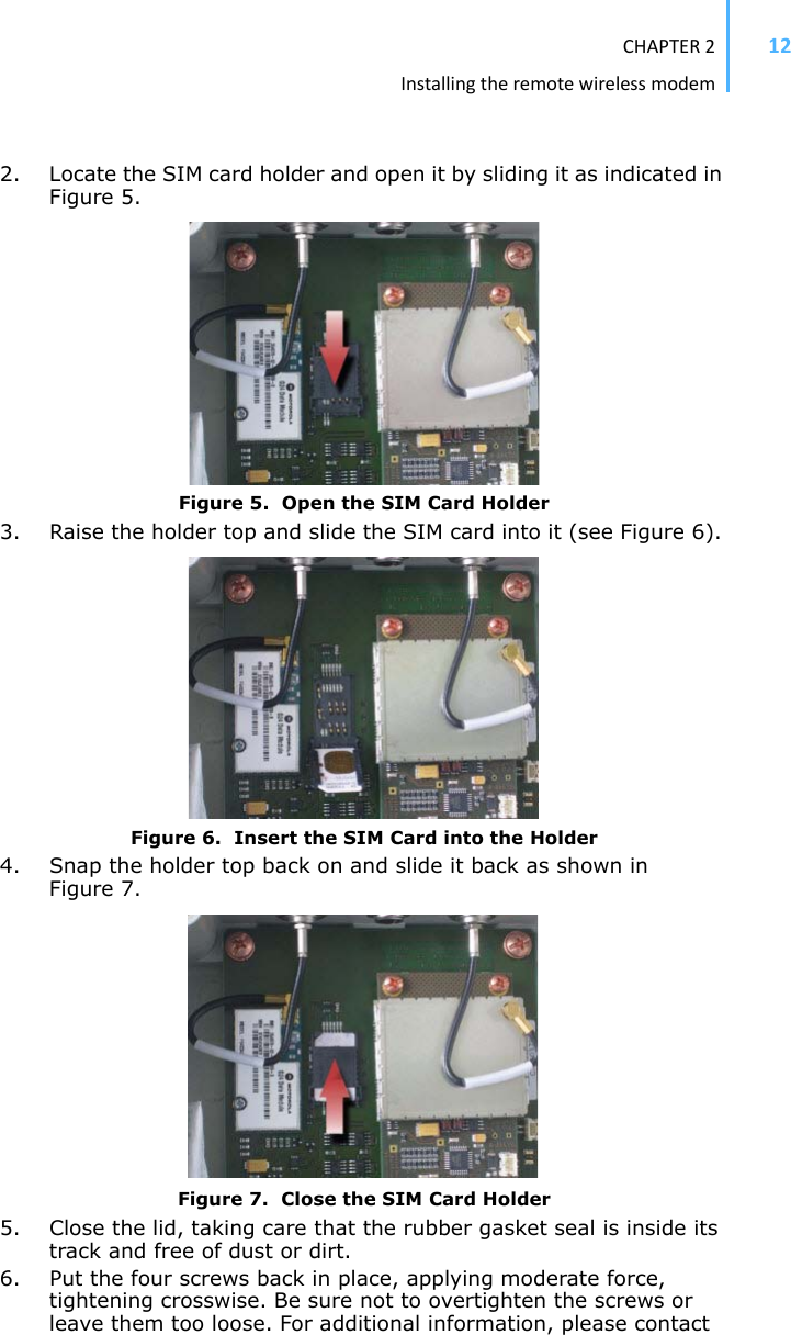
UserManual.wiki
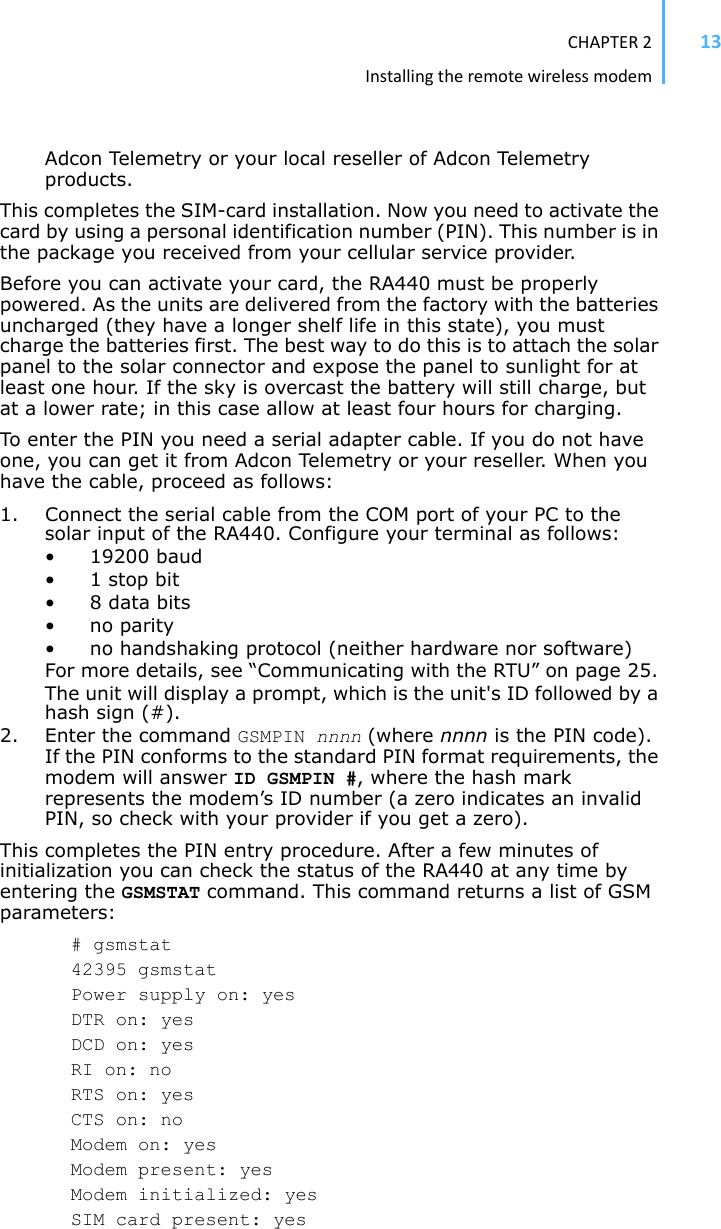
>
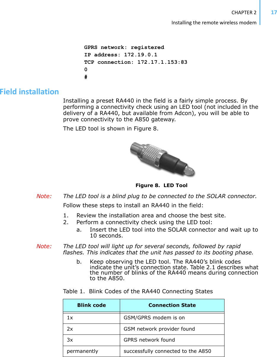
Ott Hydromet Business Unit Adcon Telemetry
>
RA440 46 User Manual
User Manual
Navigation menu
Upload a User Manual
Namespaces
Wiki Guide
HTML
PDF
Info
Views
User Manual
Discussion / Help
Navigation

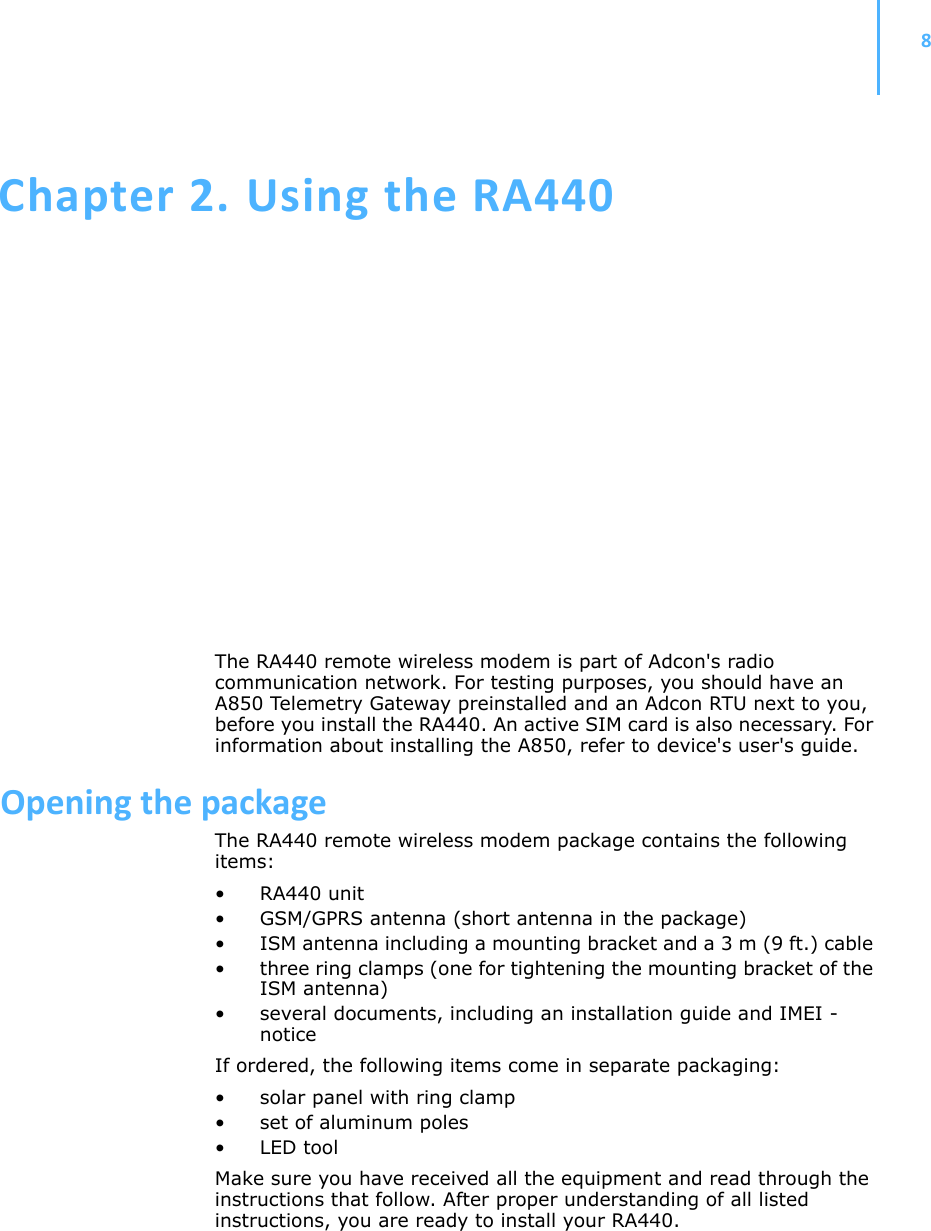
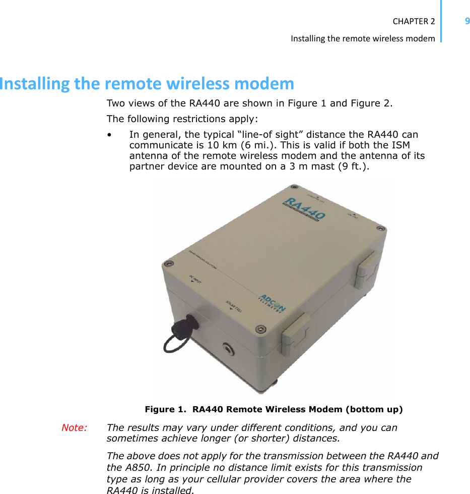
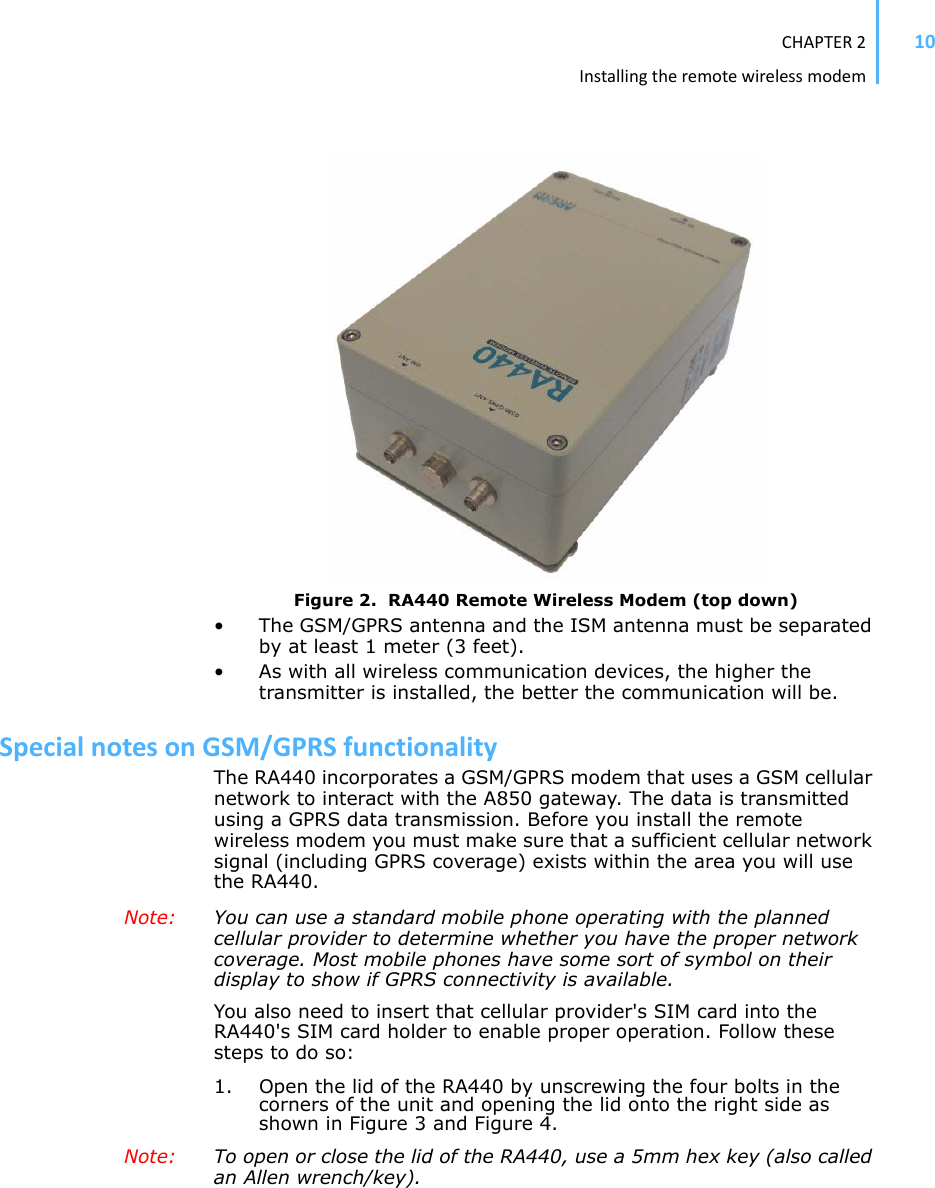
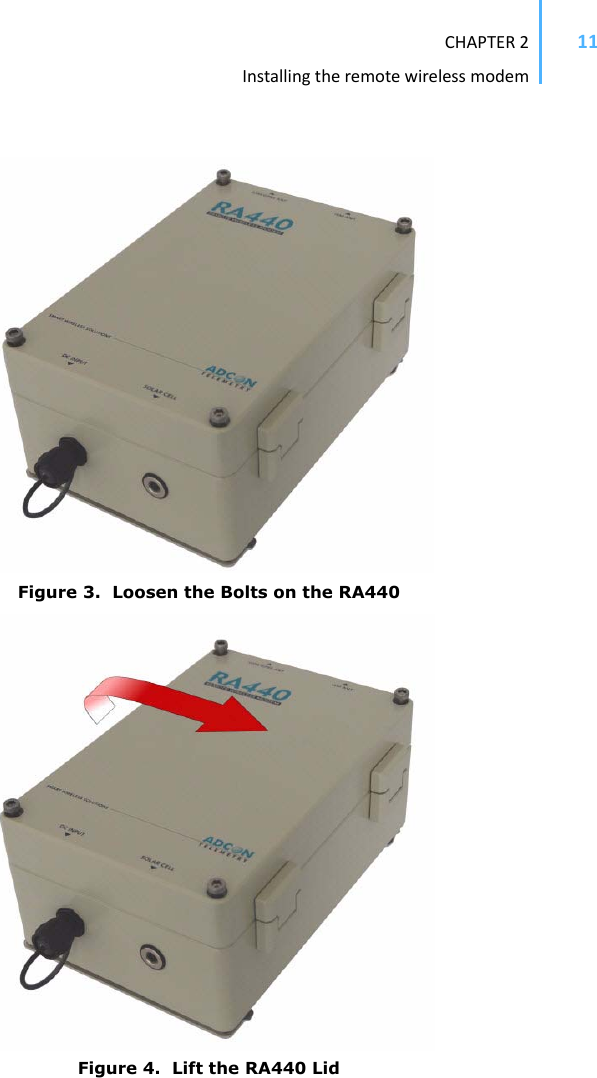
![CHAPTER2Installingtheremotewirelessmodem14PIN required: yes PIN accepted: yes PIN count: 3 PUK required: no GSM network: registered Operator: T-Mobile Austria Signal quality: 31 99 Phone call: no GPRS network: registered IP address: no TCP connection: no 0#The above system output shows that: • The GSM/GPRS modem is present and activated. • A valid SIM card is inserted. • The SIM card was activated with the valid PIN code. Note: The user can enter the PIN code a maximum of three times. Because the PIN count in the example shows three entries left, the PIN code was correctly entered on the first try. • A GSM network was detected with the operator name T-MobileAustria.• The signal quality range is between 1 and 31, where 31 is the best possible cellular coverage. Note: The parameters GPRS network,IP address, and TCP connectionchange after the GPRS settings are entered. To enable the data connection between the A850 and the RA440, certain steps must be executed. These steps are split into three sections: 1. Configuring the GPRS parameters 2. Configuring the TCP parameters 3. Configuring the A850-RA440 Connection settings ConfiguringtheGPRSparametersPrepare the GPRS parameters provided by your cellular network provider to enable proper GPRS operation of the RA440. Following are the GPRS configuration settings: GPRSAPNSERV "[servername]"where [servername] is the name of the network provider's GPRS access server (required)](https://usermanual.wiki/Ott-Hydromet-Business-Unit-Adcon-Telemetry/RA440-46/User-Guide-1160757-Page-14.png)
![CHAPTER2Installingtheremotewirelessmodem15GPRSAPNUN "[username]"where [username] is the name of the GPRS user's name for the network provider (might be optional)GPRSAPNPW "[password]"where [password] is the password for the GPRS user (might be optional)The following examples show the GRPS parameters for an Austrian mobile phone services provider: GPRSAPNSERV "A1.net"GPRSAPNUN "ppp@A1plus.at"GPRSAPNPW "ppp"0 CAUTION Parameter values are case sensitive. Be sure to correctly spell the values of the GPRS parameters and use the appropriate case. Misspelled names/entries could cause the RTU not to connect to the GPRS network or A850.ConfiguringtheTCPParametersThe RA440 will connect to the A850 only if the following TCP connection parameters are set properly: GPRSCONNADDR "[a850-ipaddress]" "[portnumber]"where [a850-ipaddress] is the IP address of the A850 the RA440 has to connect to and [portnumber] is the port number where the communication with the gateway will occur; the IP address parameter must be in decimal dotted notation, e.g. 198.182.196.56 (required) GPRSDNS "[ipaddress]"where [ipaddress] is the DNS server address of your GPRS network operator (optional)Note: When using an Internet firewall in front of the LAN where the A850 Telemetry Gateway resides, be careful to properly configure the firewall and the GPRSCONNADDR parameters [a850-ipaddress] and [portnumber]. This is particularly important if you use NAT (network address translation) on your firewall. 0 CAUTION If you are using an Internet firewall in front of your A850 Telemetry Gateway, allow connection to devices only with IP addresses from your GPRS network operator's IP networks to your A850 Telemetry Gateway. When your GPRS network operator’s IP network addresses changes, you must adjust your firewall's filters appropriately.ConfiguringtheRA440GPRSconnectionsettingsUse the following commands to define the intervals the RA440 will wake up and connect to the A850 Telemetry Gateway:](https://usermanual.wiki/Ott-Hydromet-Business-Unit-Adcon-Telemetry/RA440-46/User-Guide-1160757-Page-15.png)
![CHAPTER2Installingtheremotewirelessmodem16GPRSCONNALIGN [align]alignment of calls in seconds (default: 0, i.e. 00:00 = midnight)GPRSCONNINT [interval]interval in seconds between two connection attempts (default: 3600)GPRSSECRET [secret]this 32-bit integer (0 -4294967295) has to be set for the RA440 and the gateway; this is a shared "secret" or passwordGPRSTMOUT [interval]idle timeout in seconds (default: 3600); connections that are idle this long will be terminated by the RA440Set these parameters according to the needs of your application. Make sure you choose the proper parameters for GPRSTMOUT (to allow for appropriate idle times, but not ones that are too long), GPRSCONNALIGN, and GPRSCONNINT (for specifying the proper connect times of the RTU). Also take into account that the RA440 will be polled for data requests by the Adcon Telemetry Gateway within the GPRSTMOUT time. After entering all parameters correctly, you can check your settings at any time by entering the GSMSTAT command again. With the GPRS parameters set, the response will be similar to the following: # gsmstat 42395 gsmstat Power supply on: yes DTR on: yes DCD on: yes RI on: no RTS on: yes CTS on: no Modem on: yes Modem present: yes Modem initialized: yes SIM card present: yes PIN required: yes PIN accepted: yes PIN count: 3 PUK required: no GSM network: registered Operator: T-Mobile Austria Signal quality: 31 99 Phone call: no](https://usermanual.wiki/Ott-Hydromet-Business-Unit-Adcon-Telemetry/RA440-46/User-Guide-1160757-Page-16.png)
![CHAPTER3Upgradingthefirmware26In bootloader mode, the command line interface’s prompt is the character >. Therefore, to reboot the RA440 type the following after you see the > prompt: rebootAn alternative way to boot the unit is to disconnect the battery and after a few seconds reconnect it.For a list of the available commands, type Help at the > prompt.Available commands:upgrade [baudrate] ... upgrade from Y-modem downloadversion ... show the version of the bootloaderstate ... show the board statereboot [id] ... reboot the RA440firmware ... start the firmwarehelp ... display this help textNote: For some commands, such as the reboot command, you can supply the ID of the device. FirmwaremodeWhen you enter firmware mode, the following message is displayed in the Hyperterminal window:Checking firmware ... firmware found!41239 0#The bootloader scans the program memory for a valid firmware by testing the checksum, which takes a moment. If everything is correct, the "firmware found!" message appears.After the initialization process is done, which may take a moment, the device's identification number (for example, 41239) and error code (in this example, 0) are displayed. After another moment, the firmware mode’s command line interface prompt is displayed (#). If you need to return to bootloader mode when you’re in firmware mode, enter the Reboot command at the prompt.See “Using terminal commands” on page 30 for commands available in firmware mode.UpgradingthefirmwareNote: This section is included for informational purposes. You will rarely need to upgrade the firmware. However, when you do need to do so,](https://usermanual.wiki/Ott-Hydromet-Business-Unit-Adcon-Telemetry/RA440-46/User-Guide-1160757-Page-26.png)
![CHAPTER3Upgradingthefirmware28Figure 13. Hyperterminal and Com Port Properties Dialogs5. In the Bitspersecond field, select 115200.6. Select OK in the com port’s Properties dialog to close it.7. Select OK in the hyperterminal’s Properties dialog to close it.8. Back in the hyperterminal window, press Enter to continue the upgrade.---------------------------------------------------The current firmware image must be erased for the upload.If you continue now, you *MUST* upload a valid firmware image for an RA440!Continue? [y/n]:0 WARNING When you continue with the upgrade process, any existing firmware image in the RA440’s flash memory will be erased! You must supply a valid image for upload or the RA440 will have only bootloader capabilities (that is, it will have no radio capabilities).9. Enter Y to continue the upgrade.The bootloader starts sending the letter C (for connect)](https://usermanual.wiki/Ott-Hydromet-Business-Unit-Adcon-Telemetry/RA440-46/User-Guide-1160757-Page-28.png)