Ott Hydromet Business Unit Adcon Telemetry RA440-46 Telemetry Gateway transmitter User Manual RA440 Users Guide final1
Adcon Telemetry GmbH Telemetry Gateway transmitter RA440 Users Guide final1
User Manual

RA440RemoteWireless
Modem
UserGuide
SMARTWIRELESSSOLUTIONS

Proprietary Notice
The Adcon logo, Adcon Telemetry, Smart Wireless Solutions, the A720, A723 and A730 series,
RA440, addIT, addWAVE, the A840 and A850 series and Telemetry Gateway, AgroExpert,
addVANTAGE®, addVANTAGE Lite and addVANTAGE Pro are trademarks or registered
trademarks of Adcon Telemetry GmbH.
Neither the whole nor any part of the information contained in this publication may be
reproduced in any material form except with the prior written permission of Adcon
Telemetr y Gm b H .
This publication is intended only to assist the reader in the use of the product. Adcon
Telemetry GmbH shall not be liable for any loss or damage arising from the use of any
information in this publication, or any error or omission in such information, or any incorrect
use of the product.
Document Release 1.0, July 2009
Copyright ©2009 by Adcon Telemetry GmbH.
All rights reserved.

3
Contents
Chapter 1.Introduction____________________________________ 5
AbouttheRA440remotewirelessmodem _____________________ 5
Compliancestatementandwarnings _________________________ 6
Conventions _____________________________________________ 6
Chapter 2.UsingtheRA440 ________________________________ 8
Openingthepackage ______________________________________ 8
Installingtheremotewirelessmodem ________________________ 9
SpecialnotesonGSM/GPRSfunctionality __________________ 10
ConfiguringtheGPRSparameters _____________________ 14
ConfiguringtheTCPParameters_______________________ 15
ConfiguringtheRA440GPRSconnectionsettings _________ 15
Fieldinstallation ______________________________________ 17
MoreabouttheLEDtool _______________________________ 19
ConfiguringanRA440inthetelemetrygateway________________ 19
Maintainingandservicingtheremotewirelessmodem__________ 19
TheRA440internalbatteries ____________________________ 19
Replacingtheinternalbattery ___________________________ 21

Contents 4
Chapter 3.PerformingAdvancedFunctions __________________ 22
Understandingconnectors_________________________________ 22
TheSOLARCELLconnector _____________________________ 23
TheDCINPUTconnector _______________________________ 24
CommunicatingwiththeRTU ______________________________ 25
BootingtheRA440 _______________________________________ 25
Bootloadermode _____________________________________ 25
Firmwaremode ______________________________________ 26
Upgradingthefirmware___________________________________ 26
Serialcommunicationprotocol _____________________________ 29
Generalformatofacommand___________________________ 29
Generalformatofananswer ____________________________ 30
Usingterminalcommands _________________________________ 30
Returnederrorslist ______________________________________ 50
Commandlineinterpreter ______________________________ 50
Devicedescriptorandstoragehandler ____________________ 50
Realtimeclock _______________________________________ 51
Radiointerface(includingGSM/GPRSModem)______________ 51
Notifications _________________________________________ 51
Performingconnectivitychecks_____________________________ 51
Specifications___________________________________________ 53
Index ________________________________________________ 56

5
Chapter 1.Introduction
This manual explains the hardware aspects of Adcon’s RA440 remote
wireless modems, including installation issues and certain parameter
configurations. The manual is divided as follows:
•Introduction, which gives some general information and
document conventions.
•Using the RA440, which details the installation and use of the
remote wireless modem.
•Performing Advanced Functions, which discusses connectors and
controllers and provides other information for advanced users.
•Specifications, which describes operating parameters for the
devices.
AbouttheRA440remotewirelessmodem
The RA440 remote wireless modem is a low-power, medium-range
modem device that is capable of communicating with an A733 by
using Adcon's radio protocol and an A850 Gateway over a GPRS
connection to respond to data polling requests.
The unit incorporates an A431 radio module operating in the 432 to
470 MHz frequency range, making it adaptable to most radio
communication regulations in the world. The output power is 500 mW,
while the modulation is narrow-band FM (20 or 25 kHz channel
spacing). Additionally the RA440 incorporates a GSM/GPRS module
and uses the standard GSM network for retrieving commands (900/
1800 MHz in Europe, 850/1900 MHz in the US).

CHAPTER1
Compliancestatementandwarnings
6
Due to its construction as well as to the software controlling it, the
power consumption is extremely low. The unit operates off an internal
6.2 volt rechargeable battery, which is charged either by a solar panel
or an external power adapter. A special configuration can be
implemented where an external 12 volt (rechargeable) battery can be
used in addition to or instead of the internal rechargeable batteries.
The external rechargeable battery will not be recharged by the RA440.
The RA440 is a ruggedized unit, complying with the IP65
environmental protection class (NEMA 4). You can easily install and
integrate the unit into an Adcon A733 network. Depending on the
topography, you can get a reliable wireless connection to an A733
series device up to 20 km (12 mi.) away. Under favorable conditions,
the distance can be even farther. You should be aware that the RA440
operates within the GSM/GPRS network coverage provided by your
local cellular provider.
Compliancestatementandwarnings
The RA440 remote wireless modem must not be used with any
antenna other than the one supplied by Adcon (or an antenna with
identical technical specifications). A minimum distance of 20cm
(7.9 in.) to the antenna is required to guarantee compliance with
basic safety restrictions.
In conformity with EC Parliament recommendation 1999/519/EG,
28V/m is the reference value for the frequency range used. By
adhering to any and all recommended reference levels, you can
ensure compliance to basic restrictions that protect the general public
against electromagnetic fields.
This device complies with part 15 of the FCC Rules. Operation is
subject to the following two conditions:
1. This device must not cause harmful interference.
2. This device must accept any interference received, including
interference that might cause undesired operation.
Changes or modifications not expressly approved by Adcon Telemetry
for compliance could void your authority to operate the equipment.
Conventions
Certain conventions apply in this document.
Italics Indicate that the text is variable and must be
substituted for something specific, as indicated in
the explanation. Italics can also be used to
emphasize words as words or letters as letters.
Bold Indicates special emphasis of the text. Also
indicates menu names and items in a window.

CHAPTER1
Conventions
7
fixed font Indicates characters you must type or system
messages.
FileSave Indicates menu selection. For example, select the
File menu, then the Save option.
Note Indicates information of interest. Notes appear
after the information they apply to.
0CAUTION Indicates that you may get unexpected results if
you don’t follow the instructions. Cautions appear
before the information they apply to.
0WARNING Indicates danger to yourself or damage to the
device if you don’t follow the instructions.
Warnings appear before the information they
apply to.

8
Chapter 2.UsingtheRA440
The RA440 remote wireless modem is part of Adcon's radio
communication network. For testing purposes, you should have an
A850 Telemetry Gateway preinstalled and an Adcon RTU next to you,
before you install the RA440. An active SIM card is also necessary. For
information about installing the A850, refer to device's user's guide.
Openingthepackage
The RA440 remote wireless modem package contains the following
items:
• RA440 unit
• GSM/GPRS antenna (short antenna in the package)
• ISM antenna including a mounting bracket and a 3 m (9 ft.) cable
• three ring clamps (one for tightening the mounting bracket of the
ISM antenna)
• several documents, including an installation guide and IMEI -
notice
If ordered, the following items come in separate packaging:
• solar panel with ring clamp
• set of aluminum poles
•LED tool
Make sure you have received all the equipment and read through the
instructions that follow. After proper understanding of all listed
instructions, you are ready to install your RA440.
CHAPTER2
Installingtheremotewirelessmodem
9
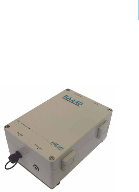
Installingtheremotewirelessmodem
Two views of the RA440 are shown in Figure 1 and Figure 2.
The following restrictions apply:
• In general, the typical “line-of sight” distance the RA440 can
communicate is 10 km (6 mi.). This is valid if both the ISM
antenna of the remote wireless modem and the antenna of its
partner device are mounted on a 3 m mast (9 ft.).
Figure 1. RA440 Remote Wireless Modem (bottom up)
Note: The results may vary under different conditions, and you can
sometimes achieve longer (or shorter) distances.
The above does not apply for the transmission between the RA440 and
the A850. In principle no distance limit exists for this transmission
type as long as your cellular provider covers the area where the
RA440 is installed.
CHAPTER2
Installingtheremotewirelessmodem
10
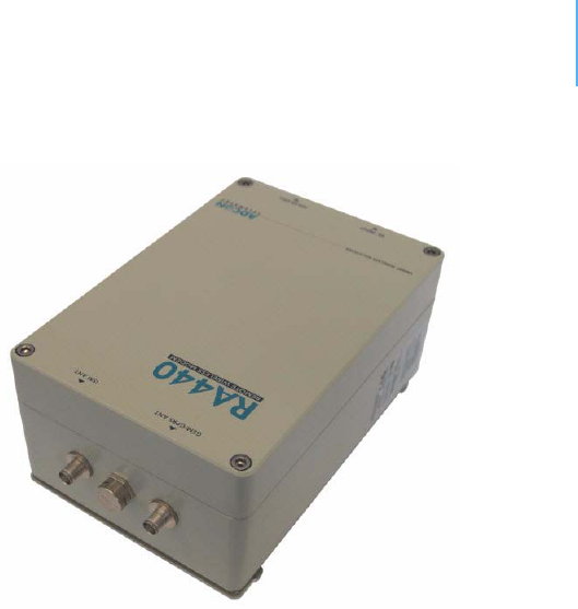
Figure 2. RA440 Remote Wireless Modem (top down)
• The GSM/GPRS antenna and the ISM antenna must be separated
by at least 1 meter (3 feet).
• As with all wireless communication devices, the higher the
transmitter is installed, the better the communication will be.
SpecialnotesonGSM/GPRSfunctionality
The RA440 incorporates a GSM/GPRS modem that uses a GSM cellular
network to interact with the A850 gateway. The data is transmitted
using a GPRS data transmission. Before you install the remote
wireless modem you must make sure that a sufficient cellular network
signal (including GPRS coverage) exists within the area you will use
the RA440.
Note: You can use a standard mobile phone operating with the planned
cellular provider to determine whether you have the proper network
coverage. Most mobile phones have some sort of symbol on their
display to show if GPRS connectivity is available.
You also need to insert that cellular provider's SIM card into the
RA440's SIM card holder to enable proper operation. Follow these
steps to do so:
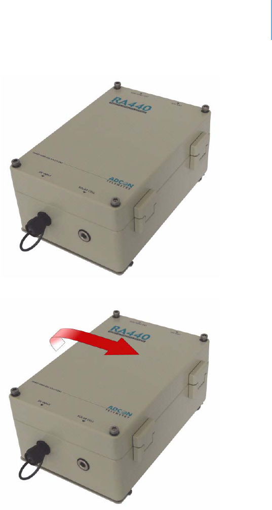
1. Open the lid of the RA440 by unscrewing the four bolts in the
corners of the unit and opening the lid onto the right side as
shown in Figure 3 and Figure 4.
Note: To open or close the lid of the RA440, use a 5mm hex key (also called
an Allen wrench/key).
CHAPTER2
Installingtheremotewirelessmodem
11
Figure 3. Loosen the Bolts on the RA440
Figure 4. Lift the RA440 Lid
CHAPTER2
Installingtheremotewirelessmodem
12
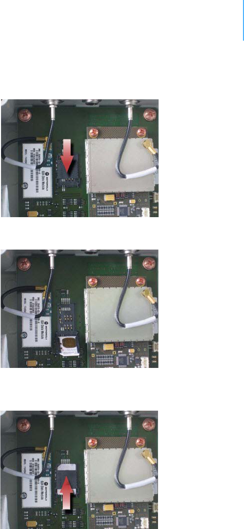
2. Locate the SIM card holder and open it by sliding it as indicated in
Figure 5.
Figure 5. Open the SIM Card Holder
3. Raise the holder top and slide the SIM card into it (see Figure 6).
Figure 6. Insert the SIM Card into the Holder
4. Snap the holder top back on and slide it back as shown in
Figure 7.
Figure 7. Close the SIM Card Holder
5. Close the lid, taking care that the rubber gasket seal is inside its
track and free of dust or dirt.
6. Put the four screws back in place, applying moderate force,
tightening crosswise. Be sure not to overtighten the screws or
leave them too loose. For additional information, please contact

CHAPTER2
Installingtheremotewirelessmodem
13
Adcon Telemetry or your local reseller of Adcon Telemetry
products.
This completes the SIM-card installation. Now you need to activate the
card by using a personal identification number (PIN). This number is in
the package you received from your cellular service provider.
Before you can activate your card, the RA440 must be properly
powered. As the units are delivered from the factory with the batteries
uncharged (they have a longer shelf life in this state), you must
charge the batteries first. The best way to do this is to attach the solar
panel to the solar connector and expose the panel to sunlight for at
least one hour. If the sky is overcast the battery will still charge, but
at a lower rate; in this case allow at least four hours for charging.
To enter the PIN you need a serial adapter cable. If you do not have
one, you can get it from Adcon Telemetry or your reseller. When you
have the cable, proceed as follows:
1. Connect the serial cable from the COM port of your PC to the
solar input of the RA440. Configure your terminal as follows:
• 19200 baud
•1 stop bit
• 8 data bits
• no parity
• no handshaking protocol (neither hardware nor software)
For more details, see “Communicating with the RTU” on page 25.
The unit will display a prompt, which is the unit's ID followed by a
hash sign (#).
2. Enter the command GSMPIN nnnn (where nnnn is the PIN code).
If the PIN conforms to the standard PIN format requirements, the
modem will answer ID GSMPIN #, where the hash mark
represents the modem’s ID number (a zero indicates an invalid
PIN, so check with your provider if you get a zero).
This completes the PIN entry procedure. After a few minutes of
initialization you can check the status of the RA440 at any time by
entering the GSMSTAT command. This command returns a list of GSM
parameters:
# gsmstat
42395 gsmstat
Power supply on: yes
DTR on: yes
DCD on: yes
RI on: no
RTS on: yes
CTS on: no
Modem on: yes
Modem present: yes
Modem initialized: yes
SIM card present: yes

CHAPTER2
Installingtheremotewirelessmodem
14
PIN required: yes
PIN accepted: yes
PIN count: 3
PUK required: no
GSM network: registered
Operator: T-Mobile Austria
Signal quality: 31 99
Phone call: no
GPRS network: registered
IP address: no
TCP connection: no
0
#
The above system output shows that:
• The GSM/GPRS modem is present and activated.
• A valid SIM card is inserted.
• The SIM card was activated with the valid PIN code.
Note: The user can enter the PIN code a maximum of three times. Because
the PIN count in the example shows three entries left, the PIN code
was correctly entered on the first try.
• A GSM network was detected with the operator name T-Mobile
Austria.
• The signal quality range is between 1 and 31, where 31 is the
best possible cellular coverage.
Note: The parameters GPRS network,IP address, and TCP connection
change after the GPRS settings are entered.
To enable the data connection between the A850 and the RA440,
certain steps must be executed. These steps are split into three
sections:
1. Configuring the GPRS parameters
2. Configuring the TCP parameters
3. Configuring the A850-RA440 Connection settings
ConfiguringtheGPRSparameters
Prepare the GPRS parameters provided by your cellular network
provider to enable proper GPRS operation of the RA440. Following are
the GPRS configuration settings:
GPRSAPNSERV "[servername]"
where [servername] is the name of the network
provider's GPRS access server (required)

CHAPTER2
Installingtheremotewirelessmodem
15
GPRSAPNUN "[username]"
where [username] is the name of the GPRS user's name
for the network provider (might be optional)
GPRSAPNPW "[password]"
where [password] is the password for the GPRS user
(might be optional)
The following examples show the GRPS parameters for an Austrian
mobile phone services provider:
GPRSAPNSERV "A1.net"
GPRSAPNUN "ppp@A1plus.at"
GPRSAPNPW "ppp"
0 CAUTION Parameter values are case sensitive. Be sure to correctly spell the
values of the GPRS parameters and use the appropriate case.
Misspelled names/entries could cause the RTU not to connect to the
GPRS network or A850.
ConfiguringtheTCPParameters
The RA440 will connect to the A850 only if the following TCP
connection parameters are set properly:
GPRSCONNADDR "[a850-ipaddress]" "[portnumber]"
where [a850-ipaddress] is the IP address of the A850
the RA440 has to connect to and
[portnumber] is the port number where the
communication with the gateway will occur; the IP
address parameter must be in decimal dotted notation,
e.g. 198.182.196.56 (required)
GPRSDNS "[ipaddress]"
where [ipaddress] is the DNS server address of your
GPRS network operator (optional)
Note: When using an Internet firewall in front of the LAN where the A850
Telemetry Gateway resides, be careful to properly configure the
firewall and the GPRSCONNADDR parameters [a850-ipaddress] and
[portnumber]. This is particularly important if you use NAT (network
address translation) on your firewall.
0 CAUTION If you are using an Internet firewall in front of your A850 Telemetry
Gateway, allow connection to devices only with IP addresses from
your GPRS network operator's IP networks to your A850 Telemetry
Gateway. When your GPRS network operator’s IP network addresses
changes, you must adjust your firewall's filters appropriately.
ConfiguringtheRA440GPRSconnectionsettings
Use the following commands to define the intervals the RA440 will
wake up and connect to the A850 Telemetry Gateway:

CHAPTER2
Installingtheremotewirelessmodem
16
GPRSCONNALIGN [align]
alignment of calls in seconds (default: 0, i.e. 00:00 =
midnight)
GPRSCONNINT [interval]
interval in seconds between two connection attempts
(default: 3600)
GPRSSECRET [secret]
this 32-bit integer (0 -4294967295) has to be set for
the RA440 and the gateway; this is a shared "secret" or
password
GPRSTMOUT [interval]
idle timeout in seconds (default: 3600); connections
that are idle this long will be terminated by the RA440
Set these parameters according to the needs of your application. Make
sure you choose the proper parameters for GPRSTMOUT (to allow for
appropriate idle times, but not ones that are too long),
GPRSCONNALIGN, and GPRSCONNINT (for specifying the proper
connect times of the RTU). Also take into account that the RA440 will
be polled for data requests by the Adcon Telemetry Gateway within
the GPRSTMOUT time.
After entering all parameters correctly, you can check your settings at
any time by entering the GSMSTAT command again. With the GPRS
parameters set, the response will be similar to the following:
# gsmstat
42395 gsmstat
Power supply on: yes
DTR on: yes
DCD on: yes
RI on: no
RTS on: yes
CTS on: no
Modem on: yes
Modem present: yes
Modem initialized: yes
SIM card present: yes
PIN required: yes
PIN accepted: yes
PIN count: 3
PUK required: no
GSM network: registered
Operator: T-Mobile Austria
Signal quality: 31 99
Phone call: no

CHAPTER2
Installingtheremotewirelessmodem
17
GPRS network: registered
IP address: 172.19.0.1
TCP connection: 172.17.1.153:83
0
#
Fieldinstallation
Installing a preset RA440 in the field is a fairly simple process. By
performing a connectivity check using an LED tool (not included in the
delivery of a RA440, but available from Adcon), you will be able to
prove connectivity to the A850 gateway.
The LED tool is shown in Figure 8.
Figure 8. LED Tool
Note: The LED tool is a blind plug to be connected to the SOLAR connector.
Follow these steps to install an RA440 in the field:
1. Review the installation area and choose the best site.
2. Perform a connectivity check using the LED tool:
a. Insert the LED tool into the SOLAR connector and wait up to
10 seconds.
Note: The LED tool will light up for several seconds, followed by rapid
flashes. This indicates that the unit has passed to its booting phase.
b. Keep observing the LED tool. The RA440’s blink codes
indicate the unit’s connection state. Table 2.1 describes what
the number of blinks of the RA440 means during connection
to the A850.
Table 1. Blink Codes of the RA440 Connecting States
Blink code Connection State
1x GSM/GPRS modem is on
2x GSM network provider found
3x GPRS network found
permanently successfully connected to the A850

CHAPTER2
Installingtheremotewirelessmodem
18
3. Unpack the pole set.
4. Using a sledge hammer, drive the base pole (pointed tip) into the
ground until it is securely and tightly seated. To prevent damage
to the top of this pole, be sure to put a protective cap on top of it
prior to pounding it in. Such a pole pounder can be ordered from
your Adcon distributor (item number 900.000.014).
5. Using a ring clamp, fasten the solar panel onto the aluminum
pole. Make sure that the panel is facing south (north if you are
located in the southern hemisphere) and out of the way of the
RA440 or its antennas.
Note: The solar panel can be mounted under or behind the RA440, but be
sure that the unit does not shadow the panel. You can avoid certain
communication problems by not settling the panel directly behind one
of the antennas.
6. Fasten the external ISM antenna’s mounting bracket to the top of
the pole using another ring clamp and place the RA440 at least 1
meter (3 feet) under the ISM antenna. Adcon recommends that
you perform another connectivity test, if you can, to check the
positioning of the device.
Note: If you incorporate the RA440 into an existing Adcon network, Adcon
strongly recommends that you perform connection checks to nearby
RTUs (see “Performing connectivity checks” on page 51 for details).
7. Attach the solar panel to the SOLAR CELL connector by turning
the plugs’ fastening screws clockwise until secure.
8. Secure the extra length of the cable to the pole with UV-resistant
cable ties.
Note: Regardless of how you will power your RA440, you should connect the
LED tool first. Using the internal batteries to power the unit enables
you to see the full startup phase that is initiated by the LED tool.
When you use the RA440 with an external 12 volt rechargeable
battery, the unit starts to operate at the same time you connect your
battery to the DC INPUT and you might miss the beginning of the
startup phase.
This completes the installation of your RA440. If the SOLAR CELL
connector or the DC INPUT connector is left unused, use the cap
provided to protect it against moisture and dust. Be sure to keep the
following information in a place you can remember:
• Serial number of the RA440 and the A440 (both are printed on
the type plate)
• Location of the RA440
Note: This information will be necessary during the configuration of the
device at the A850 Gateway.

CHAPTER2
ConfiguringanRA440inthetelemetrygateway
19
MoreabouttheLEDtool
The LED tool allows you to rapidly check the status of an RA440. After
you insert the LED tool into the SOLAR CELL connector, the unit tries
to reconnect to the A850 gateway configured previously on the
RA440. Table 1 on page 17 describes the LED blinking codes for the
RA440.
If the RA440 is not connected to the A850, the unit flashes rapidly to
let you know the unit is alive. These flashes occur every half second.
If the internal battery levels drop below 5.6 volts and the external
battery drops below 11 volts, the unit will enter the misery state. In
this state the unit reduces its activities to a minimum. The radio unit is
turned off, the GPRS connection to the A850 gateway is terminated,
and communication over the serial communication cable is impossible.
Only the internal real-time clock is maintained and the power
management functions are performed.
If the internal battery levels drop below 5.2 volts and the external
battery drops below approximately 10 volts, the system switches
completely off, effectively decoupling itself from the battery in order to
protect it.
Note: If the LED tool was connected to the RA440 when the unit shut down,
the LED tool will restart the RA440, which will initiate a shutdown
again. If this happens to you, disconnect the LED tool and replace/
recharge the batteries. (This does not apply if a solar panel is
connected to the SOLAR connector.)
ConfiguringanRA440inthetelemetrygateway
To configure the RA440 with an A850 Telemetry Gateway, refer to the
A850 Telemetry Gateway User's Guide.
Maintainingandservicingtheremotewirelessmodem
An RA440 needs virtually no maintenance. It is waterproof and
designed to withstand harsh environmental conditions (-30 to +70 °C,
or -22 to 158 °F), high RH values, water, and other non-corrosive
liquids. It conforms to the European protection class IP65. This applies
also to the connectors, as long as they are mated. Don’t let unmated
connectors on the RA440 be exposed to the environment for extended
periods of time as this might seriously affect their functionality.
TheRA440internalbatteries
The internal batteries supply 6.2 volts and consist of one or two NiMH
packs.
Note: The RA440 is shipped with one battery pack, but will hold two packs.
The book documents the use of the RA440 with two NiMH battery
packs.

CHAPTER2
Maintainingandservicingtheremotewirelessmodem
20
The internal electronics manage the batteries’ charging/discharging
process, ensuring a long lifetime. This approach, coupled with a
remarkably low average power consumption, allows an RA440 to
operate approximately one week on two fully charged battery packs,
under the following conditions:
• The radio quality of the GPRS cellular network and the Adcon
proprietary network is classified as good. Following conditions
classify the radio quality as good:
• GPRS cellular network quality is greater than 29.
• The network quality is readable at the response of the GSMSQ
command at signal quality (1st parameter).
Adcon’s proprietary network signal quality might get by using the
INFO command (see page 43).
• The channel used for your Adcon proprietary network has
moderate radio activity, with requests every 15 minutes.
Table 2 shows the device’s expected operation time on a fully charged
battery under various conditions.
Note: “Radio activity” means that one base station and one to five RTUs are
active on the same operating frequency and within the transmission
distance of the RA440.
The operation time might differ due to the individual setting of
A440TMOUT and the polling cycle of the connected RTUs.
However, if for some reason (wear-out or accident) the batteries lose
their capacity (noted in the software with repeated “Battery low”
messages), they must be replaced. Make sure, though, that the
problem is really due to the batteries and not to a defective or dirty
solar panel.
Adcon highly recommends that you frequently check and clean your
solar panels. Rain and dust can cover the solar panel’s surface with a
thin layer of dirt, effectively reducing its power output. Surrounding
vegetation can also lower panel efficiency.
Table 2. Device Operation Time
Radio
Activity
Connected
Batteries (Internal)
Average
Consumption
(mA)
Estimated
Operation (days)
No 1 15.625 8
Yes 1 35.715 3.5
No 2 15.625 16
Yes 2 35.715 7
CHAPTER2
Maintainingandservicingtheremotewirelessmodem
21
Replacingtheinternalbattery
If you have verified that the batteries need to be replaced, follow
these steps to do so:
1. Open the lid of the RA440 by unscrewing the four bolts in the
corners of the unit and opening the lid onto the right side, as
shown in Figure 3 on page 11 and Figure 4 on page 11.
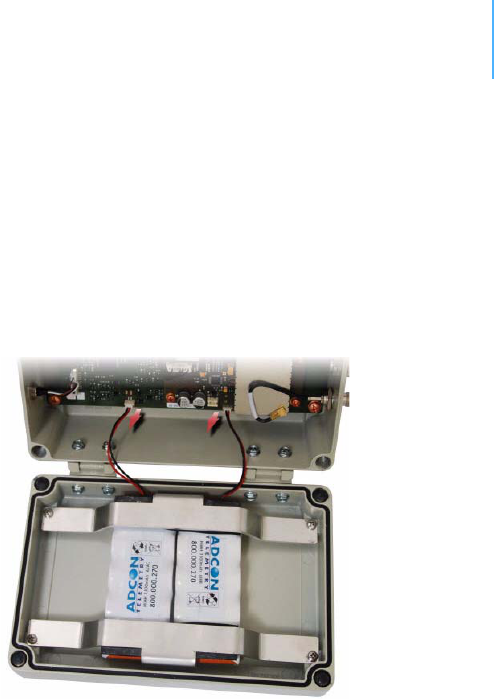
2. The battery packs are connected to the electronics board by
means of a PCB connector. Remove the plug of each pack from
the PCB connector, as shown in Figure 9.
Figure 9. Unplugging the PCB Connectors
3. Loosen all four screws of the battery holder that keeps the
batteries in place, then remove the cover and the batteries.
4. Remove the expired battery packs and replace them with new
ones (obtainable from Adcon).
5. Replace the battery packs and the battery holder and fasten the
four screws.
6. Insert the battery plug of both PCBs into the PCB connectors.
0 WARNING Be sure to mount the rubber gasket properly, so that the unit’s IP65
environmental protection is not affected. You must also be sure to not
squeeze the battery cable.
7. Close the lid, taking care that the rubber gasket sealing the box is
correctly in place and free of dirt and soil.
8. Put the four cover bolts back in place, applying a moderate force
and tightening crosswise.

22
Chapter 3.PerformingAdvanced
Functions
With the appropriate knowledge, you can configure RA440 remote
wireless modems in the field by using a hyperterminal window. To
configure the devices, you will need a special serial cable adapter (not
supplied, but available from your Adcon distributor).
0 CAUTION Do not try to configure your devices if you are not sure what to do—
the unit might not communicate with the remote measuring station or
function with the addVANTAGE software.
0 WARNING Tampering with parameters for the devices may void your warranty or
damage the device. In general, the commands described in this
chapter are intended for technical support staff and users with a great
deal of highly technical hardware and software experience.
In the system architecture, the base station and RA440 are both
considered to be nodes. The base station is called the master node, or
master, while the RA440 is called the slave node, or slave. The RA440
includes a base station and a virtual RTU (maintaining only, no sensor
data). Thus, to configure the RA440, you will need to insert two nodes
into your A850 Telemetry Gateway configuration.
Understandingconnectors
The devices have cable attachments called connectors. The connector
type determines how the device communicates with the sensors or the
computer.
CHAPTER3
Understandingconnectors
23
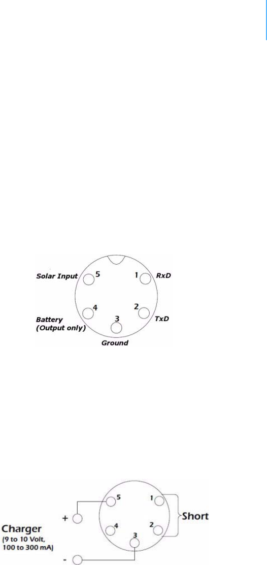
TheSOLARCELLconnector
The RA440 remote wireless modem has a SOLAR CELL connector used
to interact with the device. The connector features the following pins:
• Solar Input, which enables charging the internal batteries.
0 CAUTION To charge the unit without causing damage to the batteries or the
charging circuit, the following electrical characteristics must be
maintained:
• operating input voltage: 9 -10V
• maximum input current: 100 -300mA
• Battery, which enables powering external circuits. This pin is an
output-only pin. The maximum current drawn by the attached
circuit must not exceed 500 mA.
• RxD and TxD, which are used for serial communication (19200
baud) with the RA440. The pinout of the SOLAR CELL connector is
shown in Figure 10.
Figure 10. The Solar Cell Connector
Note: Unlike the usual power connectors, the RA440 SOLAR CELL connector
features no external battery power supply. Thus, the unit must be
used with an installed internal battery or an external battery
connected to the DC INPUT connector.
0 WARNING The serial communication line is 3V CMOS compatible. Therefore, a
special adapter cable must be used to reach the RS-232 levels.
You might want to charge the RA440 with something other than the
standard solar panel. In this case you must provide the electrical
characteristics and configuration shown in Figure 11.
Figure 11. Configuration for Charging the RA440

CHAPTER3
Understandingconnectors
24
TheDCINPUTconnector
The DC INPUT connector enables the RA440 devices to power the unit
by an external power supply or battery. This function mode is
restricted by the following statements:
• The external supply circuit in the RA440 is designed for a
standard 12 volt rechargeable battery. To ensure proper
functionality of the RA440, the following behavior was integrated
into the input circuit of the connector:
• To enable power supply from an external power source, the
input voltage must be greater than approximately 11.5 volts.
• After activation the power source may drop the voltage to
approximately 9.5 volts without deactivating the external
input.
• By running under the lower threshold, the input circuit
detaches the power source from the RA440 and uses the
internal batteries as the power supply.
0 CAUTION If the voltage of the external power source exceeds 18 volts, the
RA440 might be permanently damaged.
• The DC INPUT connector is an input only. It will not charge the
external battery.
• The external battery will not charge the internal batteries. Thus,
if you are using internal batteries in addition to an external one,
you must provide a separate charger, such as an Adcon solar
panel, to back up the internal batteries.
0 CAUTION To avoid damaging your RA440, be sure the charger you select does
not exceed the maximum output voltage.
Figure 12 displays the pinout of the DC INPUT connector.
Figure 12. DC INPUT Connector
Note: If you want to use an external power supply to power the RA440, you
need to have a special power cable equipped with the plug that
connects to the external DC INPUT. This cable is not included in the
standard delivery package and must be ordered separately from your
local Adcon distributor (order number: 800.440.001).

CHAPTER3
CommunicatingwiththeRTU
25
CommunicatingwiththeRTU
You can use a Windows Hyperterminal window to connect to the
RA440 remote wireless modem. After you have installed the system,
follow these steps to configure the device and set the default
parameters:
Note: To configure the RA440, you must have a special adapter cable (item
number 200.720.540 from your Adcon distributor) and plug it into the
SOLAR CELL connector.
1. Open a Hyperterminal window.
2. Select the appropriate serial port and click OK.
3. Configure your terminal as follows:
• 19200 baud
•1 stop bit
• 8 data bits
• No parity
• No protocol (neither hardware nor software)
4. Select OK to open the terminal window.
5. Press Enter to generate a response in the window.
Note: The RA440 has two command line modes, bootloader and firmware.
BootingtheRA440
Note: This section is included for informational purposes. You will rarely
need to boot the RA440. However, when you do need to do so, you
will work within a Windows Hyperterminal window on your computer.
Bootloadermode
When the RA440 starts from a power-up reset (such as when you
connect the battery to the unit), it enters the bootloader mode. If you
press no keys in the interim, the RA440 enters the firmware mode in
five seconds.
If you want to work with commands in the bootloader rather than
continuing to the firmware mode, press ESC within five seconds after
seeing the following sign-on message:
RA440 Bootloader V1.7
Copyright (C) Adcon Telemetry GmbH 2009
Press <ESC> within 5 seconds to start the commandline
interface...
You are in the command line interface of the bootloader. This interface
enables you to perform certain commands such as upgrading to a new
firmware or rebooting the device.
Note: If you press no keys within 60 seconds, the bootloader command line
interface will start firmware mode automatically.

CHAPTER3
Upgradingthefirmware
26
In bootloader mode, the command line interface’s prompt is the
character >. Therefore, to reboot the RA440 type the following after
you see the > prompt:
reboot
An alternative way to boot the unit is to disconnect the battery and
after a few seconds reconnect it.
For a list of the available commands, type Help at the > prompt.
Available commands:
upgrade [baudrate] ... upgrade from Y-modem download
version ... show the version of the bootloader
state ... show the board state
reboot [id] ... reboot the RA440
firmware ... start the firmware
help ... display this help text
Note: For some commands, such as the reboot command, you can supply
the ID of the device.
Firmwaremode
When you enter firmware mode, the following message is displayed in
the Hyperterminal window:
Checking firmware ... firmware found!
41239 0
#
The bootloader scans the program memory for a valid firmware by
testing the checksum, which takes a moment. If everything is correct,
the "firmware found!" message appears.
After the initialization process is done, which may take a moment, the
device's identification number (for example, 41239) and error code (in
this example, 0) are displayed. After another moment, the firmware
mode’s command line interface prompt is displayed (#).
If you need to return to bootloader mode when you’re in firmware
mode, enter the Reboot command at the prompt.
See “Using terminal commands” on page 30 for commands available
in firmware mode.
Upgradingthefirmware
Note: This section is included for informational purposes. You will rarely
need to upgrade the firmware. However, when you do need to do so,

CHAPTER3
Upgradingthefirmware
27
you will work within a Windows HyperTerminal window on your
computer.
Before upgrading the firmware, you must reboot the RA440 to access
the bootloader mode’s command line interface. Follow the procedure
described under Booting the RA440 to get into the bootloader.
Before you start the upgrade, it is very important that you copy the
firmware image to the hard drive of the computer you use in the field.
You also need to know which version of the bootloader you are
running. You can determine the version any of the following ways:
• Look at the bootloader’s sign-on message when you start it.
• At the bootloader mode’s > prompt, enter the Version
command.
• In firmware mode, enter the Reboot <ID> command and look at
the sign-on message.
• In firmware mode, enter ver at the # prompt.
Now you’re ready for the upgrade.
1. At the ’>’ prompt, enter the following command:
upgrade 115200
The upgrade process starts.
Note: For pre-1.7 versions of the bootloader, omit the speed parameter
(115200 used to be the default). For 1.7 and later versions, include
the 115200 baudrate parameter. If you do not specify a baudrate, the
upload runs at the default 19200 baudrate.
Change the baudrate of your terminal to '115200' and
hit <Return> to start flashing.
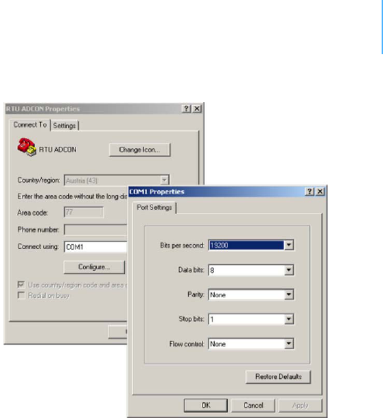
2. Select FileProperties to open the hyperterminal’s Properties
dialog.
3. Select a com port for the Connectusing field.
Note: If your bootloader is version 1.7 or later and you used the > update
command rather than the > update 115200 command, you can skip
Step 4 through Step 6. The bootloader will use a baud rate of 19200.
4. Click the Configure button to display the com port’s Properties
dialog (Figure 13 shows a COM1 com port).
CHAPTER3
Upgradingthefirmware
28
Figure 13. Hyperterminal and Com Port Properties Dialogs
5. In the Bitspersecond field, select 115200.
6. Select OK in the com port’s Properties dialog to close it.
7. Select OK in the hyperterminal’s Properties dialog to close it.
8. Back in the hyperterminal window, press Enter to continue the
upgrade.
---------------------------------------------------
The current firmware image must be erased for the
upload.
If you continue now, you *MUST* upload a valid
firmware image for an RA440!
Continue? [y/n]:
0 WARNING When you continue with the upgrade process, any existing firmware
image in the RA440’s flash memory will be erased! You must supply a
valid image for upload or the RA440 will have only bootloader
capabilities (that is, it will have no radio capabilities).
9. Enter Y to continue the upgrade.
The bootloader starts sending the letter C (for connect)
CHAPTER3
Serialcommunicationprotocol
29
Starting flash blankcheck and erase process. . . done
---------------------------------------------------
Start the Y-modem upload now!
Starting CCCCC
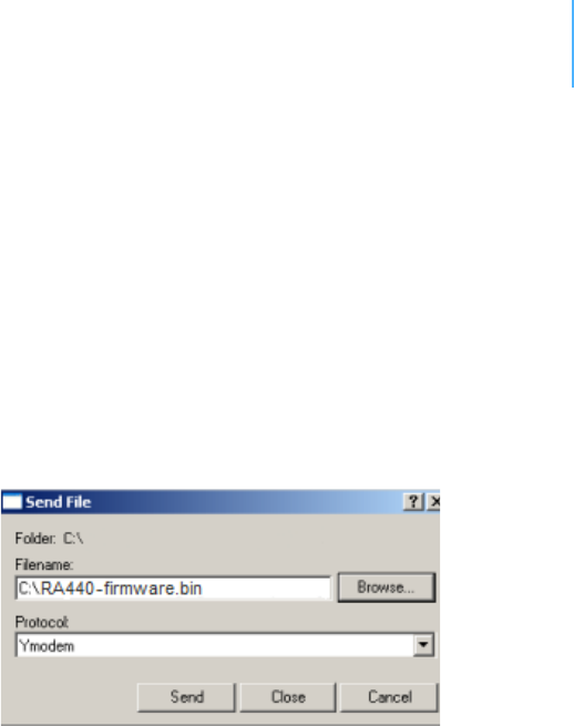
10. From the hyperterminal window’s menu bar, select TransferSend
File to display the dialog shown in Figure 14.
Note: You must start the image upload within 60 seconds or a timeout will
occur.
11. Browse to and select the firmware image.
12. Select the Ymodem Protocol and click Send.
Figure 14. Dialog to Upload Firmware Image
13. To start the new firmware, enter the following command:
firmware
Serialcommunicationprotocol
This protocol is based on a master sending commands and a node
answering. The whole communication is conducted in plain ASCII, as
strings, and numbers are represented in decimal format. All
commands are terminated with a CR/LF combination. All responses
(answers) are terminated with the # character.
Generalformatofacommand
The commands have the following format:
ID Command Param1 Param2 ... ParamN
•ID is the destination device. If you include an ID as part of a
command, the node checks whether ID=ownID. If it does, the
node executes the command on itself. If the ID is not the node’s
ID, the node executes the command on a remote device, if such
an ID exists. If the ID is missing, this implies that the command
is addressed locally.
Note: Not all the commands can be relayed remotely.

CHAPTER3
Usingterminalcommands
30
•Command is the command proper, which can be composed of a
variable string of characters (for example, SLOT). Each node can
implement a set of commands depending on the functionality of
the node itself. However, as a minimum requirement, a node
recognizes the CMDS command, which returns a list with the
commands accepted by the node.
•Param1 Param2 ... ParamN represent the parameters, which
are command dependent. If you type no parameters when you
issue a command, it is the equivalent of querying for information
(the GET version of a command). If you type parameters, you
are issuing the SET version of a command and are setting the
command to the parameters you typed.
Generalformatofananswer
The answers have the following format:
ID Command Result1 Result2 ... ResultN ErrResult #
•ID is the answering device. If a command was further routed, it is
the ID of the end device. The answer must always contain the ID
on return.
•Command is the string representing the original command. It is
supplied so that a master can distinguish between the answers it
is waiting for, and out-of-band notifications (which may come, for
example, over the radio port of a node). As with the ID, the
command name must always be supplied.
•Result1 Result2 ... ResultN are the result values returned
by the remote node. If the ErrResult is not zero, all other
possible characters and/or strings until the end of the line might
be ignored.
•ErrResult shows whether the command was successfully
executed. If this value is 0, the command was successfully
executed. If this value is other than 0, the command failed. The
number may further indicate the error type. (See also “Returned
errors list” on page 50.)
The answer string may contain any number of spaces or CR/LF
characters between its components. However, after the terminator
(#), no other characters are allowed.
Usingterminalcommands
The RA440 remote wireless modem firmware is based on the firmware
used in the Series 4 RTUs. Therefore the RA440's commands are very
similar to the Series 4 commands.
Note: As mentioned before, the RA440 incorporates an A440 as the Adcon
Telemetry Network modem. For directing commands to the
incorporated A440 you must prefix the A440's ID in front of the
command.

CHAPTER3
Usingterminalcommands
31
Following is a list of available commands and an explanation of their
use.
Note: You can type uppercase or lowercase characters because the
commands are not case sensitive.
A440TMOUT
AVAILABLE FOR RA440
DESCRIPTION Sets a timeout, after which the RA440 will turn on the A440, if no
communication to the device occurs and a command for the unit is
pending.
PARAMETERS The time in seconds.
REMARKS SET/GET.
RETURNS Error code or the seconds set.
REMOTE Yes.
EXAMPLE # A440TMOUT 60
441 A440TMOUT 0
#
# A440TMOUT
441 A440TMOUT 60 0
#
B
AVAILABLE FOR A440
DESCRIPTION Sends a broadcast frame.
PARAMETERS None.
REMARKS After the device has sent the broadcast frame, it will listen for
answers. All valid answers will be listed with their IDs.
RETURNS A data block.
REMOTE Yes. A device getting this frame would have to wait for a random time
(2 to 10 seconds) before performing the actual broadcast; if no
terminal is active, no results will be listed. A list of stations heard, with
their RF levels, will be updated in the memory and will be available
when the BLST command is issued.
EXAMPLE # B 442
B0
# 42340 BA 0
# 34781 BA 0
#

CHAPTER3
Usingterminalcommands
32
BLST
AVAILABLE FOR A440
DESCRIPTION Lists the stations heard after the last broadcast command was issued.
PARAMETERS None.
REMARKS GET only.
RETURNS The date and time the broadcast was performed, the number of
stations heard, and a list with the heard stations’ IDs and their
respective RF levels.
REMOTE Yes. The remote version will list only the first nine stations heard.
EXAMPLE # BLST
442 BLST 08/05/2009 15:56:04 4
42340 235 255
34781 255 255
#
CMDS
AVAILABLE FOR RA440
A440
DESCRIPTION Returns a list of supported commands.
PARAMETERS None.
REMARKS GET only.
RETURNS A list of strings separated by spaces.
REMOTE Yes.
EXAMPLE # cmds
441 cmds A440TMOUT A440X ANLG AUTH CALC DPE DYNSLOT FDEV
GPRSAPNPW GPRSAPNSERV GPRSAPNUN GPRSCONN GPRSCONNADDR
GPRSCONNALIGN GPRSCONNINT GPRSDNS GPRSPING GPRSSE CRET
GPRSTMOUT GSMDIALIN GSMOPER GSMPIN GSMPOWERSAVE GSMPUK
GSMROAM GSMSQ GSMSTA T GSMTMOUT ID INFO LVA PMP PORT SBAT
SLOT SST TIME TYPE VER XCONF XDATA XIMME 0
#
DATA
AVAILABLE FOR A440
DESCRIPTION Retrieves data frames from RTUs earlier than Series 4.
PARAMETERS See the manual for the appropriate pre Series 4 RTU.

CHAPTER3
Usingterminalcommands
33
REMARKS Remote only. Support for pre Series 4 RTUs.
RETURNS A pre Series 4 data frame.
REMOTE Yes.
EXAMPLE # 9999 DATA
9999 DATA
13 9 1999 19 26 36 21 37 255 255 79 0 0 0 0 87 148 149 15 0
0 0 0 0 0 0 0 0 3148 0
#
# 9999 DATA 9999 30/9/1999 14:50:00
9999 DATA 30 9 1999 14 54 55 21 37 255 255 77 0 0 0 0 89
156 126 20 0 0 0 0 0 0 0 0 0 3197 0
#
DATASDI
AVAILABLE FOR A440
DESCRIPTION Retrieves SDI-12 data frames from RTUs earlier than Series 4.
PARAMETERS See the manual for the appropriate pre Series 4 RTU.
REMARKS Remote only. Support for pre Series 4 RTUs.
RETURNS A pre Series 4 data frame.
REMOTE Yes.
EXAMPLE # 12800 DATASDI
12800 DATASDI
16 5 2003 20 14 49 44 60 255 255 127 87 9 0 9 3 0 0
74.379401 3 0 1 68.117003 3 0 2 58.832397 3 0 3 51.611795 3
0 4 38.346400 3 0 5 19.800799 3 0 6 14.895999 3 0 7 3.553500
3 0 8 0.037200 2953 0
#
FDEV
AVAILABLE FOR RA440
DESCRIPTION Formats the internal memory (might destroy all the data).
0 WARNING The chip configuration setting (first parameter of the command)
depends on the current hardware version and must not be altered.
Please contact our support team for further information.
PARAMETERS If the parameters are missing, the command will show the current
settings. To format the internal memory (all data will be lost) with the
current settings, use 0 as the first parameter. The storage
organization (the index size only), can be optimized for your specific
application. The first parameter for this command is the chip

CHAPTER3
Usingterminalcommands
34
configuration and second parameter is the index size. The RA440
factory setting is:
•1st parameter: 1
• 2nd parameter: 384
REMARKS GET/SET.
RETURNS Current memory setting.
REMOTE Yes.
EXAMPLE # 441 FDEV
441 FDEV 1 16+0 64..1024 384/383 9216/9192 0
#
# 441 FDEV 1 384
441 FDEV 0
#
FREQ
0 CAUTION Do not change the frequency of your device without reason. Apart
from the fact that it might not communicate in the network anymore,
you might also violate the applicable radiocommunications laws in
your country. Depending on the destination country, some models
may also return an error message.
AVAILABLE FOR A440
DESCRIPTION Sets/returns the operating frequency.
PARAMETERS The operating frequency and step (Hz), or none in the GET version.
REMARKS GET/SET.
RETURNS The actual frequency and step, in Hz.
REMOTE Yes, SET only.
EXAMPLE # FREQ 433925000 25000
442 FREQ 0
# FREQ
442 FREQ 433925000 25000 0
#
GPRSAPNPW
AVAILABLE FOR RA440
DESCRIPTION Sets/returns the GPRS operator network’s access point password.
PARAMETERS None or the GPRS operator network’s access point password.
REMARKS GET/SET.

CHAPTER3
Usingterminalcommands
35
RETURNS If no parameter was entered, the current access point password is
returned. Otherwise the error code of the operation is returned.
REMOTE No.
EXAMPLE # GPRSAPNPW "t-mobile"
441 GPRSAPNPW 0
#
# GPRSAPNPW
441 GPRSAPNPW "t-mobile" 0
#
GPRSAPNSERV
AVAILABLE FOR RA440
DESCRIPTION Sets/returns the GPRS operator network’s access point name.
PARAMETERS None or the GPRS operator network’s access point name.
REMARKS GET/SET.
RETURNS If no parameter was entered, the current access point name is
returned. Otherwise the error code of the operation is returned.
REMOTE No.
EXAMPLE # GPRSAPNSERV "apnserv.t-mobile.at"
441 GPRSAPNSERV 0
#
# GPRSAPNSERV
441 GPRSAPNSERV "apnserv.t-mobile.at" 0
#
GPRSAPNUN
AVAILABLE FOR A440
DESCRIPTION Sets/returns the GPRS operator network’s access point user name.
PARAMETERS None or the GPRS operator network’s access point user name.
REMARKS GET/SET.
RETURNS If no parameter was entered, the current access point user name is
returned. Otherwise the error code of the operation is returned.
REMOTE No.
EXAMPLE # GPRSAPNUN "t-mobile"
441 GPRSAPNUN 0
#
# GPRSAPNUN

CHAPTER3
Usingterminalcommands
36
441 GPRSAPNUN "t-mobile" 0
#
GPRSCONN
AVAILABLE FOR RA440
DESCRIPTION Enable/Disables the GPRS functionality.
PARAMETERS •None
• 1 enables GPRS function.
• 0 disables GPRS function.
REMARKS SET only.
RETURNS The error code.
REMOTE No.
EXAMPLE # GPRSCONN
441 GPRSCONN 0
#
GPRSCONNADDR
AVAILABLE FOR RA440
DESCRIPTION Sets/returns the IP address and the port of the A850 Telemetry
Gateway.
PARAMETERS None or the IP address and the port of the A850 Gateway and
optionally the connection preference. The user may specify by
entering a new IP address and port if the new connection is primary or
a secondary is used. If the index is left, the connection type will be
taken as primary.
REMARKS GET/SET.
RETURNS If no parameter was entered, the A850’s IP and Port is returned.
Otherwise the error code of the operation is returned.
REMOTE No.
EXAMPLE # GPRSCONNADDR "172.17.5.99" 81
441 GPRSCONNADDR 0
#
# GPRSCONNADDR
441 GPRSCONNADDR
172.17.5.99 81 0
0
#

CHAPTER3
Usingterminalcommands
37
GPRSCONNALIGN
AVAILABLE FOR RA440
DESCRIPTION Sets/returns the connection setup alignment point, in seconds, from
0:00 (UTC). This value and GPRSCONNINT determine when the device
checks the connection to the A850 Telemetry Gateway and eventually
reestablishes it.
Note: A value of 3600 seconds means that the alignment point for the first
connection check with the A850 Telemetry Gateway is at 1:00 (UTC)
in the morning.
PARAMETERS The connection setup alignment point in time in seconds. The range is
limited to 0 to 4294967295.
REMARKS GET/SET.
RETURNS The current value.
REMOTE Yes.
EXAMPLE # GPRSCONNALIGN 1800
441 GPRSCONNALIGN 0
#
# GPRSCONNALIGN
441 GPRSCONNALIGN 1800 0
#
GPRSCONNINT
AVAILABLE FOR RA440
DESCRIPTION Sets/returns the connection setup interval in seconds. This value and
GPRSCONNALIGN determine when the device checks the connection
to the A850 Telemetry Gateway and eventually reestablishes it.
Note: A value of 3600 seconds means that the connection to the A850
Telemetry Gateway will be checked every hour.
PARAMETERS The connection setup interval in seconds. The range is limited to 0 to
86399.
REMARKS GET/SET.
RETURNS The current value.
REMOTE Yes.
EXAMPLE # GPRSCONNINT 900
441 GPRSCONNINT 0
#
# GPRSCONNINT

CHAPTER3
Usingterminalcommands
38
441 GPRSCONNINT 900 0
#
GPRSDNS
AVAILABLE FOR RA440
DESCRIPTION Sets/returns the IP address of the GPRS network operator’s DNS
servers.
Note: You can enter two different DNS servers that are indexed. If the first
DNS server is unreachable, the second one will be contacted.
PARAMETERS None or the IP address followed by the index of the DNS server.
REMARKS GET/SET.
RETURNS If no parameter was entered, the set DNS server IPs are returned.
Otherwise the error code of the operation is shown.
REMOTE No.
EXAMPLE # GPRSDNS "172.17.4.89" 0
441 GPRSDNS 0
#
# GPRSDNS "172.17.4.90" 1
441 GPRSDNS 0
#
# GPRSDNS
441 GPRSDNS
0 172.17.4.89
1 172.17.4.90
0
#
GPRSPING
AVAILABLE FOR RA440
DESCRIPTION Pins a specific host.
Note: You can enter two different DNS servers that are indexed. If the first
DNS server is unreachable, the second one will be contacted.
PARAMETERS The hosts IP the ping count (Range:1 -10), and the ping timeout
(Range: 1 -10).
REMARKS SET only.
The command works only if no GPRS connection has been established.
RETURNS Nothing if failed or the ping number, IP, and response time.
REMOTE No.

CHAPTER3
Usingterminalcommands
39
EXAMPLE # GPRSPING "172.17.5.99" 3 5
441 GPRSPING
1: 172.17.5.99 833ms
2: 172.17.5.99 445ms
3: 172.17.5.99 398ms
0
#
GPRSSECRET
AVAILABLE FOR RA440
DESCRIPTION Sets/returns the secret value. This secret is used to authenticate the
device at the A850 Telemetry Gateway.
PARAMETERS The chosen secret. The range is limited to 0 to 4294967295.
REMARKS GET/SET.
RETURNS The current value.
REMOTE No.
EXAMPLE # GPRSSECRET 441441
441 GPRSSECRET 0
#
# GPRSSECRET
441 GPRSSECRET 441441 0
#
GPRSTMOUT
AVAILABLE FOR RA440
DESCRIPTION Sets/returns the timeout in seconds, after which the device should
assume that the connection to the A850 Telemetry Gateway is broken.
Note: Adcon recommends that you set the GPRSTMOUT to a value that is at
least twice that of GPRSCONNINT.
PARAMETERS The timeout in seconds. The range is limited from 0 to 4294967295.
REMARKS GET/SET.
RETURNS The current value.
REMOTE Yes.
EXAMPLE # GPRSTMOUT 3600
441 GPRSTMOUT 0
#
# GPRSTMOUT
441 GPRSTMOUT 3600 0
#

CHAPTER3
Usingterminalcommands
40
GSMOPER
AVAILABLE FOR RA440
DESCRIPTION Returns the currently used cellular network operator.
PARAMETERS None.
REMARKS GET only.
The command works only if no GPRS connection has been established.
If a GPRS connection has been established, use GSMSTAT instead.
RETURNS The current network operator.
REMOTE No.
EXAMPLE # GSMOPER
441 GSMOPER "T-mobile Austria" 0
#
GSMPIN
AVAILABLE FOR RA440
DESCRIPTION Sets the PIN-code of the SIM-card or returns the SIM-card unlock
state.
PARAMETERS The new PIN-code, or none (for SIM-card check).
REMARKS GET/SET.
RETURNS If no parameter was entered following messages may get displayed:
“Ready”
The used PIN code was accepted.
“PIN required”
No or false PIN was entered. Reenter the correct PIN-code.
“PUK required”
The false PIN was entered too often. The module has locked the SIM-
card. To open the lock. enter the PUK-code of the SIM-card. If the new
PIN-code was entered as a parameter of the command, returns the
error code.
REMOTE No.
EXAMPLE # GSMPIN
441 GSMPIN Ready 0
#
# GSMPIN 1234
441 GSMPIN 0
#

CHAPTER3
Usingterminalcommands
41
GSMPUK
AVAILABLE FOR RA440
DESCRIPTION Sets a new PIN-code for the SIM-card or returns the SIM-card unlock
state.
PARAMETERS The PUK-code and the new PIN-code, or none (for SIM-card check).
REMARKS GET/SET.
RETURNS Refer to the command GSMPIN.
REMOTE No.
EXAMPLE # GSMPUK
441 GSMPUK Ready 0
#
# GSMPUK 56789 1234
441 GSMPUK 0
#
GSMSQ
AVAILABLE FOR RA440
DESCRIPTION Returns the signal quality and the bit error rate of the used cellular
network.
PARAMETERS None.
REMARKS GET only. The command works only if no GPRS connection has been
established. If a GPRS connection has been established, use GSMSTAT
instead.
RETURNS The signal quality parameter.
REMOTE No.
EXAMPLE # GSMSQ
441 GSMSQ 31 99 0
#
GSMSTAT
AVAILABLE FOR RA440
DESCRIPTION Displays the status of the GSM module.
PARAMETERS None.
REMARKS GET only.
RETURNS A list of various status information of the current module state.

CHAPTER3
Usingterminalcommands
42
REMOTE Yes.
EXAMPLE # gsmstat
441 gsmstat
Power supply on: yes
DTR on: yes
DCD on: no
RI on: no
RTS on: yes
CTS on: no
Modem on: yes
Modem present: yes
Modem initialized: yes
SIM card present: yes
PIN required: yes
PIN accepted: yes
PIN count: 3
PUK required: no
GSM network: registered
Operator: T-mobile Austria
Signal quality: 31 99
Phone call: no
GPRS network: registered
IP address: no
TCP connection: no
0
#
ID
AVAILABLE FOR RA440
A440
DESCRIPTION Sets/returns the node’s ID.
PARAMETERS The node ID.
REMARKS GET/SET.
RETURNS The node ID.
REMOTE Yes, SET only.
EXAMPLE # ID 445
441 ID 0
#
# ID
445 ID 445 0
#

CHAPTER3
Usingterminalcommands
43
INFO
AVAILABLE FOR RA440
A440
DESCRIPTION Returns various status information.
PARAMETERS None.
REMARKS GET only.
RETURNS A list of a device’s internal variables:
ID INFO rf_in rf_out date time ver clk stack cop batt temp
days_uptime hr:min_uptime rssi pmp_low pmp_high type slot
samples po err_level
#
The formats for the above parameters are as follows:
•rf_in and rf_out as a decimal.
•date as dd/mm/yyyy.
•time as hh:mm:ss.
•ver as x.x.
•clk,stack, and cop as decimal. They represent internal
housekeeping parameters: the RA440/A440 uses cop to number
watchdog occurrences, but clk and stack are currently undefined.
•batt as battery level, using the standard voltage conversion
equation (0 is 0 volts, 255 is 20 volts).
Note: This parameter has no relevance for the A440 (normally shows 0).
•temp as internal temperature in the housing, which is device
dependent. The precision of the sensing element is low (±2°C),
but it is sufficient for battery power management (charge/
discharge). To compute the actual value (in °C), the following
equation must be used:
Note: This parameter has no relevance for the A440 (normally shows 0).
•days_uptime in days; with hr:min_uptime, it represents the
amount of time the device is up without a reset or watchdog.
•hr:min_uptime in hours:minutes format.
•rssi as decimal; it is the programmed value with the RSSI
command.
Note: This parameter has no relevance for the RA440 (normally shows 0).
•pmp_low and pmp_high are the programmed values with the PMP
command. However, because they have no relevance for the
A440, they will always return zero values.
Temp qC>@
internalTemp 400
255
------------------------------------------------- 6 8–=

CHAPTER3
Usingterminalcommands
44
•type is used to represent the device type. The following types are
assigned currently:
— 0 for A730MD
— 1 for A720
— 2 for A730SD
— 3 for A720B
— 4 for A733
— 5 for A723
— 6 for A440
— 7 for A733 GSM
— 8 for A731
— 9 for A732
— 10 for A740
— 11 for A740 GSM
— 12 for A724
— 15 for A723_Series 4
— 16 for A724_Series 4
— 21 for A753GSM
— 24 fir RA440
•slot and samples are the actual values programmed by means of
the SLOT command.
Note: The “slot” parameter has no relevance for the A440. The “samples”
parameter has no relevance for RA440 or the A440 (normally they
show 0).
• po is the relative output power of the device.
Note: This parameter has no relevance for the RA440 (normally shows 0).
•err_level is the error value; 0 means no error.
REMOTE Yes, GET only.
EXAMPLE # 441 info
441 info 0 31 01/01/1970 00:00:00 1.2 0 0 0 83 60 0 00:40 0
65 72 24 900 0 0 0
#
PMP
AVAILABLE FOR RA440
DESCRIPTION Sets/returns the node’s Power Management Parameters (switches the
battery charge on/off).
PARAMETERS The lower (switch on) and the higher limit (switch off), both in volts x
10. Standard Values are 65 (for 6.5 volts) for switch on and 72 (for
7.2 volts) for switch off, for a standard 6.2 volt NiMH battery. From
these values, other thresholds are internally computed.
REMARKS GET/SET.

CHAPTER3
Usingterminalcommands
45
RETURNS The lower (switch on) and the higher limit (switch odd), both in volts x
10.
REMOTE Yes, SET only.
EXAMPLE # PMP 65 72
441 PMP 0
#
# PMP
441 PMP 65 72 0
#
ROUTE
AVAILABLE FOR A440
DESCRIPTION Sets/returns the routing information of a device.
PARAMETERS None, or a route (with destination) containing up to eight
intermediaries. When only the destination ID is given, the route for
this device is deleted.
REMARKS GET/SET.
RETURNS The command’s success or error code and the route table.
REMOTE Yes, but only to an A440 attached to an RA440.
EXAMPLE For MFS:
# ROUTE 445 43
442 ROUTE 0
#
# ROUTE
442 ROUTE 445 43 0
#
RSSI
AVAILABLE FOR A440
DESCRIPTION Sets/returns the Relative Signal Strength Indicator threshold at which
the RF receiver must wake up.
PARAMETERS The threshold value. For the A440, it can take values from 0 to 255; it
is typically factory set to 50.
REMARKS GET/SET.
RETURNS The instant RSSI value and the programmed threshold.
REMOTE No.

CHAPTER3
Usingterminalcommands
46
EXAMPLE # RSSI 50
442 RSSI 0
#
# RSSI
41239 RSSI 34 50 0
#
Note: The values of the RSSI threshold are arbitrary and have no units.
RX
AVAILABLE FOR A440
DESCRIPTION Switches the unit to permanent receive mode (for tuning purposes).
PARAMETERS None.
REMARKS The system stops, and exits the command only when a key is pressed.
This command returns no message.
RETURNS Nothing.
REMOTE No.
EXAMPLE # 442 RX
442 RX 0
#
TIME
AVAILABLE FOR RA440
A440
DESCRIPTION Sets/returns the real time clock.
PARAMETERS The actual time, or none in the GET version.
REMARKS GET/SET.
RETURNS The actual time as dd/mm/yyyy hh:mm:ss.
REMOTE Yes.
EXAMPLE # TIME 20/06/2009 12:10:10
441 TIME 0
#
# TIME
441 TIME 20/06/2009 12:10:10 0
#
TX
AVAILABLE FOR A440

CHAPTER3
Usingterminalcommands
47
DESCRIPTION Switches the unit to transmit mode (for tuning purposes).
PARAMETERS • None (sends an unmodulated carrier)
• 1 (sends a 1 kHz modulated carrier)
• 0 (sends a 2 kHz modulated carrier)
• 5 (sends a mixed 1 + 2 kHz modulated carrier)
REMARKS The system stops, and exits the command only when a key is pressed.
This command returns no message.
RETURNS Nothing.
REMOTE No.
EXAMPLE # TX
442 TX 0
#
# TX 1
442 TX 0
#
# TX 5
442 TX 0
#
TYPE
AVAILABLE FOR RA440
A440
DESCRIPTION Requests the hardware type information of the device.
PARAMETERS None.
REMARKS GET only.
RETURNS The hardware type.
REMOTE Yes.
EXAMPLE # TYPE
441 TYPE RA440 0
#
VER
AVAILABLE FOR RA440
A440
DESCRIPTION Requests the firmware version of the device.
PARAMETERS None.
REMARKS GET only.

CHAPTER3
Usingterminalcommands
48
RETURNS The current version.
REMOTE Yes.
EXAMPLE # VER
441 VER 1.3.2 0
#
VERB
AVAILABLE FOR RA440
A440
DESCRIPTION Sets the verbosity level of the device. This command is used for
debugging only.
0 WARNING The device will consume a lot more power when the verbosity level is
greater than 0. This could discharge your battery and/or prevent
proper operation.
PARAMETERS A verbosity level (0...255).
REMARKS SET only.
RETURNS Error code.
REMOTE No.
EXAMPLE # VERB 1
442 VERB 0
VERB 1 # src=43 dest=9002 type=? src=43 dest=9002 type=?
# VERB 0
442 VERB 0
#
XDATA
AVAILABLE FOR RA440
DESCRIPTION This command requests data for a list of logical channels for given
timestamps.
PARAMETERS XDATA requires a lot of parameters for specifying what to retrieve.
Please consult the A740 User Manual for detailed explanation of this
command. The output of the command is not intended to be human
readable.
REMARKS GET only. (This is a data retrieval command, local as well as remote.)
RETURNS A data block.
REMOTE Yes, for a GET, but only one frame at a time.

CHAPTER3
Usingterminalcommands
49
EXAMPLE # 441 XDATA 0 8 0 255 1 0
441 XDATA 0 199 0x18 0x4A4211BC 1 0 0xF6 :8F0384645739
0
#
XIMME
AVAILABLE FOR RA440
DESCRIPTION Samples all inputs and immediately returns the sampled data.
PARAMETERS First parameter specifies the sample mode, which has to be 2 for raw
data. The second parameter sets the maximum packet size. If you
specify the third parameter, you can select a specific input connector.
Note: Only sample mode 2 is supported on the RA440.
REMARKS GET only. The command needs a specific delay to execute. The delay
depends on the setting at the SST command.
RETURNS A data block of logical channel, raw adc and counter values.
ID XIMME
int_chnl int_dig bat temp ext_volt 0
{chnl_nr dig_byte raw_cabl1 raw_cabl2 raw_cabl3 cnt}
The format of the above response is as following:
•int_chnl is the logical channel number of the internal connector
(always 0).
•int_byte is a byte (0 to 255) and shows whether the SOLAR CELL
is connected and if the charger is activated.
•bat is the measured battery value (for details see the INFO
command).
•temp is the measured temperature value (for details see the
INFO command).
•ext_volt is the external DC INPUT level using the following
conversion:
•chnl_nr is the logical channel of the shown connector:
• 1 — IO-A
• 2 — IO-B
• 3 — IO-C
• 4 — IO-D
The RA440 has no external sensor connectors. Therefore the values of
the two batteries are shown on raw_cabl1 of IO-A and IO-B.
•dig_byte is the digital status byte.
•raw_cabl1 is the raw value read on cabling 1 by the analog-digital
converter.
DCInput Volts>@
ext_volt
255
------------------- 27.5u=

CHAPTER3
Returnederrorslist
50
•raw_cabl2 is the raw value read on cabling 2 by the analog-digital
converter.
•raw_cabl3 is the raw value read on cabling 3 by the analog-digital
converter.
•cnt is the current value of the counter.
Note: The braces, {...}, show that this part may repeat, depending on the
device type. For an RA440 the output will show the logical channels 0,
1, and 2.
REMOTE Yes.
EXAMPLE # ximme 2
441 ximme
0 129 0 54 0 0
1 1 22272 0 0 0
2 1 22208 0 0 0
0
#
Returnederrorslist
Following are error messages you might get.
Commandlineinterpreter
• 1 — nonexistent command
• 2 — command line buffer overflow (input line too long)
• 3 — internal error
• 4 — reserved
• 5 — missing or false parameters in command
• 6 — operation not implemented
• 7 — remote operation not allowed
• 8 — invalid IMEI Number
• 9 — command not supported in this configuration
Devicedescriptorandstoragehandler
• 10 — device not found (attempt to perform a command on a
nonexistent device)
• 11 — device already exists
• 12 — reserved
• 13 — no more space for descriptors (too many devices)
• 14 — no more records for the specified device
• 15 — temporary communication break, no more data (the last
request was not successful)
• 16 — time-out (the handler blocked or is busy)
• 17 — internal error

CHAPTER3
Performingconnectivitychecks
51
• 18 — attempt to insert a reserved device ID number (0 or 65535)
Realtimeclock
• 20 — incorrect time supplied (no conversion to time_t was
possible)
Radiointerface(includingGSM/GPRSModem)
• 30 — error at receive (CRC, etc.)
• 31 — unexpected frame received
• 32 — wrong length
• 33 — reserved
• 34 — reserved
• 35 — time-out (remote device not responding)
• 36 — receiver busy (for example, currently performing a polling
series)
• 37 — time stamp of a frame is too far in the future
• 38 — general modem error
• 39 — “unknown modem” error
Notifications
• 40 — request to read a notification when no notification is
pending
Performingconnectivitychecks
If you want to insert an RA440 Wireless Radio Modem into an existing
Adcon radio network, you should consider performing connectivity
checks before finishing installation of the device. Connectivity checks
are similar to the RTU connection checks. Before performing these
checks, you must have following items prepared:
• the A440 Serial number (printed on the type plate of the RA440)
• a serial communication cable (item number 200.720.540 from
your Adcon distributor)
The following instructions show you how to perform the connectivity
check:
1. After you check the connection to the A850 Telemetry Gateway
using the LED tool, disconnect the LED tool. A few seconds later,
connect your serial communication cable to the SOLAR CELL
connector.
2. Make a broadcast by entering the <A440_ID> B command, where
A440_ID is the serial number of your A440.
3. Wait at least 15 seconds.

CHAPTER3
Performingconnectivitychecks
52
4. Enter the <A440_ID> BLST command and wait for the response,
which shows you the heard responses of the broadcast sent by
the RA440.
5. Pick the RTUs that will communicate with the RA440. Check every
RA440-RTU connection by entering the <RTU_ID> INFO
command, where RTU_ID is the serial number of the RTU picked
from the broadcast response list.
6. Check the radio link quality of the connection displayed at rf_in
and rf_out at the ping response. For a good link quality to a
Series 3 RTU, the value must be at least 200. See “INFO” on
page 43 to pick the RF indicators.
7. If all of your ping commands respond with a good radio link
quality, the proper function of the RA440 at this position is
ensured. If one or more radio links did not pass the threshold,
reposition your RA440 or route the communication via other,
nearby, radio units.
Example:
# 442 B
# 442 BLST
442 BLST 08/05/2009 15:56:04 4
42340 235 255
34781 255 255
# 42340 INFO
42340 INFO 235 255 08/05/2009 15:57:35 3.3 0 0 0 83 60 0
00:40 0 65 72 4 900 0 0 0
# 34781 INFO
34781 INFO 255 255 08/05/2009 15:58:24 3.3 0 0 0 83 60 0
00:40 0 65 72 4 900 0 0 0
#

53
Appendix.Specifications
The RA440 remote wireless modem was intended to fulfill the
specification of the ETSI 300 220, Class I, Subclasses a and b, but
other national norms are similar to this (for example, the CFR 47, Part
90, Subpart J). Table 3 shows the main operational parameters of the
RA440.
Table 3. Operational Parameters
Parameter Min Type Max Unit
Common
Supply Voltage (internal battery) +5.6 +10 V
Supply Voltage (external battery) +11.5a+18 V
Operation Temperature -20 +55 °C
Relative Humidity 10 99 % rH
Class Protection IP65
Data Rate (GSM/GPRS modem - GPRS mode) multislot,
class 10
Data Rate (ISM modem) 1000 1500b2000 kbps
Operating Frequency (low-band version)c432 450 MHz

APPENDIX 54
Operating Frequency (high-band version)c450 470 MHz
Frequency Stability
(-20 to +50 °C / -4 to +122 °F)
±1.5 kHz
Frequency Stability
(-30 to +60 °C / -22 to +140 °F)
±2.5 kHz
Receive Mode
Sensitivity (12 db S/S+N) -118 dBm
Image Frequency Attenuation
(first IF = 45 MHz)
-70 dB
Local Oscillator Leakage 2 nW
Adjacent Channel Attenuation
(12.5 kHz mode)
-57 dB
RSSI Dynamic 90 dB
Operating Current (including onboard
microcontroller)
32 mA
Receive Mode (GPRS modem)
Sensitivity EGSM 900 / GSM850 -102 dBm
Sensitivity EGSM 1800 / GSM1900 -102 dBm
Operating Current (DRX mode 9) 3.5 mA
Transmit Mode (all measurements made on a 50 Ohm resistive load)
Output Power +27 dBm
Spurious Radiation 200 nW
Adjacent Channel Power (20 kHz mode) -34 dBm
Occupied Bandwidth (20 kHz version) 15 kHz
Operating Current (including onboard
microcontroller)
600 mA
Transmit Mode (GPRS modem)
Output Power EGSM 900 / GSM850 33dBm
(± 2dB)
Table 3. Operational Parameters (Continued)
Parameter Min Type Max Unit

APPENDIX 55
Output Power EGSM 1800 / GSM1900 30dBm
(± 2dB)
Operating Current
(avg. GPRS Class 10 - 2TX / 3RX)
450 mA
Peak Current (at TX burst) 2.0 A
SIM Interface
Interface Type GSM 11.11 & GSM 11.12
SIM Card Voltage 1.8 / 3 V
a. This value relates to the voltage needed to enable the DC INPUT connector circuit. After acti-
vation the voltage may drop to approximately 9.5 volts minimum before the DC INPUT circuit
will shut down the connector to protect a connected rechargeable battery from deep dis-
charge.
b. Data rate is content dependent.
c. This parameter represents the tuning range; the switching range may be limited in the soft-
ware to a narrower space (even to the extent of a single channel).
Table 3. Operational Parameters (Continued)
Parameter Min Type Max Unit

56
Index
A
A440,commandsto,30
A440TMOUTcommand,31
A850gateway,5,8
about
LED,19
RA440,5
adaptability,5
answerformat,30
B
Bcommand,31
battery
changing,21
description,19
operation,20
usage,6
BLSTcommand,32
bootingRA440,25
bootloadermode,25
C
celluse,GSM,10
changingthebattery,21
CMDScommand,32
commandlineinterpretererrors,50
commands
A440TMOUT,31
answerformat,30
B,31
BLST,32
CMDS,32
DATA,32
DATASDI,33
FDEV,33
FREQ,34
generalformat,29
GPRSAPNPW,34
GPRSAPNSERV,35
GPRSAPNUN,35
GPRSCONN,36
GPRSCONNADDR,36
GPRSCONNALIGN,37
GPRSCONNINT,37
GPRSDNS,38
GPRSPING,38

INDEX 57
GPRSSECRET,39
GPRSTMOUT,39
GSMOPER,40
GSMPIN,40
GSMPUK,41
GSMSQ,41
GSMSTAT,41
ID,42
INFO,43
PMP,44
ROUTE,45
RSSI,45
RX,46
TIME,46
totheA440,30
TX,46
TYPE,47
VER,47
VERB,48
XDATA,48
XIMME,49
communicatingwithRA440,25
compliancestatement,6
configuring
GPRSconnection,15
GPRSparameters,14
TCPparameters,15
connectivitycheck,17
connector
DCinput,24
solarcell,23
conventions,document,6
D
DATAcommand,32
DATASDIcommand,33
DCinputconnector,24
definitions
connectors,22
LED,17
masternode,22
miserystate,19
RA440,5
slavenode,22
device
descriptors,50
operationtime,20
documentconventions,6
E
errors
commandlineinterpreter,50
devicedescriptorsandstoragehandler,50
notifications,51
radiointerface,51
realtimeclock,51
F
FCCcompliance,6
FDEVcommand,33
firewallwithA850gateway,15
firmwaremode,26
formatofcommandsandanswers,29
FREQcommand,34
frequencyrange,5
G
GPRSparameters,14
GPRSAPNPWcommand,34
GPRSAPNSERVcommand,35
GPRSAPNUNcommand,35
GPRSCONNcommand,36
GPRSCONNADDRcommand,36
GPRSCONNALIGNcommand,37
GPRSCONNINTcommand,37
GPRSDNScommand,38
GPRSPINGcommand,38
GPRSSECRETcommand,39
GPRSTMOUTcommand,39
GSMcellularnetwork,10
GSMOPERcommand,40
GSMPINcommand,40
GSMPUKcommand,41
GSMSQcommand,41

INDEX 58
GSMSTATcommand,41
I
IDcommand,42
INFOcommand,43
insertingSIMcard,12
installRA440,17
installationissues,9
internalbattery,19
L
LED
definition,17
usage,19
M
maintainingtheRA440,19
miserystate,19
N
notifications,51
O
operationalmodes,25
operationalparameters,53
P
packagecontents,8
parameters,operational,53
performingaconnectivitycheck,17
PMPcommand,44
powerconsumption,6
prompt
bootloadermode,26
firmwaremode,26
R
RA440
adaptability,5
booting,25
communicatingwith,25
compliancestatement,6
GPRSconnectionsettings,15
installing,17
mainenance,19
miserystate,19
packagecontents,8
SIMcard,10
specifications,53
upgradingfirmware,27
radiointerfaceerrors,51
realtimeclockerrors,51
restrictionsforinstallation,9
ROUTEcommand,45
RSSIcommand,45
ruggedized,6
RXcommand,46
S
SIMcard,10
solarcellconnector,23
specialformattingindocument,6
specifications,53
storagehandlererrors,50
T
TCPparameters,15
TIMEcommand,46
TXcommand,46
TYPEcommand,47
U
upgradingRA440firmware,27
usingLEDforconnectivitycheck,17
V
VERcommand,47
VERBcommand,48
X
XDATAcommand,48
XIMMEcommand,49