Ott Hydromet OTTRLS Radar Level Sensor User Manual Anleitung RLS Zul EN
Ott Hydromet GmbH Radar Level Sensor Anleitung RLS Zul EN
UserManual.wiki
>
Ott Hydromet
>
OTTRLS User Manual
User Manual
Navigation menu
Upload a User Manual
Namespaces
Wiki Guide
HTML
PDF
Info
Views
User Manual
Discussion / Help
Navigation

![ᮣSlave address SDI-12 bus address. Each slave address may onlybe allocated once to an SDI-12 bus line. (check-ing/setting: see operating instructions LogoSens2/DuoSens, Chapter SDI-12 transparent mode.)Typical setting: 0(only one OTT RLS is connectedto the terminal block; no bus operation).ᮣValue no. identifies which value (the xth of nvalues) of theOTT RLS is recorded in this channel. Typical set-ting:1(first of three values: level in [m])ᮣMeasurement modeM!(for the maximum 3 values + status informationof the OTT RLS).ᮣAllocation of the other two measured values + statusinformation of the OTT RLS to virtual terminals(level in [cm]; level in [ft]; status information; seeChapter 6.1 for further information; commandaM!).ⅥIn the relevant Channelfunction blocks, adjust the required units and number ofdigits after the decimal place (m: 3; cm: 0; ft: 2).Note: To record all three values + status information of an OTT RLS, four chan-nels in the LogoSens 2/DuoSens are thus necessary. The first channel contains thefunction block SDI-12 Masteror OTT SDI RS485as the input signal. The otherchannels each contain a function block Virtual Sensor(V02 to V04) as the inputsignal. Naturally, just individual channels can be recorded. In this case, there arefewer entries required in the Value no./Virtual terminal IDfield.Please note: The measuring time is approx. 20 seconds.5.9 Connecting the OTT RLS to LogoSens 2 or DuoSens using a4 … 20 mA interfaceⅥConnect the OTT RLS to the LogoSens 2 Station Manager or to the DuoSensCompact Datalogger as shown in Figure 11 and 12. Take note of the operatinginstructions for the LogoSens 2/DuoSens. Maximum cable length/recommendedcable cross-section: Ensure that the ohm cable resistance together with any resis-tor present does not exceed the maximum permitted load resistance (seeChapter 11)!Value no./Virtual terminal ID14](https://usermanual.wiki/Ott-Hydromet/OTTRLS/User-Guide-835139-Page-14.png)
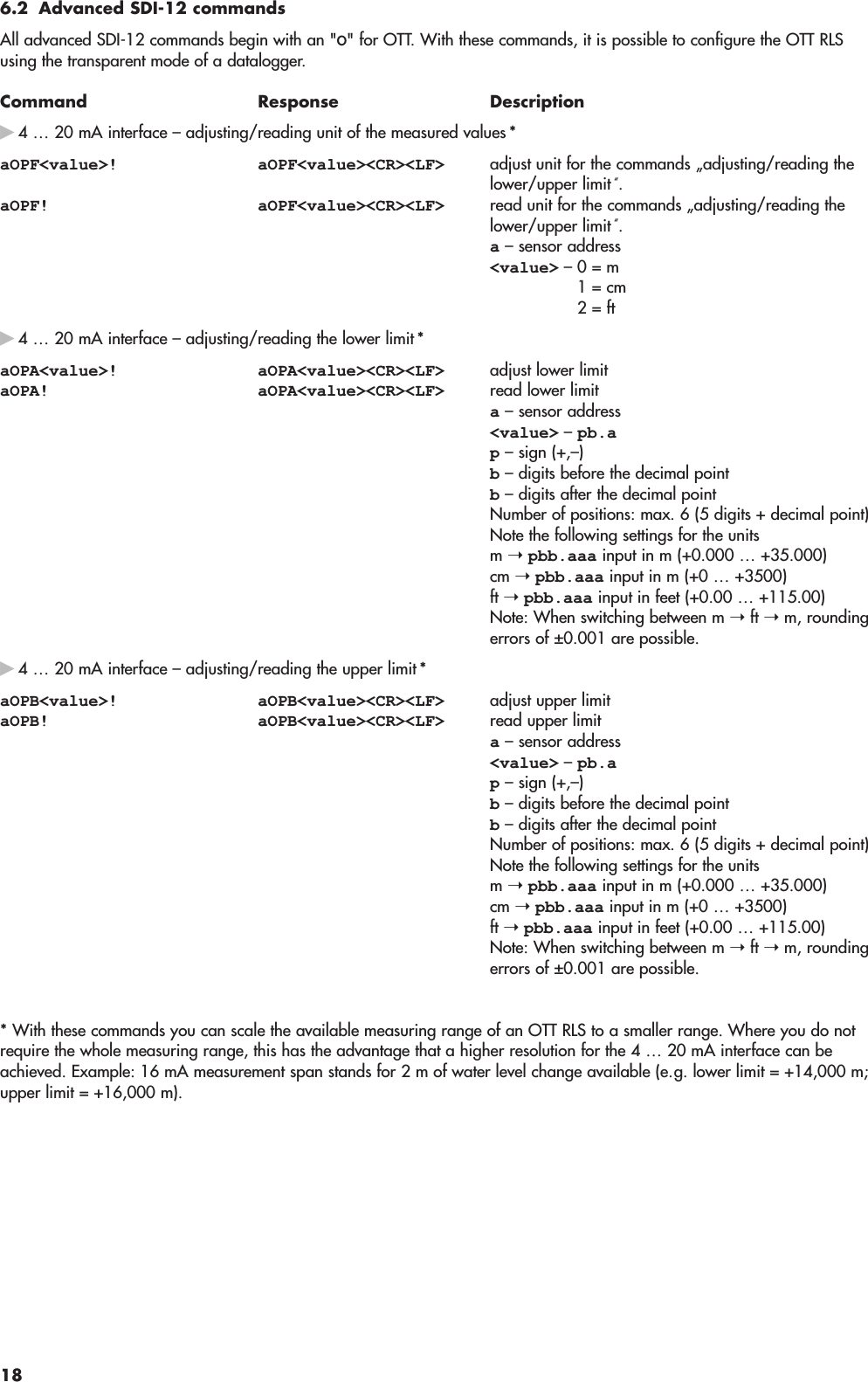
![6 SDI-12 commands and responses6.1 Standard commandsAll SDI-12 standard commands are implemented in the OTT RLS: The following SDI-12 standard commands are relevant forthe operation of the OTT RLS:Command Response Descriptiona! a<CR><LF> confirmation active a- sensor addressaI! allccccccccmmmmmm… send identification…vvvxxxx<CR><LF> a – Sensor addressll – SDI-12 protocol version cccccccc – manufacturer's identification (companyname)mmmmmm – sensor identification vvv – sensor version xxxxxx – serial numberOTT RLS reply= 13OTT HACH...RLS100xxxxxxaAb! b<CR><LF> change address a– old sensor address b– new sensor address?! a<CR><LF> query address a– sensor addressaM! atttn<CR><LF> start measurementa– sensor addressttt – Time in seconds until the sensor has deter-mined the measurement result OTT RLS reply = 20 secondsn– number of measured values OTT RLS reply = 7aD0! … aD6! a<value><CR><LF> send data a– sensor address D0: level [m] <value> – pbb.aaaD1: level [cm] <value> – pbbbbD2: level [ft] <value> – pbbb.aaD3: status <value> – b 0 = measured value OK 1 = no target recognized 2 = internal error 3 = variance of individual measurements too large<value> = p– sign (+,–) b– digit (before the decimal point) a– digit after the decimal pointMore information on the SDI-12 standard commands can be found in the document SDI-12; A Serial-Digital Interface Standardfor Microprocessor-Based Sensors; Version 1.3(see Internet pagewww.sdi-12.org).17](https://usermanual.wiki/Ott-Hydromet/OTTRLS/User-Guide-835139-Page-17.png)