Ott Hydromet OTTRLS Radar Level Sensor User Manual Anleitung RLS Zul EN
Ott Hydromet GmbH Radar Level Sensor Anleitung RLS Zul EN
User Manual
English
Operating instructions
Radar Level Sensor
OTT RLS
We reserve the right to make technical changes and improvements without notice.

3
Table of contents
1 Scope of supply . . . . . . . . . . . . . . . . . . . . . . . . . . . . . . . . . . . . . . . . . . . . . . . . . . . . . . . . . . . . . . . . . . . . . . 4
2 Order numbers . . . . . . . . . . . . . . . . . . . . . . . . . . . . . . . . . . . . . . . . . . . . . . . . . . . . . . . . . . . . . . . . . . . . . . . 4
3 Basic safety information . . . . . . . . . . . . . . . . . . . . . . . . . . . . . . . . . . . . . . . . . . . . . . . . . . . . . . . . . . . . 5
4 Introduction . . . . . . . . . . . . . . . . . . . . . . . . . . . . . . . . . . . . . . . . . . . . . . . . . . . . . . . . . . . . . . . . . . . . . . . . . . 6
5 Installing the OTT RLS . . . . . . . . . . . . . . . . . . . . . . . . . . . . . . . . . . . . . . . . . . . . . . . . . . . . . . . . . . . . . . . 8
5.1 Criteria for selecting a suitable mounting location . . . . . . . . . . . . . . . . . . . . . . . . . . . . . . . . . . . . . . 8
5.2 Notes on power supply . . . . . . . . . . . . . . . . . . . . . . . . . . . . . . . . . . . . . . . . . . . . . . . . . . . . . . . . . . . . . . 9
5.3 Suitable cable types when using the RS-485 interface . . . . . . . . . . . . . . . . . . . . . . . . . . . . . . . . . . 9
5.4 Mounting the OTT RLS . . . . . . . . . . . . . . . . . . . . . . . . . . . . . . . . . . . . . . . . . . . . . . . . . . . . . . . . . . . . . . . 9
5.5 Connecting the OTT RLS to any datalogger using an SDI-12 interface . . . . . . . . . . . . . . . . . . . 11
5.6 Connecting the OTT RLS to any datalogger using a 4 … 20 mA interface . . . . . . . . . . . . . . . . 11
5.7 Note on using the OTT RLS RS-485 interface in combination with any datalogger . . . . . . . . 11
5.8 Connecting the OTT RLS to LogoSens 2 or DuoSens using an SDI-12 or RS-485 interface . 12
5.9 Connecting the OTT RLS to LogoSens 2 or DuoSens using a 4 … 20 mA interface . . . . . . . . 14
6 SDI-12 commands and responses . . . . . . . . . . . . . . . . . . . . . . . . . . . . . . . . . . . . . . . . . . . . . . . . . 17
6.1 Standard commands . . . . . . . . . . . . . . . . . . . . . . . . . . . . . . . . . . . . . . . . . . . . . . . . . . . . . . . . . . . . . . . . . 18
6.2 Advanced SDI-12 commands . . . . . . . . . . . . . . . . . . . . . . . . . . . . . . . . . . . . . . . . . . . . . . . . . . . . . . . . . 19
7 Carrying out maintenance work . . . . . . . . . . . . . . . . . . . . . . . . . . . . . . . . . . . . . . . . . . . . . . . . . . . 19
8 Repair . . . . . . . . . . . . . . . . . . . . . . . . . . . . . . . . . . . . . . . . . . . . . . . . . . . . . . . . . . . . . . . . . . . . . . . . . . . . . . . . . 19
9 Searching for disruptions/error correction . . . . . . . . . . . . . . . . . . . . . . . . . . . . . . . . . . . . . . . . 20
10 Note about the disposal of old units . . . . . . . . . . . . . . . . . . . . . . . . . . . . . . . . . . . . . . . . . . . . . . 21
11 Determining the maximum load resistance at the 4 … 20 mA interface . . . . . . . 22
12 Technical Data . . . . . . . . . . . . . . . . . . . . . . . . . . . . . . . . . . . . . . . . . . . . . . . . . . . . . . . . . . . . . . . . . . . . . . . . 23

1 Scope of supply
ᮣOTT RLS – 1 Radar sensor OTT RLS, two part gimbal-mounting (consisting of device and
wall brackets)
– 1 Set of installation fittings (4 x wood screws 6 x 40; 4 x plastic plugs S8)
– 2 Double open-ended wrenches size 10 x 13
– 1 Operating instructions
– 1 Factory acceptance test certificate (FAT)
2 Order numbers
ᮣOTT RLS Radar sensor OTT RLS 63.105.001.9.2
– Version 1: 4 … 20 mA + RS-485 interface
– Version 2: 4 … 20 mA + SDI-12 interface
4

3 Basic safety information
ᮣRead these operating instructions before using the OTT RLS for the first time!
Make yourself completely familiar with the installation and operation of the
OTT RLS! Retain these operating instructions for later reference.
ᮣThe OTT RLS is used for contactless level measurement of surface waters. Only
use the OTT RLS in the manner described in these operating instructions! For
further information ➝ see Chapter 4, "Introduction".
ᮣNote all the detailed safety information given within the individual work steps.
All safety information in these operating instructions are identified with the
warning symbol shown here.
ᮣNever use the OTT RLS in areas where there is a danger of explosion. For fur-
ther information ➝ see Chapter 5, "Installing the OTT RLS".
ᮣNote that the OTT RLS may only be installed by a professional (e.g. qualified
electrician). For further information ➝ see Chapter 5, "Installing the OTT RLS".
ᮣProtect the power supply connection with a fuse (5 ampere, blowing speed:
fast). For further information ➝ see Chapter 5, "Installing the OTT RLS".
ᮣIt is essential to comply with the electrical, mechanical and climatic specifi-
cations given in the Technical Data section. For further information ➝ see
Chapter 12, "Technical data".
ᮣDo not make any changes or retrofits to the OTT RLS. If changes or retrofits are
made, all guarantee claims are voided. Furthermore, the radio approval required
for its operation is void!
ᮣHave a faulty OTT RLS inspected and repaired by our repair center. Never
make any repairs yourself under any circumstances. For further information
➝ see Chapter 8, "Repair".
ᮣDispose of the OTT RLS properly after taking out of service. Never put the
OTT RLS into the normal household waste. For further information ➝ see
Chapter 10, "Note about the disposal of old units".
FCC
Note: This equipment has been tested and found to comply with the limits for a
Class A digital device, pursuant to part 15 of the FCC Rules. These limits are
designed to provide reasonable protection against harmful interference when the
equipment is operated in a commercial environment. This equipment generates,
uses, and can radiate radio frequency energy and, if not installed and used in
accordance with the instruction manual, may cause harmful interference to radio
communications. Operation of this equipment in a residential area is likely to
cause harmful interference in which case the user will berequired to correct the
interference at his own expense.
Industry Canada
This Class A digital apparatus complies with Canadian ICES-003.
Cet appareil numérique de la classe A est conforme à la norme NMB-003 du
Canada.
5
4 Introduction
The OTT RLS radar sensor is used for contactless measurement of the levels of sur-
face water.
The OTT RLS is based on impulse radar technology. The transmitting antenna
transmits short radar pulses in the 24 GHz ISM band. The separate receiver
antenna receives the pulses reflected from the water and uses them to determine
the distance between sensor and water surface: the time taken by the radar pulses
from transmission to reception is proportional to the distance between sensor and
water surface. The actual water level of the waterway is then calculated using a
scaling function by a datalogger attached to the radar sensor. For this a reference
level has to be input when starting.
The transmission antenna has a beam width of approx. ± 6°. The resulting sensor
beam can be seen in the depiction in Figures 2 and 3.
Three standardised electrical interfaces are available for connecting the OTT RLS
to a datalogger or peripheral devices: 4 … 20 mA, SDI-12 and RS-485 (SDI-12
protocol).
A gimbal mounting allows problem-free and simple mounting even on slanted
surfaces. A waterproof terminal area can be found under a removable screw
cover for attaching the sensor cable.
Due to the low power consumption, a cable length of up to 1000 meters can be
implemented for the power supply.
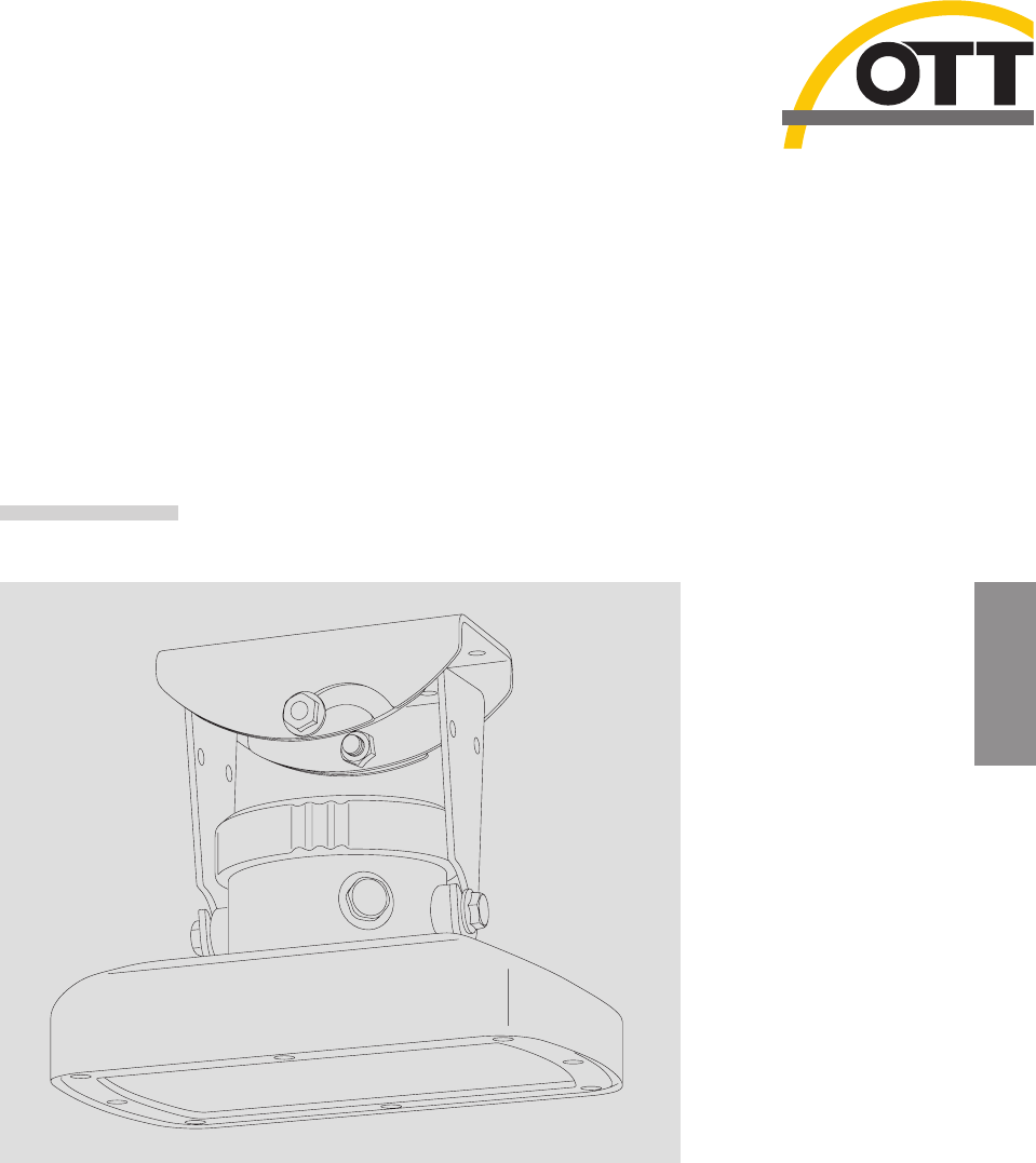
The complete radar sensor is constructed to be proof against flooding (diving bell
principle).
Removable
screw cover
Cover for transmission and
receiving antenna (radom)
Gimbal
mounting
Fig. 1: Overview of radar sensor OTT RLS.
6
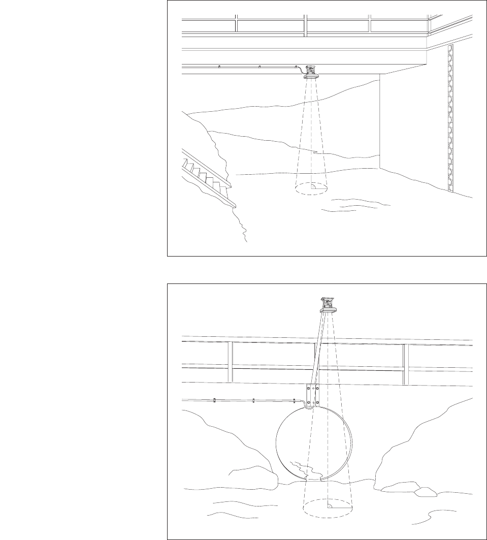
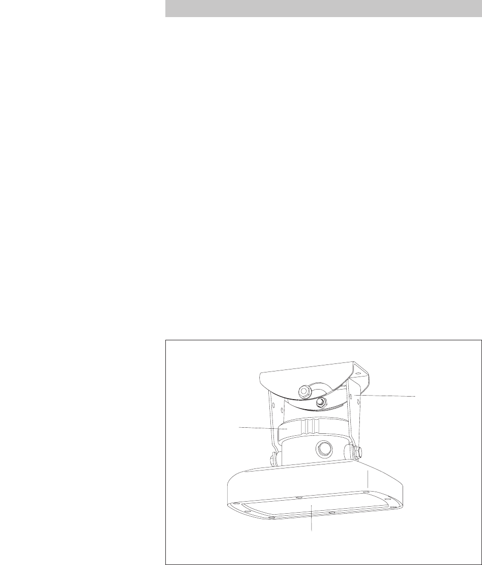
OTT RLS
Sensor beam
Fig. 3: Application example 2:
Mounting the OTT RLS on an auxiliary
construction, e.g. metal stand with
mounting plate.
OTT RLS
Sensor beam
Fig. 2: Application example 1:
Mounting the OTT RLS on a bridge.
The projection of the sensor beam onto the
water surface is virtually round.
7

5 Installing the OTT RLS
Caution: The installation of the OTT RLS may only be undertaken by qualified
persons (e.g. electrician)!
The OTT RLS has no Ex protection!
5.1 Criteria for selecting a suitable mounting location
ᮣLocations that come into question include, for example, bridges and auxiliary
constructions directly above the waterway section to be measured.
ᮣThe minimum distance between lower edge of the sensor and water surface
must be 0.8 m (dead area in which no useable measurement is possible).
ᮣSelect a mounting point high enough so that measurement is possible even with
high water levels.
ᮣThe mounting point must be steady. Vibrations and movement of the mounting
point must be avoided. Bridges are affected by movements of several centime-
ters as a result of load changes and temperature movements.
ᮣThe water surface must be as smooth as possible in the area of the sensor
beam. Avoid turbulent areas and areas where obstructions in the waterway or
bridge piers cause changes in the water level.
ᮣThe area within the sensor beam (see Figures 2 and 3) must be completely free
of obstructions. Table for approximating the size of the sensor beam:
Distance Diameter
OTT RLS – Sensor beam
Water surface
5 m 1.06 m
10 m 2.12 m
15 m 3.19 m
20 m 4.25 m
25 m 5.31 m
30 m 6.38 m
35 m 7.44 m
The diameters given are minimum sizes. Where possible, select an area free of
obstruction that is clearly larger.
ᮣAvoid large metal surfaces near the sensor beam (reflections from these surfaces
can distort the measurement result).
ᮣThe climate specifications in the technical data must be kept to at the mounting
location.
ᮣStilling wells are unsuitable as a mounting location.
WARNING Danger of explosion due to spark formation and electrostatic
discharge
The use of the OTT RLS in explosive atmospheres can lead to the danger of ignition
of this atmosphere. An explosion resulting from this involves the risk of very severe
material and personal damage.
ᮣNever operate the OTT RLS in explosive areas (e.g. in sewers).
8
5.2 Notes on power supply
The OTT RLS requires a power supply of 9.6 … 28 V direct current of type
12/24 V DC (e.g. a battery or mains connection with galvanically isolated low
safety voltage).
The OTT RLS is immediately ready for operation after connecting the power supply.
Warning:
ᮣThe power supply must be protected by a fuse (5 ampere, blowing speed: fast)
on the input side.
ᮣWhen using solar panels, we recommend the use of an overvoltage protection
device.
5.3 Suitable cable types when using the RS-485 interface
The maximum length of the cable is 1,000 m. Recommended cable type: Twisted-
pair cable; unshielded (alternatively: shielded). The wires intended for the power
supply can be twisted pair, but do not have to be.
ᮣup to 400 m cable length: 2 x 2 x 0.34 mm2
e.g. Lapp UNITRONIC FD CP (TP) plus UL/CSA*, item no. 0030928;
external diameter 8.8 mm
ᮣ400 … 600 m cable length: 2 x 2 x 0.5 mm2
e.g. Lapp UNITRONIC FD CP (TP) plus UL/CSA*, item no. 0030937;
external diameter 9.3 mm
ᮣ600 to 1,000 m cable length: 2 x 2 x 0.75 mm2
e.g. Lapp UNITRONIC FD CP (TP) plus UL/CSA*, item no. 0030946;
external diameter 10.2 mm
* The outer casing of these cables is UV-steady and therefore ideally suitable for the external area. It is
not necessary to attach the screen at these cable examples.
5.4 Mounting the OTT RLS
Assembling the gimbal mounting
Mounting surface: concrete or masonry
ⅥMake four holes (Ø 8 mm/43 mm) deep using a hammer drill (use wall brack-
et as a template).
ⅥInsert the four plastic plugs supplied into the holes.
ⅥAttach the wall bracket using the four wood screws supplied.
ⅥInsert housing bracket (without sensor) into wall bracket and lightly tighten the
hex bolts A.
Mounting surface: auxiliary construction, e. g. metal stand with mounting plate
ⅥDrill four holes (Ø 7 mm) in the mounting plate (use wall bracket as a template).
ⅥAttach the wall bracket e. g. using four hex bolts (M6) and nuts.
ⅥInsert housing bracket (without sensor) into wall bracket and lightly tighten the
hex bolts A.
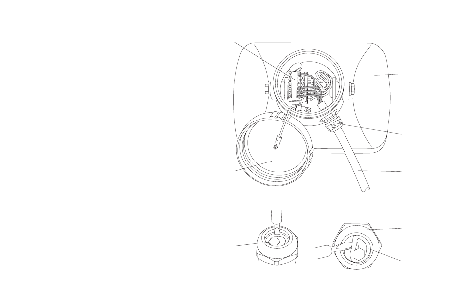
Preparing the cable gland
ⅥRemove "Globemarker" (hexagon with size indication of cable diameters that
can be used).
ⅥWith a cable diameter of 7.0 … 11.0 mm, remove inlet: insert screwdriver
vertically into the seam. See Figure 4. Minimum cable diameter with inlet:
4.0 mm.
ⅥLever out inlet with screwdriver.
ⅥInsert cable.
9
Mounting the sensor
ⅥUnscrew screw cover.
ⅥInsert connecting cable through cable gland.
ⅥRemove insulation from connecting cable.
ⅥWith flexible wires: put end caps on the wires.
ⅥConnect the connecting cable to the terminal block. Take note for this of Chapter
5.5 to 5.9! If required, the terminal strip can be pulled out for connecting.
ⅥRetighten connecting cable as necessary.
ⅥTighten the tightening nut of the cable gland (torque for tightening nut: 6 Nm).
ⅥScrew on the screw cover and tighten firmly by hand.
ⅥInsert sensor into housing bracket and lightly tighten the hex bolts B.
ⅥAlign the housing parallel (longitudinal and lateral axis) with the water surface
using a spirit level.
ⅥTighten the hex bolts B on the housing shell.
ⅥTighten the hex bolts A on the wall and housing brackets.
ⅥCheck alignment of the OTT RLS once more.
Warning:
ᮣThe alignment of the sensor parallel to the water surface must be carried out as
accurately as possible!
➝If alignment is out by 1.0 °, this leads to a linearity error of approx.
0.15 mm per meter change in the distance.
➝If alignment is out by 2.5 °, this leads to a linearity error of approx. 1 mm
per meter change in the distance.
➝If alignment is out by 5 °, this leads to a linearity error of approx. 4 mm per
meter change in the distance.
ᮣEnsure no moisture enters the connection area when the screw cover is open!
Removable
screw cover
Cable gland
Screw
terminal strip
Sensor
Cable gland
Inlet
Connecting
cable
Globemarker
Fig. 4: OTT RLS – connection area.
10
5.5 Connecting the OTT RLS to any datalogger using an SDI-12
interface
ⅥConnect the OTT RLS to an SDI-12 input of the datalogger. Follow the datalog-
ger handbook as you do this. Refer to Figure 6 for the connection assignments
of the OTT RLS.
5.6 Connecting the OTT RLS to any datalogger using a 4 … 20 mA
interface
ⅥConnect the OTT CBS to a 4 … 20 mA input of the datalogger. Follow the dat-
alogger handbook as you do this as well as Chapter 12 of these instructions.
Refer to Figure 7 for the connection assignments of the OTT RLS. Contacts used:
1, 4, 5 and 7.
5.7 Note on using the OTT RLS RS-485 interface in combination
with any datalogger
The RS-485 interface can only be used with an OTT datalogger. In this case, the
transmission protocol via the physical RS-485 interface is the SDI-12 protocol.
Connect OTT RLS via the RS-485 interface to the OTT LogoSens/DuoSens ➝ see
Chapter 5.8, Method B.
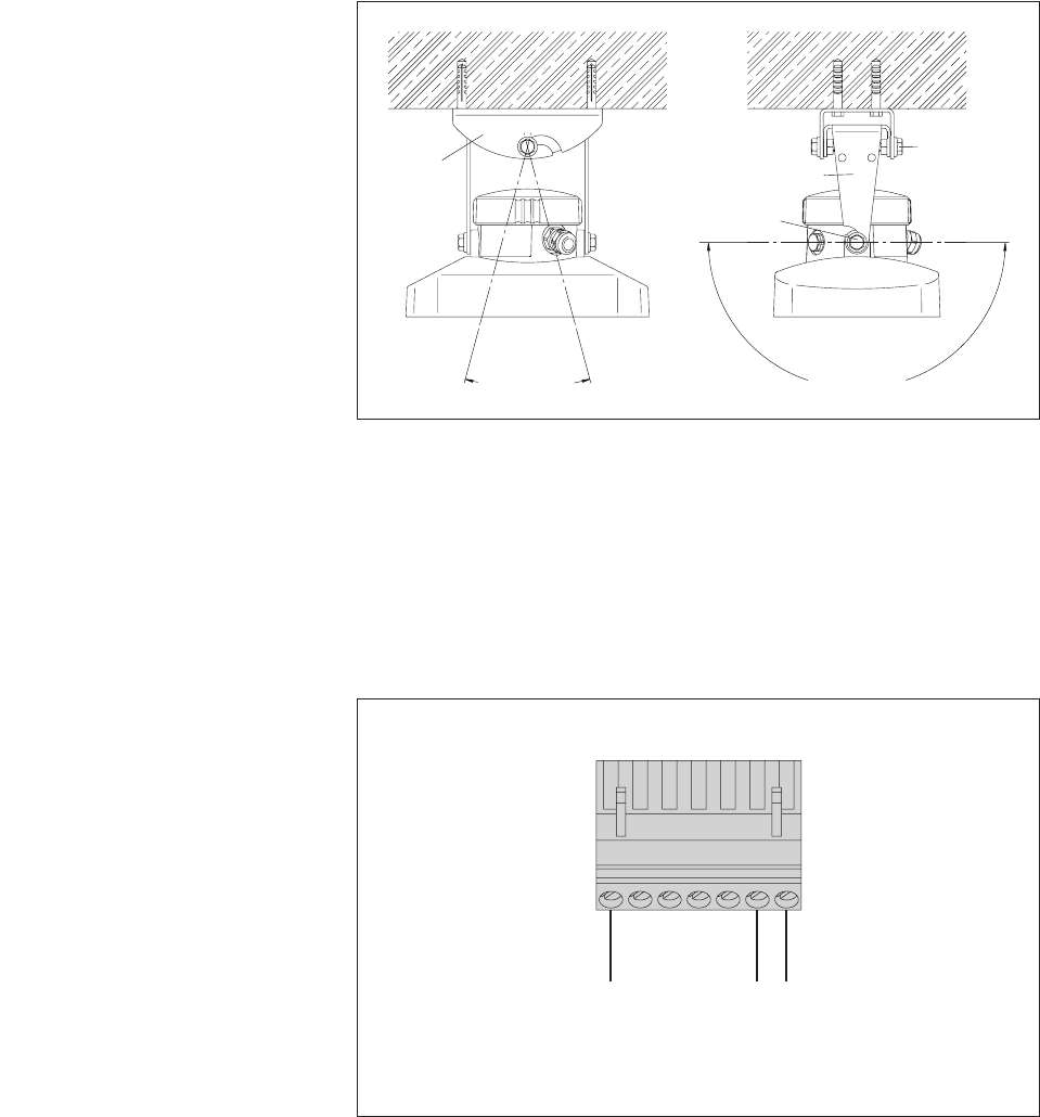
+12 V
GND
SDI-12 DATA
5423176
RLS
Abb. 6: Connecting the OTT RLS to any
datalogger using an SDI-12 interface.
max. ±90 °
Hex
bolt A
Hex bolt B
Wall
bracket Housing bracket
max. ±15 °
Fig. 5: OTT RLS – rotation range
of gimbal mounting.
11
5.8 Connecting the OTT RLS via SDI-12 or RS-485 interface to
LogoSens 2 or DuoSens
Method A: Connecting the OTT RLS via the SDI-12 interface (protocol and phys-
ical interface: SDI-12). The maximum length of the cable is 70 m. Recommended
cable cross-section: 0.25 mm2:
ⅥConnect the OTT RLS to the LogoSens 2 Station Manager or to the DuoSens
Compact Datalogger as shown in Figure 8. Take note of the operating instruc-
tions for the LogoSens 2/DuoSens.
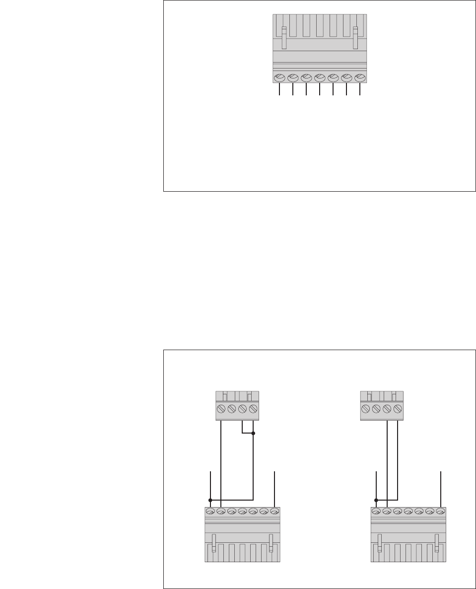
SDI-12
Input
A … R
4312
LogoSens 2
SDI-12
Input
A
4312
DuoSens
RLS
5423176
RLS
5423176
+9,6 … 28 V
GND
+9,6 … 28 V
GND
Fig. 8: Connecting the OTT RLS to LogoSens
2 or DuoSens using an SDI-12 interface.
The letters above the screw terminal strip
identify the possible connections on the
LogoSens 2/DuoSens.
4 … 20 mA +
4 … 20 mA –
GND
RS-485 B *
RS-485 A *
SDI-12 DATA
* SDI-12 protocol via physical RS-485 interface
(for connecting to OTT DuoSens and OTT LogoSens)
5423176
+9,6 … 28 V
Fig. 7: OTT RLS screw terminal strip.
Please note: The 4 … 20 mA interface
cannot be used parallel to the SDI-12
or RS-485 interfaces.
12
Method B: Connect OTT RLS using the physical RS-485 interface (SDI-12 proto-
col via physical RS-485 interface). Refer to Chapter 5.3 for the maximum cable
length and the recommended cross-section of the cable:
ⅥConnect the OTT RLS to the LogoSens 2 Station Manager or to the DuoSens
Compact Datalogger as shown in Figure 9. Take note of the operating instruct-
ions for the LogoSens 2/DuoSens.
Configuring the LogoSens 2/DuoSens for the OTT RLS with SDI-12
interface
ⅥCreate a LogoSens 2/DuoSens channel with
SDI-12 Master
or
OTT SDI RS485
function block (
serial sensors
tab).
ⅥApply the following settings:
ᮣTerminal block LogoSens 2: A … R
DuoSens
SDI-12 Master
: A 3-4 (specified)
DuoSens
OTT SDI RS485
: A 1-2 (specified)
terminal block used (screw terminal strip) of the
LogoSens 2/DuoSens.
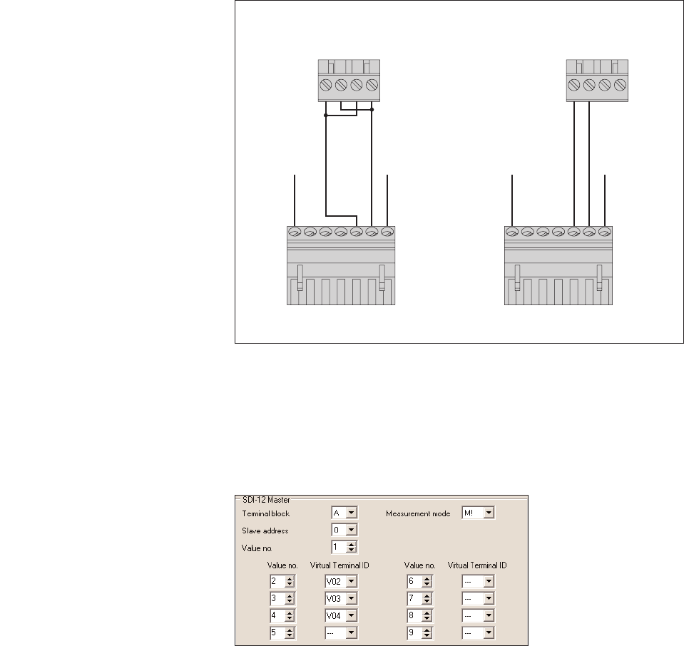
Fig. 10: Adjusting the operating parameters
of the LogoSens 2/DuoSens
SDI-12 Master
function block.
The function block
OTT SDI RS485
is set in the same way.
RS-485
Input
A … R
4312
LogoSens 2
RS-485
Input
A
RLS
4312
DuoSens
RLS
54231765423176
GND
+9,6 … 28 V
GND
+9,6 … 28 V
Fig. 9: Connecting the OTT RLS to LogoSens
2 or DuoSens using an RS-485 interface
(SDI-12 protocol).
The letters above the screw terminal
strip identify the possible connections
on the LogoSens 2/DuoSens.
13
ᮣSlave address SDI-12 bus address. Each slave address may only
be allocated once to an SDI-12 bus line. (check-
ing/setting: see operating instructions LogoSens
2/DuoSens, Chapter
SDI-12 transparent mode
.)
Typical setting:
0
(only one OTT RLS is connected
to the terminal block; no bus operation).
ᮣValue no. identifies which value (the xth of
n
values) of the
OTT RLS is recorded in this channel. Typical set-
ting:
1
(first of three values: level in [m])
ᮣMeasurement mode
M!
(for the maximum 3 values + status information
of the OTT RLS).
ᮣAllocation of the other two measured values + status
information of the OTT RLS to virtual terminals
(level in [cm]; level in [ft]; status information; see
Chapter 6.1 for further information; command
aM!).
ⅥIn the relevant
Channel
function blocks, adjust the required units and number of
digits after the decimal place (m: 3; cm: 0; ft: 2).
Note: To record all three values + status information of an OTT RLS, four chan-
nels in the LogoSens 2/DuoSens are thus necessary. The first channel contains the
function block
SDI-12 Master
or
OTT SDI RS485
as the input signal. The other
channels each contain a function block
Virtual Sensor
(V02 to V04) as the input
signal. Naturally, just individual channels can be recorded. In this case, there are
fewer entries required in the
Value no./Virtual terminal ID
field.
Please note: The measuring time is approx. 20 seconds.
5.9 Connecting the OTT RLS to LogoSens 2 or DuoSens using a
4 … 20 mA interface
ⅥConnect the OTT RLS to the LogoSens 2 Station Manager or to the DuoSens
Compact Datalogger as shown in Figure 11 and 12. Take note of the operating
instructions for the LogoSens 2/DuoSens. Maximum cable length/recommended
cable cross-section: Ensure that the ohm cable resistance together with any resis-
tor present does not exceed the maximum permitted load resistance (see
Chapter 11)!
Value no./
Virtual terminal ID
14
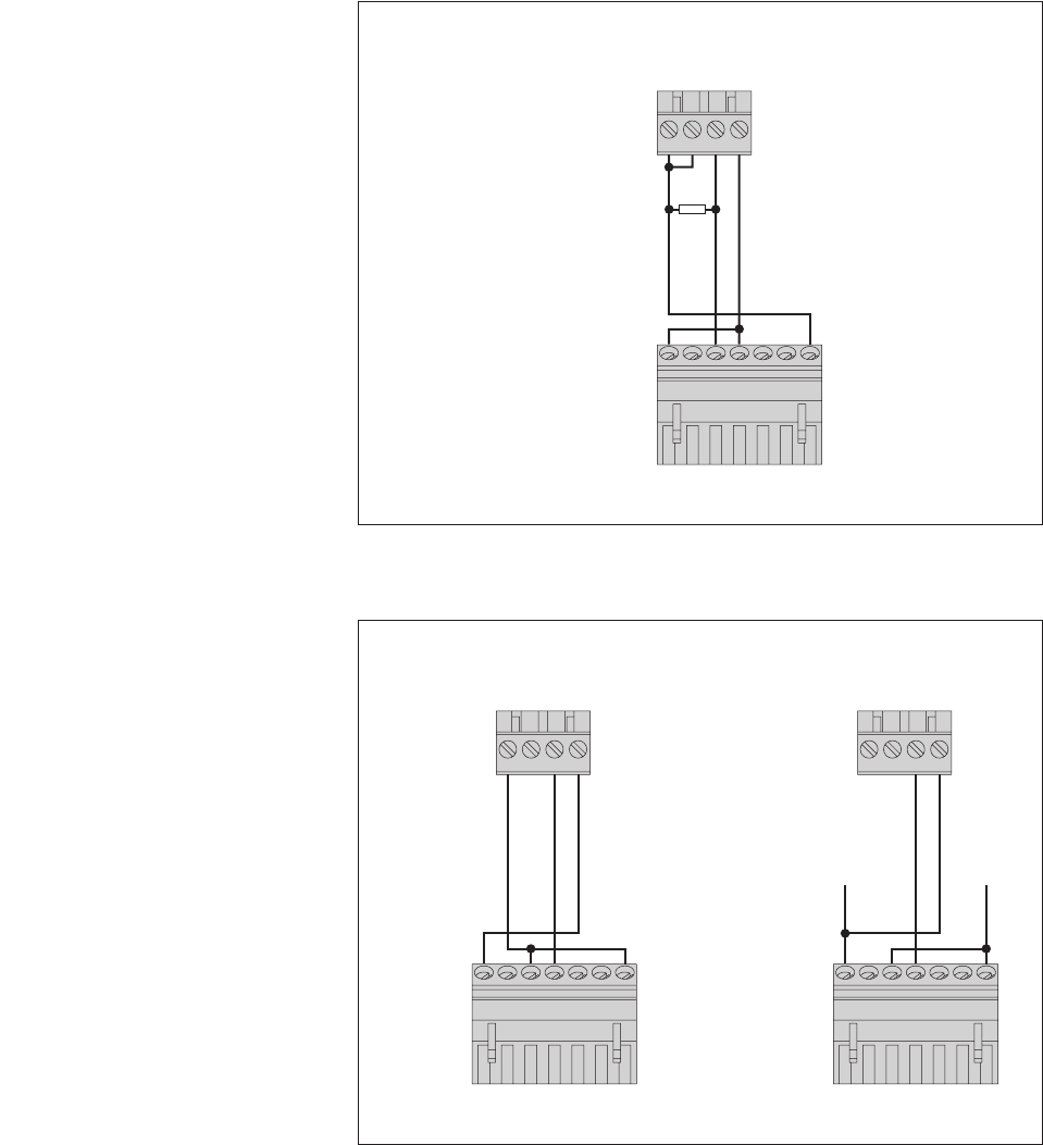
4 … 20 mA
Input
C … F*
4312
5423176
DuoSens
RLS
* only with a DuoSens
with analog extension
4 … 20 mA
Input
C … F*
4312
5423176
DuoSens
RLS
GND
+9,6 … 28 V
Fig. 12: Connecting the OTT RLS to Duo-
Sens using a 4 … 20 mA interface.
The letters above the screw terminal
strip identify the possible connections
on the DuoSens.
The supply to the current loop in
the application case shown on the
left is via the OTT RLS.
4 … 20 mA Input
A … R
4312
LogoSens 2
RLS
5423176
100 Ohm resistor
Fig. 11: Connecting the OTT RLS to
LogoSens 2 using a 4 … 20 mA interface
Use the 100 Ohm OTT resistor
(order number: 55.550.126.4.2)!
The letters above the screw terminal
strip identify the possible connections
on the LogoSens 2.
The supply to the current loop in the applica-
tion case shown is via the OTT LogoSens 2.
15
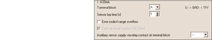
Configuring the LogoSens 2/DuoSens for OTT RLS with 4 … 20 mA
interface
ⅥCreate a LogoSens 2/DuoSens channel with function block
I 4-20 mA
(LogoSens 2) or
U/I/Pt100/…
(DuoSens) (
Analog sensors
tab).
ⅥApply the following settings:
ᮣTerminal block LogoSens 2: A … R DuoSens: C ... F ter-
minal block used (screw terminal strip) of
the LogoSens 2/DuoSens.
ᮣSet to
I 4-20 mA ext.
ᮣSensor lag time (s) switches on the LogoSens 2/DuoSens input
1 second before the actual measurement
process
ᮣif required: record error codes on range
overflow
ᮣnot required with an OTT RLS
ⅥInsert a
2-point scaling
function block into this channel and set the appropriate
water levels for the electrical values measured (e. g. Point 1: 4 ➝35; Point 2:
20 ➝0).
ⅥIn the
Channel
function block, set the unit and number of digits after the decimal
place (m: 3; cm: 0; ft: 2).
Note on points 5.5 to 5.9
ᮣTo reference OTT RLS measured values to a level zero: Input the contact
gauge/staff gauge measurement, for example using the scaling function of the
datalogger, connected to the OTT RLS (e.g. LogoSens 2/DuoSens).
Auxiliary sensor supply via
relay contact at terminal block
(only for LogoSens 2)
□Error code if range overflow
Measurement mode
(only with DuoSens)
Fig. 13: Setting operating parameters of the
LogoSens 2
I 4-20 mA
function block.
The DuoSens function block
U/I/Pt100/…
is set in the same way.
16

6 SDI-12 commands and responses
6.1 Standard commands
All SDI-12 standard commands are implemented in the OTT RLS: The following SDI-12 standard commands are relevant for
the operation of the OTT RLS:
Command Response Description
a! a<CR><LF> confirmation active a- sensor address
aI! allccccccccmmmmmm… send identification
…vvvxxxx<CR><LF> a – Sensor address
ll – SDI-12 protocol version
cccccccc – manufacturer's identification (company
name)
mmmmmm – sensor identification
vvv – sensor version
xxxxxx – serial number
OTT RLS reply= 13OTT HACH...RLS100xxxxxx
aAb! b<CR><LF> change address
a– old sensor address
b– new sensor address
?! a<CR><LF> query address
a– sensor address
aM! atttn<CR><LF> start measurement
a– sensor address
ttt – Time in seconds until the sensor has deter-
mined the measurement result
OTT RLS reply = 20 seconds
n– number of measured values
OTT RLS reply = 7
aD0! … aD6! a<value><CR><LF> send data
a– sensor address
D0: level [m]
<value> – pbb.aaa
D1: level [cm]
<value> – pbbbb
D2: level [ft]
<value> – pbbb.aa
D3: status
<value> – b
0 = measured value OK
1 = no target recognized
2 = internal error
3 = variance of individual measurements too large
<value> = p– sign (+,–)
b– digit (before the decimal point)
a– digit after the decimal point
More information on the SDI-12 standard commands can be found in the document
SDI-12; A Serial-Digital Interface Standard
for Microprocessor-Based Sensors; Version 1.3
(see Internet page
www.sdi-12.org
).
17
6.2 Advanced SDI-12 commands
All advanced SDI-12 commands begin with an "O" for OTT. With these commands, it is possible to configure the OTT RLS
using the transparent mode of a datalogger.
Command Response Description
ᮣ4 … 20 mA interface – adjusting/reading unit of the measured values *
aOPF<value>! aOPF<value><CR><LF> adjust unit for the commands „adjusting/reading the
lower/upper limit “.
aOPF! aOPF<value><CR><LF> read unit for the commands „adjusting/reading the
lower/upper limit “.
a– sensor address
<value> – 0 = m
1 = cm
2 = ft
ᮣ4 … 20 mA interface – adjusting/reading the lower limit *
aOPA<value>! aOPA<value><CR><LF> adjust lower limit
aOPA! aOPA<value><CR><LF> read lower limit
a– sensor address
<value> – pb.a
p– sign (+,–)
b– digits before the decimal point
b– digits after the decimal point
Number of positions: max. 6 (5 digits + decimal point)
Note the following settings for the units
m ➝pbb.aaa input in m (+0.000 … +35.000)
cm ➝pbb.aaa input in m (+0 … +3500)
ft ➝pbb.aaa input in feet (+0.00 … +115.00)
Note: When switching between m ➝ft ➝m, rounding
errors of ±0.001 are possible.
ᮣ4 … 20 mA interface – adjusting/reading the upper limit *
aOPB<value>! aOPB<value><CR><LF> adjust upper limit
aOPB! aOPB<value><CR><LF> read upper limit
a– sensor address
<value> – pb.a
p– sign (+,–)
b– digits before the decimal point
b– digits after the decimal point
Number of positions: max. 6 (5 digits + decimal point)
Note the following settings for the units
m ➝pbb.aaa input in m (+0.000 … +35.000)
cm ➝pbb.aaa input in m (+0 … +3500)
ft ➝pbb.aaa input in feet (+0.00 … +115.00)
Note: When switching between m ➝ft ➝m, rounding
errors of ±0.001 are possible.
* With these commands you can scale the available measuring range of an OTT RLS to a smaller range. Where you do not
require the whole measuring range, this has the advantage that a higher resolution for the 4 … 20 mA interface can be
achieved. Example: 16 mA measurement span stands for 2 m of water level change available (e.g. lower limit = +14,000 m;
upper limit = +16,000 m).
18

7 Carrying out maintenance work
The OTT RLS radar sensor is almost maintenance free. No setting or calibration
work is necessary. There are likewise no parts that need replacing regularly.
Carry out the following maintenance work at regular frequencies based on the
local circumstances:
ⅥCheck the OTT RLS for dirt (e.g. thick, dewy spider's webs or insect nests can
lead to impairment of the measured results). In this case, carefully clean the
sensor. At the same time, ensure that the setting of the gimbal mounting does
not change.
ⅥCheck for obstructions in the measurement beam (for example, for flotsam or
branches of trees and bushes growing into this area). In this case, remove all
obstructions.
ⅥCheck the plausibility of the measured values by comparing with a second sensor
or with a staff gauge.
Warning: Never open the housing of the OTT RLS (exception: connection area)!
There are no adjustment or operating elements inside the housing.
8 Repair
Ⅵ With a device defect, use Chapter 9 ,
Searching for disruptions/error correction
to see if you can resolve the problem yourself.
Ⅵ In case of device defects, please contact the repair center of OTT:
OTT MESSTECHNIK GmbH & Co. KG
Repaircenter
Ludwigstraße 16
87437 Kempten · Germany.
Telephone +49 (0)831/5617-433
Fax +49 (0)831/5617-439
repair@ott.com
Warning: Only have a defective OTT RLS checked and repaired by the OTT
repair center. Never make any repairs yourself under any circum-
stances. Any repairs or attempted repairs carried out by the cus-
tomer will result in the loss of any guarantee rights.
19

9 Searching for disruptions/error correction
Sensor does not respond to the SDI 12 interface
ᮣFuse in the power supply input side defective?
➝Replace fuse.
ᮣSensor correctly connected to a datalogger with SDI-12 input (master)?
➝Correct connection assignment.
ᮣPolarity of the power supply reversed?
➝Correct connection assignment.
ᮣPower supply < 9.6 V or > 28 V?
➝Correct level of voltage supplied (check the length and cross-section of the
connection cable).
ᮣIs the power supply direct current?
➝Only operate sensor with direct current.
4 .. 20 mA signal not present
ᮣSensor correctly connected to a datalogger or peripheral device to 4 .. 20 mA
input (check polarity)?
➝Correct connection assignment.
ᮣ4 .. 20 mA current loop correctly supplied through datalogger or OTT RLS
(internal/external supply)?
➝Correct connection assignment.
Measured value varies or is not present
ᮣSensor (front plate) dirty?
➝Carefully clean the sensor.
ᮣObstruction in the measurement beam?
➝Remove obstructions.
ᮣSensor aligned at right angles to the water surface?
➝Correct sensor alignment.
ᮣMounting location of the sensor steady (e.g. bridge movement)?
➝Optimize mounting location.
ᮣLarge metal surfaces near the sensor beam (e.g. piling)?
➝Optimize mounting location.
20

10 Note about the disposal of old units
Within the member countries of the European Union
In accordance with the European Union guideline 2002/96/EC, OTT takes back
old devices within the member countries of the European Union and disposes of
them in an appropriate way. The devices concerned by this are marked with the
symbol shown aside.
ⅥFor further information on the return procedure, please contact your ocal sales
contact. You will find the addresses of all sales partners in the internet on
"www.ott.com". Please take into consideration also the national implementation
of the EU guideline 2002/96/EC of your country.
For all other countries
ⅥDispose of the OTT RLS properly after taking out of service.
ⅥObserve the regulations valid in your country for the disposal of electronic
devices.
ⅥNever put the OTT RLS into the normal household waste.
21
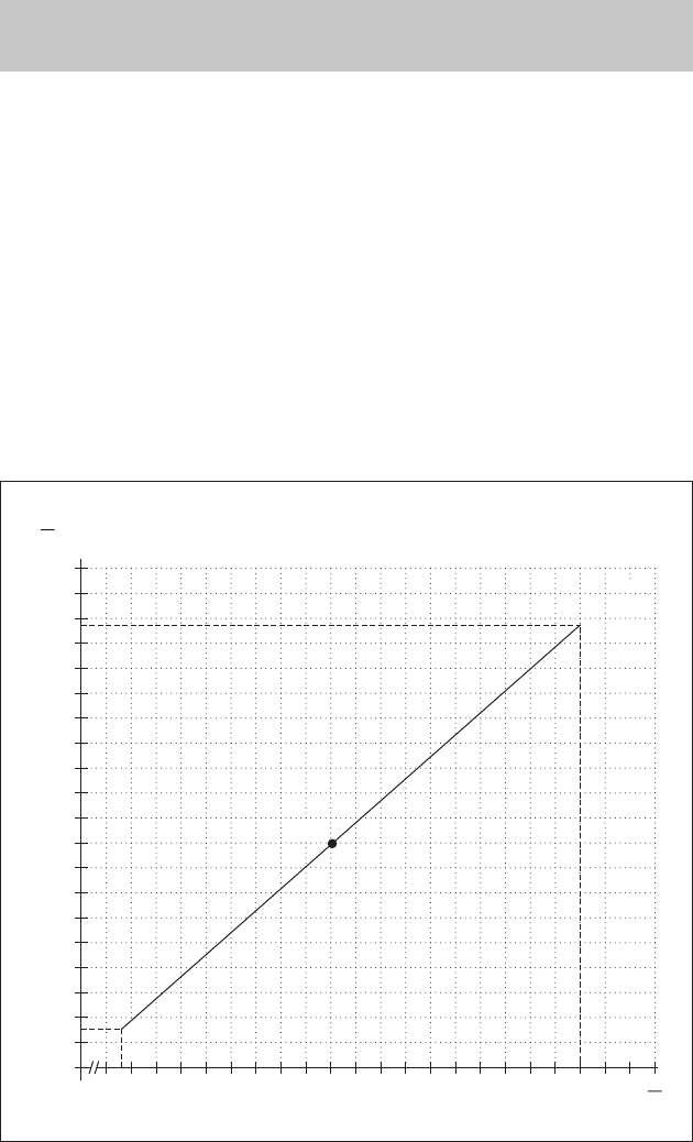
11 Determining the maximum load resistance
at the 4 … 20 mA interface
The load resistance (resistor) connected to the OTT RLS must not exceed a specific
maximum value. This value depends on the level of the supply voltage of the OTT
RLS. If the load resistance is greater, the output current can no longer be evaluat-
ed. Smaller load resistances are allowed.
ⅥRead off the maximum load resistance for your power supply from the follow-
ing diagram.
Example: Power supply 18 volt ➝max. load resistance 450 ohm.
The OTT RLS delivers an output current corresponding to the measured value
for a load resistance of up to 450 ohm.
ⅥDimension the connected electrical circuit accordingly. Check the input resis-
tance of the connected peripheral device for this purpose.
10 15 20 25 30 U
V
100
0
200
300
400
500
600
700
800
R
Ω
900
1000
Example
Figure 14. Diagram to determine the
maximum load resistance as a function
of the power supply.
Minimum power supply: 9.6 V
Maximum power supply: 28 V
Resistor tolerance: 0.1 %/15 ppm.
22

12 Technical Data
Measuring range 0.8 … 35 m 80 … 3500 cm 2.6 … 115 ft
Resolution SDI-12 interface 0.001 m 1 cm 0.01 ft
Measuring time 20 seconds
Power supply 9.6 … 28 V DC, typ. 12/24 V DC
Power consumption
Measurement operation < 140 mW
Rest mode < 1 mW
Interfaces 4 … 20 mA, SDI-12, RS-485, two-wire (SDI-12 protocol)
Beam angle of antenna ±6 °
Materials
Housing ABA (UV-stabilized ABS)
Radom (front plate) TFM PTFE
Mounting 1.4301 (V2A)
Weight (including mounting) approx. 2.1 kg
Cable gland sealing range
with inlet (min. Ø … max. Ø) 4.0 … 7.0 mm
without inlet (min. Ø … max. Ø) 7.0 … 11.0 mm
Connection capacity of screw terminal strip
Solid conductor 0.25 … 2.5 mm2(AWG 24 to 12)
Wire with end cap and plastic collar 0.25 … 1.5 mm2
Terminal assignment screw terminal strip
Terminal 1 power supply
Terminal 2 RS-485 B
Terminal 3 RS-485 A
Terminal 4 4 … 20 mA –
Terminal 5 4 … 20 mA +
Terminal 6 SDI-12 DATA
Terminal 7 GND
Rotation range of gimbal mounting
Lateral axis ±90 °
Longitudinal axis ±15 °
Type of protection at horizontal installation IP 67 (submersion depth max. 1 m;
Submersion duration max. 48 h)
Dimensions L x W x H 222 mm x 152 mm x 190 mm
Temperature range
Operation –40 … +60 °C
Storage –40 … +85 °C
Relative humidity 0 … 100 % non-condensing
EMC limits and radio approvals
EMV for Short Range Device ETSI EN 301 489-3
Safety of equipment of low voltage device EN 60950-1
Approval for Short Range Device; Europe ETSI EN 300 440
Approval for Short Range Device; USA FCC 47 CFR Part 15
Approval for Short Range Device; Canada RSS 210 Issue 7
23
OTT MESSTECHNIK GmbH & Co. KG
Ludwigstrasse 16
87437 Kempten · Germany
Phone +49 (0)8 31 5617- 0
Fax +49 (0)8 31 56 17- 209
info@ott.com
www.ott.com
Document number
63.105.001.B.E 04-0807