Ott Hydromet RLS252 Radar Level Sensor User Manual
Ott Hydromet GmbH Radar Level Sensor
UserManual.wiki
>
Ott Hydromet
>
RLS252 User Manual
user manual
Navigation menu
Upload a User Manual
Namespaces
Wiki Guide
HTML
PDF
Info
Views
User Manual
Discussion / Help
Navigation
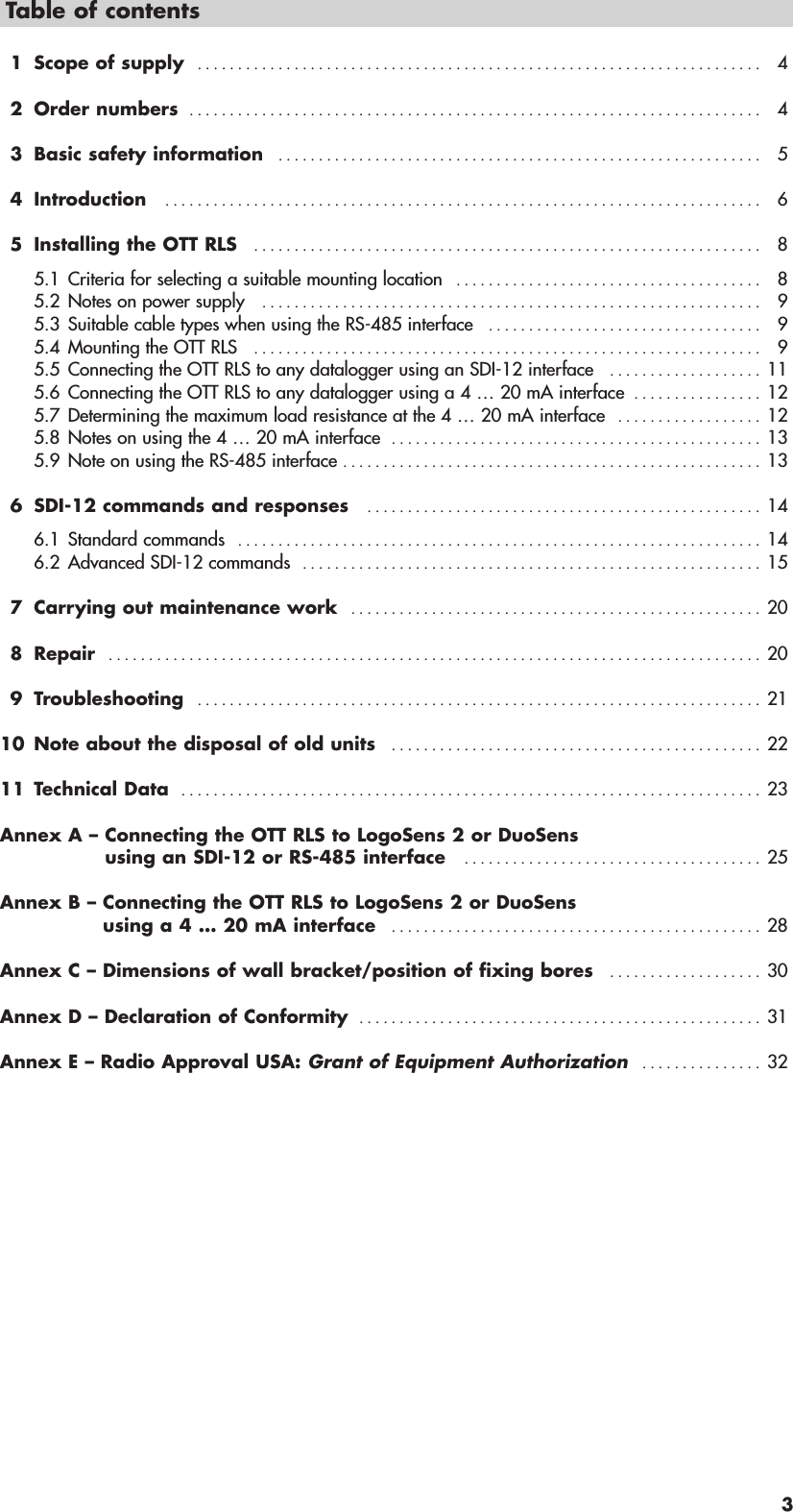
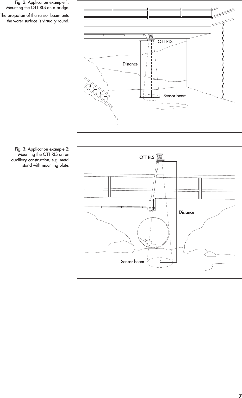
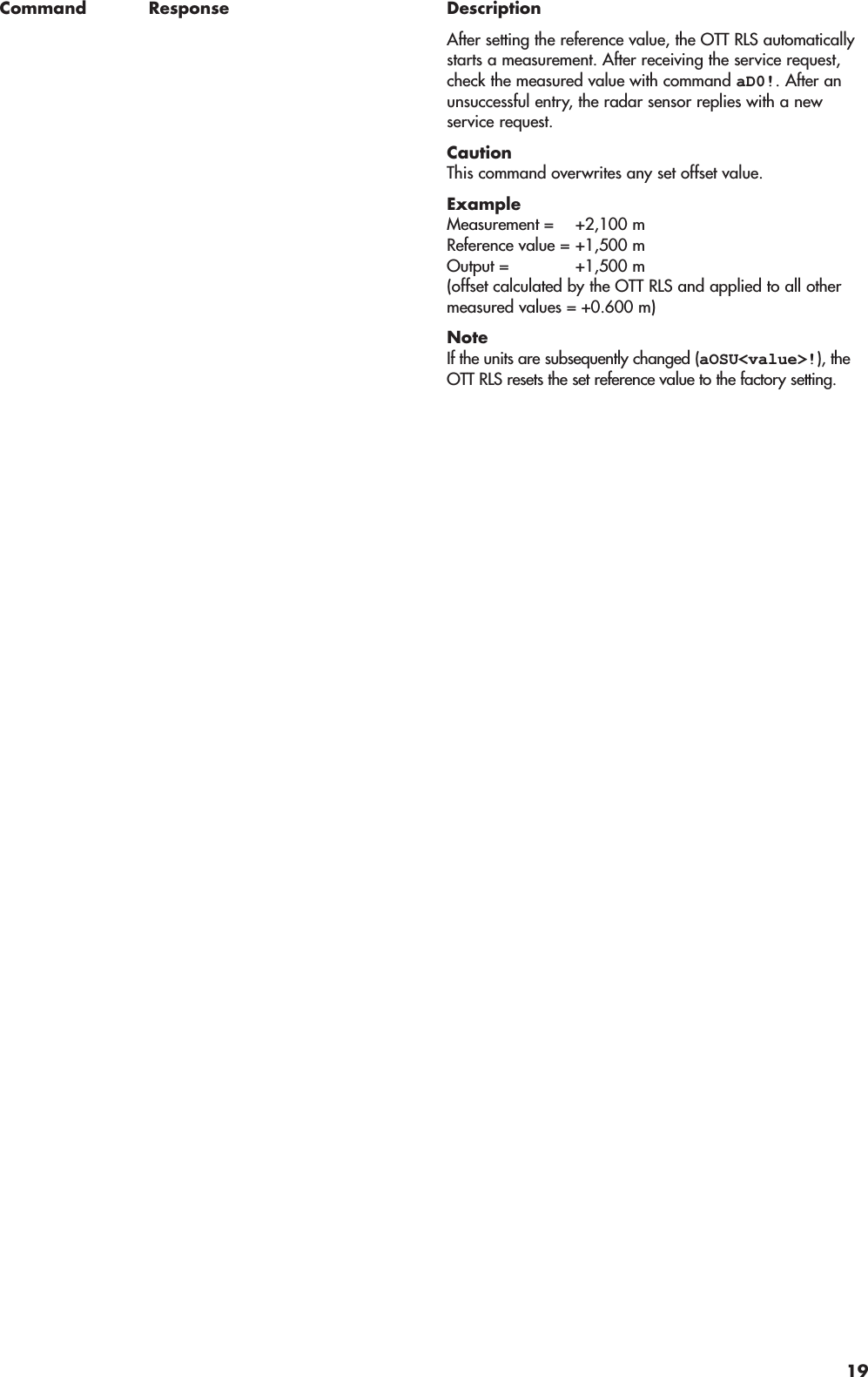
![6 SDI-12 commands and responses6.1 Standard commandsAll SDI-12 standard commands (SDI-12 version 1.1) are implemented in the OTT RLS: The following SDI-12 standard com-mands are relevant for the operation of the OTT RLS:Command Response Descriptiona! a<CR><LF> Confirmation activea– sensor address; factory setting = 0aI! allccccccccmmmmmm……vvvxxxxxx<CR><LF>Send identificationa– sensor addressll – SDI-12 protocol versioncccccccc – manufacturer's identification (company name)mmmmmm – sensor identificationvvv – sensor version (here firmware version)xxxxxx – additional identification (here serial number)OTT RLS response = 011OTT HACH RLS110xxxxxxaAb! b<CR><LF> Change sensor addressa– old sensor addressb– new sensor address?! a<CR><LF> Query sensor address a– sensor addressaM! 1)atttn<CR><LF>and after a max. of 25 secondsa<CR><LF>Start measurementa– sensor addressttt – time in seconds until the sensor hasdetermined the measurement result OTT RLS response = 025 secondsn– number of measured valuesOTT RLS response = 2a<CR><LF> – service requestaD0! a<value1><value2><CR><LF> Send data (after aM!)a– sensor address<value1>– level/distance value:pbbbb.eee [m]2)pbbbbb [cm]2)pbbbbb.ee [ft]2)p– sign (+,–)b– digit (before the decimal point);output without leading zeroes!e– digit after the decimal point;output in the case of invalid measurementvalue: +99999999 (can be changed withadvanced command aOSI!)<value2>– status of the last measurement;for details, see response to command aM1!aMC! 1) atttn<CR><LF>and after a max. of 25 secondsa<CR><LF>Start measurement and request CRC (Cyclic RedundancyCheck). For details, see command aM!. The response to thefollowing aD0! command is extended by a CRC value:a<value1><value2><CRC><CR><LF>aM1! 1) atttn<CR><LF>and immediately afterwardsa<CR><LF>Query status of the last measurementa– sensor addressttt – time in seconds until the sensor makes thestatus available; OTT RLS response = 000n– number of measured valuesOTT RLS response = 2a<CR><LF> – service request1) do not use this command if OTT RLS is connected to a datalogger via the 4 … 20 mA interface! OTT RLS would consequently interrupt the continuous measuringoperation which is needed for the 4 … 20 mA interface.2) Dependent on the units set (advanced command aOSU<value>!)14](https://usermanual.wiki/Ott-Hydromet/RLS252/User-Guide-2379151-Page-14.png)
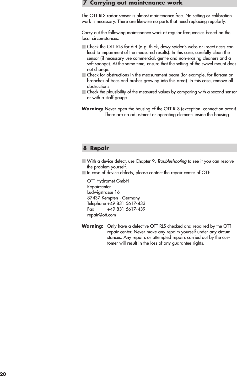
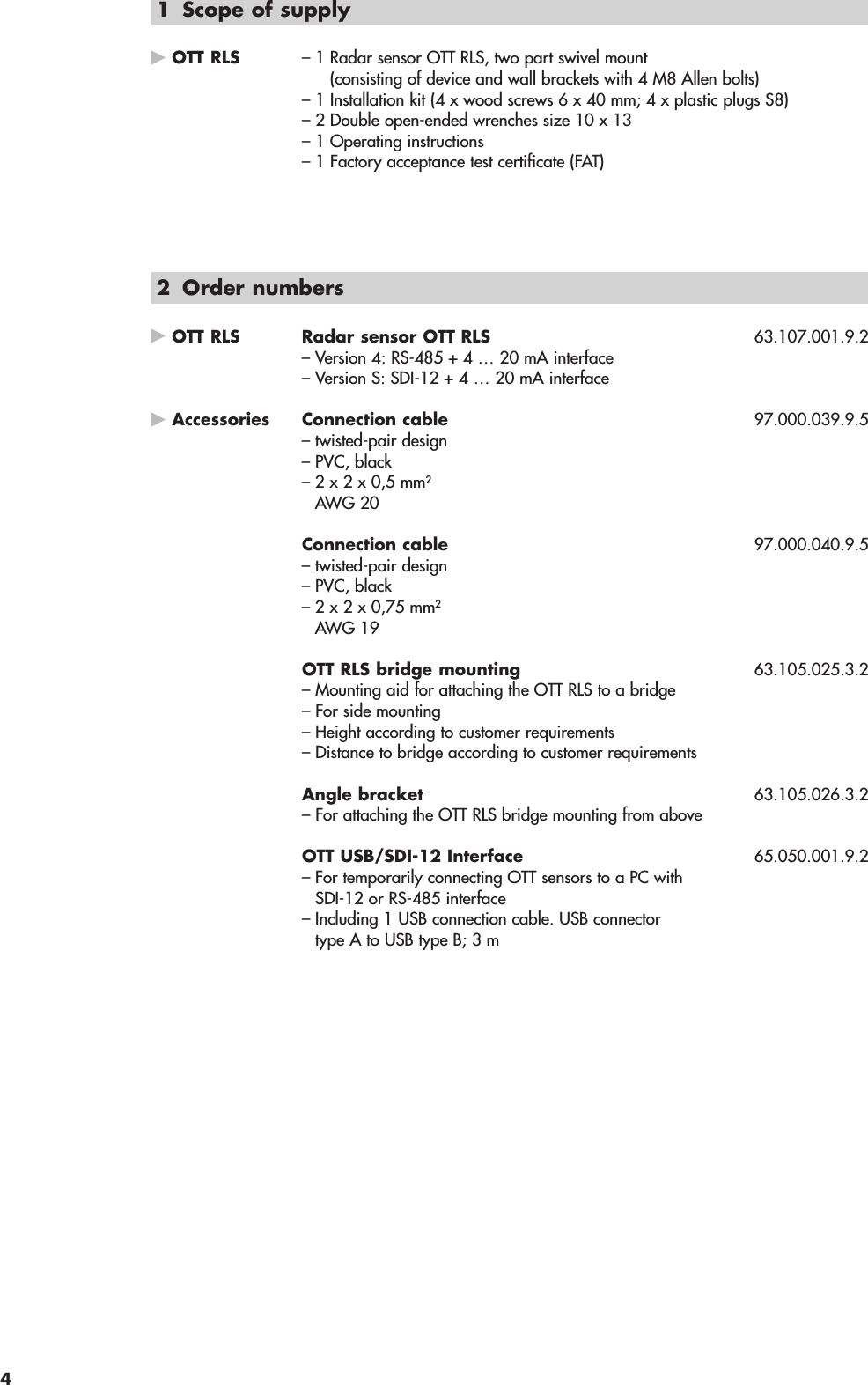
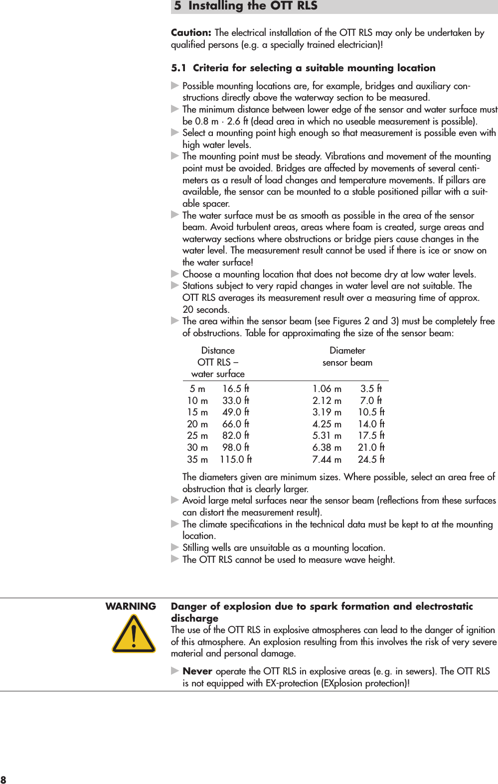
![Command Response DescriptionSet/read measurement mode level or distance measurementaOAA<value>!aOAA!a<value><CR><LF>a<value><CR><LF>Set measuring modeRead out measuring modea– sensor address<value>– +0 = measuring mode Level measurement acti-vated (water level related to a level zero)+1 = measuring mode Distance measurementactivated (distance of OTT RLS ↔watersurface)Factory setting = +1CautionIf entries have been made before changing the measuringmode for the parameters aOAB<value>!, aOAC<value>!,aOPA<value>! or aOPB<value>!, these must be input again!There is no automatic conversion of the parameters entered.Set/read error indicatoraOSI<value>!aOSI!a<value><CR><LF>a<value><CR><LF>Set error indicatorRead error indicatora– sensor address<value> – error indicator that the OTT RLS outputsan invalid measurementpbbbbbbbbp– sign (+,–)b– digitValue range: –99999999 … +99999999Factory setting = +99999999Set/read 4 … 20 mA interface – operating status (activated/deactivated)aOPC<value>aOPC!a<value><CR><LF>a<value><CR><LF>Set operating statusRead operating statusa– sensor address<value> – pb; factory setting = +1p– sign (+)b– digit+0 = interface deactivated+1 = interface activatedUse: the command aOPC+1! is helpful, if e.g. an aM! com-mand unintended has interrupted the continuous operationwhich is needed for the 4 … 20 mA interface.4 … 20 mA interface – setting/reading the lower limitaOPA<value>!aOPA!a<value><CR><LF>a<value><CR><LF>Set lower limitRead lower limita– sensor address<value> – pbbbb.eee [m] *– pbbbb [cm] *– pbbbb.ee [ft] *p– sign (+,–)b– digit (before the decimal point)e– digit after the decimal pointInput/output without leading zeroes!Value range: –9999.999 … +9999.999 *Factory setting = +0.000* Dependent on the units set (aOPF<value>!)NoteIf the units are subsequently changed (aOPF<value>!), theOTT RLS resets the set limit to the factory setting.16](https://usermanual.wiki/Ott-Hydromet/RLS252/User-Guide-2379151-Page-16.png)
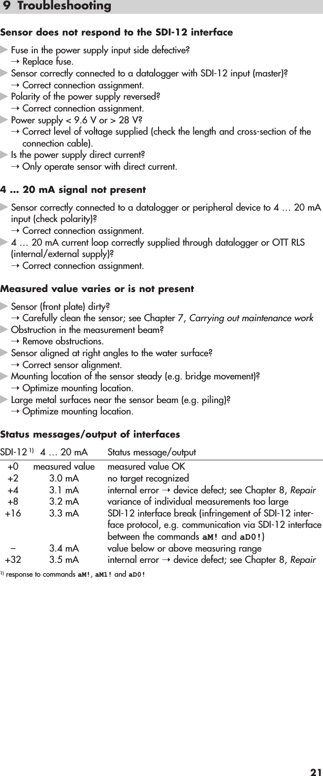
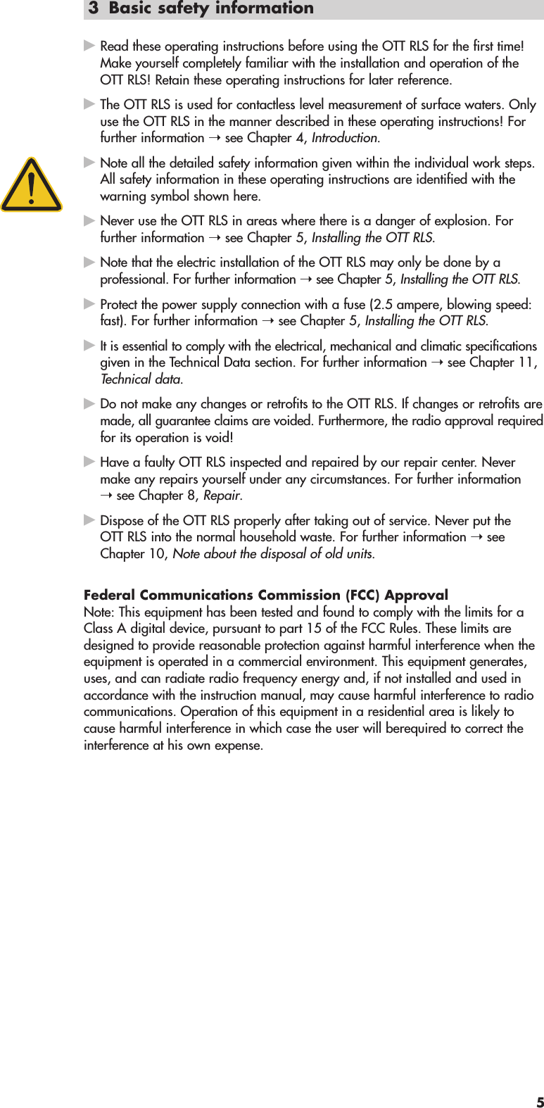
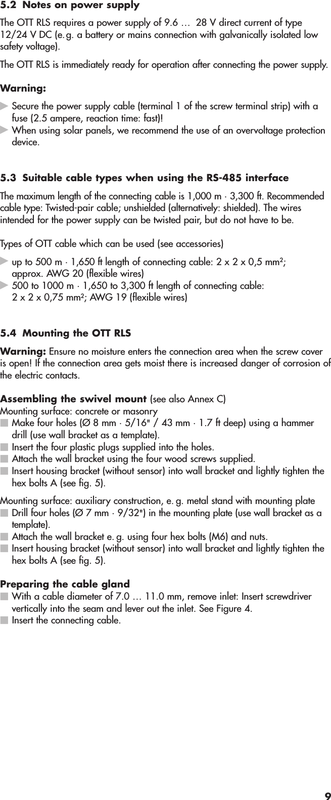
![Fig. 9: Scale the measured valueoutput of the 4 … 20 mA interfacedown to a smaller range.10 m · 33 ft=^ 4 mA(lower limit)15 m · 49 ft=^ 20 mA(upper limit)measuredvalue outputscaled to5 meters · 16 ftvariation ofwater levelFigure is not true to scale0 m · 0 ft =^ 4 mAmin. distance: 0,8 m· 2.6 ft (=^ 4.37 mA)35 m · 115 ft =^ 20 mAwith scalingmeasuredvalue outputwithout scalingCommand Response Description4 … 20 mA interface – setting/reading the upper limitaOPB<value>!aOPB!a<value><CR><LF>a<value><CR><LF>Set upper limitRead upper limita– sensor address<value> – pbbbb.eee [m] *– pbbbb [cm] *– pbbbb.ee [ft] *p– sign (+,–)b– digit (before the decimal point)e– digit after the decimal pointInput/output without leading zeroes!Value range: –9999.999 … +9999.999 *Factory setting = +0.000* Dependent on the units set (aOPF<value>!)NoteIf the units are subsequently changed (aOPF<value>!), theOTT RLS resets the set limit to the factory setting.With the commands setting/reading the lower/upper limit you can scale the available measuring range of an OTT RLS to asmaller range. Where you do not require the whole measuring range, this has the advantage that a higher resolution for the4 … 20 mA interface can be achieved. Example: 16 mA measurement span stands for 5 m · 16 ft of water level changeavailable (e.g. lower limit = +10,000 m · +33,00 ft; upper limit = +15,000 m · +49.00 ft; see Fig. 9).17](https://usermanual.wiki/Ott-Hydromet/RLS252/User-Guide-2379151-Page-17.png)
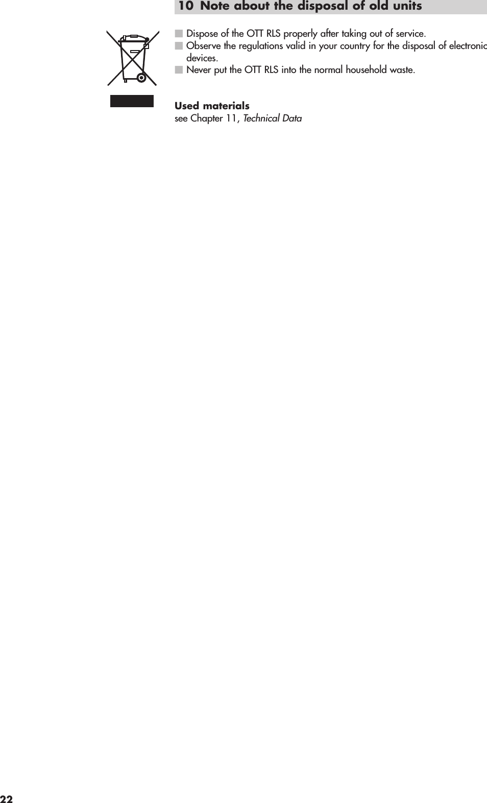
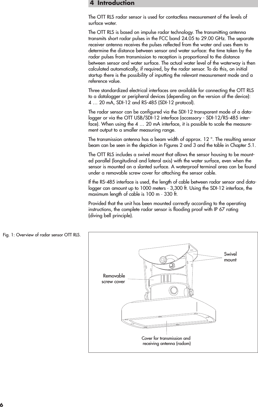
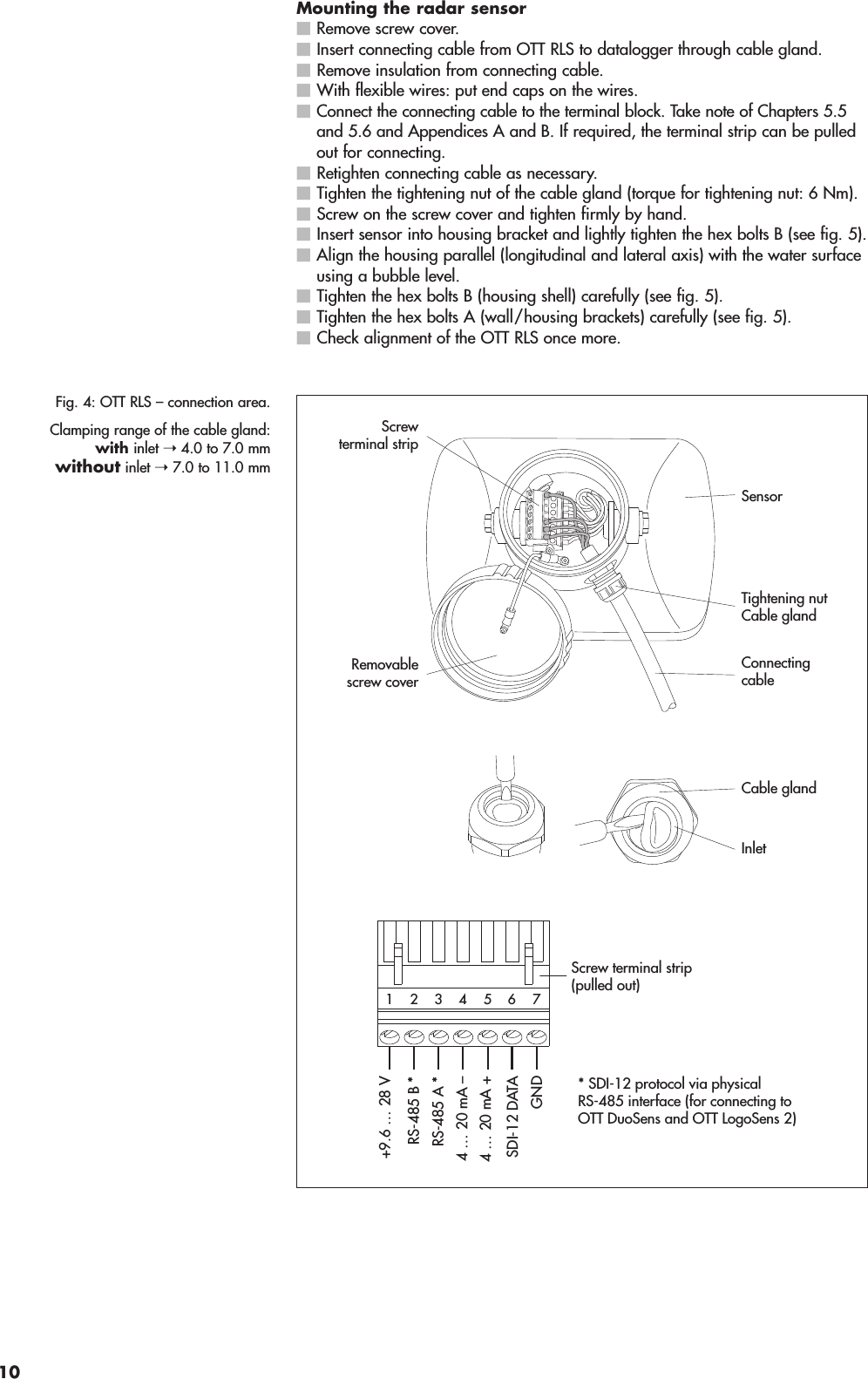
![Command Response DescriptionSDI-12-/RS-485 interface – set/read offset for level/distance measurementaOAB<value>!aOAB!a0251<CR><LF>and after a max. of 25 secondsa<CR><LF>a<value><CR><LFSet offset valueRead offset valuea– sensor address<value> – pbbbb.eee [m] *– pbbbb [cm] *– pbbbb.ee [ft] *p– sign (+,–)b– digit (before the decimal point)e– digit after the decimal pointa<CR><LF> – service requestInput/output without leading zeroes!Value range: –9999.999 … +9999.999 *Factory setting = +0.000With this command, you can add a linear offset (positive/negative) to a level/distance measurement. After setting theoffset value, the OTT RLS automatically starts a measure-ment. After receiving the service request, check the measu-red value with command aD0!. If input is unsuccessful, theradar sensor replies with a new service request.CautionThis command overwrites any set reference value.ExampleMeasurement = +10,040 mOffset = –0,200 mOutput = +9,840 mNoteIf the units are subsequently changed (aOSU<value>!), theOTT RLS resets the set offset value to the factory setting.SDI-12-/RS-485 interface – set/read reference value for the offset for level/distance measurementaOAC<value>!aOAC!a0251<CR><LF>and after a max. of 25 secondsa<CR><LF>a<value><CR><LF>Set reference valueRead reference valuea– sensor address<value> – pbbbb.eee [m] *– pbbbb [cm] *– pbbbb.ee [ft] *p– sign (+,–)b– digit (before the decimal point)e– digit after the decimal pointa<CR><LF> – service requestInput/output without leading zeroes!Value range: –9999.999 … +9999.999 *Factory setting = +0.000With this command, you can establish a reference to a levelzero, for example, by entering a reference value forlevel/distance measurement.* Dependent on the units set (aOSU<value>!)18](https://usermanual.wiki/Ott-Hydromet/RLS252/User-Guide-2379151-Page-18.png)