Ott Hydromet RLS252 Radar Level Sensor User Manual
Ott Hydromet GmbH Radar Level Sensor
user manual
English
Operating instructions
Radar Level Sensor
OTT RLS
We reserve the right to make technical changes and improvements without notice.

3
Table of contents
1 Scope of supply . . . . . . . . . . . . . . . . . . . . . . . . . . . . . . . . . . . . . . . . . . . . . . . . . . . . . . . . . . . . . . . . . . . . . . 4
2 Order numbers . . . . . . . . . . . . . . . . . . . . . . . . . . . . . . . . . . . . . . . . . . . . . . . . . . . . . . . . . . . . . . . . . . . . . . . 4
3 Basic safety information . . . . . . . . . . . . . . . . . . . . . . . . . . . . . . . . . . . . . . . . . . . . . . . . . . . . . . . . . . . . 5
4 Introduction . . . . . . . . . . . . . . . . . . . . . . . . . . . . . . . . . . . . . . . . . . . . . . . . . . . . . . . . . . . . . . . . . . . . . . . . . . 6
5 Installing the OTT RLS . . . . . . . . . . . . . . . . . . . . . . . . . . . . . . . . . . . . . . . . . . . . . . . . . . . . . . . . . . . . . . . 8
5.1 Criteria for selecting a suitable mounting location . . . . . . . . . . . . . . . . . . . . . . . . . . . . . . . . . . . . . . 8
5.2 Notes on power supply . . . . . . . . . . . . . . . . . . . . . . . . . . . . . . . . . . . . . . . . . . . . . . . . . . . . . . . . . . . . . . 9
5.3 Suitable cable types when using the RS-485 interface . . . . . . . . . . . . . . . . . . . . . . . . . . . . . . . . . . 9
5.4 Mounting the OTT RLS . . . . . . . . . . . . . . . . . . . . . . . . . . . . . . . . . . . . . . . . . . . . . . . . . . . . . . . . . . . . . . . 9
5.5 Connecting the OTT RLS to any datalogger using an SDI-12 interface . . . . . . . . . . . . . . . . . . . 11
5.6 Connecting the OTT RLS to any datalogger using a 4 … 20 mA interface . . . . . . . . . . . . . . . . 12
5.7 Determining the maximum load resistance at the 4 … 20 mA interface . . . . . . . . . . . . . . . . . . 12
5.8 Notes on using the 4 … 20 mA interface . . . . . . . . . . . . . . . . . . . . . . . . . . . . . . . . . . . . . . . . . . . . . . 13
5.9 Note on using the RS-485 interface . . . . . . . . . . . . . . . . . . . . . . . . . . . . . . . . . . . . . . . . . . . . . . . . . . . . 13
6 SDI-12 commands and responses . . . . . . . . . . . . . . . . . . . . . . . . . . . . . . . . . . . . . . . . . . . . . . . . . 14
6.1 Standard commands . . . . . . . . . . . . . . . . . . . . . . . . . . . . . . . . . . . . . . . . . . . . . . . . . . . . . . . . . . . . . . . . . 14
6.2 Advanced SDI-12 commands . . . . . . . . . . . . . . . . . . . . . . . . . . . . . . . . . . . . . . . . . . . . . . . . . . . . . . . . . 15
7 Carrying out maintenance work . . . . . . . . . . . . . . . . . . . . . . . . . . . . . . . . . . . . . . . . . . . . . . . . . . . 20
8 Repair . . . . . . . . . . . . . . . . . . . . . . . . . . . . . . . . . . . . . . . . . . . . . . . . . . . . . . . . . . . . . . . . . . . . . . . . . . . . . . . . . 20
9 Troubleshooting . . . . . . . . . . . . . . . . . . . . . . . . . . . . . . . . . . . . . . . . . . . . . . . . . . . . . . . . . . . . . . . . . . . . . . 21
10 Note about the disposal of old units . . . . . . . . . . . . . . . . . . . . . . . . . . . . . . . . . . . . . . . . . . . . . . 22
11 Technical Data . . . . . . . . . . . . . . . . . . . . . . . . . . . . . . . . . . . . . . . . . . . . . . . . . . . . . . . . . . . . . . . . . . . . . . . . 23
Annex A – Connecting the OTT RLS to LogoSens 2 or DuoSens
using an SDI-12 or RS-485 interface . . . . . . . . . . . . . . . . . . . . . . . . . . . . . . . . . . . . . 25
Annex B – Connecting the OTT RLS to LogoSens 2 or DuoSens
using a 4 … 20 mA interface . . . . . . . . . . . . . . . . . . . . . . . . . . . . . . . . . . . . . . . . . . . . . . 28
Annex C – Dimensions of wall bracket/position of fixing bores . . . . . . . . . . . . . . . . . . . 30
Annex D – Declaration of Conformity . . . . . . . . . . . . . . . . . . . . . . . . . . . . . . . . . . . . . . . . . . . . . . . . . . 31
Annex E – Radio Approval USA: Grant of Equipment Authorization . . . . . . . . . . . . . . . 32

1 Scope of supply
OTT RLS – 1 Radar sensor OTT RLS, two part swivel mount
(consisting of device and wall brackets with 4 M8 Allen bolts)
– 1 Installation kit (4 x wood screws 6 x 40 mm; 4 x plastic plugs S8)
– 2 Double open-ended wrenches size 10 x 13
– 1 Operating instructions
– 1 Factory acceptance test certificate (FAT)
2 Order numbers
OTT RLS Radar sensor OTT RLS 63.107.001.9.2
– Version 4: RS-485 + 4 … 20 mA interface
– Version S: SDI-12 + 4 … 20 mA interface
Accessories Connection cable 97.000.039.9.5
– twisted-pair design
– PVC, black
– 2 x 2 x 0,5 mm2
AWG 20
Connection cable 97.000.040.9.5
– twisted-pair design
– PVC, black
– 2 x 2 x 0,75 mm2
AWG 19
OTT RLS bridge mounting 63.105.025.3.2
– Mounting aid for attaching the OTT RLS to a bridge
– For side mounting
– Height according to customer requirements
– Distance to bridge according to customer requirements
Angle bracket 63.105.026.3.2
– For attaching the OTT RLS bridge mounting from above
OTT USB/SDI-12 Interface 65.050.001.9.2
– For temporarily connecting OTT sensors to a PC with
SDI-12 or RS-485 interface
– Including 1 USB connection cable. USB connector
type A to USB type B; 3 m
4

3 Basic safety information
Read these operating instructions before using the OTT RLS for the first time!
Make yourself completely familiar with the installation and operation of the
OTT RLS! Retain these operating instructions for later reference.
The OTT RLS is used for contactless level measurement of surface waters. Only
use the OTT RLS in the manner described in these operating instructions! For
further information ➝ see Chapter 4, Introduction.
Note all the detailed safety information given within the individual work steps.
All safety information in these operating instructions are identified with the
warning symbol shown here.
Never use the OTT RLS in areas where there is a danger of explosion. For
further information ➝ see Chapter 5, Installing the OTT RLS.
Note that the electric installation of the OTT RLS may only be done by a
professional. For further information ➝ see Chapter 5, Installing the OTT RLS.
Protect the power supply connection with a fuse (2.5 ampere, blowing speed:
fast). For further information ➝ see Chapter 5, Installing the OTT RLS.
It is essential to comply with the electrical, mechanical and climatic specifications
given in the Technical Data section. For further information ➝ see Chapter 11,
Technical data.
Do not make any changes or retrofits to the OTT RLS. If changes or retrofits are
made, all guarantee claims are voided. Furthermore, the radio approval required
for its operation is void!
Have a faulty OTT RLS inspected and repaired by our repair center. Never
make any repairs yourself under any circumstances. For further information
➝ see Chapter 8, Repair.
Dispose of the OTT RLS properly after taking out of service. Never put the
OTT RLS into the normal household waste. For further information ➝ see
Chapter 10, Note about the disposal of old units.
Federal Communications Commission (FCC) Approval
Note: This equipment has been tested and found to comply with the limits for a
Class A digital device, pursuant to part 15 of the FCC Rules. These limits are
designed to provide reasonable protection against harmful interference when the
equipment is operated in a commercial environment. This equipment generates,
uses, and can radiate radio frequency energy and, if not installed and used in
accordance with the instruction manual, may cause harmful interference to radio
communications. Operation of this equipment in a residential area is likely to
cause harmful interference in which case the user will berequired to correct the
interference at his own expense.
5
4 Introduction
The OTT RLS radar sensor is used for contactless measurement of the levels of
surface water.
The OTT RLS is based on impulse radar technology. The transmitting antenna
transmits short radar pulses in the FCC band 24.05 to 29.00 GHz. The separate
receiver antenna receives the pulses reflected from the water and uses them to
determine the distance between sensor and water surface: the time taken by the
radar pulses from transmission to reception is proportional to the distance
between sensor and water surface. The actual water level of the waterway is then
calculated automatically, if required, by the radar sensor. To do this, on initial
startup there is the possibility of inputting the relevant measurement mode and a
reference value.
Three standardized electrical interfaces are available for connecting the OTT RLS
to a datalogger or peripheral devices (depending on the version of the device):
4 … 20 mA, SDI-12 and RS-485 (SDI-12 protocol).
The radar sensor can be configured via the SDI-12 transparent mode of a data-
logger or via the OTT USB/SDI-12 interface (accessory - SDI-12/RS-485 inter-
face). When using the 4 … 20 mA interface, it is possible to scale the measure-
ment output to a smaller measuring range.
The transmission antenna has a beam width of approx. 12 °. The resulting sensor
beam can be seen in the depiction in Figures 2 and 3 and the table in Chapter 5.1.
The OTT RLS includes a swivel mount that allows the sensor housing to be mount-
ed parallel (longitudinal and lateral axis) with the water surface, even when the
sensor is mounted on a slanted surface. A waterproof terminal area can be found
under a removable screw cover for attaching the sensor cable.
If the RS-485 interface is used, the length of cable between radar sensor and data -
logger can amount up to 1000 meters · 3,300 ft. Using the SDI-12 interface, the
maximum length of cable is 100 m · 330 ft.
Provided that the unit has been mounted correctly according to the operating
instructions, the complete radar sensor is flooding proof with IP 67 rating
(diving bell principle).
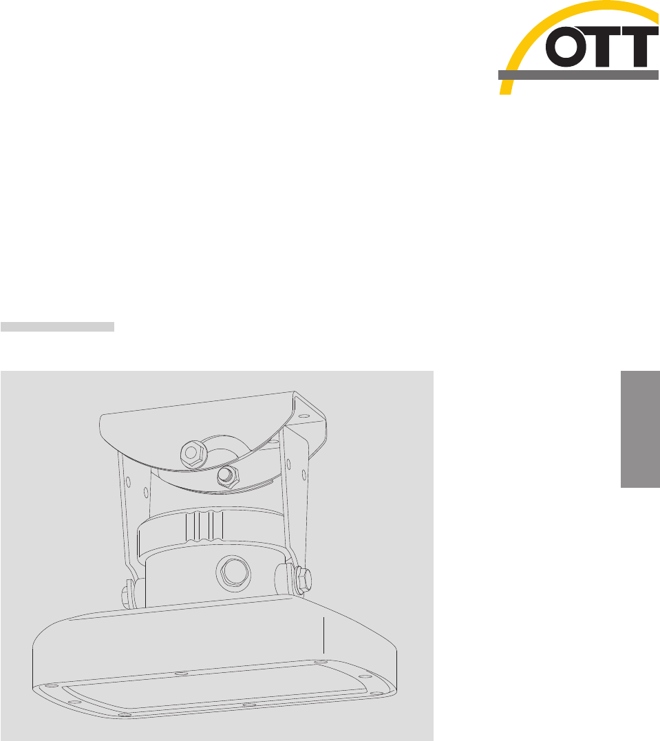
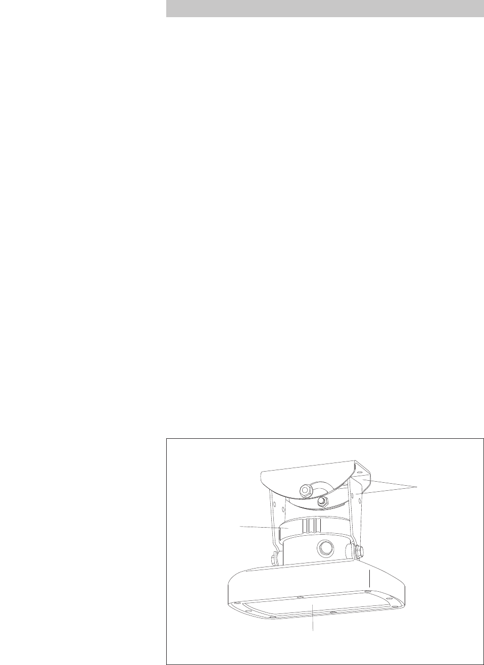
Fig. 1: Overview of radar sensor OTT RLS.
Cover for transmission and
receiving antenna (radom)
Swivel
mount
Removable
screw cover
6
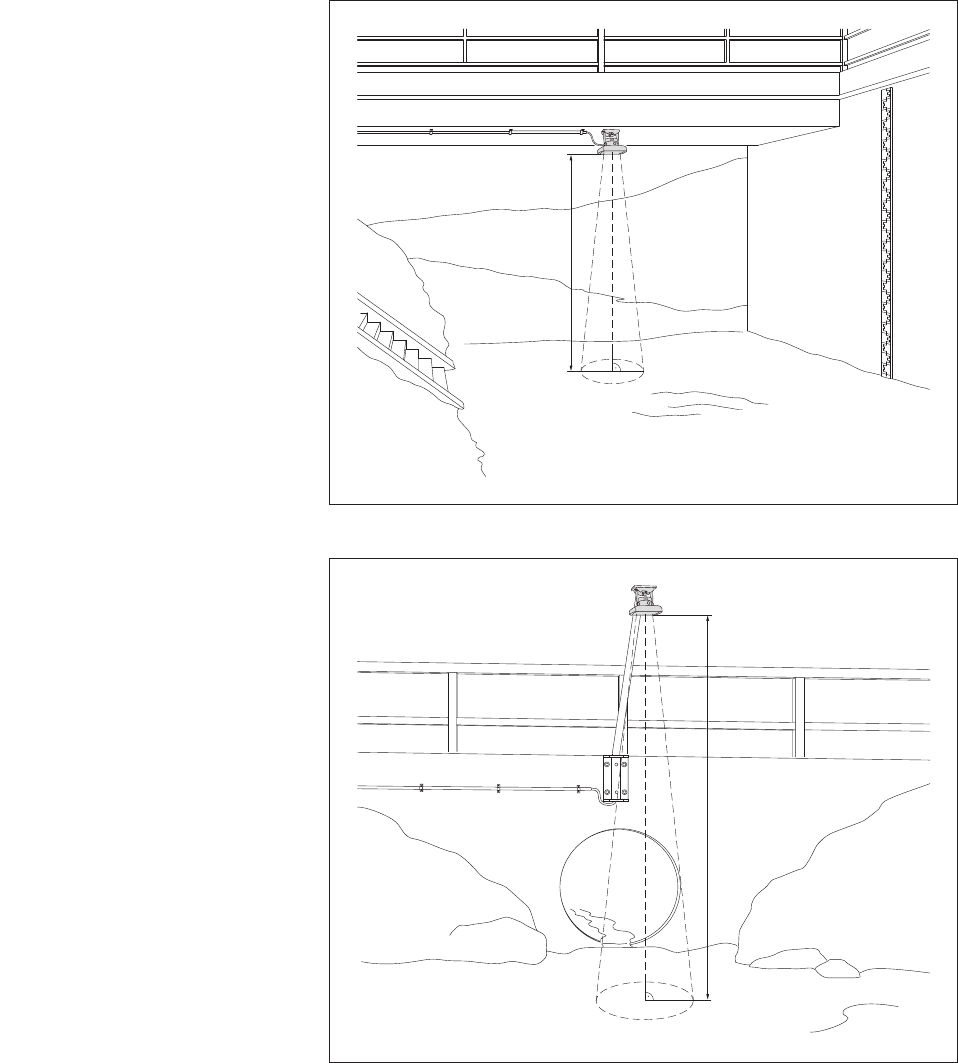
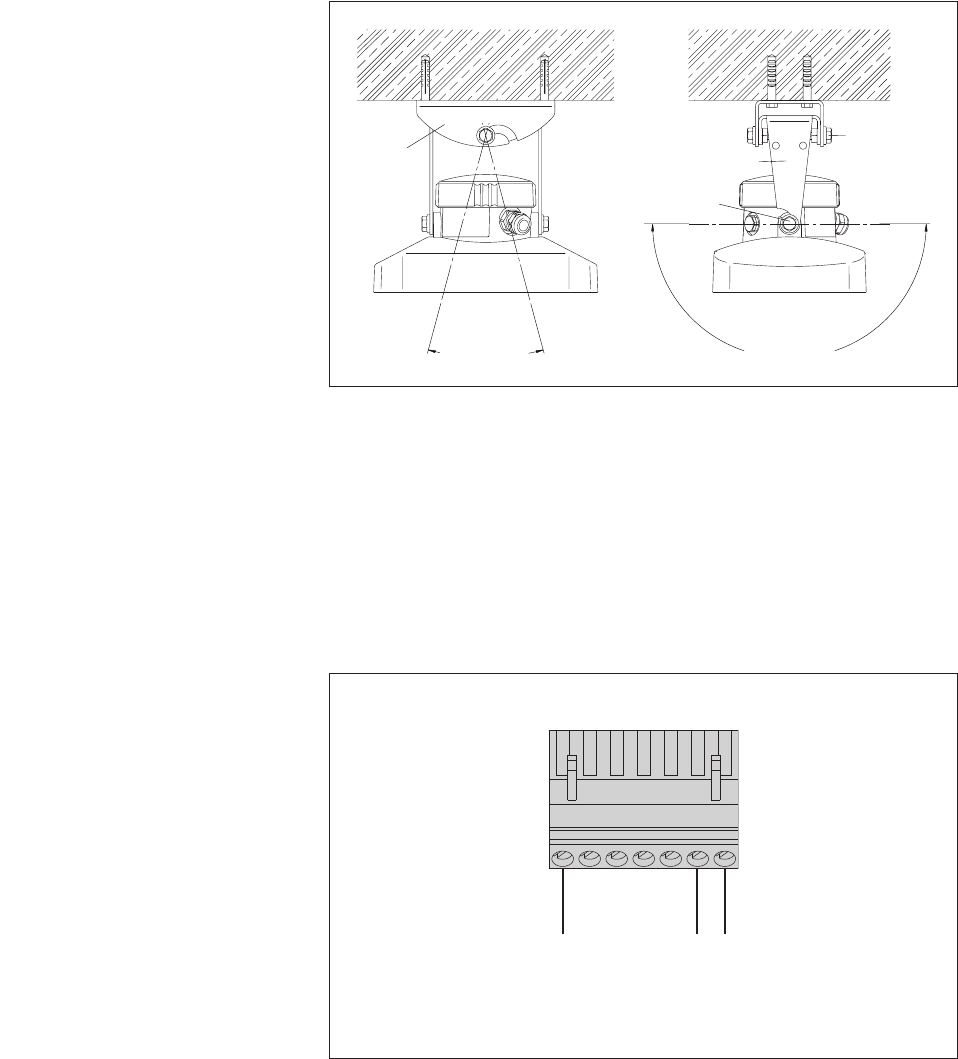
Fig. 3: Application example 2:
Mounting the OTT RLS on an
auxiliary construction, e.g. metal
stand with mounting plate.
OTT RLS
Sensor beam
Distance
Fig. 2: Application example 1:
Mounting the OTT RLS on a bridge.
The projection of the sensor beam onto
the water surface is virtually round.
OTT RLS
Sensor beam
Distance
7

5 Installing the OTT RLS
Caution: The electrical installation of the OTT RLS may only be undertaken by
qualified persons (e.g. a specially trained electrician)!
5.1 Criteria for selecting a suitable mounting location
Possible mounting locations are, for example, bridges and auxiliary con -
structions directly above the waterway section to be measured.
The minimum distance between lower edge of the sensor and water surface must
be 0.8 m · 2.6 ft (dead area in which no useable measurement is possible).
Select a mounting point high enough so that measurement is possible even with
high water levels.
The mounting point must be steady. Vibrations and movement of the mounting
point must be avoided. Bridges are affected by movements of several centi -
meters as a result of load changes and temperature movements. If pillars are
available, the sensor can be mounted to a stable positioned pillar with a suit-
able spacer.
The water surface must be as smooth as possible in the area of the sensor
beam. Avoid turbulent areas, areas where foam is created, surge areas and
waterway sections where obstructions or bridge piers cause changes in the
water level. The measurement result cannot be used if there is ice or snow on
the water surface!
Choose a mounting location that does not become dry at low water levels.
Stations subject to very rapid changes in water level are not suitable. The
OTT RLS averages its measurement result over a measuring time of approx.
20 seconds.
The area within the sensor beam (see Figures 2 and 3) must be completely free
of obstructions. Table for approximating the size of the sensor beam:
Distance Diameter
OTT RLS – sensor beam
water surface
5 m 16.5 ft 1.06 m 3.5 ft
10 m 33.0 ft 2.12 m 7.0 ft
15 m 49.0 ft 3.19 m 10.5 ft
20 m 66.0 ft 4.25 m 14.0 ft
25 m 82.0 ft 5.31 m 17.5 ft
30 m 98.0 ft 6.38 m 21.0 ft
35 m 115.0 ft 7.44 m 24.5 ft
The diameters given are minimum sizes. Where possible, select an area free of
obstruction that is clearly larger.
Avoid large metal surfaces near the sensor beam (reflections from these sur faces
can distort the measurement result).
The climate specifications in the technical data must be kept to at the mounting
location.
Stilling wells are unsuitable as a mounting location.
The OTT RLS cannot be used to measure wave height.
WARNING Danger of explosion due to spark formation and electrostatic
discharge
The use of the OTT RLS in explosive atmospheres can lead to the danger of ignition
of this atmosphere. An explosion resulting from this involves the risk of very severe
material and personal damage.
Never operate the OTT RLS in explosive areas (e.g. in sewers). The OTT RLS
is not equipped with EX-protection (EXplosion protection)!
8
5.2 Notes on power supply
The OTT RLS requires a power supply of 9.6 … 28 V direct current of type
12/24 V DC (e.g. a battery or mains connection with galvanically isolated low
safety voltage).
The OTT RLS is immediately ready for operation after connecting the power supply.
Warning:
Secure the power supply cable (terminal 1 of the screw terminal strip) with a
fuse (2.5 ampere, reaction time: fast)!
When using solar panels, we recommend the use of an overvoltage protection
device.
5.3 Suitable cable types when using the RS-485 interface
The maximum length of the connecting cable is 1,000 m · 3,300 ft. Recommended
cable type: Twisted-pair cable; unshielded (alternatively: shielded). The wires
intended for the power supply can be twisted pair, but do not have to be.
Types of OTT cable which can be used (see accessories)
up to 500 m · 1,650 ft length of connecting cable: 2 x 2 x 0,5 mm2;
approx. AWG 20 (flexible wires)
500 to 1000 m · 1,650 to 3,300 ft length of connecting cable:
2 x 2 x 0,75 mm2; AWG 19 (flexible wires)
5.4 Mounting the OTT RLS
Warning: Ensure no moisture enters the connection area when the screw cover
is open! If the connection area gets moist there is increased danger of corrosion of
the electric contacts.
Assembling the swivel mount (see also Annex C)
Mounting surface: concrete or masonry
Make four holes (Ø 8 mm · 5/16"/ 43 mm · 1.7 ft deep) using a hammer
drill (use wall bracket as a template).
Insert the four plastic plugs supplied into the holes.
Attach the wall bracket using the four wood screws supplied.
Insert housing bracket (without sensor) into wall bracket and lightly tighten the
hex bolts A (see fig. 5).
Mounting surface: auxiliary construction, e. g. metal stand with mounting plate
Drill four holes (Ø 7 mm · 9/32") in the mounting plate (use wall bracket as a
template).
Attach the wall bracket e. g. using four hex bolts (M6) and nuts.
Insert housing bracket (without sensor) into wall bracket and lightly tighten the
hex bolts A (see fig. 5).
Preparing the cable gland
With a cable diameter of 7.0 … 11.0 mm, remove inlet: Insert screwdriver
vertically into the seam and lever out the inlet. See Figure 4.
Insert the connecting cable.
9
Mounting the radar sensor
Remove screw cover.
Insert connecting cable from OTT RLS to datalogger through cable gland.
Remove insulation from connecting cable.
With flexible wires: put end caps on the wires.
Connect the connecting cable to the terminal block. Take note of Chapters 5.5
and 5.6 and Appendices A and B. If required, the terminal strip can be pulled
out for connecting.
Retighten connecting cable as necessary.
Tighten the tightening nut of the cable gland (torque for tightening nut: 6 Nm).
Screw on the screw cover and tighten firmly by hand.
Insert sensor into housing bracket and lightly tighten the hex bolts B (see fig. 5).
Align the housing parallel (longitudinal and lateral axis) with the water surface
using a bubble level.
Tighten the hex bolts B (housing shell) carefully (see fig. 5).
Tighten the hex bolts A (wall/housing brackets) carefully (see fig. 5).
Check alignment of the OTT RLS once more.
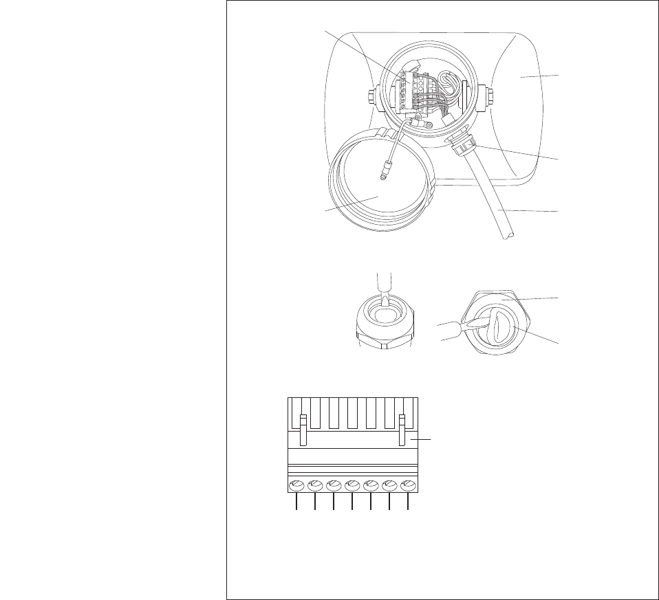
Fig. 4: OTT RLS – connection area.
Clamping range of the cable gland:
with inlet ➝ 4.0 to 7.0 mm
without inlet ➝ 7.0 to 11.0 mm
Removable
screw cover
Tightening nut
Cable gland
Screw
terminal strip
Sensor
Cable gland
Inlet
Connecting
cable
4 … 20 mA +
4 … 20 mA –
GND
RS-485 B *
RS-485 A *
SDI-12 DATA
* SDI-12 protocol via physical
RS-485 interface (for connecting to
OTT DuoSens and OTT LogoSens 2)
542 3176
+9.6 … 28 V
Screw terminal strip
(pulled out)
10
Warning: The alignment of the sensor parallel to the water surface must be
carried out as accurately as possible!
➝Deviation from the parallel alignment leads to a linearity error.
➝Incorrect alignment of > 4 ° can lead to a function failure of the OTT RLS
(depending on the other operating parameters such as distance between
lower sensor edge and water surface).
5.5 Connecting the OTT RLS to any datalogger using an SDI-12
interface
Connect the OTT RLS to an SDI-12 input of the datalogger. Follow the datalog-
ger handbook as you do this. Refer to Figure 6 for the connection assignments
of the OTT RLS. The maximum length of the connecting cable is 100 m · 330 ft.
Recommended wire cross-section: 0.5 mm2· AWG 20. With separate voltage
supply and point-to-point connection (no SDI-12 bus operation) a cable length
of up to 300 m · 985 ft is possible.
You will find the SDI-12 commands for the OTT RLS in Chapter 6, SDI-12 com-
mands and responses.
Fig. 6: Connecting the OTT RLS to any
datalogger using an SDI-12 interface.
(Standard SDI-12 wiring via
three-wire connecting cable).
+12 V
SDI-12 GND
SDI-12 DATA
542 3176
RLS
Fig. 5: OTT RLS – rotation
range of swivel mount.
max. ±90 °
Hex
bolt A
Hex bolt B
Wall
bracket Housing bracket
max. ±15 °
11
5.6 Connecting the OTT RLS to any datalogger using
a 4 … 20 mA interface
Connect the OTT RLS to a 4 … 20 mA input of the datalogger. Follow the data-
logger handbook when doing this. Refer to Figure 7 for the connection assign-
ments of the OTT RLS. The maximum connecting cable length/recommended
wire cross-section: depending on the amount of voltage supply and the size of
the burden (load resistor). Please note that the ohmic resistance of the connect-
ing cable together with the eventually existing burden do not exceed the max.
allowed load resistance (see Chapter 5.7)!
Caution: the 4 … 20 mA interface of the OTT RLS is passive. If needed the sup-
ply for the current loop must be injected by wire-linking the supply voltage.
Tipp: To connect the OTT RLS using the 4 … 20 mA interface, a 4-wire cable is
required. If the OTT RLS is also to be configurable via SDI-12 commands, ➝use
5-wire (cable length up to 100 m) or 6-wire cable (cable length up to 1000 m).
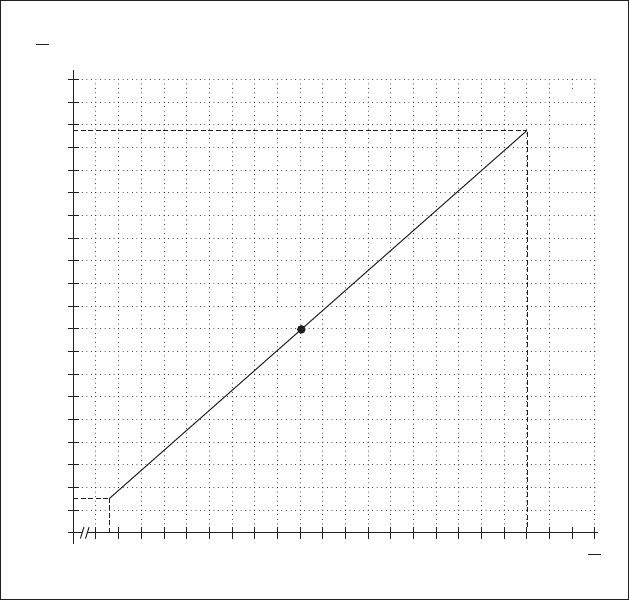
5.7 Determining the maximum load resistance at the 4 … 20 mA
interface
The load resistance (burden + ohmic resistance of the connection cable) connected
to the OTT RLS must not exceed a specific maximum value. This value depends on
the level of the supply voltage of the OTT RLS. If the load resistance is greater, the
output current can no longer be evaluated. Smaller load resistances are allowed.
Read off the maximum load resistance for your power supply from the follow-
ing diagram.
Example: Power supply 18 volt ➝max. load resistance 450 ohm.
The OTT RLS delivers an output current corresponding to the measured value
for a load resistance of up to 450 ohm.
Dimension the connected electrical circuit accordingly. Check the input resis-
tance of the connected peripheral device for this purpose.
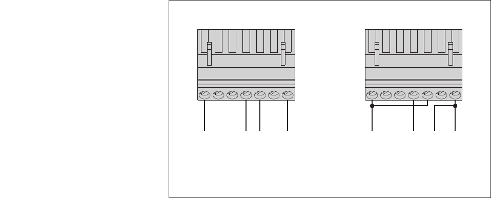
Fig. 7: Examples for connecting the
OTT RLS to any datalogger via the
4 … 20 mA interface.
Left: supplying the loop
current from the datalogger.
Right: supplying the loop current to the
OTT RLS supply voltage using wire bridges.
+9,6 … 28 V
GND
4 … 20 mA +
4 … 20 mA –
GND
4 … 20 mA +
4 … 20 mA –
5
42 3176
RLS
+9,6 … 28 V
5
42 3176
RLS
12
5.8 Notes on using the 4 … 20 mA interface
Switching behaviour of the 4 … 20 mA interface
After switching on the supply voltage, it takes approx. 20 seconds until the
loop current takes on a value proportional to the water level. (In the first
20 seconds, the loop current is between 3 and 4 mA.) Afterwards, the radar
sensor updates the loop current every 20 seconds.
Caution: The 4 … 20 mA interface cannot be used parallel to the SDI-12 or
RS-485 interfaces. (Exception: temporary configuration of the OTT RLS with
SDI-12 commands.)
5.9 Note on using the RS-485 interface
The RS-485 interface can only be used with an OTT datalogger. In this case, the
transmission protocol via the physical RS-485 interface is the SDI-12 protocol.
Connect OTT RLS via the RS-485 interface to the OTT LogoSens/DuoSens ➝see
see Appendix A, version B.
10 15 20 25 30 U
V
100
0
200
300
400
500
600
700
800
R
Ω
900
1000
Example
Figure 8: Diagram to determine
the maximum load resistance as
a function of the power supply.
Minimum power supply: 9.6 V
Maximum power supply: 28 V
Resistor tolerance: 0.1 %/15 ppm
(burden = load resistor).
13

6 SDI-12 commands and responses
6.1 Standard commands
All SDI-12 standard commands (SDI-12 version 1.1) are implemented in the OTT RLS: The following SDI-12 standard com-
mands are relevant for the operation of the OTT RLS:
Command Response Description
a! a<CR><LF> Confirmation active
a– sensor address; factory setting = 0
aI! allccccccccmmmmmm…
…vvvxxxxxx<CR><LF>
Send identification
a– sensor address
ll – SDI-12 protocol version
cccccccc – manufacturer's identification (company name)
mmmmmm – sensor identification
vvv – sensor version (here firmware version)
xxxxxx – additional identification (here serial number)
OTT RLS response = 011OTT HACH RLS110xxxxxx
aAb! b<CR><LF> Change sensor address
a– old sensor address
b– new sensor address
?! a<CR><LF> Query sensor address
a– sensor address
aM! 1)atttn<CR><LF>
and after a max. of 25 seconds
a<CR><LF>
Start measurement
a– sensor address
ttt – time in seconds until the sensor has
determined the measurement result
OTT RLS response = 025 seconds
n– number of measured values
OTT RLS response = 2
a<CR><LF> – service request
aD0! a<value1><value2><CR><LF> Send data (after aM!)
a– sensor address
<value1>
– level/distance value:
pbbbb.eee [m]2)
pbbbbb [cm]2)
pbbbbb.ee [ft]2)
p– sign (+,–)
b– digit (before the decimal point);
output without leading zeroes!
e– digit after the decimal point;
output in the case of invalid measurement
value: +99999999 (can be changed with
advanced command aOSI!)
<value2>
– status of the last measurement;
for details, see response to command aM1!
aMC! 1) atttn<CR><LF>
and after a max. of 25 seconds
a<CR><LF>
Start measurement and request CRC (Cyclic Redundancy
Check). For details, see command aM!. The response to the
following aD0! command is extended by a CRC value:
a<value1><value2><CRC><CR><LF>
aM1! 1) atttn<CR><LF>
and immediately afterwards
a<CR><LF>
Query status of the last measurement
a– sensor address
ttt – time in seconds until the sensor makes the
status available; OTT RLS response = 000
n– number of measured values
OTT RLS response = 2
a<CR><LF> – service request
1) do not use this command if OTT RLS is connected to a datalogger via the 4 … 20 mA interface! OTT RLS would consequently interrupt the continuous measuring
operation which is needed for the 4 … 20 mA interface.
2) Dependent on the units set (advanced command aOSU<value>!)
14

More information on the SDI-12 standard commands can be found in the document SDI-12; A Serial-Digital Interface Standard
for Microprocessor-Based Sensors; Version 1.1 (see Internet page www.sdi-12.org).
6.2 Advanced SDI-12 commands
All advanced SDI-12 commands begin with an "O" for OTT. With these commands, it is possible to configure the OTT RLS
using the transparent mode of a datalogger or with the OTT USB/SDI-12 interface (accessory).
Command Response Description
Query firmware version
aOOV! accccccc<CR><LF> Query the firmware version of the OTT RLS.
a– sensor address
ccccccc – firmware version. Example: V1.10.0
4 … 20 mA interface – set/read units for measurements
aOPF<value>!
aOPF
a<value><CR><LF>
a<value><CR><LF>
Set units for commands aOPA<value>! and
aOPB<value>!.
Read unit for commands aOPA<value! and
aOPB<value>!.
a– sensor address
<value> – +0 = m
+1 = cm
+2 = ft
SDI-12-/RS-485 interface – set/read units for measurements
aOSU<value>!
aOSU!
a<value><CR><LF>
a<value><CR><LF>
Set units for commands aM!; aMC!; aOAB<value>! and
aOAC<value>!.
Read unit for commands aM!; aMC!; aOAB<value>! and
aOAC<value>!
a– sensor address
<value> – +0 = m
+1 = cm
+2 = ft
Caution
Changing the unit deletes any set reference or offset value!
Command Response Description
aD0! a<value1><value2><CR><LF> Send data (after aM1!)
a– sensor address
<value1>
– status of the last measurement
+0 = measured value O.K.
+2 = no target recognised
+4 = internal error ➝ device fault.
See Chapter 8, Repair
+8 = variance of individual measurements too
large
+16 = SDI-12 interface interruption (breach of
the SDI-12 interface protocol, e.g. com-
munication with the SDI-12 interface
between commands aM! and aD0!)
+32 = internal error (temperature calibration
values missing) ➝ device fault. See
Chapter 8, Repair
<value2>
– signal-to-noise ratio in dB. Value ≥ 15 dB =
good signal quality (well-chosen mounting
location and parallel alignment)
aMC1! atttn<CR><LF>
and immediately afterwards
a<CR><LF>
Query the status of the last measurement and request CRC
(Cyclic Redundancy Check). For details, see command aM!.
The response to the following aD0! command is extended by
a CRC value: a<value1><value2><CRC><CR><LF>
15

Command Response Description
Set/read measurement mode level or distance measurement
aOAA<value>!
aOAA!
a<value><CR><LF>
a<value><CR><LF>
Set measuring mode
Read out measuring mode
a– sensor address
<value>
– +0 = measuring mode Level measurement acti-
vated (water level related to a level zero)
+1 = measuring mode Distance measurement
activated (distance of OTT RLS ↔water
surface)
Factory setting = +1
Caution
If entries have been made before changing the measuring
mode for the parameters aOAB<value>!, aOAC<value>!,
aOPA<value>! or aOPB<value>!, these must be input again!
There is no automatic conversion of the parameters entered.
Set/read error indicator
aOSI<value>!
aOSI!
a<value><CR><LF>
a<value><CR><LF>
Set error indicator
Read error indicator
a– sensor address
<value> – error indicator that the OTT RLS outputs
an invalid measurement
pbbbbbbbb
p– sign (+,–)
b– digit
Value range: –99999999 … +99999999
Factory setting = +99999999
Set/read 4 … 20 mA interface – operating status (activated/deactivated)
aOPC<value>
aOPC!
a<value><CR><LF>
a<value><CR><LF>
Set operating status
Read operating status
a– sensor address
<value> – pb; factory setting = +1
p– sign (+)
b– digit
+0 = interface deactivated
+1 = interface activated
Use: the command aOPC+1! is helpful, if e.g. an aM! com-
mand unintended has interrupted the continuous operation
which is needed for the 4 … 20 mA interface.
4 … 20 mA interface – setting/reading the lower limit
aOPA<value>!
aOPA!
a<value><CR><LF>
a<value><CR><LF>
Set lower limit
Read lower limit
a– sensor address
<value> – pbbbb.eee [m] *
– pbbbb [cm] *
– pbbbb.ee [ft] *
p– sign (+,–)
b– digit (before the decimal point)
e– digit after the decimal point
Input/output without leading zeroes!
Value range: –9999.999 … +9999.999 *
Factory setting = +0.000
* Dependent on the units set (aOPF<value>!)
Note
If the units are subsequently changed (aOPF<value>!), the
OTT RLS resets the set limit to the factory setting.
16
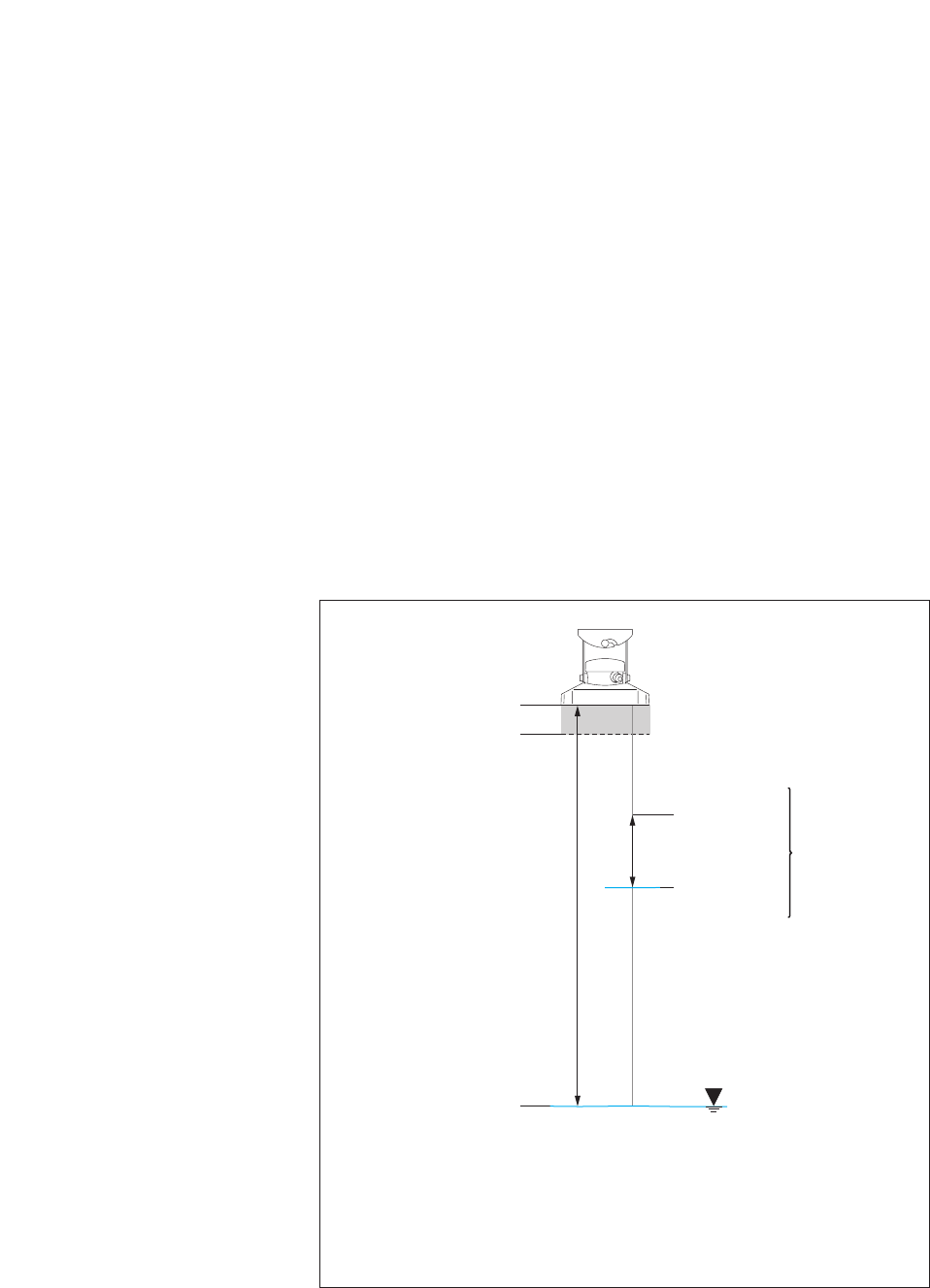
Fig. 9: Scale the measured value
output of the 4 … 20 mA interface
down to a smaller range.
10 m · 33 ft
=
^ 4 mA
(lower limit)
15 m · 49 ft
=
^ 20 mA
(upper limit)
measured
value output
scaled to
5 meters · 16 ft
variation of
water level
Figure is not true to scale
0 m · 0 ft =
^ 4 mA
min. distance: 0,8 m
· 2.6 ft (=
^ 4.37 mA)
35 m · 115 ft =
^ 20 mA
with scaling
measured
value output
without scaling
Command Response Description
4 … 20 mA interface – setting/reading the upper limit
aOPB<value>!
aOPB!
a<value><CR><LF>
a<value><CR><LF>
Set upper limit
Read upper limit
a– sensor address
<value> – pbbbb.eee [m] *
– pbbbb [cm] *
– pbbbb.ee [ft] *
p– sign (+,–)
b– digit (before the decimal point)
e– digit after the decimal point
Input/output without leading zeroes!
Value range: –9999.999 … +9999.999 *
Factory setting = +0.000
* Dependent on the units set (aOPF<value>!)
Note
If the units are subsequently changed (aOPF<value>!), the
OTT RLS resets the set limit to the factory setting.
With the commands setting/reading the lower/upper limit you can scale the available measuring range of an OTT RLS to a
smaller range. Where you do not require the whole measuring range, this has the advantage that a higher resolution for the
4 … 20 mA interface can be achieved. Example: 16 mA measurement span stands for 5 m · 16 ft of water level change
available (e.g. lower limit = +10,000 m · +33,00 ft; upper limit = +15,000 m · +49.00 ft; see Fig. 9).
17

Command Response Description
SDI-12-/RS-485 interface – set/read offset for level/distance measurement
aOAB<value>!
aOAB!
a0251<CR><LF>
and after a max. of 25 seconds
a<CR><LF>
a<value><CR><LF
Set offset value
Read offset value
a– sensor address
<value> – pbbbb.eee [m] *
– pbbbb [cm] *
– pbbbb.ee [ft] *
p– sign (+,–)
b– digit (before the decimal point)
e– digit after the decimal point
a<CR><LF> – service request
Input/output without leading zeroes!
Value range: –9999.999 … +9999.999 *
Factory setting = +0.000
With this command, you can add a linear offset (positive/
negative) to a level/distance measurement. After setting the
offset value, the OTT RLS automatically starts a measure-
ment. After receiving the service request, check the measu-
red value with command aD0!. If input is unsuccessful, the
radar sensor replies with a new service request.
Caution
This command overwrites any set reference value.
Example
Measurement = +10,040 m
Offset = –0,200 m
Output = +9,840 m
Note
If the units are subsequently changed (aOSU<value>!), the
OTT RLS resets the set offset value to the factory setting.
SDI-12-/RS-485 interface – set/read reference value for the offset for level/distance measurement
aOAC<value>!
aOAC!
a0251<CR><LF>
and after a max. of 25 seconds
a<CR><LF>
a<value><CR><LF>
Set reference value
Read reference value
a– sensor address
<value> – pbbbb.eee [m] *
– pbbbb [cm] *
– pbbbb.ee [ft] *
p– sign (+,–)
b– digit (before the decimal point)
e– digit after the decimal point
a<CR><LF> – service request
Input/output without leading zeroes!
Value range: –9999.999 … +9999.999 *
Factory setting = +0.000
With this command, you can establish a reference to a level
zero, for example, by entering a reference value for
level/distance measurement.
* Dependent on the units set (aOSU<value>!)
18

Command Response Description
After setting the reference value, the OTT RLS automatically
starts a measurement. After receiving the service request,
check the measured value with command aD0!. After an
unsuccessful entry, the radar sensor replies with a new
service request.
Caution
This command overwrites any set offset value.
Example
Measurement = +2,100 m
Reference value = +1,500 m
Output = +1,500 m
(offset calculated by the OTT RLS and applied to all other
measured values = +0.600 m)
Note
If the units are subsequently changed (aOSU<value>!), the
OTT RLS resets the set reference value to the factory setting.
19

7 Carrying out maintenance work
The OTT RLS radar sensor is almost maintenance free. No setting or calibration
work is necessary. There are likewise no parts that need replacing regularly.
Carry out the following maintenance work at regular frequencies based on the
local circumstances:
Check the OTT RLS for dirt (e.g. thick, dewy spider's webs or insect nests can
lead to impairment of the measured results). In this case, carefully clean the
sensor (if necessary use commercial, gentle and non-erasing cleaners and a
soft sponge). At the same time, ensure that the setting of the swivel mount does
not change.
Check for obstructions in the measurement beam (for example, for flotsam or
branches of trees and bushes growing into this area). In this case, remove all
obstructions.
Check the plausibility of the measured values by comparing with a second sensor
or with a staff gauge.
Warning: Never open the housing of the OTT RLS (exception: connection area)!
There are no adjustment or operating elements inside the housing.
8 Repair
With a device defect, use Chapter 9, Troubleshooting to see if you can resolve
the problem yourself.
In case of device defects, please contact the repair center of OTT:
OTT Hydromet GmbH
Repaircenter
Ludwigstrasse 16
87437 Kempten · Germany
Telephone +49 831 5617-433
Fax +49 831 5617-439
repair@ott.com
Warning: Only have a defective OTT RLS checked and repaired by the OTT
repair center. Never make any repairs yourself under any circum-
stances. Any repairs or attempted repairs carried out by the cus-
tomer will result in the loss of any guarantee rights.
20

9 Troubleshooting
Sensor does not respond to the SDI-12 interface
Fuse in the power supply input side defective?
➝Replace fuse.
Sensor correctly connected to a datalogger with SDI-12 input (master)?
➝Correct connection assignment.
Polarity of the power supply reversed?
➝Correct connection assignment.
Power supply < 9.6 V or > 28 V?
➝Correct level of voltage supplied (check the length and cross-section of the
connection cable).
Is the power supply direct current?
➝Only operate sensor with direct current.
4 … 20 mA signal not present
Sensor correctly connected to a datalogger or peripheral device to 4 … 20 mA
input (check polarity)?
➝Correct connection assignment.
4 … 20 mA current loop correctly supplied through datalogger or OTT RLS
(internal/external supply)?
➝Correct connection assignment.
Measured value varies or is not present
Sensor (front plate) dirty?
➝Carefully clean the sensor; see Chapter 7, Carrying out maintenance work
Obstruction in the measurement beam?
➝Remove obstructions.
Sensor aligned at right angles to the water surface?
➝Correct sensor alignment.
Mounting location of the sensor steady (e.g. bridge movement)?
➝Optimize mounting location.
Large metal surfaces near the sensor beam (e.g. piling)?
➝Optimize mounting location.
Status messages/output of interfaces
SDI-12 1) 4 … 20 mA Status message/output
+0 measured value measured value OK
+2 3.0 mA no target recognized
+4 3.1 mA internal error ➝device defect; see Chapter 8, Repair
+8 3.2 mA variance of individual measurements too large
+16 3.3 mA SDI-12 interface break (infringement of SDI-12 inter-
face protocol, e.g. communication via SDI-12 interface
between the commands aM! and aD0!)
– 3.4 mA value below or above measuring range
+32 3.5 mA internal error ➝device defect; see Chapter 8, Repair
1) response to commands aM!, aM1! and aD0!
21

10 Note about the disposal of old units
Dispose of the OTT RLS properly after taking out of service.
Observe the regulations valid in your country for the disposal of electronic
devices.
Never put the OTT RLS into the normal household waste.
Used materials
see Chapter 11, Technical Data
22

11 Technical Data
Measuring range 0.8 … 35 m 80 … 3500 cm 2.6 … 115 ft
Resolution SDI-12 interface 0.001 m 1 cm 0.01 ft
Accuracy (SDI-12) 1)
0.8 … 2 m · 2.6 … 6.6 ft ±10 mm · ±0.03 ft
2 … 30 m · 6.6 … 98.5 ft ±3 mm · ±0.01 ft
30 … 35 m · 98.5 … 115 ft ±10 mm · ±0.03 ft
Average temperature coefficient 0.01 % of full scale/10 K
(range: –20 …+60 °C · –4 … +140 °F)
Accuracy (4 … 20 mA) 1) ±0.1% of full scale
Average temperature coefficient (at +20 °C · +68 °F) 10 ppm of full scale/K
Measuring time 20 seconds
Power supply 9.6 … 28 V DC, typ. 12/24 V DC
Power consumption 2)
Measurement operation < 140 mW (< 12 mA at 12 V)
Rest mode < 1 mW (< 0.05 mA at 12 V)
Interfaces 4 … 20 mA (measurement update every 20 seconds); SDI-12;
RS-485, two-wire (SDI-12 protocol)
Beam angle of antenna 12 ° (±6 °)
Transmission frequency 26 GHz (puls radar)
Transmission power < 5 mW
Materials
Housing ASA (UV-stabilized ABS)
Radom (front plate) TFM PTFE
Mounting 1.4301 (V2A)
Weight (including mounting) approx. 2.1 kg · 4.63 lb
Cable gland sealing range
with inlet (min. Ø … max. Ø) 4.0 … 7.0 mm · 0.16 … 0.28"
without inlet (min. Ø … max. Ø) 7.0 … 11.0 mm · 0.28 … 0.43"
Connection capacity of screw terminal strip
Solid conductor 0.25 … 2.5 mm2· AWG 24 to 12
Wire with end cap and plastic collar 0.25 … 1.5 mm2· AWG 24 to 16
Terminal assignment screw terminal strip
Terminal 1 power supply
Terminal 2 RS-485 B
Terminal 3 RS-485 A
Terminal 4 4 … 20 mA –
Terminal 5 4 … 20 mA +
Terminal 6 SDI-12 DATA
Terminal 7 GND
Rotation range of swivel mount
Lateral axis ±90 °
Longitudinal axis ±15 °
Type of protection at horizontal installation IP 67 (submersion depth max. 1 m · 3.3 ft;
Submersion duration max. 48 h)
Dimensions L x W x H 222 mm x 152 mm x 190 mm · 8.74" x 5.98" x 7.48"
Temperature range
Operation –40 … +60 °C · –40 … +140 °F
Storage –40 … +85 °C · –40 … +185 °F
Relative humidity 0 … 100 % 3)
1) at +20 °C · +68 °F ambient temperature: 1013 mbar · 29.9 inHg air pressure; 45 % to 65 % relative humidity; ideal reflector; without interfering reflector
in the sensor beam
2) Power consumption of OTT RLS with SDI-12, RS-485 or externally supplied 4 … 20 mA interface
3) Condensation on the front plate of the antenna (Radom) can disturb measuring accuracy
23
Performance classification in accordance with DIN EN ISO 4373
Measurement reliability Performance class 1
Temperature range Temperature class 1
Relative humidity Class 1
Approval for Short Range Device; USA FCC 47 CFR Part 15
24
Annex A – Connecting the OTT RLS via SDI-12 or RS-485 interface to LogoSens 2
or DuoSens
There are two ways to connect the OTT RLS:
Method A: using the SDI-12 interface
(protocol and physical interface: SDI-12).
Method B: using the RS-485 interface
(SDI-12 protocol via physical RS-485 interface).
Recommendation: method B (longer range, more resistant to faults)
Method A: Connecting the OTT RLS via the SDI-12 interface (protocol and
physical interface: SDI-12). The maximum length of the connecting cable is 100 m ·
330 ft. Recommended wire cross-section: 0.5 mm2· AWG 20:
Connect the OTT RLS to the LogoSens 2 Station Manager or to the DuoSens
Compact Datalogger as shown in Figure 10. Take note of the operating instruc -
tions for the LogoSens 2/DuoSens.
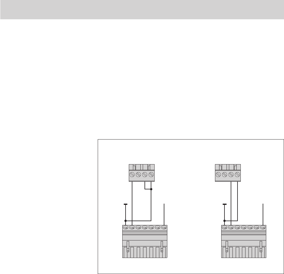
Fig. 10: Connecting the OTT RLS
to LogoSens 2 or DuoSens using
an SDI-12 interface.
The letters above the screw terminal strip
identify the possible connections on the
LogoSens 2/DuoSens.
SDI-12
Input
A … R
4
31 2
LogoSens 2
SDI-12
Input
A
4
31 2
DuoSens
RLS
542 3176
RLS
542 3176
+9.6 … 28 V
+9.6 … 28 V
25
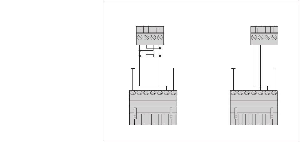
Method B: Connect OTT RLS using the physical RS-485 interface (SDI-12 protocol
via physical RS-485 interface). Refer to Chapter 5.3 for the maximum connecting
cable length and the recommended wire cross-section:
Connect the OTT RLS to the LogoSens 2 Station Manager or to the DuoSens
Compact Datalogger as shown in Figure 11. Take note of the operating
instruct ions for the LogoSens 2/DuoSens.
Fig. 11: Connecting the OTT RLS to Logo-
Sens 2 or DuoSens using an RS-485 inter-
face (SDI-12 protocol).
The letters above the screw terminal
strip identify the possible connections
on the LogoSens 2/DuoSens.
When connecting the OTT RLS to the
LogoSens 2, use a 120 Ohm terminator
(order number: 96.300.205.9.5).
120 Ohm
terminator
RS-485
Input RS-485
Input
RLS RLS
5
42 3176542 3176
+9.6 … 28 V
+9.6 … 28 V
A … R
431 2
LogoSens 2
A
431 2
DuoSens
26
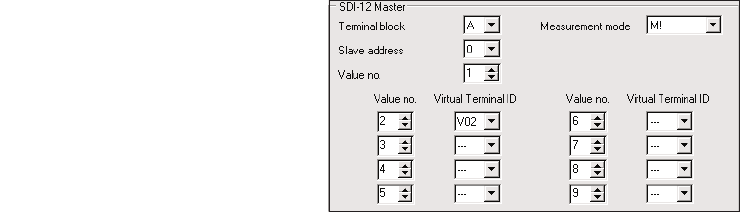
Configuring the LogoSens 2/DuoSens for the OTT RLS with SDI-12
interface
Create a LogoSens 2/DuoSens channel with SDI-12 Master or OTT SDI RS485
function block (serial sensors tab).
Apply the following settings:
Terminal block LogoSens 2: A … R
DuoSens SDI-12 Master: A 3-4 (specified)
DuoSens OTT SDI RS485: A 1-2 (specified)
terminal block used (screw terminal strip) of the
LogoSens 2/DuoSens.
Slave address SDI-12 bus address. Each address may only be
allocated once to an SDI-12 bus feed!
(Checking/setting: see operating instructions
LogoSens 2/ DuoSens, Chapter SDI-12 transparent
mode; alternatively with OTT USB/SDI-12 inter-
face)
Factory setting of the OTT RLS: 0
Value no. 1
Identifies which value from the OTT RLS is recorded
in this channel. (The OTT RLS determines two values
with the command aM!: measurement and status
information.)
Measurement mode M! (SDI-12 measurement command for this channel)
Allocation of the status information to a virtual
terminal.
In the relevant Channel function blocks, adjust the required units and number of
digits after the decimal place (m: 3; cm: 0; ft: 2; status information: 0).
Note:
To record the measurements and status information of an OTT RLS, two channels
in the LogoSens 2/DuoSens are thus necessary. The first channel contains the
function block SDI-12 Master or OTT SDI RS485 as the input signal. The second
channel contains a function block Virtual Sensor (V02) as the input signal. If
the recording of status information is not required, no entry is necessary in the
Value no./Virtual terminal ID field.
The measuring mode M1! supplies extended status information. If required, this
can also be recorded in an additional channel with function block SDI-12 Master/
OTT SDI RS485.
You will find further information on the used SDI-12 commands and responses
in Chapter 6, SDI-12 commands and responses.
Please note: The OTT PLS makes the measurement results available a maximum
of 25 seconds after the SDI-12 command aM!!
Fig. 12: Adjusting the operating parameters
of the LogoSens 2/DuoSens
SDI-12 Master function block.
The function block OTT SDI RS485
is set in the same way.
Value no./
Virtual terminal ID
27
Annex B – Connecting the OTT RLS to LogoSens 2 or DuoSens using a
4 … 20 mA interface
Connect the OTT RLS to the LogoSens 2 Station Manager or to the DuoSens
Compact Datalogger as shown in Figure 13 and 14. Take note of the operating
instructions for the LogoSens 2/DuoSens. Maximum connecting cable length/
recommended wire cross-section: depending on the amount of voltage supply
and the size of the burden (load resistor). Please note that the ohmic resistance
of the connecting cable together with the eventually existing burden do not
exceed the max. allowed load resistance (see Chapter 5.7)!
4 … 20 mA
Input
C … F*
431 2
542 3176
DuoSens
RLS
* only with a DuoSens
with analog extension
+9.6 … 28 V
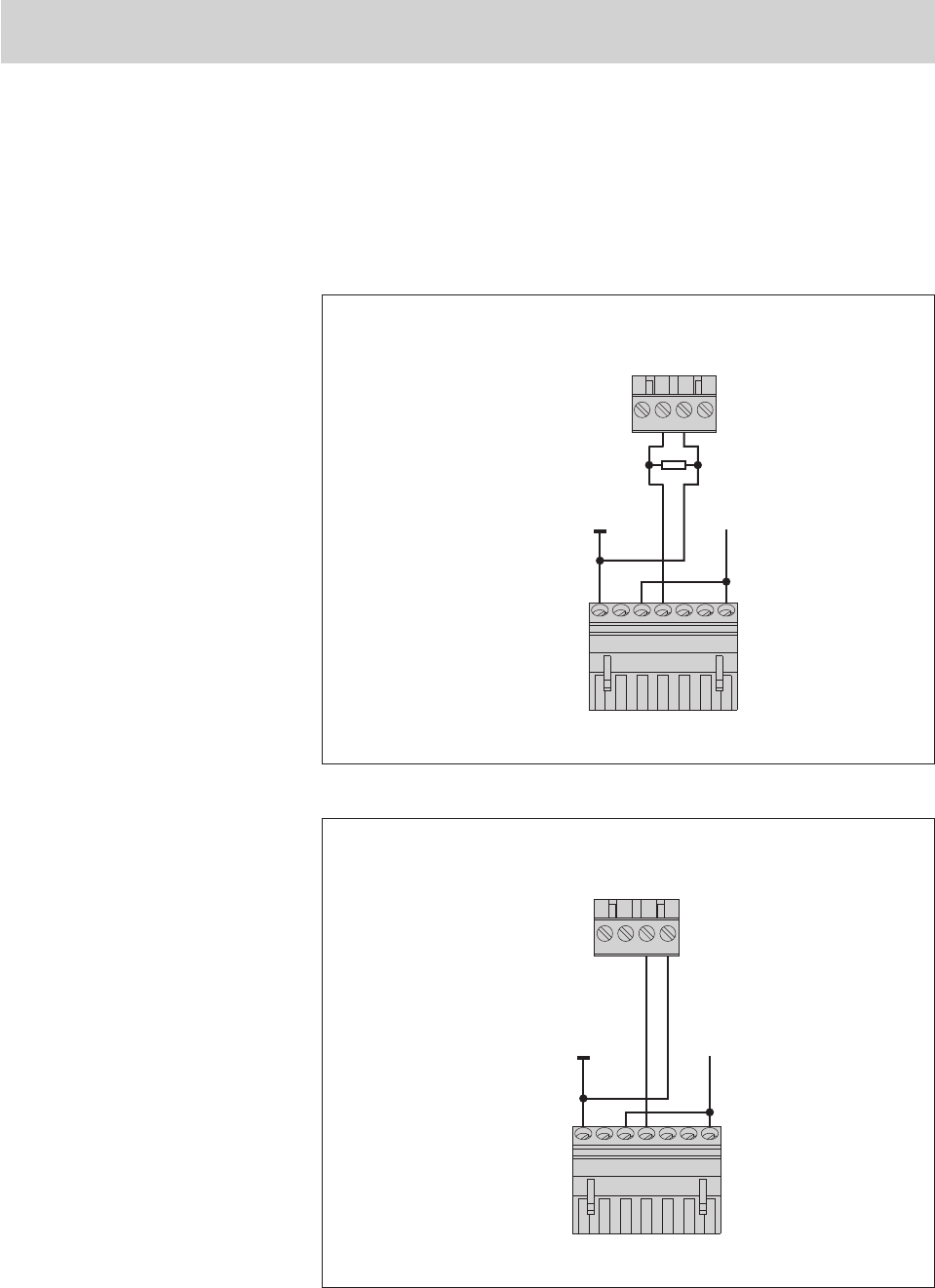
Fig. 14: Connecting the OTT RLS to
DuoSens using a 4 … 20 mA interface.
The letters above the screw terminal
strip identify the possible connections
on the DuoSens.
4 … 20 mA Input
A … R
431 2
LogoSens 2
RLS
542 3176
100 Ohm load resistor
+9,6 … 28 V
Fig. 13: Connecting the OTT RLS to
LogoSens 2 using a 4 … 20 mA interface
Use the 100 Ohm OTT resistor
(order number: 55.550.800.9.5).
The letters above the screw terminal
strip identify the possible connections
on the LogoSens 2.
28
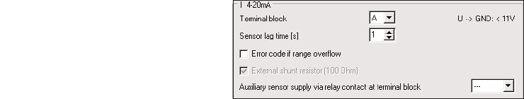
Configuring the LogoSens 2/DuoSens for OTT RLS with 4 … 20 mA
interface
Create a LogoSens 2/DuoSens channel with function block I 4-20 mA
(LogoSens 2) or U/I/Pt100/… (DuoSens) (Analog sensors tab).
Apply the following settings:
Terminal block LogoSens 2: A … R
DuoSens: C … F
terminal block used (screw terminal strip)
of the LogoSens 2/DuoSens.
Set to I 4-20 mA ext.
Sensor lag time (s) switches on the LogoSens 2/DuoSens input
1 second before the actual measurement
process
if required: record error codes on range
overflow
not required with an OTT RLS
Insert a 2-point scaling function block into this channel and adjust the relating
distance values for the outputed current values (e. g. Point 1: 4 ➝0; Point 2:
20 ➝35 m · 115 ft). This function also enables the referencing to a level zero.
In the Channel function block, set the unit and number of digits after the decimal
place (m: 3; cm: 0; ft: 2)..
Auxiliary sensor supply via
relay contact at terminal block
(only for LogoSens 2)
□Error code if range overflow
Measurement mode
(only with DuoSens)
Fig. 15: Setting operating parameters of the
LogoSens 2 I 4-20 mA function block.
The DuoSens function block U/I/Pt100/…
is set in the same way.
29
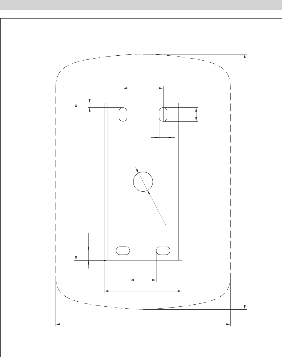
Annex C – Dimensions of wall bracket/position of fixing bores
35 mm · 1.38"
137 mm · 5.39"
67.5 mm · 2.66"
152 mm · 5.98"
12 mm
0.47"
4 0.16"
7
0.28"
8.5 0.33"
23 mm
0.91"
222 mm · 8.74"
Ø
17 mm · 0.67"
30

Annex D – Declaration of Conformity
31

Annex E – Radio Approval USA: Grant of Equipment Authorization
32
OTT Hydromet GmbH
Ludwigstrasse 16
87437 Kempten · Germany
Phone +49 831 5617-0
Fax +49 831 5617-209
info@ott.com · www.ott.com
Document number
63.107.001.B.E 01-0714