OvisLink AIRMAX5 802.11a 108Mbps Outdoor Wireless CPE User Manual AirLive AirMax5
OvisLink Corp. 802.11a 108Mbps Outdoor Wireless CPE AirLive AirMax5
UserManual.wiki
>
OvisLink
>
AIRMAX5 User Manual
>
User Manual I
Contents
1.
User Manual I
2.
User Manual II
User Manual I
Navigation menu
Upload a User Manual
Namespaces
Wiki Guide
HTML
PDF
Info
Views
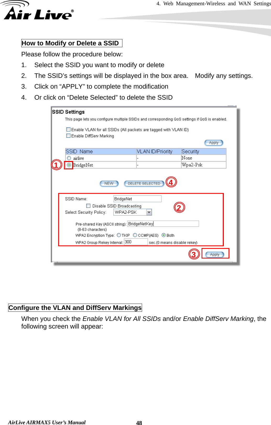
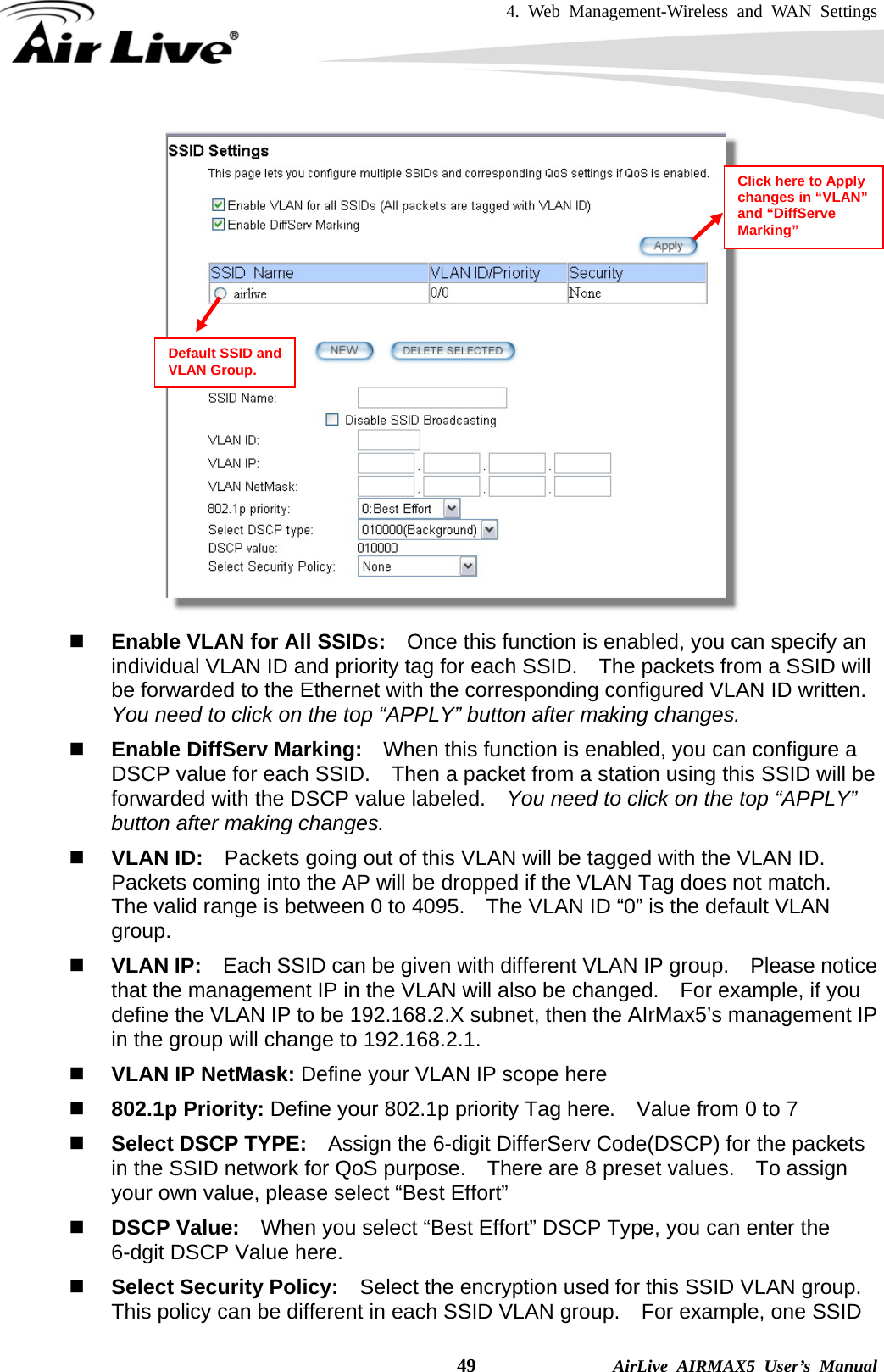
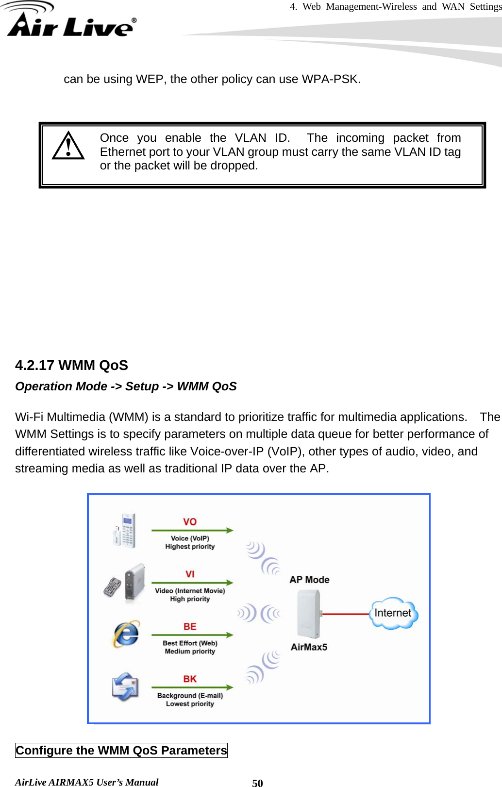
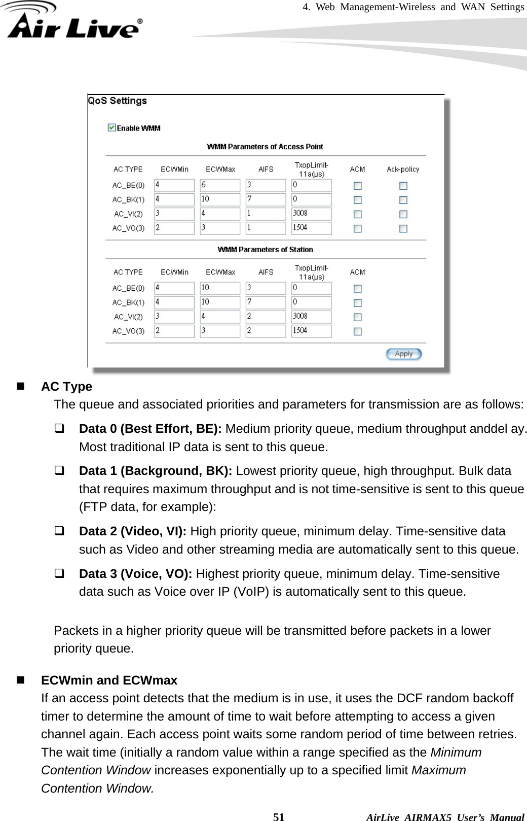
User Manual
Discussion / Help
Navigation