OvisLink AIRMAX5 802.11a 108Mbps Outdoor Wireless CPE User Manual AirLive AirMax5
OvisLink Corp. 802.11a 108Mbps Outdoor Wireless CPE AirLive AirMax5
UserManual.wiki
>
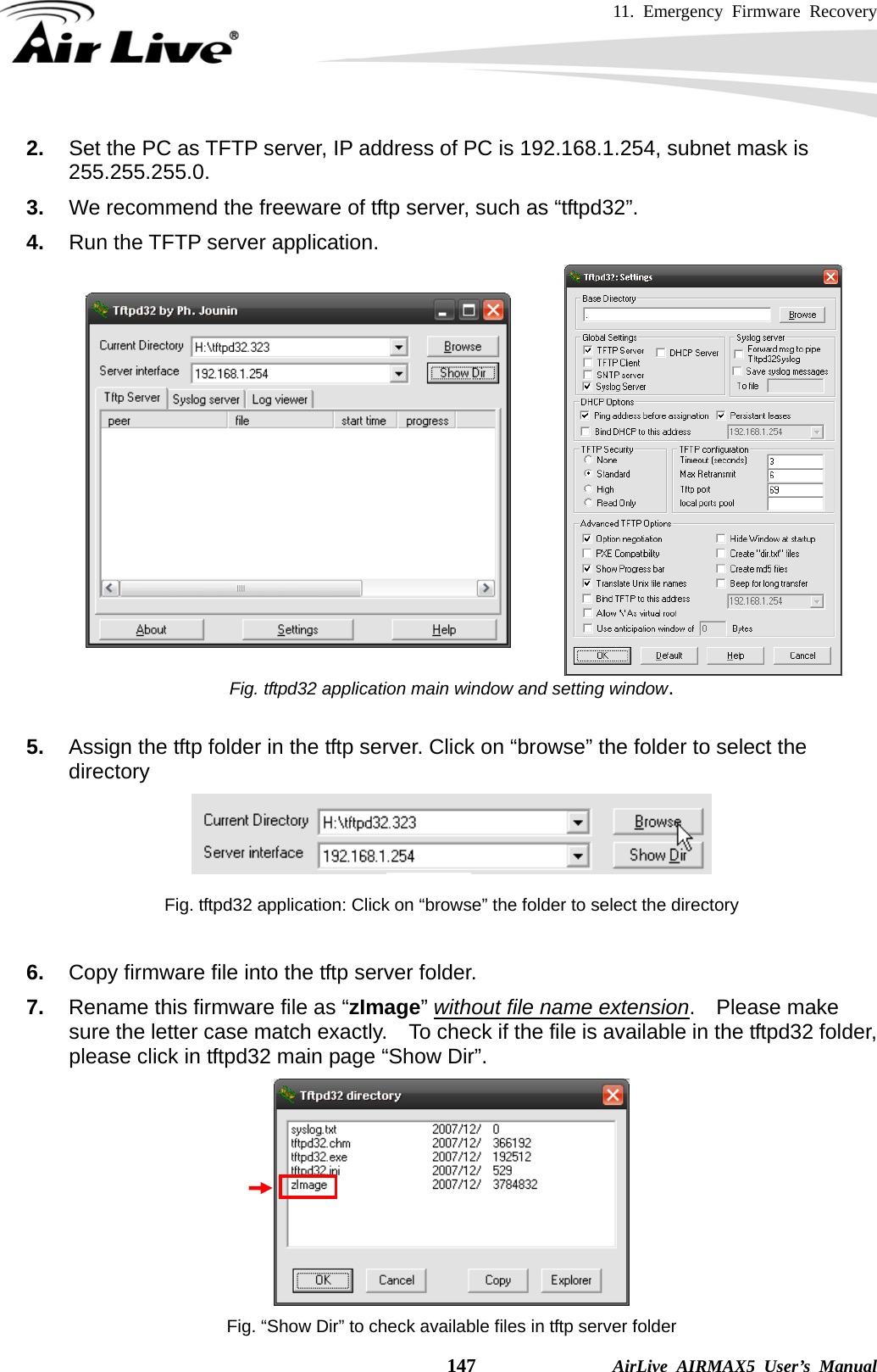
OvisLink
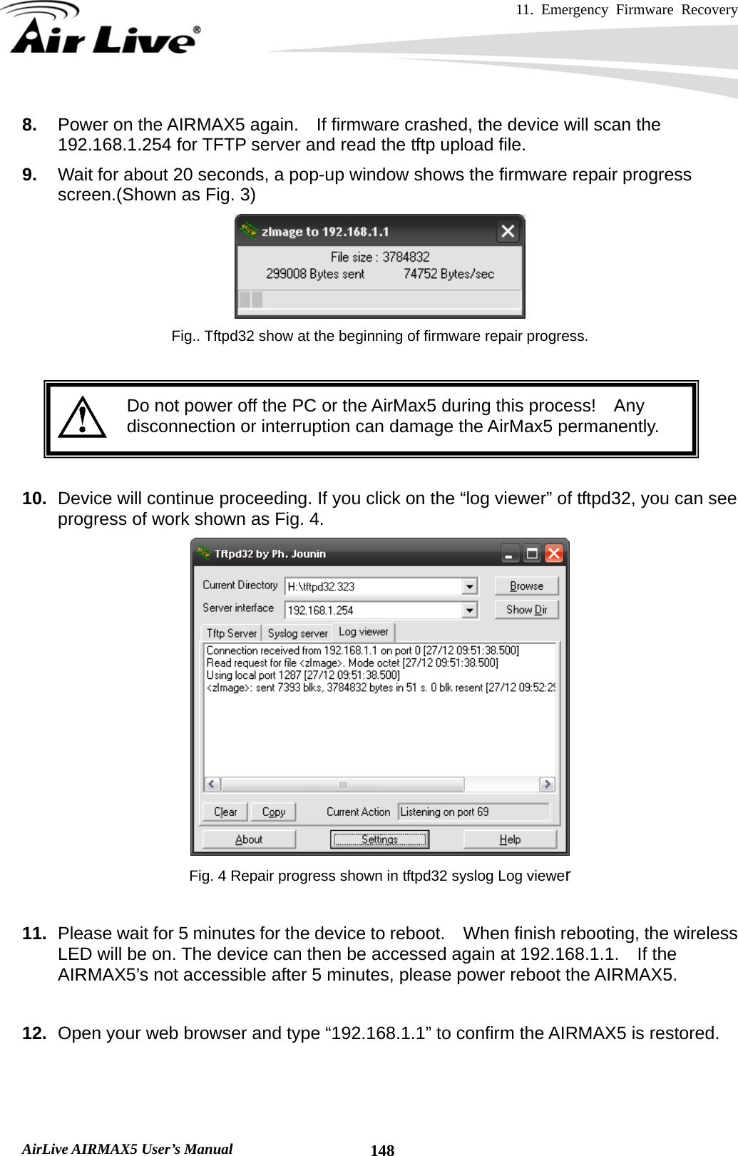
>
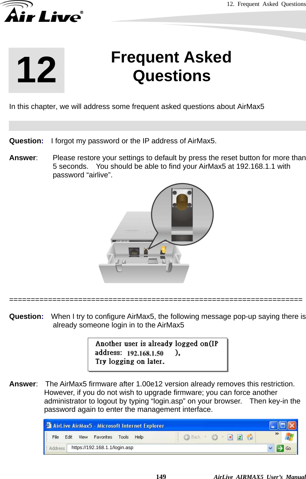
AIRMAX5 User Manual
>
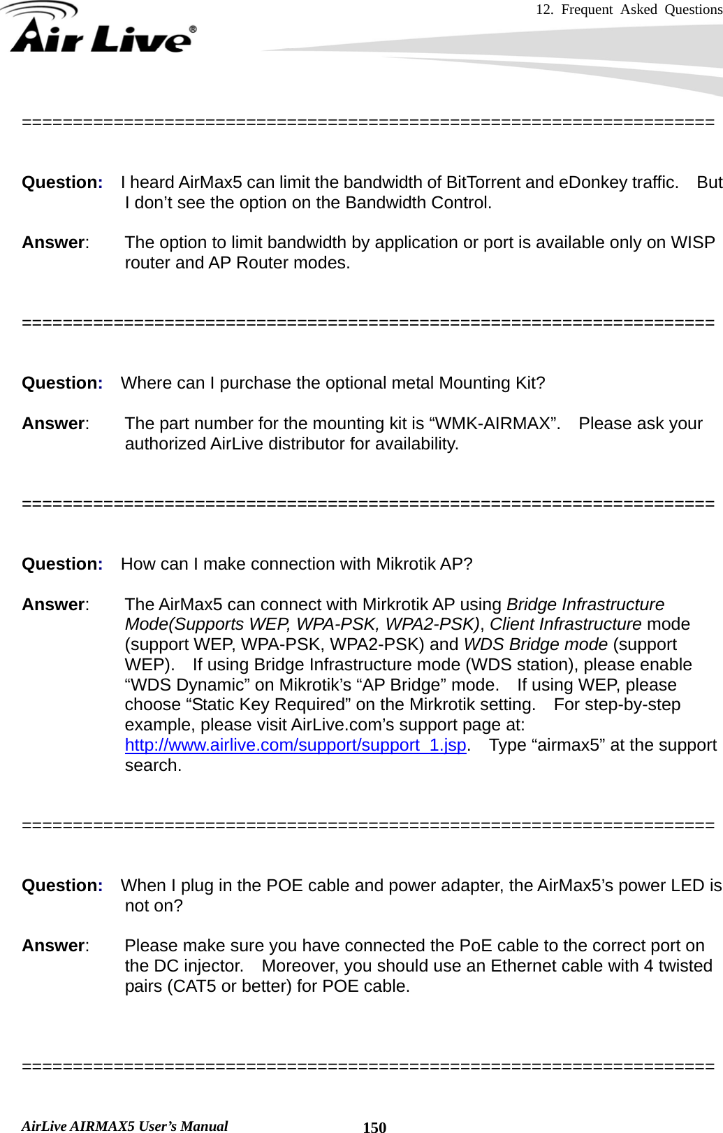
User Manual II
Contents
1.
User Manual I
2.
User Manual II
User Manual II
Navigation menu
Upload a User Manual
Namespaces
Wiki Guide
HTML
PDF
Info
Views
User Manual
Discussion / Help
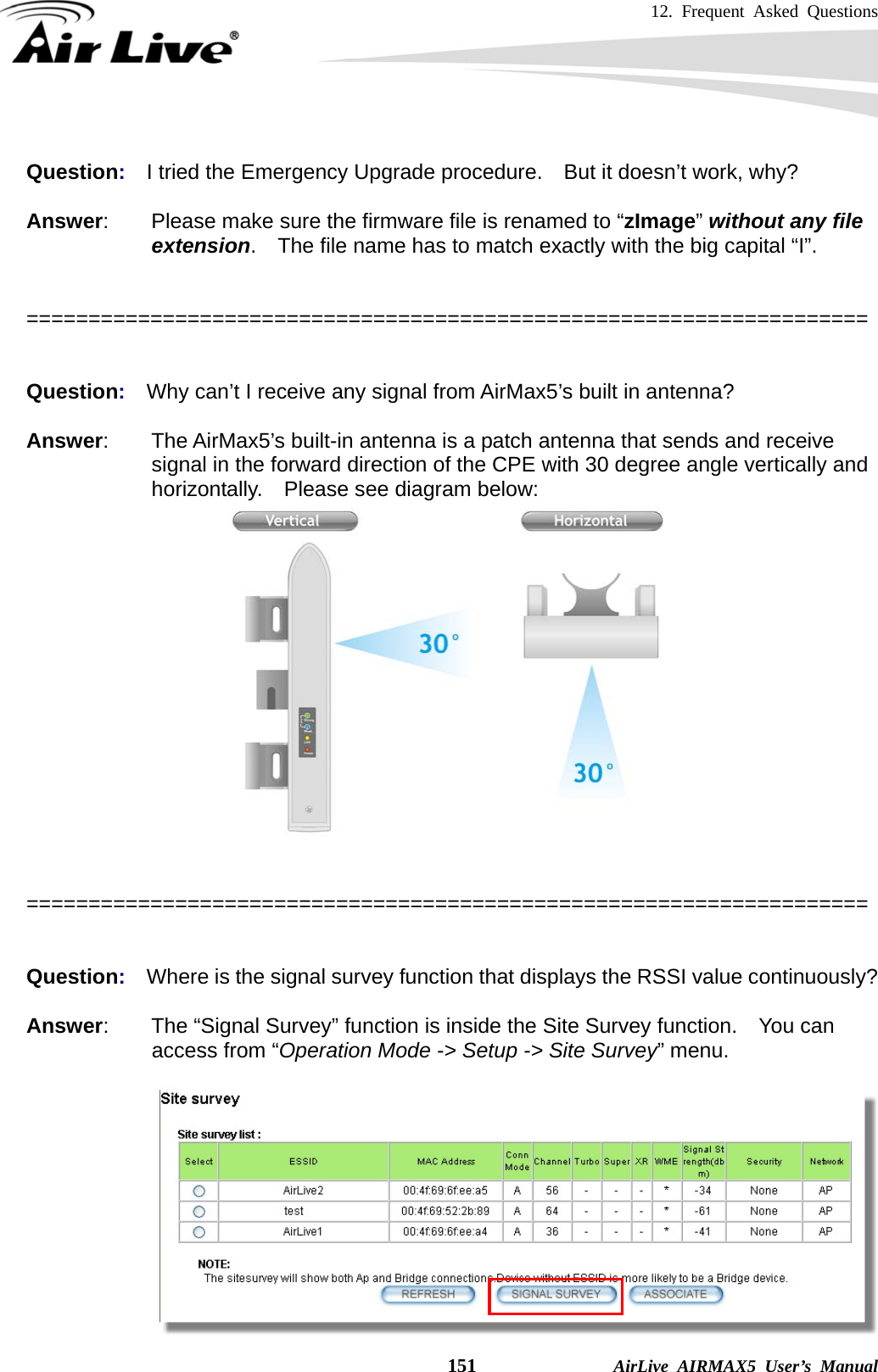
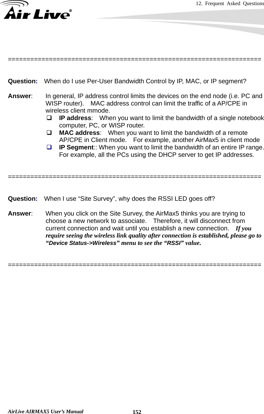
Navigation
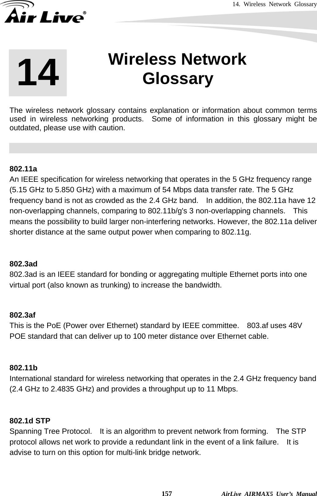
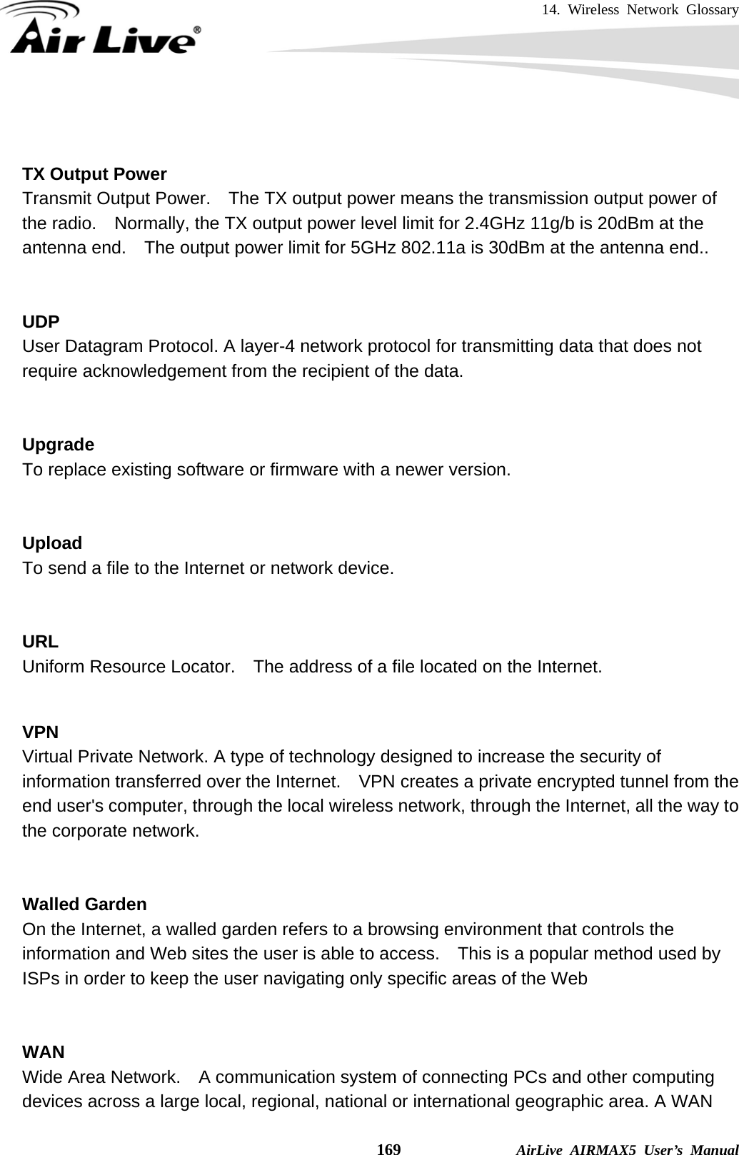
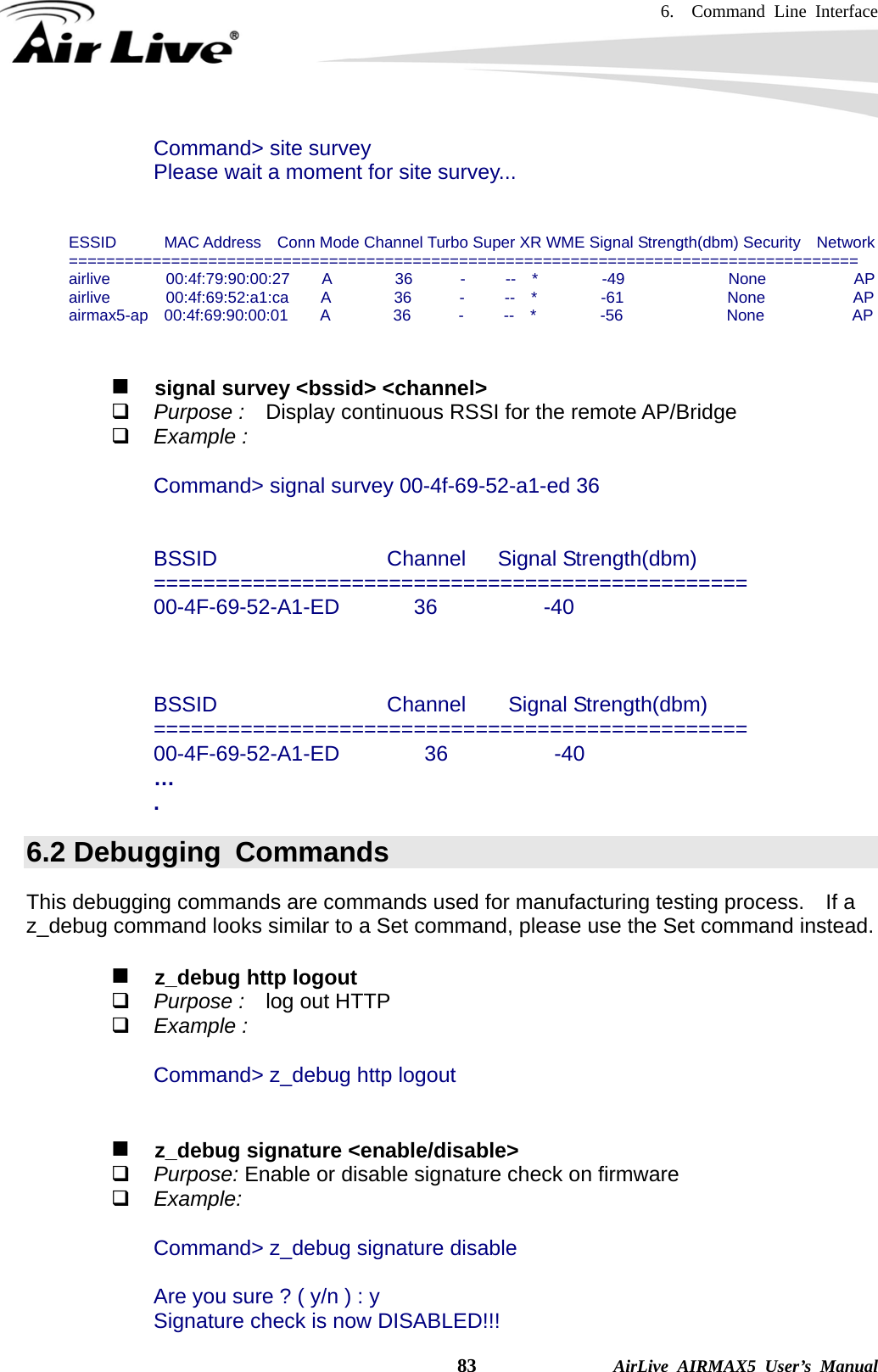
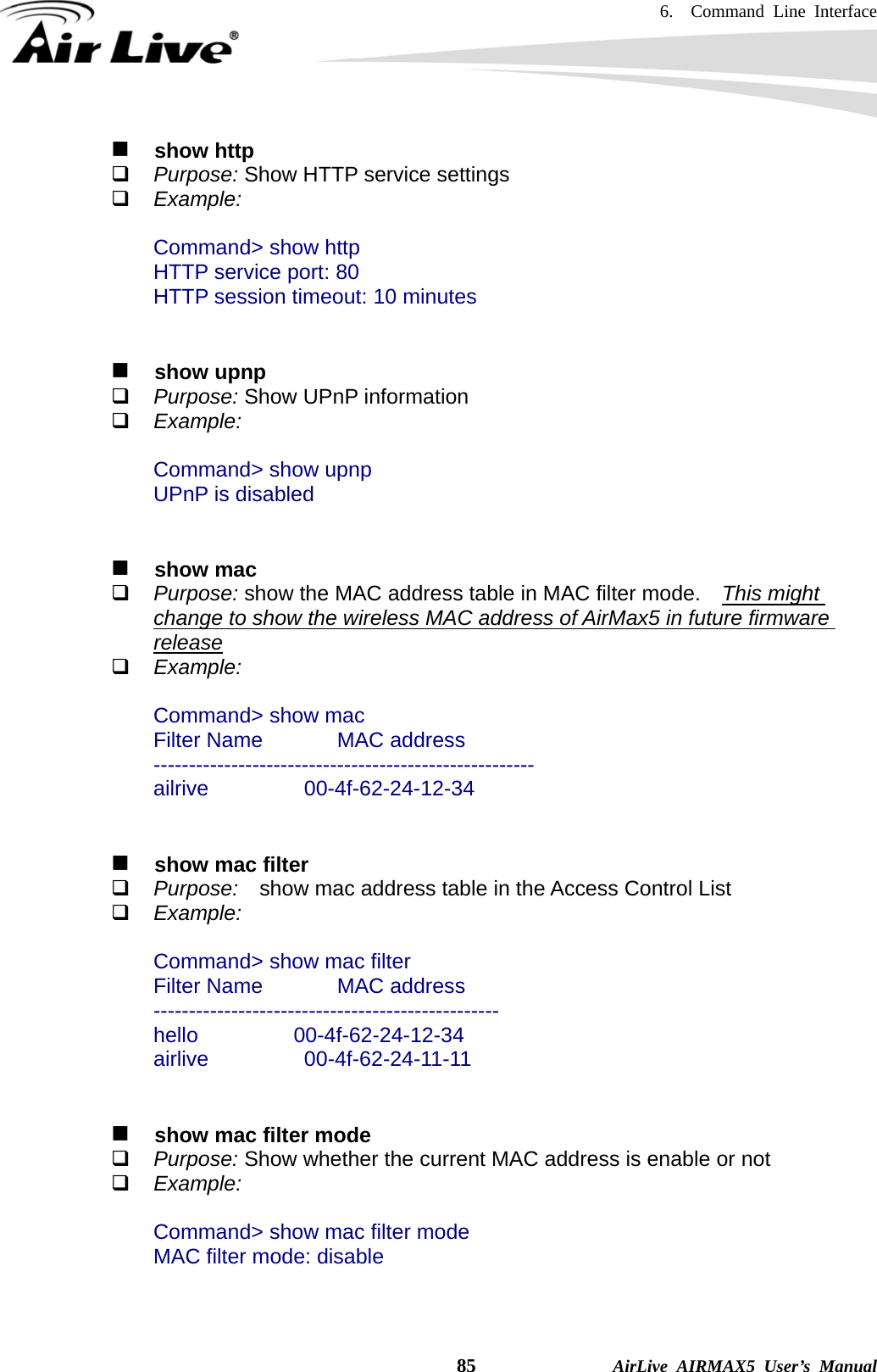
![6. Command Line Interface AirLive AIRMAX5 User’s Manual 82 change password Purpose: Change login password Example: Command> change password 123 password is set to: 123 ftptest <ssid> 11a <channel> Purpose: Test if a SSID’s connection is okay Example: Command> ftptest airlive 11a 40 Set SSID : airlive , mode = 11a , channel = 40 ok ! save config Purpose: save configuration file. Please remember to “save config” after making changes Example: Command> save config None clear config Purpose: Clear configuration to default Example: Command> clear config Are you sure ? ( y/n ) : y Write flash block [/dev/mtd3] Write file is [/etc/defsysconfig.conf] Rebooting... webservice <lan | wan> <enable | disable> Purpose: Enable or Disable Web management interface on LAN or WAN Example: Command> webservice lan enable webservice from lan enable site survey Purpose: Site Survey display Example:](https://usermanual.wiki/OvisLink/AIRMAX5.User-Manual-II/User-Guide-1156956-Page-2.png)
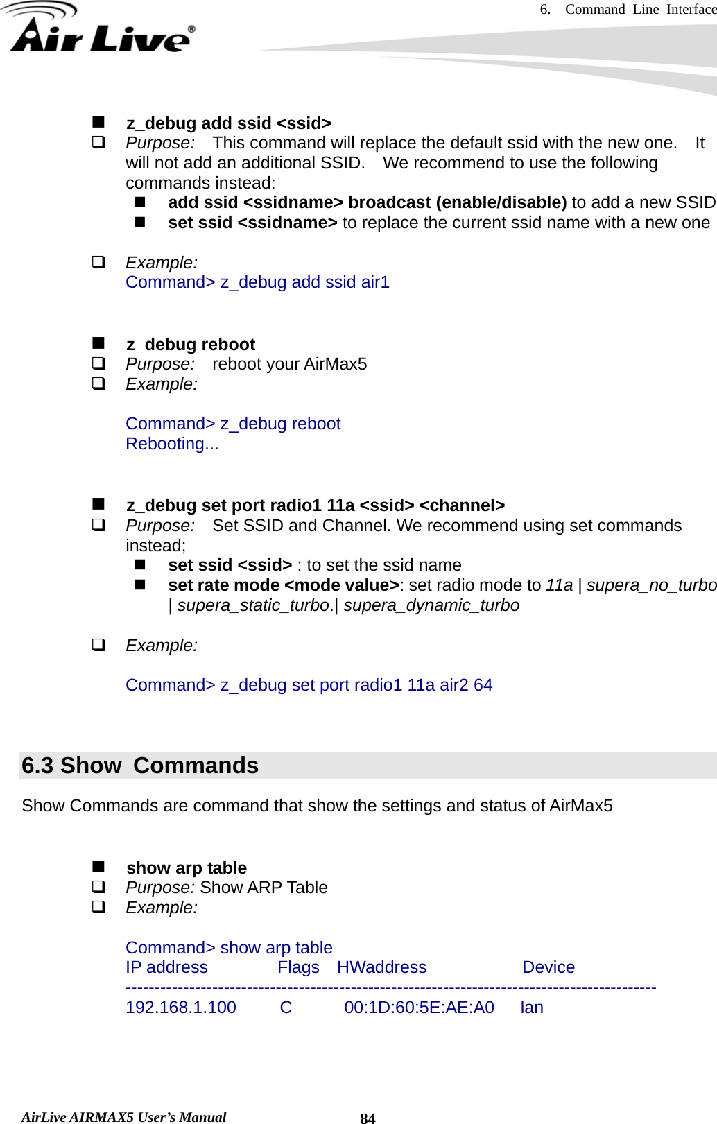
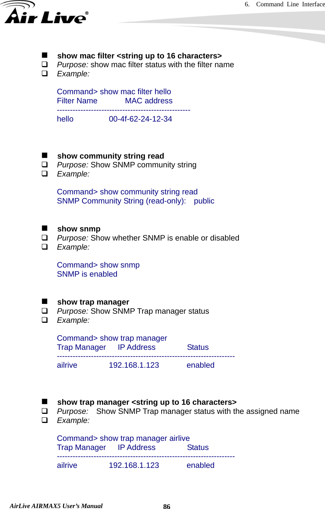
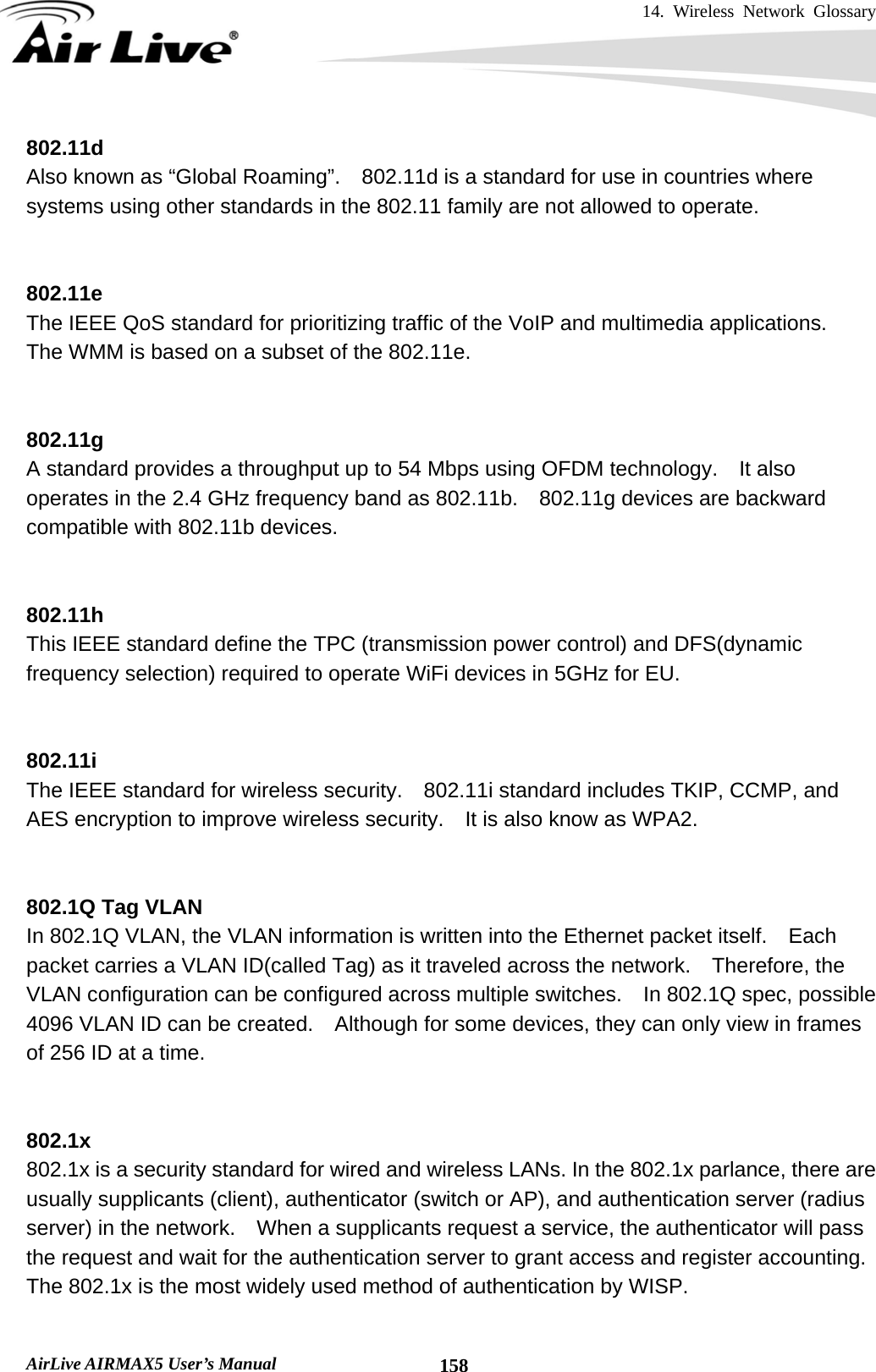
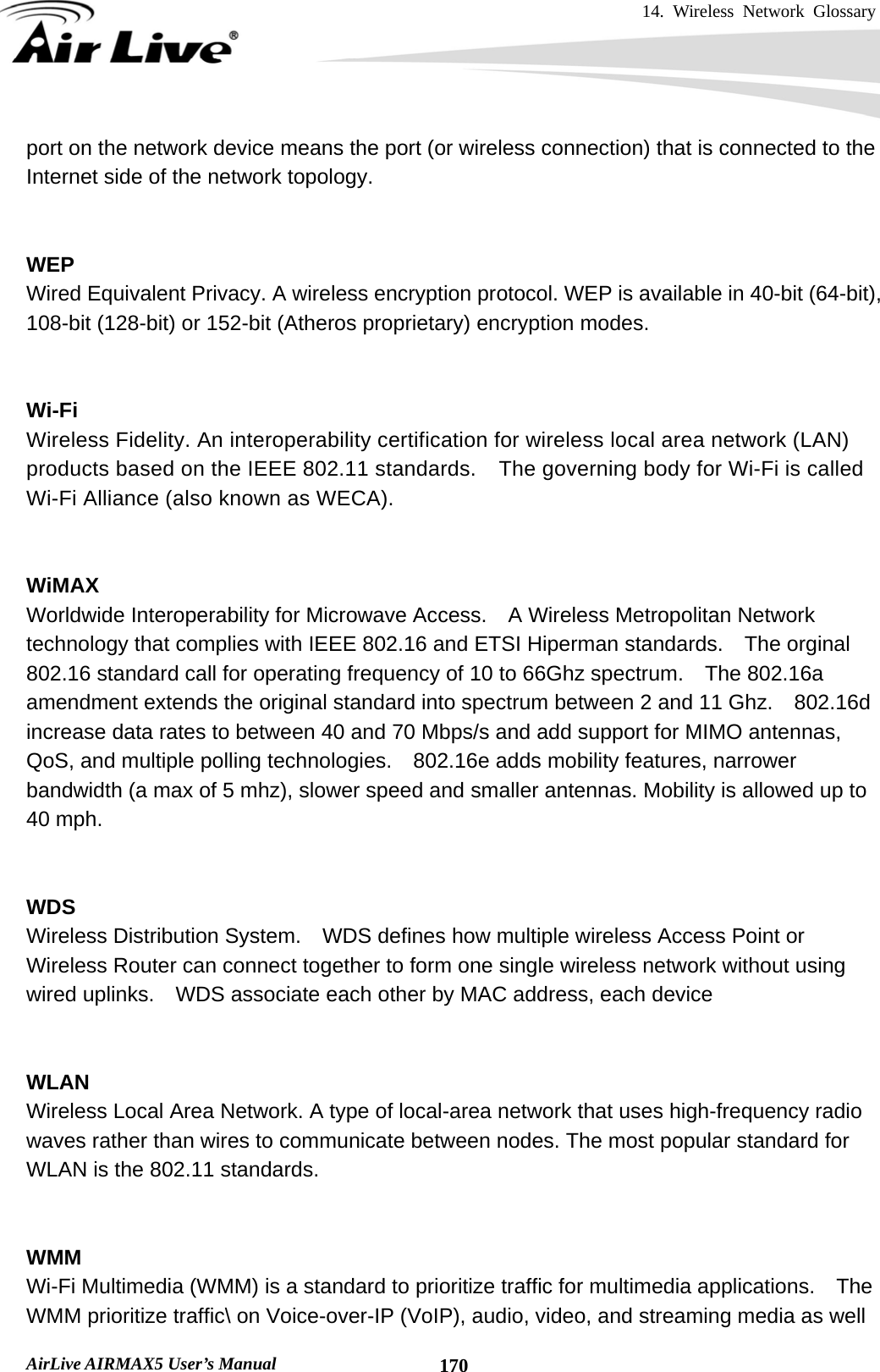
![6. Command Line Interface 89 AirLive AIRMAX5 User’s Manual show mode Purpose: Show what operation is AirMax currently set to Example: Command> show mode operation mode: access point show wireless setting Purpose: Show wireless settings Example: Command> show wireless setting Radio[1] operation mode: access point ssid name : air2 wireless state : enable ssid broadcast : enable radio[1] mode : 11a radio[1] channel : 64 show wireless security Purpose: Show current wireless security policy Example: Command> show wireless security Radio1 security policy: none show <wan | lan> settings Purpose: Show LAN or WAN port IP settings Example: Command> show lan settings Lan ip type : static Lan ip address : 192.168.1.1 Lan ip netmask : 255.255.255.0 Lan ip gateway : 192.168.1.254 Lan ip dnsserv : 0.0.0.0 show firmware version show vlan ssid list show wds settings show advanced wireless show syslogd](https://usermanual.wiki/OvisLink/AIRMAX5.User-Manual-II/User-Guide-1156956-Page-9.png)