OvisLink AIRMAX5 802.11a 108Mbps Outdoor Wireless CPE User Manual AirLive AirMax5
OvisLink Corp. 802.11a 108Mbps Outdoor Wireless CPE AirLive AirMax5
OvisLink >
Contents
- 1. User Manual I
- 2. User Manual II
User Manual II
6. Command Line Interface
81 AirLive AIRMAX5 User’s Manual
In this chapter, we will explain commands that are available through Telnet or SSH
interface. We will provide descriptions for the commands, example settings and the
AirMax5’s response. The purpose for this chapter is to introduce available CLI commands
only. For detail descriptions on the concept and application of the settings, please refer to
chapter 4 and chapter 5.
Before reading this chapter, please go through Section 3.3 of Chapter 3. It contains
information on how to login Telnet or SSH/SSH2 interface. For quick reference, the login
and password is as bellowed:
Telnet
Password: airlive
SSH/SSH2
First login
z Login: root
z Password: <nothing, just press enter>
Second login:
z Password: airlive
When you change AirMax5’s password, it will change the second login’s password
only.
You can get a list of available commands by typing “help” at the command prompt.
You must remember to save the configurations by typing “save
config” at the command prompt after making changes, otherwise, the
configuration will be lost after reboot.
6.1 System Commands
ping <IP address>
Purpose: to ping a remote IP address
Example:
Command> ping 192.168.1.1
PING 192.168.1.1 (192.168.1.1): 56 data bytes
64 bytes from 192.168.1.1: icmp_seq=0 ttl=64 time=1.8 ms
64 bytes from 192.168.1.1: icmp_seq=1 ttl=64 time=1.0 ms
6
6
. Command Line Interface
This is the command
Here explains the usage
of the command
Example
command and
response

6. Command Line Interface
AirLive AIRMAX5 User’s Manual 82
change password
Purpose: Change login password
Example:
Command> change password 123
password is set to: 123
ftptest <ssid> 11a <channel>
Purpose: Test if a SSID’s connection is okay
Example:
Command> ftptest airlive 11a 40
Set SSID : airlive , mode = 11a , channel = 40 ok !
save config
Purpose: save configuration file. Please remember to “save config” after
making changes
Example:
Command> save config
None
clear config
Purpose: Clear configuration to default
Example:
Command> clear config
Are you sure ? ( y/n ) : y
Write flash block [/dev/mtd3]
Write file is [/etc/defsysconfig.conf]
Rebooting...
webservice <lan | wan> <enable | disable>
Purpose: Enable or Disable Web management interface on LAN or WAN
Example:
Command> webservice lan enable
webservice from lan enable
site survey
Purpose: Site Survey display
Example:

6. Command Line Interface
83 AirLive AIRMAX5 User’s Manual
Command> site survey
Please wait a moment for site survey...
ESSID MAC Address Conn Mode Channel Turbo Super XR WME Signal Strength(dbm) Security Network
=====================================================================================
airlive 00:4f:79:90:00:27 A 36 - -- * -49 None AP
airlive 00:4f:69:52:a1:ca A 36 - -- * -61 None AP
airmax5-ap 00:4f:69:90:00:01 A 36 - -- * -56 None AP
signal survey <bssid> <channel>
Purpose : Display continuous RSSI for the remote AP/Bridge
Example :
Command> signal survey 00-4f-69-52-a1-ed 36
BSSID Channel Signal Strength(dbm)
================================================
00-4F-69-52-A1-ED 36 -40
BSSID Channel Signal Strength(dbm)
================================================
00-4F-69-52-A1-ED 36 -40
…
.
6.2 Debugging Commands
This debugging commands are commands used for manufacturing testing process. If a
z_debug command looks similar to a Set command, please use the Set command instead.
z_debug http logout
Purpose : log out HTTP
Example :
Command> z_debug http logout
z_debug signature <enable/disable>
Purpose: Enable or disable signature check on firmware
Example:
Command> z_debug signature disable
Are you sure ? ( y/n ) : y
Signature check is now DISABLED!!!

6. Command Line Interface
AirLive AIRMAX5 User’s Manual 84
z_debug add ssid <ssid>
Purpose: This command will replace the default ssid with the new one. It
will not add an additional SSID. We recommend to use the following
commands instead:
add ssid <ssidname> broadcast (enable/disable) to add a new SSID
set ssid <ssidname> to replace the current ssid name with a new one
Example:
Command> z_debug add ssid air1
z_debug reboot
Purpose: reboot your AirMax5
Example:
Command> z_debug reboot
Rebooting...
z_debug set port radio1 11a <ssid> <channel>
Purpose: Set SSID and Channel. We recommend using set commands
instead;
set ssid <ssid> : to set the ssid name
set rate mode <mode value>: set radio mode to 11a | supera_no_turbo
| supera_static_turbo.| supera_dynamic_turbo
Example:
Command> z_debug set port radio1 11a air2 64
6.3 Show Commands
Show Commands are command that show the settings and status of AirMax5
show arp table
Purpose: Show ARP Table
Example:
Command> show arp table
IP address Flags HWaddress Device
--------------------------------------------------------------------------------------------
192.168.1.100 C 00:1D:60:5E:AE:A0 lan

6. Command Line Interface
85 AirLive AIRMAX5 User’s Manual
show http
Purpose: Show HTTP service settings
Example:
Command> show http
HTTP service port: 80
HTTP session timeout: 10 minutes
show upnp
Purpose: Show UPnP information
Example:
Command> show upnp
UPnP is disabled
show mac
Purpose: show the MAC address table in MAC filter mode. This might
change to show the wireless MAC address of AirMax5 in future firmware
release
Example:
Command> show mac
Filter Name MAC address
------------------------------------------------------
ailrive 00-4f-62-24-12-34
show mac filter
Purpose: show mac address table in the Access Control List
Example:
Command> show mac filter
Filter Name MAC address
-------------------------------------------------
hello 00-4f-62-24-12-34
airlive 00-4f-62-24-11-11
show mac filter mode
Purpose: Show whether the current MAC address is enable or not
Example:
Command> show mac filter mode
MAC filter mode: disable

6. Command Line Interface
AirLive AIRMAX5 User’s Manual 86
show mac filter <string up to 16 characters>
Purpose: show mac filter status with the filter name
Example:
Command> show mac filter hello
Filter Name MAC address
---------------------------------------------------
hello 00-4f-62-24-12-34
show community string read
Purpose: Show SNMP community string
Example:
Command> show community string read
SNMP Community String (read-only): public
show snmp
Purpose: Show whether SNMP is enable or disabled
Example:
Command> show snmp
SNMP is enabled
show trap manager
Purpose: Show SNMP Trap manager status
Example:
Command> show trap manager
Trap Manager IP Address Status
--------------------------------------------------------------------
ailrive 192.168.1.123 enabled
show trap manager <string up to 16 characters>
Purpose: Show SNMP Trap manager status with the assigned name
Example:
Command> show trap manager airlive
Trap Manager IP Address Status
--------------------------------------------------------------------
ailrive 192.168.1.123 enabled

6. Command Line Interface
87 AirLive AIRMAX5 User’s Manual
show radius server
Purpose: Show radius server settings
Example:
Command> show radius server
RADIUS Server State IP/Port
----------------------------------------------------------------------------------------
Primary Disabled 0.0.0.0/1812
Secondary Disabled 0.0.0.0/1812
RADIUS Server reattempt: 60 seconds
show radius server <primary | secondary>
Purpose: Show settings of primary or secondary radius server
Example:
Command> show radius server primary
RADIUS Server: primary
State: Disabled
Server IP: 0.0.0.0
Port Number: 1812
Shared Secret:
show log level
Purpose: show log level
Example:
Command> show log level
Log level is 8
show telnet / system
Purpose: show telnet management information and system status
Example:
Command> show telnet
Telnet session timeout: 0 minutes
Telnet port number: 23
Telnet state: enable
Command> show system
System Name: AirMax5
------------------------------------------------------------------------------
S/W Version: 1.00e09a

6. Command Line Interface
AirLive AIRMAX5 User’s Manual 88
H/W Version: S0A
System LAN MAC: 00-4F-79-90-00-16
Wireless MAC: 00-4F-79-90-00-15
WMAC-0: 00-4F-79-90-00-15
show snmp statistics
Purpose: Show SNMP satistics
Example:
Command> show snmp statistics
Timeout: No Response from 192.168.1.1
Received Transmitted
----------------------------------------------------------------------------
Total Packets 1 1
Request Variables 11
SET Variables 0
GET Requests 0
GETNEXT Requests 15
GET-RESPONSEs 0 25
SET Requests 0
Errors:
Bad Versions 0
Bad Community Uses: 0
ASN1 Parse Errors 0
Packet Too Long 0
NO-SUCH-NAME Errors 0
BAD-VALUE Errors 0
READ-ONLY Errors 0
GENERAL-ERR Errors 0
show rssi
Purpose: Show RSSI signal strength
Example:
Command> show rssi
Please wait a moment for site survey...
ESSID MAC Address Signal Strength(dbm)
=======================================================
airlive 0:4f:69:52:a1:ca -59
airmax5-ap 00:4f:69:90:00:01 -47

6. Command Line Interface
89 AirLive AIRMAX5 User’s Manual
show mode
Purpose: Show what operation is AirMax currently set to
Example:
Command> show mode
operation mode: access point
show wireless setting
Purpose: Show wireless settings
Example:
Command> show wireless setting
Radio[1] operation mode: access point
ssid name : air2
wireless state : enable
ssid broadcast : enable
radio[1] mode : 11a
radio[1] channel : 64
show wireless security
Purpose: Show current wireless security policy
Example:
Command> show wireless security
Radio1 security policy: none
show <wan | lan> settings
Purpose: Show LAN or WAN port IP settings
Example:
Command> show lan settings
Lan ip type : static
Lan ip address : 192.168.1.1
Lan ip netmask : 255.255.255.0
Lan ip gateway : 192.168.1.254
Lan ip dnsserv : 0.0.0.0
show firmware version
show vlan ssid list
show wds settings
show advanced wireless
show syslogd

6. Command Line Interface
AirLive AIRMAX5 User’s Manual 90
show antenna
Purpose: Check antenna polarization
Example:
Command> show antenna
Antenna setting is Vertical;
show ratemode
Purpose: Show whether the AirMax is using 5MHz, 10MHz, or 20MHz
channel width
Example:
Command> show ratemode
Ratemode is Full(20Mhz);
show noise immunity
Purpose: Show the noise immunity setting
Example:
Command> show noise immunity
Noise immunity is enable
6.4 Set Commands
The Set Commands are to make changes to the AirMax5’s settings
set http timeout <timeout value in minutes, 1-999>
Purpose: Set the timeout value for HTTP management
Example:
Command> set http timeout 10
HTTP timeout: 10 minutes
set system <contact |location> <string up to 60 characters>
Purpose: Set the system’s location and contact info
Example:
Command> set system location 60
System Location: 60

6. Command Line Interface
91 AirLive AIRMAX5 User’s Manual
set system name <string up to 32 characters>
Purpose: Set system’s name
Example:
Command> set system name airlive
System Name: airlive
set mac filter mode <MAC filter mode, disabled/grant/deny>
Purpose: Set MAC filter mode or disable MAC filtering.
Example:
Command> set mac filter mode disabled
mac filter mode is set to disabled
set community string <read |write> <string up to 32 characters>
Purpose: Set SNMP community string
Example:
Command> set community string write test
community string for write: test
Command> set community string read test
community string for read: test
set radius server reattempt <reattempt interval in minutes, now no limit
in seconds>
Purpose: set radius server reattempt interval in minutes
Example:
Command> set radius server reattempt 20
/etc/wlan/ap_service: 17: uname: not found
killall: wpa_supplicant: no process killed
/etc/wlan/ap_service: 17: uname: not found
Using /lib/modules/2.4.25-LSDK-5.1.0.42/wlan/ath_hal.o
Using /lib/modules/2.4.25-LSDK-5.1.0.42/wlan/ath_rate_atheros.o
Using /lib/modules/2.4.25-LSDK-5.1.0.42/wlan/ath_dfs.o
Using /lib/modules/2.4.25-LSDK-5.1.0.42/wlan/ath_ahb.o
<mapping sub-ioctl turbo to cmd 0x8BE0-1>
<mapping sub-ioctl set_installmode to cmd 0x8BE0-75>
<mapping sub-ioctl set_threslower to cmd 0x8BE0-76>
<mapping sub-ioctl set_threslow to cmd 0x8BE0-77>
<mapping sub-ioctl set_thresbetter to cmd 0x8BE0-78>
<mapping sub-ioctl set_thresbest to cmd 0x8BE0-79>
<mapping sub-ioctl maccmd to cmd 0x8BE0-17>
RTNETLINK answers: No such file or directory
RADIUS Server Reattempt Period: 20 Seconds

6. Command Line Interface
AirLive AIRMAX5 User’s Manual 92
set telnet port <port number, 1-65535>
Purpose: change the telnet port numer
Example:
Command> set telnet port 23
Changing telnet port may cause current telnet connections to be lost.
Are you sure ? ( y/n ) : y
Telnet port number: 23
set telnet timeout <timeout value in minutes, 0-999, 0 for no limit>
Purpose: Set Telnet management timeout
Example:
Command> set telnet timeout 10
Changing telnet timeout may cause current telnet connections to be lost.
Are you sure ? ( y/n ) : y
Telnet session timeout: 10 minutes
set wmm qos <enable | disable>
Purpose: Enable or Disable WMM QoS
Example:
Command> set wmm qos disable
set wmm qos disable successful!
set log level <1-7>
Purpose: Set the log level
Example:
Command> set log level 7
set log level 7 successful
set client isolation <enable | disable>
Purpose: Enable or Disable client isolation / privacy seperator
Example:
Command> set client isolation disable
Set client isolation disable successful!

6. Command Line Interface
93 AirLive AIRMAX5 User’s Manual
set operation mode <AP |repeater| client | ad-hoc |bridge_infra|
wds_bridge | wisp | router>
Purpose: set or change operation mode
Example:
Command> set operation mode AP
Operation mode is already setting!
Command> set operation mode wds_bridge
System should be reboot...
Are you sure ? ( y/n ) : y
set <wan | lan> <webservice | ping> <enable |disable>
Purpose: enable/disable ping response or web server on the lan/wan side
Example:
Command> set lan ping enable
set lan ping already enable
set lan ip <ipaddress> sm <netmask> gw <gateway> dns <dns server>
Purpose: set LAN IP address such as IP, Subnet mask, gateway, and DNS
server
Example:
Command> set lan ip 192.168.1.1 sm 255.255.255.0 gw 192.168.1.254 dns
168.95.1.1
killall: dnsmasq: no process killed
LAN IP address : 192.168.1.1
Netmask : 255.255.255.0
Gateway : 192.168.1.254
DNS server : 168.95.1.1
set <enable | disable>
Purpose: Enable or Disable the wireless interface
Example:
Command> set enable
Radio1 enabled

6. Command Line Interface
AirLive AIRMAX5 User’s Manual 94
set ssid <ssidname>
Purpose: Replace current main SSID name with a new one
Example:
Command> set ssid airmax5
set ssid remotessid <remote ssidname> Repeater Mode Only
Purpose: Set the remote SSID name for repeater mode
Example:
Command> set ssid remotessid airlive2
set broadcast <enable | disable>
Purpose: Enable or disable SSID broadcast
Example:
Command> set broadcast enable
Radio1 broadcast enabled
set radio mode <radio mode value>
Purpose: set radio mode to 11a | supera_no_turbo | supera_static_turbo.|
supera_dynamic_turbo
Example:
Command> set radio mode supera_no_turbo
Radio1 radio mode: supera_no_turbo
set channel <channel value>
Purpose: set wireless channel
Example:
Command> set channel 36
Radio1 channel: 36
set beacon interval <range:20-100>
Purpose: set beacon interval for wireless interface. For explanation on
advance wireless parameters, please refer to section 4.2.14
Example:
Command> set beacon interval 100
Radio1 beacon internal: 100

6. Command Line Interface
95 AirLive AIRMAX5 User’s Manual
set rts threshold <range:0-2347>
Purpose: set rts threshold. For explanation on advance wireless parameters,
please refer to section 4.2.14
Example:
Command> set rts threshold 2347
Radio1 RTS threshold: 2347
set fragmentation <range:256-2346>
Purpose: set fragmentation value. For explanation on advance wireless
parameters, please refer to section 4.2.14
Example:
Command> set fragmentation 2346
Radio1 fragmentation: 2346
set dtim interval <range:1-255>
Purpose: To set dtim interval value. For explanation on advance wireless
parameters, please refer to section 4.2.14
Example:
Command> set dtim interval 1
Radio1 DTIM interval: 1
set user limitation <range:1-100>
Purpose: To set the user limit for wireless interface
Example:
Command> set user limitation 100
Radio1 user limitation: 100
set age out time <range:1-1000>
Purpose: To set the age timeout for wireless clients.
Example:
Command> set age out time 5
Radio1 age out time: 5
set transmit power <range: 0-24>
Purpose: To set the TX output power value of the radio
Example:
Command> set transmit power 20
Radio1 transmit power: 20

6. Command Line Interface
AirLive AIRMAX5 User’s Manual 96
set data rate <best | 6~54>
Purpose: To set the date rate. For example, 54mbps, 36mbps….etc
Example:
Command> set data rate 54
Radio1 data rate: 54
set acktimeout <11A>
Purpose: To set the ACK timeout value
Example:
Command> set acktimeout 25
AckTimeOut for radio1: 11A=25
set vlan for ssid <enable | disable>
Purpose: Enable VLAN function
Example:
Command> set vlan for ssid enable
set diffserv marking <enable | disable>
Purpose: To enable diffserv marking function in multiple SSID & VLAN
configuration.
Example:
Command> set diffserv marking enable
set security <ssid> none
Purpose: To remove security policy from a SSID
Example:
Command> set security airlive none
Set Radio1 no security !
set security <ssid> wep <key number> <64|128|152> <ascii | hex> <key
string> <defaultkey>
Purpose: To set the WEP security policy
Example:
Command> set security airmax5 wep 1 64 hex 1234567890
Radio1 authentication type : wep !

6. Command Line Interface
97 AirLive AIRMAX5 User’s Manual
set security <ssid> <wpa|wpa2> <tkip|aes|both> interval <0~300>
Purpose: to set the WPA or WPA2 security policy
Example:
Command> set security airmax5 wpa2 tkip interval 300
Radio1 authentication type : wpa2 !
set security <ssid> <wpa-psk|wpa2-psk> <tkip|aes|both> interval
<0~300> <key string>
Purpose: to set the WPA-PSK or WPA2-PSK security policy
Example:
Command> set security airmax5 wpa2-psk aes interval 300 12345678
Radio1 authentication type : wpa2-psk !
set antenna <diversity | vertical | horizontal >
Purpose: To set the antenna to use horizontal, vertical, diversity polarizations.
Example:
Command> set antenna horizontal
Antenna setting is Horizontal
set ratemode <full | half | quarter>
Purpose:
Example:
Command> set ratemode full
Rate mode is Full(20Mhz)
set noise immunity <on | off>
Purpose: To enable/disable the noise immunity level
Example:
Command> set noise immunity on
Noise immunity is enable
6.5 Enable/Disable Commands
Commands to enable or disable settings

6. Command Line Interface
AirLive AIRMAX5 User’s Manual 98
( enable/disable ): <enable | disable> upnp
Purpose: To enable or disable UPnP
Example:
Command>enable upnp
(Upnp)descDocName: BD.xml
UPnP Daemon: Intializing UPnP with descDocUrl=http://192.168.1.1:80/BD.xml
UPnP Daemon: ipaddress=192.168.1.1 port=80
UPnP Daemon: conf_dir_path=/var/upnp
Initializing UPnP SDK ...
UPnP SDK Successfully Initialized.
Setting the Web Server Root Directory to /var/upnp
Succesfully set the Web Server Root Directory.
UpnpGetServerPort(): 49152
Registering the root device with descDocUrl http://192.168.1.1:49152/BD.xml
IGD root device successfully registered.
Advertisements Sent. Listening for requests ...
Command> disable upnp
Shutting down on signal 15...
UPnP is disabled
<enable | disable> snmp
Purpose: To enable/disable SNMP
Example:
Command> enable snmp
SNMP is enabled
Command> disable snmp
SNMP is disabled
<enable | disable> syslogd
Purpose: To enable or disable syslog
Example:
Command> enable syslogd
Invalid configuration specified.
Command> disable syslogd
Syslogd is disabled
<enable | disable> radius server <primary | secondary>
Purpose: To enable or disable primary/secondary radius server

6. Command Line Interface
99 AirLive AIRMAX5 User’s Manual
Example:
Command> enable radius server primary
Invalid configuration specified.
Command> enable radius server secondary
Invalid configuration specified.
6.6 Add/Delete Commands
Commands to add or delete settings
( add/delete ): add mac filter < Mnemonics Name> <MAC address,
XX-XX-XX-XX-X-XX>
Purpose: to add an entry to the MAC address filter
Example:
Command> add mac filter aaa 00-4f-62-24-12-34
/etc/wlan/ap_service: 17: uname: not found
killall: wpa_supplicant: no process killed
/etc/wlan/ap_service: 17: uname: not found
Using /lib/modules/2.4.25-LSDK-5.1.0.42/wlan/ath_hal.o
Using /lib/modules/2.4.25-LSDK-5.1.0.42/wlan/ath_rate_atheros.o
Using /lib/modules/2.4.25-LSDK-5.1.0.42/wlan/ath_dfs.o
Using /lib/modules/2.4.25-LSDK-5.1.0.42/wlan/ath_ahb.o
<mapping sub-ioctl turbo to cmd 0x8BE0-1>
<mapping sub-ioctl set_installmode to cmd 0x8BE0-75>
<mapping sub-ioctl set_threslower to cmd 0x8BE0-76>
<mapping sub-ioctl set_threslow to cmd 0x8BE0-77>
<mapping sub-ioctl set_thresbetter to cmd 0x8BE0-78>
<mapping sub-ioctl set_thresbest to cmd 0x8BE0-79>
<mapping sub-ioctl maccmd to cmd 0x8BE0-17>
<mapping sub-ioctl authmode to cmd 0x8BE0-3>
<mapping sub-ioctl cwmin to cmd 0x8BE3-1>
<mapping sub-ioctl cwmax to cmd 0x8BE3-2>
RTNETLINK answers: No such file or directory
RTNETLINK answers: No such file or directory
mac filter aaa(00-4F-62-24-12-34) is added
delete mac filter < Mnemonics Name>
Purpose: to delete a mac filter entry
Example:

6. Command Line Interface
AirLive AIRMAX5 User’s Manual 100
Command> delete mac filter aaa
/etc/wlan/ap_service: 17: uname: not found
killall: wpa_supplicant: no process killed
/etc/wlan/ap_service: 17: uname: not found
Using /lib/modules/2.4.25-LSDK-5.1.0.42/wlan/ath_hal.o
Using /lib/modules/2.4.25-LSDK-5.1.0.42/wlan/ath_rate_atheros.o
Using /lib/modules/2.4.25-LSDK-5.1.0.42/wlan/ath_dfs.o
Using /lib/modules/2.4.25-LSDK-5.1.0.42/wlan/ath_ahb.o
<mapping sub-ioctl turbo to cmd 0x8BE0-1>
<mapping sub-ioctl set_installmode to cmd 0x8BE0-75>
<mapping sub-ioctl set_threslower to cmd 0x8BE0-76>
<mapping sub-ioctl set_threslow to cmd 0x8BE0-77>
<mapping sub-ioctl set_thresbetter to cmd 0x8BE0-78>
<mapping sub-ioctl set_thresbest to cmd 0x8BE0-79>
<mapping sub-ioctl maccmd to cmd 0x8BE0-17>
<mapping sub-ioctl authmode to cmd 0x8BE0-3>
<mapping sub-ioctl cwmin to cmd 0x8BE3-1>
<mapping sub-ioctl cwmax to cmd 0x8BE3-2>
RTNETLINK answers: No such file or directory
RTNETLINK answers: No such file or directory
mac filter aaa is deleted
delete wds <comment>
Purpose: To delete a WDS link
Example:
Command> delete wds bridge
delete wds <comment> successful!
add radius server primary
Purpose: to add a primary radius server
Example:
Command> add radius server primary
enter server IP:
192.168.1.100
enter port number (1~65535):
655
enter shared secret:
123
enable server (yes/no):
yes
/etc/wlan/ap_service: 17: uname: not found
killall: wpa_supplicant: no process killed
/etc/wlan/ap_service: 17: uname: not found
Using /lib/modules/2.4.25-LSDK-5.1.0.42/wlan/ath_hal.o
Using /lib/modules/2.4.25-LSDK-5.1.0.42/wlan/ath_rate_atheros.o

6. Command Line Interface
101 AirLive AIRMAX5 User’s Manual
Using /lib/modules/2.4.25-LSDK-5.1.0.42/wlan/ath_dfs.o
Using /lib/modules/2.4.25-LSDK-5.1.0.42/wlan/ath_ahb.o
<mapping sub-ioctl turbo to cmd 0x8BE0-1>
<mapping sub-ioctl set_installmode to cmd 0x8BE0-75>
<mapping sub-ioctl set_threslower to cmd 0x8BE0-76>
<mapping sub-ioctl set_threslow to cmd 0x8BE0-77>
<mapping sub-ioctl set_thresbetter to cmd 0x8BE0-78>
<mapping sub-ioctl set_thresbest to cmd 0x8BE0-79>
<mapping sub-ioctl maccmd to cmd 0x8BE0-17>
<mapping sub-ioctl authmode to cmd 0x8BE0-3>
<mapping sub-ioctl cwmin to cmd 0x8BE3-1>
<mapping sub-ioctl cwmax to cmd 0x8BE3-2>
RTNETLINK answers: No such file or directory
RTNETLINK answers: No such file or directory
add radius server primary successfully
add radius server <primary | secondary>
Purpose: to add a primary or secondary radius server
Example:
Command> add radius server secondary
enter server IP:
192.168.1.200
enter port number (1~65535):
766
enter shared secret:
234
enable server (yes/no):
yes
/etc/wlan/ap_service: 17: uname: not found
killall: wpa_supplicant: no process killed
/etc/wlan/ap_service: 17: uname: not found
Using /lib/modules/2.4.25-LSDK-5.1.0.42/wlan/ath_hal.o
Using /lib/modules/2.4.25-LSDK-5.1.0.42/wlan/ath_rate_atheros.o
Using /lib/modules/2.4.25-LSDK-5.1.0.42/wlan/ath_dfs.o
Using /lib/modules/2.4.25-LSDK-5.1.0.42/wlan/ath_ahb.o
<mapping sub-ioctl turbo to cmd 0x8BE0-1>
<mapping sub-ioctl set_installmode to cmd 0x8BE0-75>
<mapping sub-ioctl set_threslower to cmd 0x8BE0-76>
<mapping sub-ioctl set_threslow to cmd 0x8BE0-77>
<mapping sub-ioctl set_thresbetter to cmd 0x8BE0-78>
<mapping sub-ioctl set_thresbest to cmd 0x8BE0-79>
<mapping sub-ioctl maccmd to cmd 0x8BE0-17>
<mapping sub-ioctl authmode to cmd 0x8BE0-3>
<mapping sub-ioctl cwmin to cmd 0x8BE3-1>
<mapping sub-ioctl cwmax to cmd 0x8BE3-2>
RTNETLINK answers: No such file or directory
RTNETLINK answers: No such file or directory

6. Command Line Interface
AirLive AIRMAX5 User’s Manual 102
add radius server secondary successfully
add wds <comment> <mac>
Purpose: to add a WDS Link
Example:
Command> add wds bridge 00-4f-60-52-12-34
add wds <comment> <mac> successful!
add ssid <ssid name> broadcast <enable | disable>
Purpose: to add a new ssid (AP and AP Router mode) to the multiple SSID
list.
Example:
Command> add ssid air03 broadcast enable
Add R1 ssid <air03> broadcast enable successful!
7. Antenna Alignment
103 AirLive AIRMAX5 User’s Manual
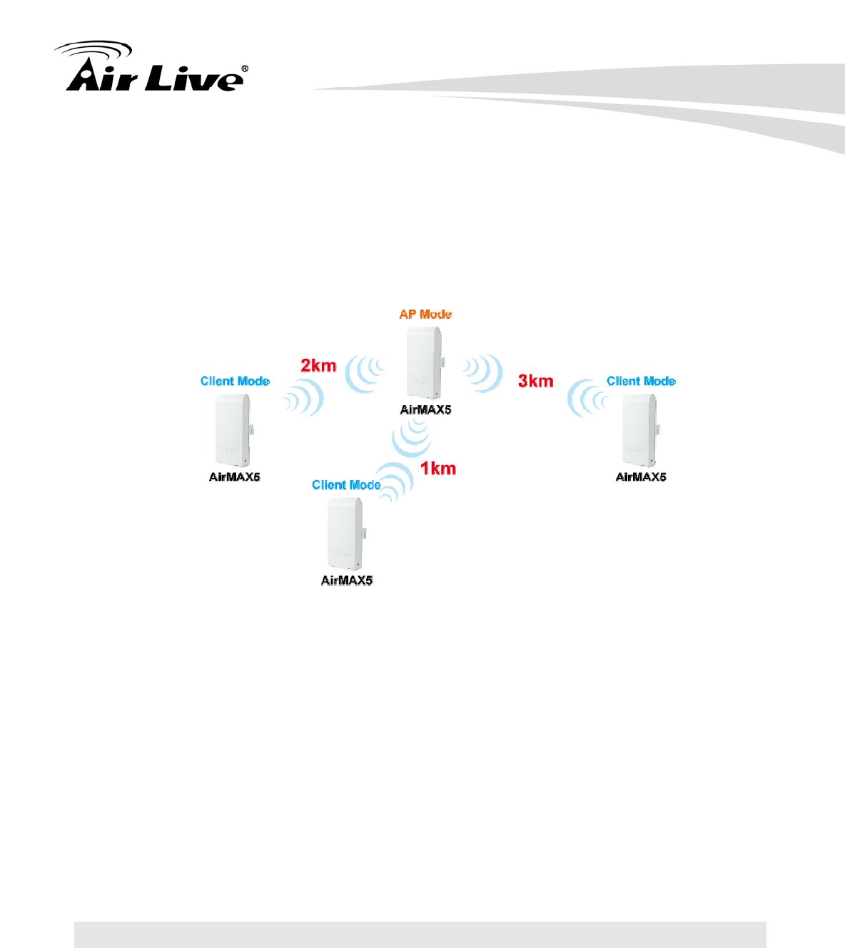
It is important to align your antenna correctly with the remote device to get the best signal
and performance. The AirMax5 is equipped with a 14dBi antenna with dual diversity. In
this chapter, we will first explain the design and function of the built-in antenna. Then we
will talk about 2 different ways for antenna alignment:
Using the LED Indicators: The AirMax5 has 2 LED indicators to show the current
signal strength of the connection. By having the 2 LED displayed in 4 different states,
you can easily know the signal strength of your antenna without the need to use a PC.
Using Signal Survey tool: The AirMax5 has a special Signal Survey tool inside the
Site Survey function. It will display a remote AP/Bridge’s signal strength level while
you adjust the antenna angle. If you can have a notebook attached while doing
antenna alignment, this method can tell you the precise RSSI level.
We will provide instructions on the two alignment methods later in this chapter. It is
recommended that you read through 4.2.12 on how to change antenna settings, and 4.2.20
about the RSSI LED Threshold before reading this chapter.
7.1 About AirMax5’s Antenna
The AirMax’s built-in antenna has the following characteristics:
Gain: 14dBi
Type: Patch Antenna
Polarization: Vertical, Horizontal, or Diversity.
H-Plane Coverage Angle: 30 degree forward
7 7. Antenna Alignment
7. Antenna Alignment
AirLive AIRMAX5 User’s Manual 104
E-Plane Coverage Angle: 30 degree forward
7.1.1 Polarization
The AirMax5 is equipped with 2 x 14dBi patch antennas; one antenna in horizontal
polarization and one in vertical polarization. For 2 wireless devices to connect, their
antennas must use the same polarization.
Vertical: The polarization of the antenna is vertical, in the same direction as the
AirMax5. This settings is the default and most used.
Horizontal: The polarization of the antenna is horizontal, 90 degree from the
direction of the case.
Diversity: The AirMax5 will auto switch between vertical and horizontal
antennas based on the RSSI level detected. However, the performance can
suffer if the switching happens too frequently
7. Antenna Alignment
105 AirLive AIRMAX5 User’s Manual
Please make sure there is no polarization mismatch when settings up
the wireless link
Antenna Settings: You can change the settings for the antenna from
“Operation Modes -> Setup -> Advance Settings” menu.
7.1.2 Mounting Adjustment
The degree you can adjust the AirMax5’s antenna depends on what mounting kit you use:
Standard Mounting: The standard strap mount
allows you to rotate the CPE in the horizontal plane
only. As long as 2 wireless devices are at about the
same elevation, this adjustment is already enough.
Optional Metal Mounting Kit: The optional metal
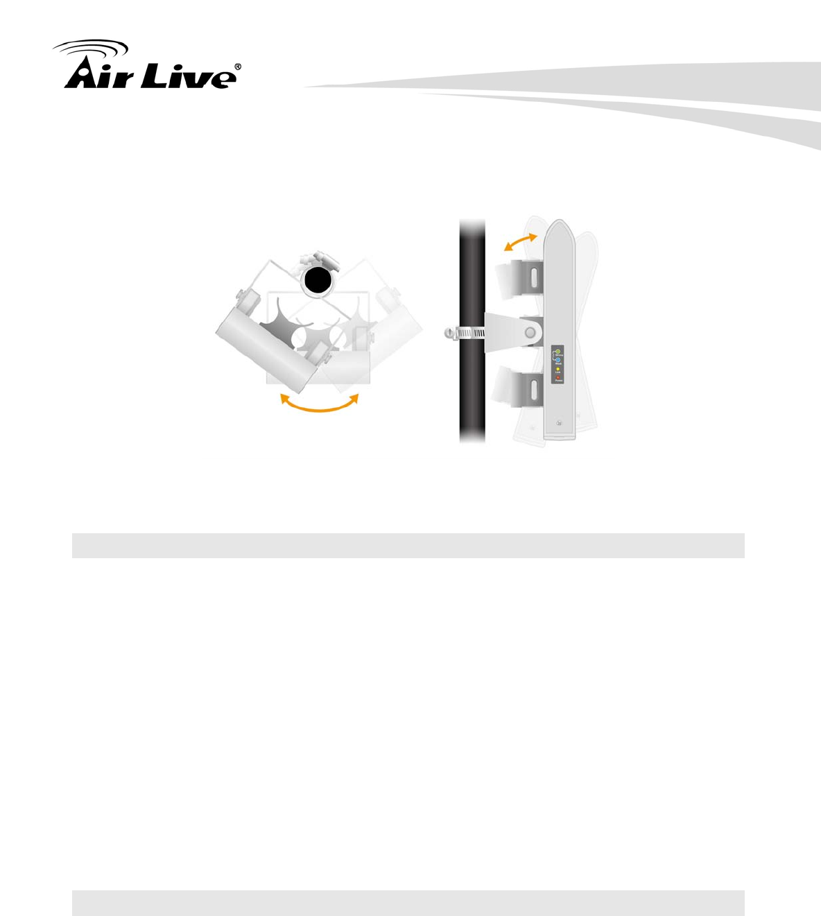
7. Antenna Alignment
AirLive AIRMAX5 User’s Manual 106
mounting kit allow the AirMax5 to rotate in both horizontal (pole mount only) and
vertical direction. It is recommended to use this mounting kit when there is a big
elevation difference between 2 sides of the wireless connection.
7.2 About RSSI Signal Level
The RSSI level is used to indicate the signal strength of the remote wireless device.
Therefore, the idea is to adjust the antenna until the RSSI level is at the highest. The unit
used by RSSI is in dB or dBm. Here are the general guidelines for RSSI
The smaller the absolute value of the RSSI, the strong the signal. For example,
-50dB is much stronger than -80dB
The most optimal RSSI range is between -50dB to -65dB
Signal weaker than -80dB (e.g. -85dB) is considered to be very weak.
Signal weaker than -85dB (e.g. -90dB) will most likely result in disconnection.
Signal stronger than -35dB (e.g. -30dB) is considered to be too strong. It might
result in near field effect and reduce the performance.
7.3 Preparation before Installation
The antenna alignment is for small adjustment only, you should not use it find remote AP.
The correct way is to use a satellite map program like “Google Map” to find the locations of
the installation site and the nearest AP/Bridge. Then measure the approximate direction
and angle. It will also help to bring a pair of hi power binocular for sight survey.
7. Antenna Alignment
107 AirLive AIRMAX5 User’s Manual
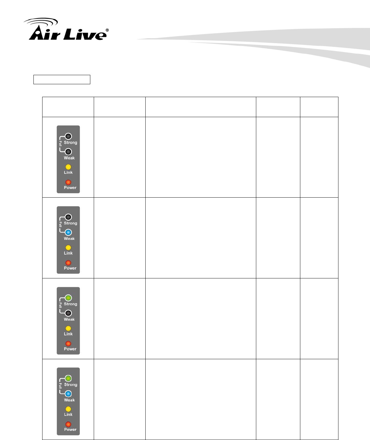
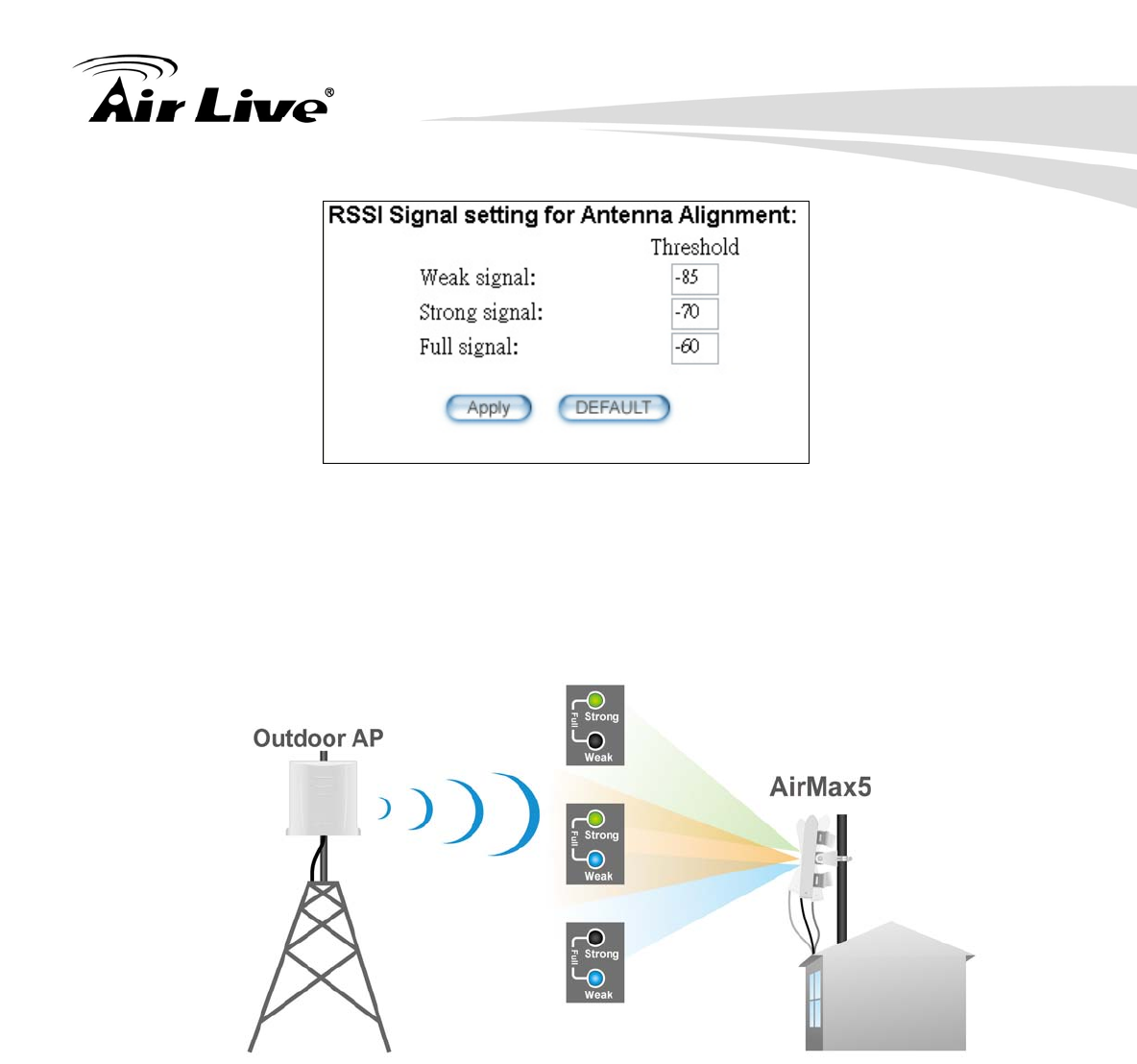
7.4 Antenna Alignment using RSSI LED
There are 2 LED indicators on the side of the AirMax5 that is dedicated to display the RSSI
signal strength. They are in bright blue and green color so you can see the difference in
signal far away from the CPE. By varying the states of the LED, the AirMax5 can display 4
different levels of signal strength.
About the Signal Threshold
There are total of 4 signal levels in AirMax5: No Signal, Weak Signal, Strong Signal, Full
Signal. The Signal Threshold is the dividing line between 2 signal level. For example; if
the Full Signal Threshold is set to -50dB, -49dB will be Full Signal while -51dB will be
Strong Signal.
You can change the Signal Threshold by going to going to “Operation Mode -> Setup ->
RSSI LED Threshold” menu. The values indicated are the default threshold value. The
correct value really depends on the TX output power of the remote AP. These values are
best for distance link about 2 kilometer with a remote AP of about 40dBm combined output
power with antenna. If the distance is greater or output power is lower, please reduce the
threshold values.
7. Antenna Alignment
AirLive AIRMAX5 User’s Manual 108
RSSI LED Table
LED Status Signal Level Description Default
Threshold Example
Values
No Signal When signal strength is less
than “Weak Signal Threshold” .
Both LED are off.
-80dB
(Weak
Signal
Threshold)
-85dB
Weak Signal When signal strength is greater
or equal than the “Weak Signal
Threshold”. Only the Blue
LED is on.
-80dB -75dB
Strong
Signal When signal strength is greater
or equal than the “Strong
Signal Threshold”. Only the
Green LED is on.
-60dB -55dB
Full Signal When signal strength is greater
or equal than the “Full Signal
Threshold” (i.e. -45dB). Both
Green and Blue LEDs are on
-50dB -45dB
7. Antenna Alignment
109 AirLive AIRMAX5 User’s Manual
Antena Alignment Procedures using RSSI LED
The RSSI LED will only function when the wireless link is established.
Therefore, you should enter all the wireless settings correctly before
installation. So the connection will establish while doing antenna
adjustment.
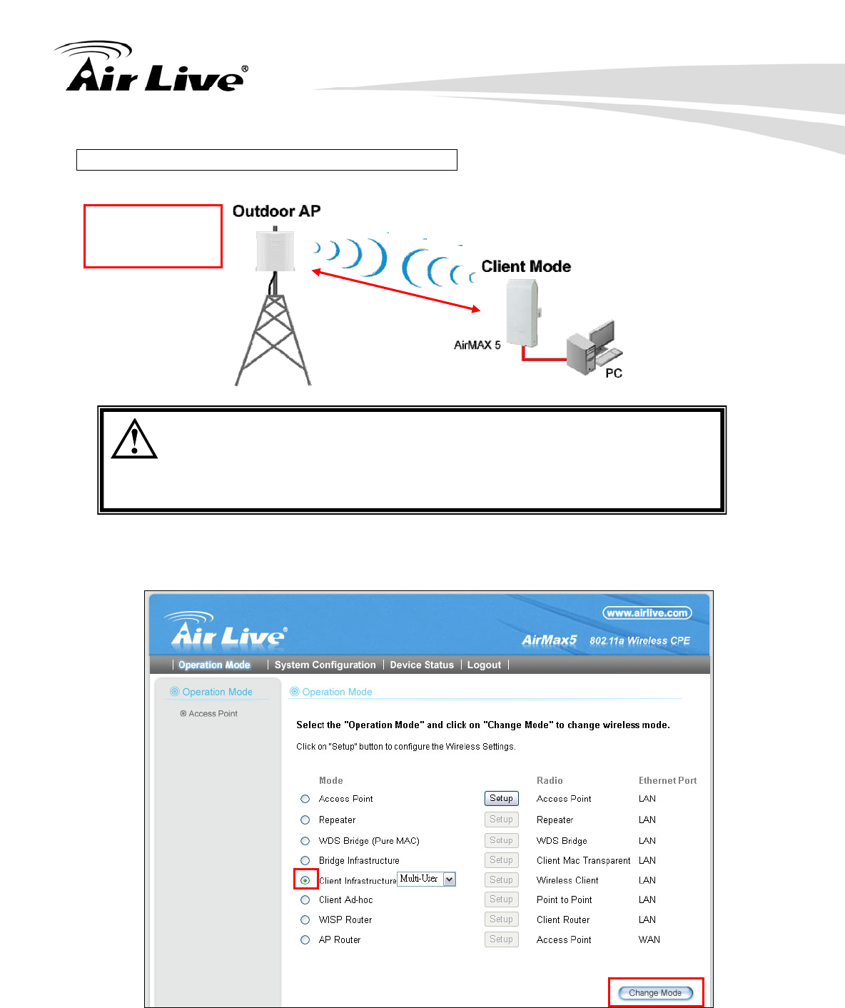
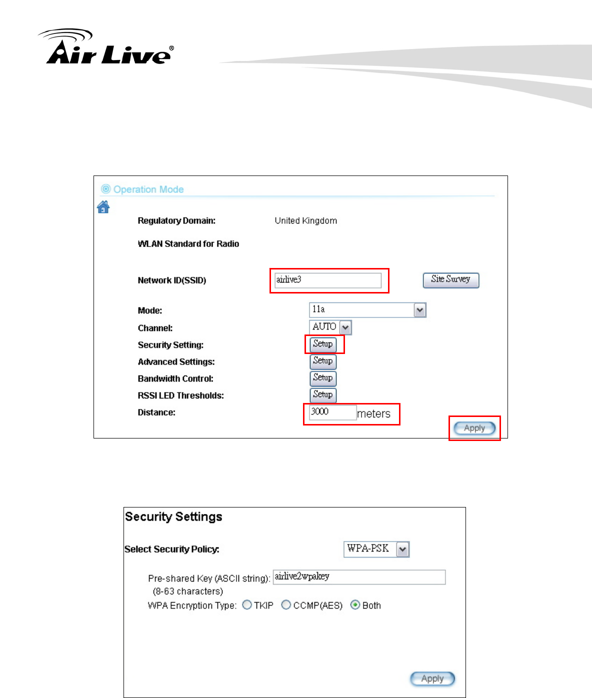
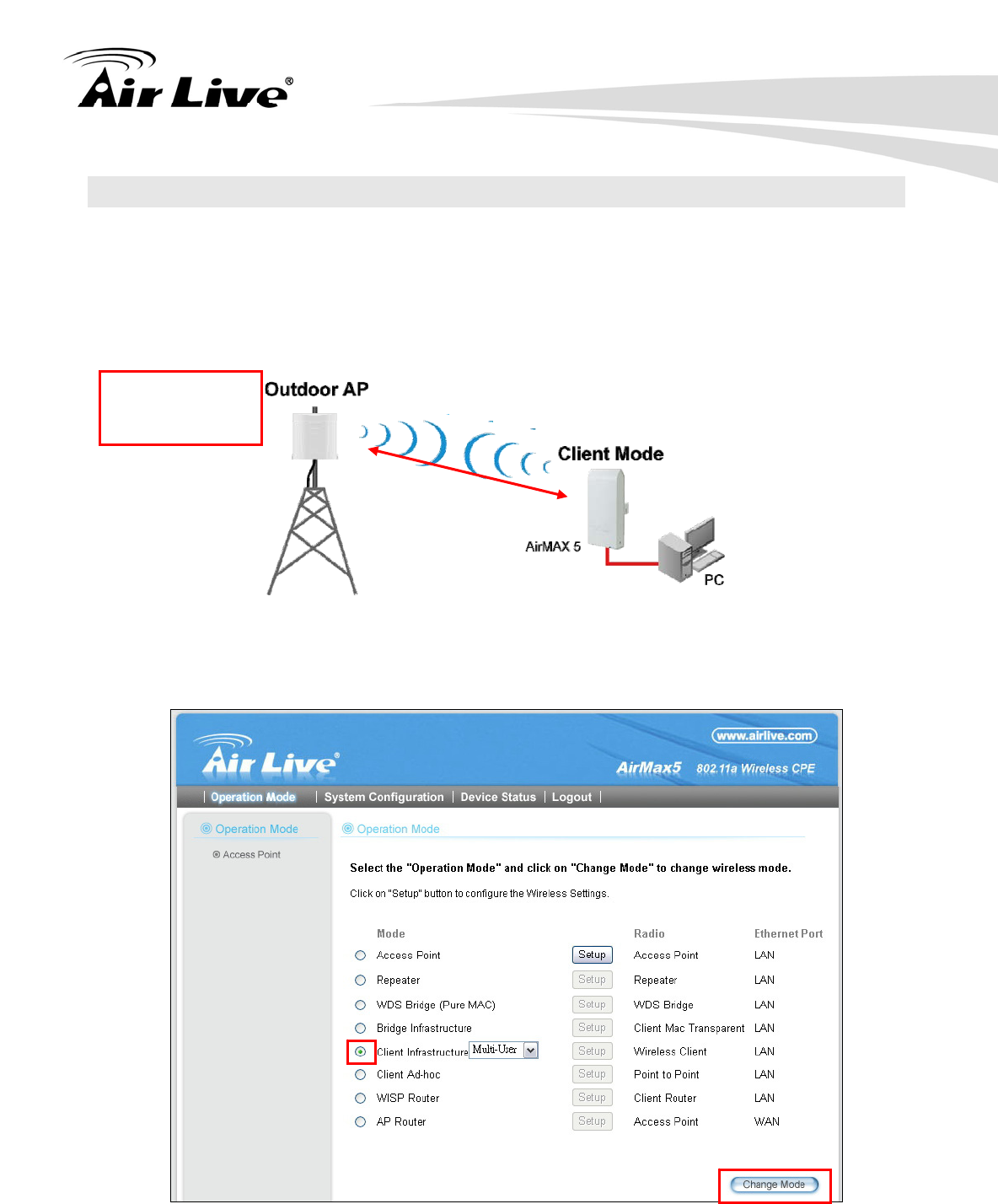
Step 1 Configure the AirMax 5 to Client Infrastructure Mode
Step 2 Press “Setup” to enter the wireless setting page
SSID: airlive3
Encryption:
WPA-PSK
3 km
7. Antenna Alignment
AirLive AIRMAX5 User’s Manual 110
Step 3 Enter the Networks SSID and distance information on the page. Click on “Apply”
button, and then press “Setup” button on Security Setting.
Step 4 Enter the security policy key information, then click on “Apply” button
Step 5 Go back to the wireless settings page and click on “RSSI LED Threshold” button.
Because the link is 3km, adjust the RSSI values as below then click “apply”
7. Antenna Alignment
111 AirLive AIRMAX5 User’s Manual
Step 6 Now, you can take the AirMax5 to the installation site and adjust the antenna by
looking at the LED indicator. You might never get the full signal, but you can find
the best position where the signal is strongest.
7. Antenna Alignment
AirLive AIRMAX5 User’s Manual 112
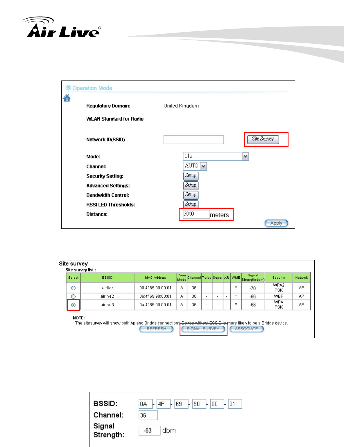
7.5 Antenna Alignment using Signal Survey
Signal Survey function can display the RSSI value in real time to help you with antenna
alignment. Because Signal Survey is a subnet of the Site Survey function, you do not
need to enter the wireless settings in advance. Please follow the example below to
complete antenna alignment using Signal Survey function.
Step 1 Configure the AirMax 5 to Client Infrastructure Mode
Step 2 Press “Setup” to enter the wireless setting page
SSID: airlive3
Encryption:
WPA-PSK
3 km
7. Antenna Alignment
113 AirLive AIRMAX5 User’s Manual
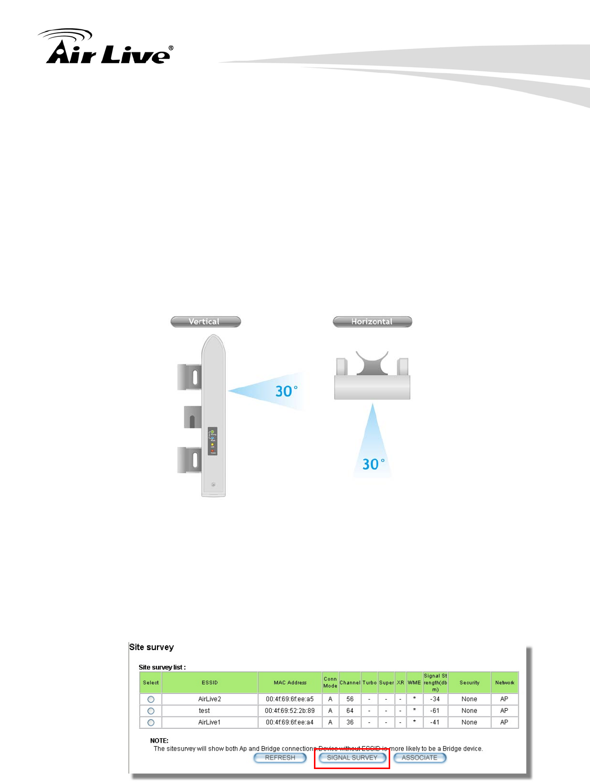
Step 3 Enter the “Distance” information and then click on Apply button. Then select
“Site Survey” to scan for available Access Point in the area.
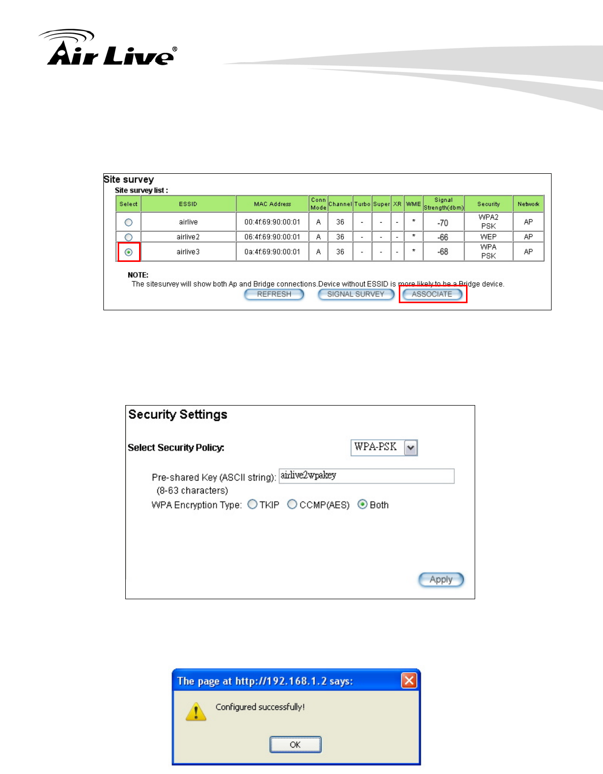
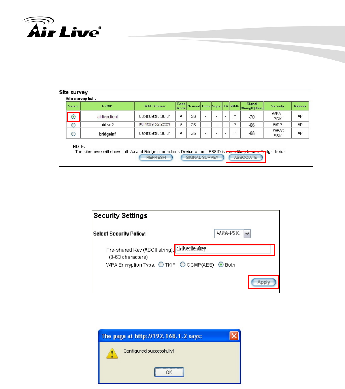
Step 4 The following Site Survey screen will appear. Please select “airlive3” and then
press the “Signal Survey” button
Step 5 The signal survey screen will appear. The RSSI value will refresh itself every
second. Adjust the antenna until the Signal Strength is at its strongest (the lower
the absolutely value, the stronger the signal: for example -60 is stronger than -70)
7. Antenna Alignment
AirLive AIRMAX5 User’s Manual 114
Step 6 Once the antenna position founds its strongest signal; go back to Site Survey
page. Select “airlive3”, and then press “associate” to connect.
Step 7 If the network you selected needs encryption, the following page will pop-up.
Please enter the correct encryption key and press “Apply” to finish
Step 8 The system will pop up a message telling you configuration is successful.
8. Application Example: Infrastructure
115 AirLive AIRMAX5 User’s Manual
In this chapter, you will learn how to utilize AirMax5’s Access Point mode, Client
Infrastructure Mode, and Bridge Infrastructure mode in one application example. In
addition, you will also learn how to configure multiple SSID and bandwidth control.
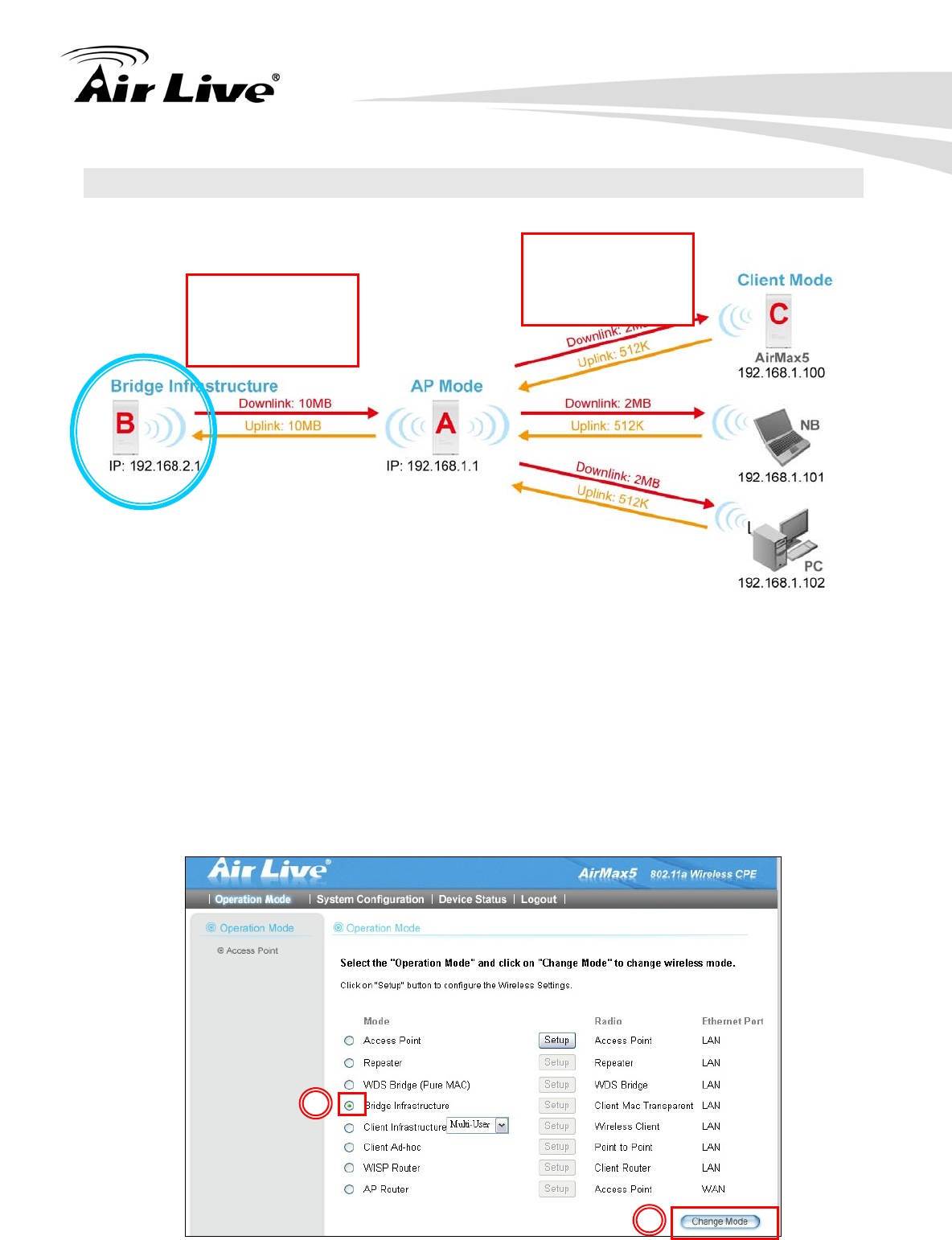
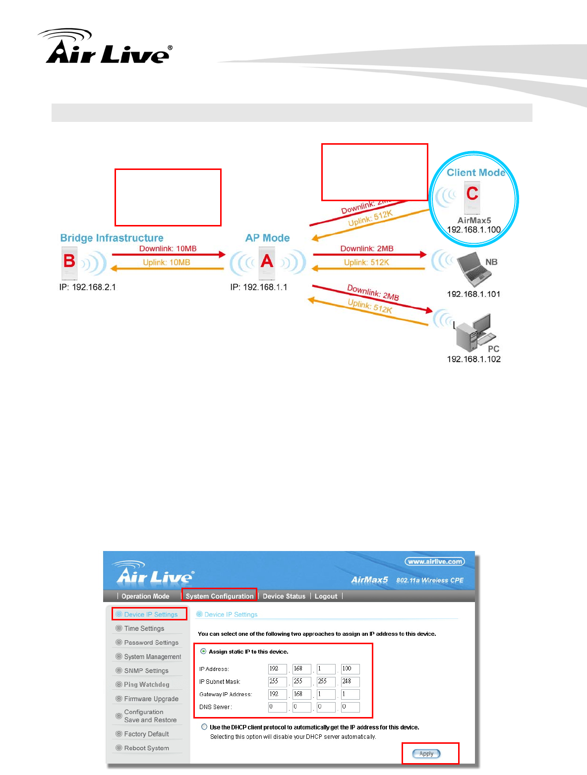
8.1 Application Environment
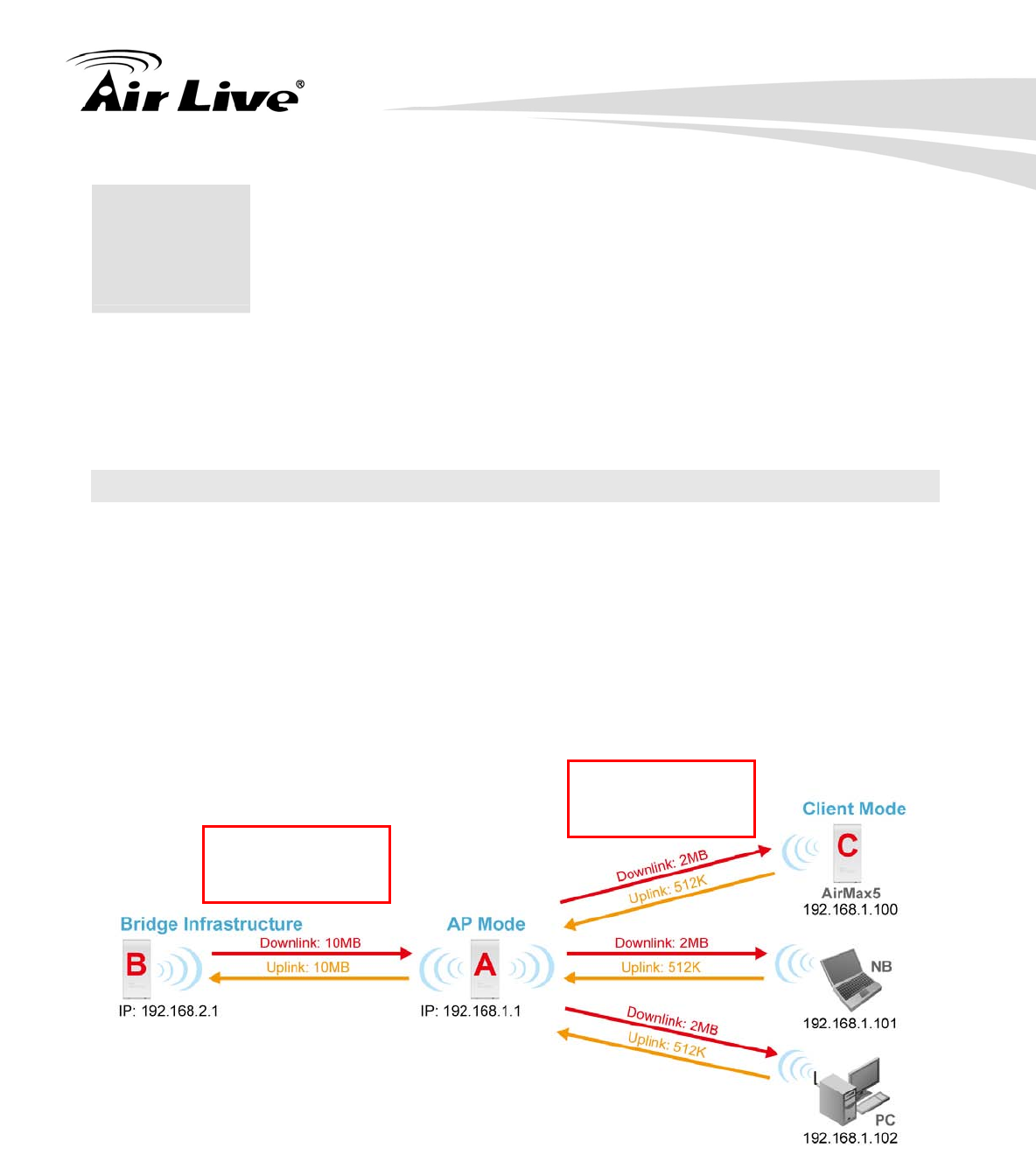
In this application example, an AirMax5 in Access Point mode is in the center of an
infrastructure topology with two virtual wireless networks. The first wireless network is the
AP-Client network and the second network is the Bridge network. Each wireless network
has its own SSID, security Policy and Bandwidth policy. On the left hand side is an
AirMax5 in Bridge Infrastructure mode. On the right hand side are an AirMax5 (Client
Mode), a notebook, and a PC.
Below is the general description about the devices of the network.
Device A: AirMax5 in Access Point Mode
Using multiple SSID to create 2 wireless network
airliveclient: A network for wireless clients with WPA-PSK security policy.
bridgeinf: A bridge network with WPA-PSK2 security policy
Enable Per-User bandwidth Control for the “airliveclient” network
The wireless client network will be limited to a subnet of 6 IP addresses.
Each IP address will be limited to 512Kbps upload and 2MB download speed.
8 8. Application Example:
Infrastructure
SSID: airliveclient
Encryption:
WPA-PSK
SSID: bridgeinf
Encryption:
WPA-PSK2
8. Application Example: Infrastructure
AirLive AIRMAX5 User’s Manual 116
Device B: AirMax5 in Bridge Infrastructure Mode
Using Total bandwidth Control to limit the Bridge traffic to 10Mbps both way.
Use Site Survey wizard to make the connection in a simple one stop process.
Device C: AirMax5 in Client Infrastructure Mode
Connect to the Access Point using Client Infrastructure Multiple User mode.
Use Site Survey to connect and associate with the AP.
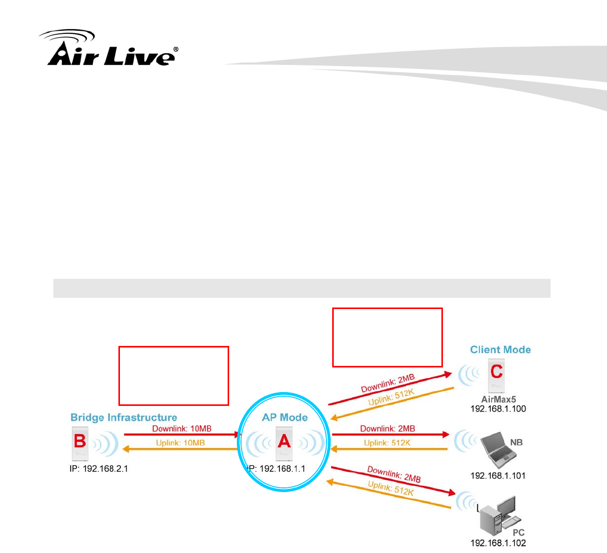
8.2 Device A: Access Point Mode
The configuration of Device A involves the followings:
Using multiple SSID to create 2 wireless network
airliveclient: A network for wireless clients with WPA-PSK security policy.
bridgeinf: A bridge network with WPA-PSK2 security policy
Enable Per-User bandwidth Control for the “airliveclient” network
The wireless client network will be limited to a subnet of 6 IP addresses.
Each IP address will be limited to 512Kbps upload and 2Mbps download speed.
SSID: airliveclient
Encryption:
WPA-PSK
Distance: 2000m
SSID: bridgeinf
Encryption:
WPA-PSK2
Distance: 2000m
8. Application Example: Infrastructure
117 AirLive AIRMAX5 User’s Manual
8.2.1 Device A Wireless Settings
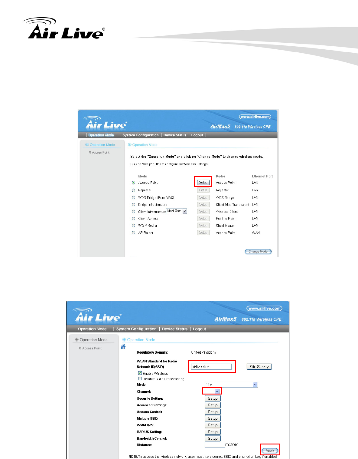
Step 1 Click on “setup” button on the “Operation Mode” page
Step 2 On the wireless setting page, please enter the SSID, Channel, and distance.
Then press “Apply” to make changes.
100
2000
8. Application Example: Infrastructure
AirLive AIRMAX5 User’s Manual 118
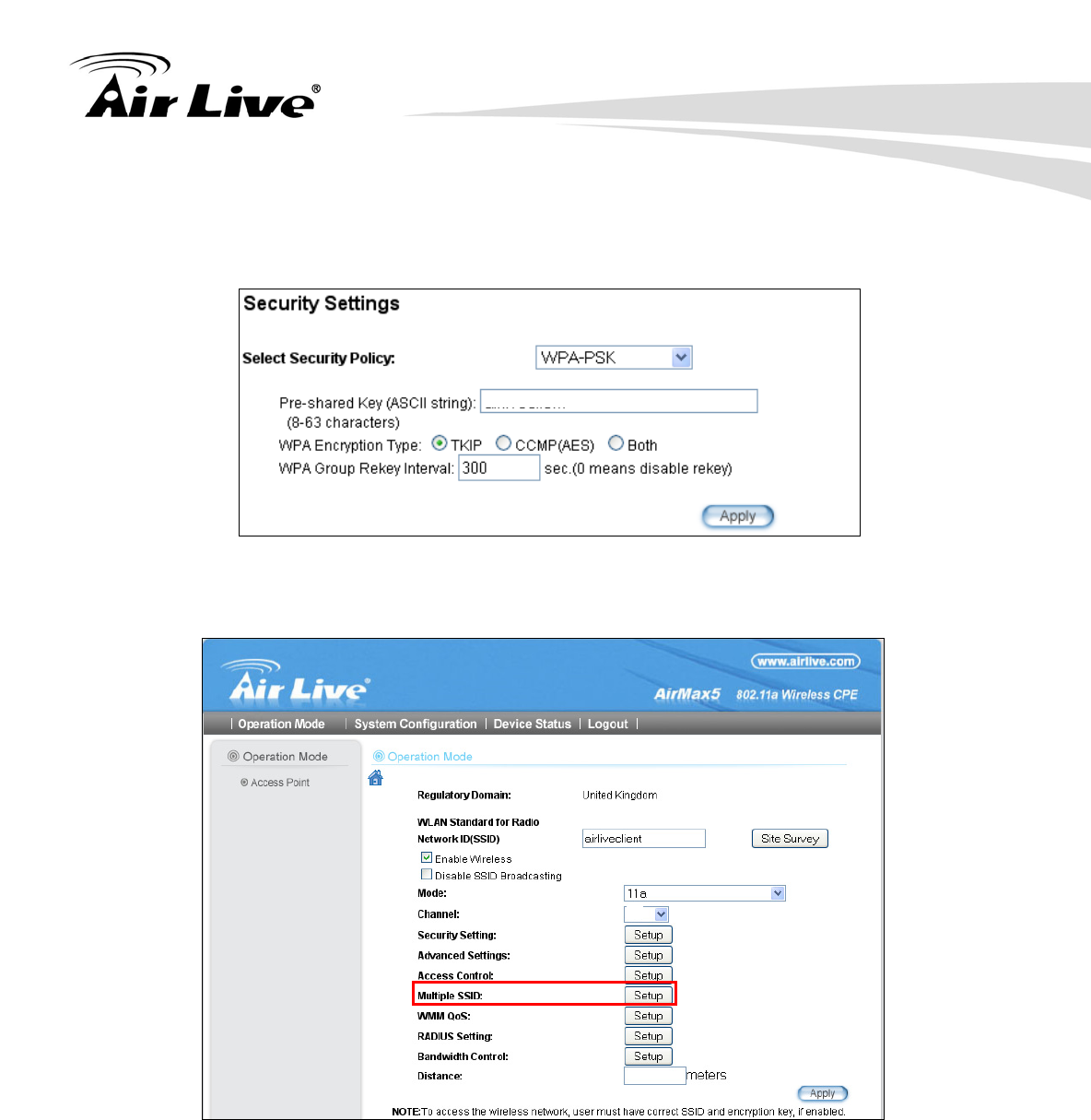
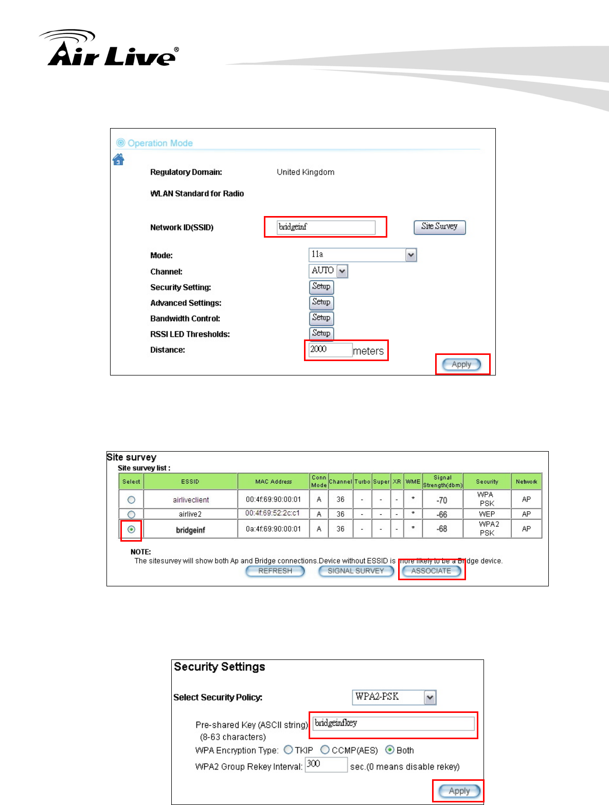
Step 3 Click on the “Security Settings”. Then choose “WPA-PSK” Policy. Enter the
“airliveclientkey” as the pre-share key.
Step 4 Go back to the wireless setting page and click on “Multiple SSID” button
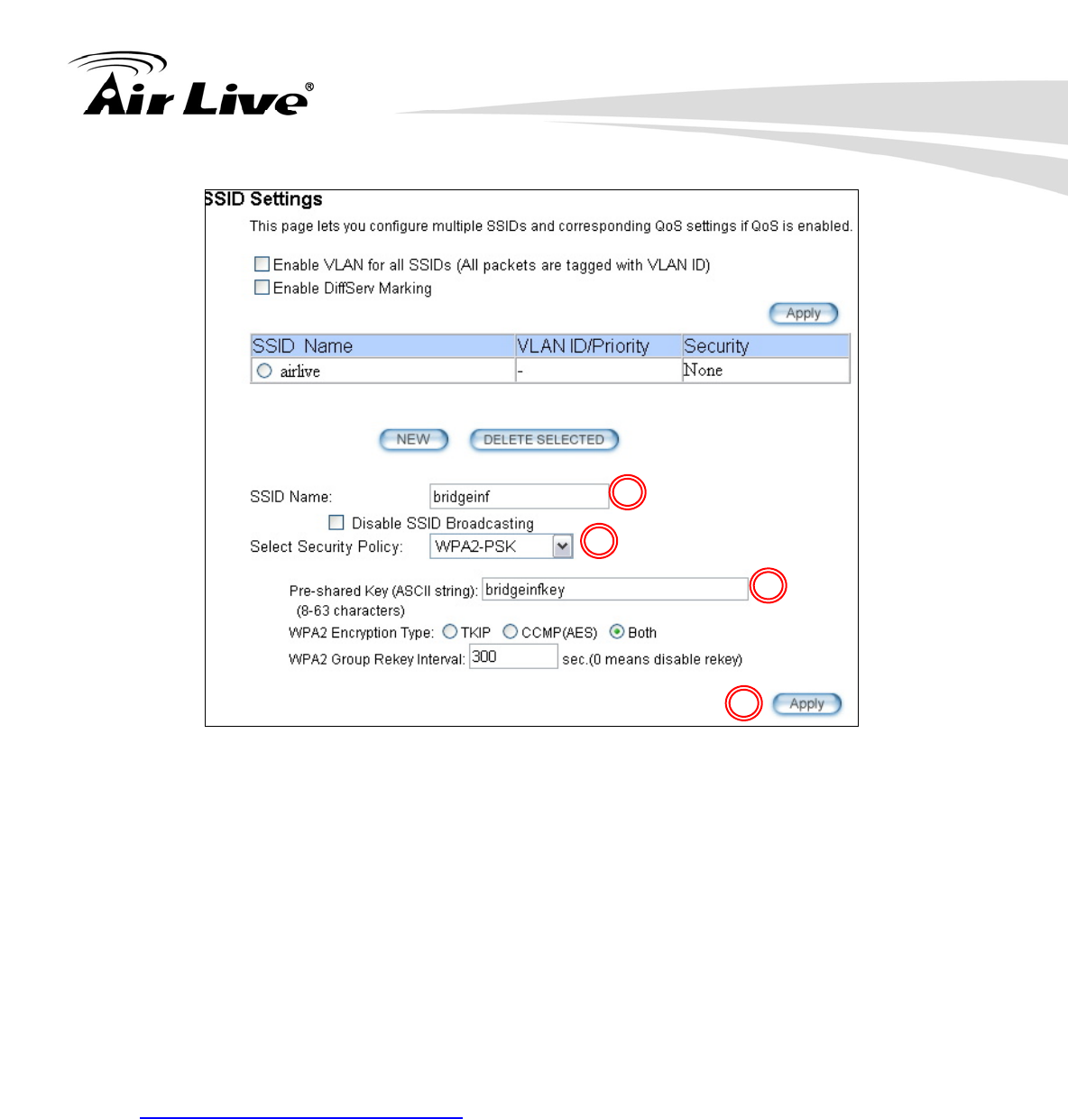
Step 5 Follow the procedure below to create a new SSID “bridgeinf”
1. Enter the SSID name “bridgeinf”
2. Select WPA-PSK as the security policy
3. Enter the pre-share key as “bridgeinfkey”
4. Click on “Apply” to add
100
2000
airliveclientkey
8. Application Example: Infrastructure
119 AirLive AIRMAX5 User’s Manual
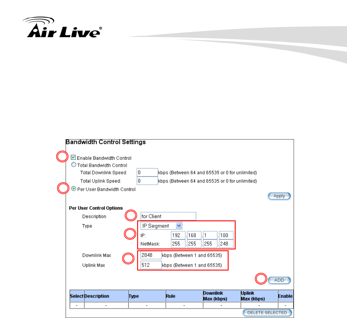
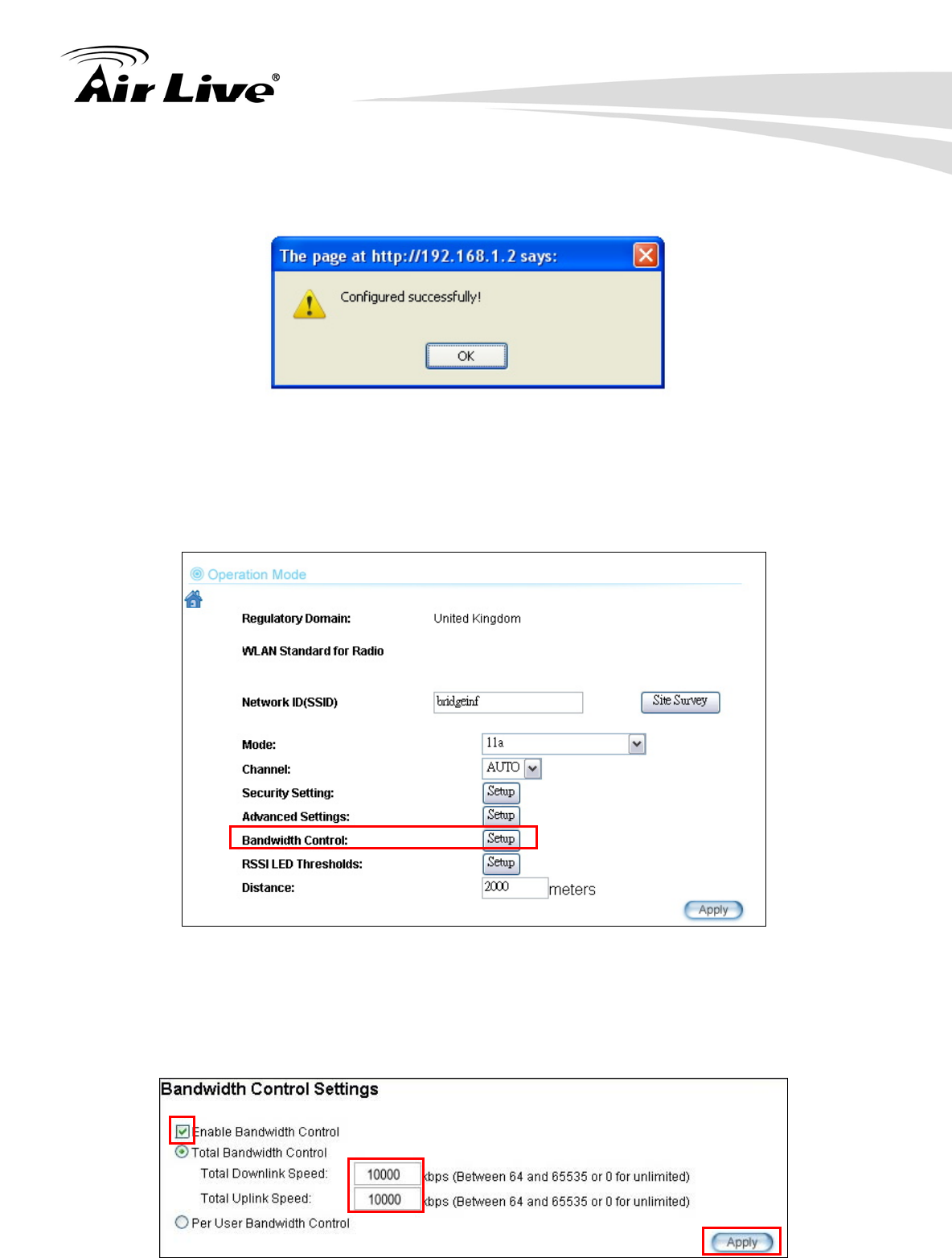
8.2.2 Device A Bandwidth Management
This purpose is to limit the bandwidth of each wireless client in “airliveclient” network to
have a download bandwidth of 2048kbps and upload speed of 512kbps. We should set
the policy as followed.
Set the Per-User Bandwidth Control by “IP Segment”. The IP segment here has
address of 192.168.1.100 with subnet mask of 255.255.255.248. The available host
IP addresses will be 192.168.1.96 to 192.168.1.02. If you are not familiar with IP
subnet calculation, please use an on-line IP calculator. Here is an example link:
http://www.subnet-calculator.com/
Set the uplink as 512kbps, downlink as 2048mbps
Step 1 Select the “Bandwidth Control” from the “Operation Mode->Setup” menu
Step 2 Once you have entered the Bandwidth Control menu, please follow the steps
below
1. Enable Bandwidth Control
1
2
3
4
8. Application Example: Infrastructure
AirLive AIRMAX5 User’s Manual 120
2. Select “Per-User Bandwidth Control.
3. Enter “for client” in description
4. Select “IP Segment. Enter 192.168.1.100 for IP, and “255.255.255.248” for
subnet mask.
5. Enter 2048 for downlink and 512 for uplink
6. Click on “Add” to add the bandwidth policy.
Note: Because the Bandwidth Control will limit devices on both wireless and Ethernet
side, it is recommended to set the IP address of Ethernet side to have a larger IP scope so
it will not be limited by the IP segment policy. In this example, please set the devices on
the Ethernet side to have subnet mask of 255.255.255.0.
1
2
3
4
5
6
8. Application Example: Infrastructure
121 AirLive AIRMAX5 User’s Manual
8.3 Device B: Bridge Infrastructure Mode
The configuration settings on the Device B will be as followed
Set it to “Bridge Infrastructure Mode”
Use “Site Survey” function to associate and connect with the Device A.
Set “Total Bandwidth Control” to limit the bandwidth to 10Mbps both upstream and
downstream
8.3.1 Device B Wireless Settings
Step 1 Select “Bridge Infrastructure” mode and Click on “change mode” button
SSID: airliveclient
Encryption:
WPA-PSK
Distance: 2000m
SSID: bridgeinf
Encryption:
WPA-PSK2
Distance: 2000m
2
1
8. Application Example: Infrastructure
AirLive AIRMAX5 User’s Manual 122
Step 2 Enter the Network ID(SSID) and distance information. Then click on “Apply”
Step 3 Click on “Site Survey” in wireless settings page and the following screen will
appear. Select “Bridgeinf”, then press “ASSOCIATE” button to connect.
Step 4 The AirMax5 will prompt you to enter security policy information. Select
WPA2-PSK and enter “bridgeinfkey” for Pre-Shared Key.
8. Application Example: Infrastructure
123 AirLive AIRMAX5 User’s Manual
Step 3 Click on “Apply”. After a few seconds, the following screen will appear to show
successful connection.
8.3.2 Device B Total Bandwidth Control
Step 1 Select “Bandwidth Control” from the wireless setting page.
Step 2 Enable Bandwidth Control, then select Total Bandwidth Control. Enter
10000Kbps (10Mbps) for both downlink and uplink bandwidth. Click on Apply to
finish.
8. Application Example: Infrastructure
AirLive AIRMAX5 User’s Manual 124
8.4 Device C: Client Infrastructure Mode
Device C: AirMax5 in Client Infrastructure Mode
Set device IP to 192.168.1.100 with subnet mask of 255.255.255.248
Connect to the Access Point using Client Infrastructure Multiple User mode.
Use Site Survey to connect and associate with the AP.
8.4.1 Device C IP Address
Step 1 Go to “System Configuration -> Device IP settings”. Select “Assign Static IP to
this device”. Then enter the IP address and Subnet Mask as bellowed. Click Apply when
finished.
SSID: airliveclient
Encryption:
WPA-PSK
Distance: 2000m
SSID: bridgeinf
Encryption:
WPA-PSK2
Distance: 2000m
8. Application Example: Infrastructure
125 AirLive AIRMAX5 User’s Manual
8.4.2 Device C Wireless Settings
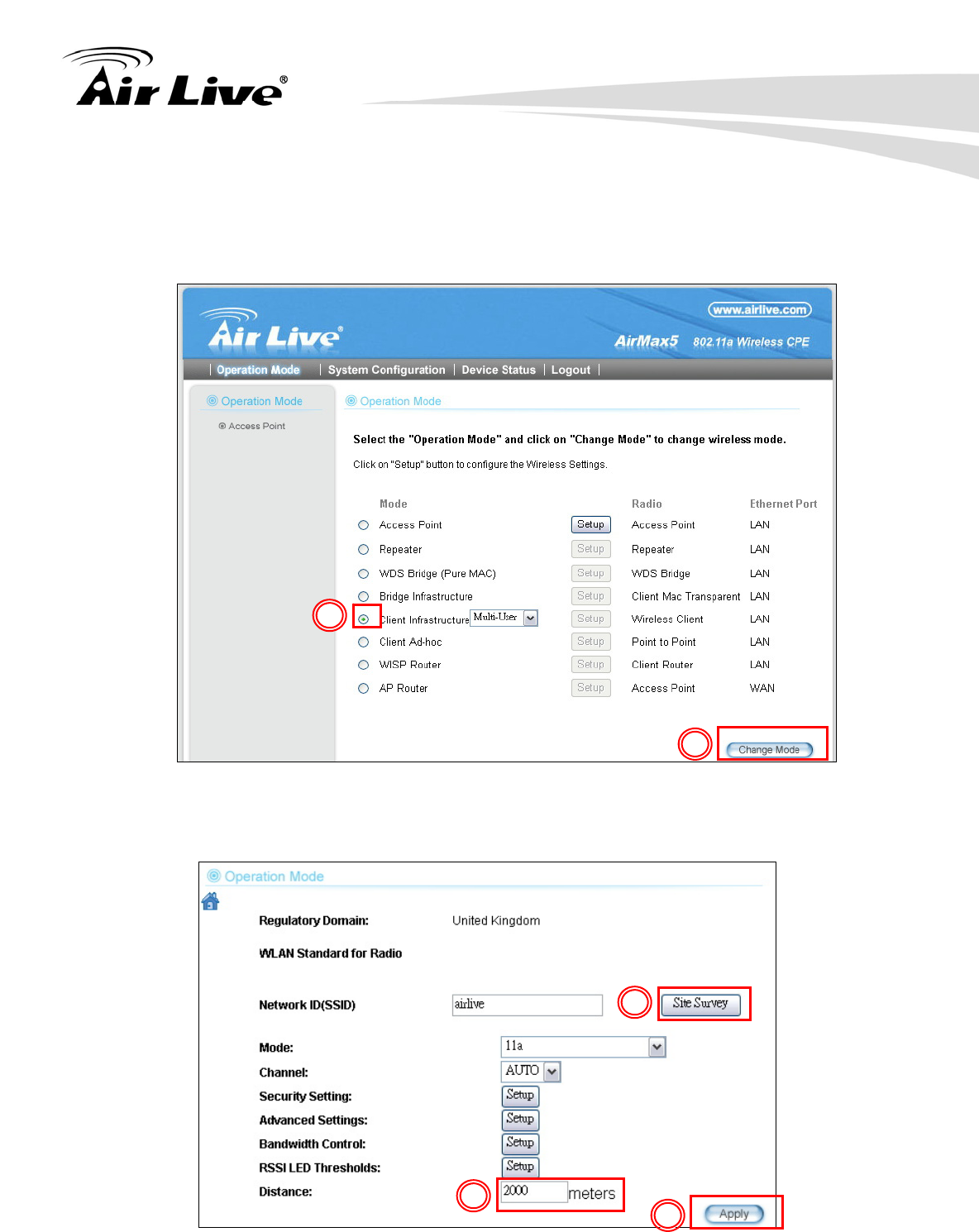
Step 1 Go to “Operation Mode” menu. Select “Client Infrastructure”, and then click on
“Change Mode” button.
Step 2 Press “Setup” to enter the wireless settings page. Enter the distance
information and click on “APPLY” button.
2
1
2
1
3
8. Application Example: Infrastructure
AirLive AIRMAX5 User’s Manual 126
Step 3 Press “Site Survey” button, the following page should appear. Select
“airliveclient” and press “Associate” button to connect
Step 4 The AirMax5 will prompt you to enter security policy information. Select
WPA-PSK and enter “airliveclientkey” for Pre-Shared Key.
Step 5 Click on “Apply”. After a few seconds, the following screen will appear to show
successful connection.
You have now setup a successful Infrastructure network with AirMax5 in Access Point,
Bridge Infrastructure, and Client Infrastructure modes

9. Application Example2: Bridge Network
127 AirLive AIRMAX5 User’s Manual
Before reading this chapter, please read section 4.3 first on WDS settings. In this chapter,
you will learn to how to build a WDS Bridge network by following our step by step example.
In addition, we will talk about the general concepts and knowledge about building a long
distance connection.
This chapter is divided into 3 sections
9.1: Preparation for Building Outdoor Bridge Networks: This section provides
basic knowledge about building long distance outdoor bridge connection.
9.2: WDS Bridge vs. Bridge Infrastructure: Here we will discuss the
differences between the 2 bridge mode.
9.3: WDS Bridge Network Example: A step-by-step guide to building a multiple
link Bridge network.
9.1 Preparation for Building Outdoor Bridge Networks
1. Write down the WLAN MAC address in advance
Please remember to write down the WLAN MAC addresses of the AP for installation.
The WDS bridge require to enter remote Bridge’s MAC address for WDS
authentication.
2. Always do a Google Earth search on the intended installation before departing
Please get information on location, elevation, and distance between the points of your
installation site
3. Bring a pair of high powered binoculars for site survey
You might often find that the installation points are difficult to find over long distance.
A pair of hi powered binocular will help finding the objects. Look for landmarks that
are easy to identify.
4. Bring Long Distance Walkie-Talkie System
There are hi-powered offering that can work over distance of 5km or more.
Communication is absolutely necessary on both sides during installation.
5. You need a clear Line of sight
9 9. Application Example 2:
Bridge Network

9. Application Example2: Bridge Network
AirLive AIRMAX5 User’s Manual 128
More than 60% of First Fresnel Zone must be cleared for acceptable performance.
6. Secured Mounting is important
If the mounting is not secured and shakes during wind, the performance might be
drastically reduced.
7. Remember to set correct Distance for long distance connection
Without setting the correct distance parameter (or ACKtimeout), the Bridge might not
even transmit data at all.
8. Use just enough output power
Excessive output power not only creates serious interference for everyone, it actually
can reduce the performance. An RSSI value around 60dB provides the optimal
performance.
9. Always do a site survey for antenna alignment
Most AirLive APs have site survey and signal survey function. Some even have LED
indicators to show signal strength (WLA-9000AP, WH-9200AP, AirMax5). It is
important that the antennas are aligned properly. If you are setting up 5GHz bridge,
please use “11a” mode first for antenna alignment. You can change to Super or Turbo
mode after the connection is established.
10. Use the correct Super or Turbo modes
• 11a mode (normal-A): This is the IEEE standard for WiFi operating in 5GHz
frequency band. 11a is the most stable mode. If you are getting packet loss or
disconnection using Super-A orTurbo-A mode. Please use 11a mode instead.
• SuperA without Turbo: Super-A adds Bursting and Compression to increase the
speed over 11a mode. If you live in countries that prohibit the channel binding
technology (i.e. Europe), you should choose “Super-A without Turbo) if you need
more speed than 11a mode. However, this mode is not as stable as 11a mode or
Super-A with Turbo-A modes.
• Super-A with Static Turbo: Turbo mode uses channel binding technology to
increase the speed further over Super-A and 11-A mode. This mode might not be
allowed in countries that prohibit channel binding (i.e. some EU countries). This
mode will always turn on the turbo mode in al conditions
• Super-A with Dynamic Turbo: Dynamic Turbo mode will be turn on only when
adjacent channel is not used. It is also know as intelligent turbo mode. This mode
might not be allowed in countries that prohibit channel binding (i.e. some EU
countries).
9. Application Example2: Bridge Network
129 AirLive AIRMAX5 User’s Manual
11. For multi-point connection, use bandwidth control to manage the variable
distance problem
Using ACKtimeout for point-to-point connection is no problem. However, for
point to multi-point connection, it becomes a problem at the center point. In the
diagram below, the AirMax5 at point A is the center hub. While wireless clients at
B, C,and D can set correct ACKtimeout values to point A, the center AP can set
only one Acktimeout value.
To illustrate this problem; when you set the ACKtimeout at Point A to 2km distance.
The likely result will be Point B will get about 90% of the bandwidth, Point C gets 10%,
and Point D gets nothing at all.
To solve this problem, please use total bandwidth control at point B, C, D to limit the
bandwidth to about 40% of total bandwidth each maximum. Then set the AP’s(Point A)
ACKtimeout value to 3km distance (the furthest point). All 3 points should then get
acceptable share of the bandwidth.
12. Use XR mode when you can’t connect with the extra sensitivity
Atheros eXtended Range mode will improve the AP’s receiver sensitivity to as high as
-105dB. However, when this mode is used, the performance may be reduced greatly.
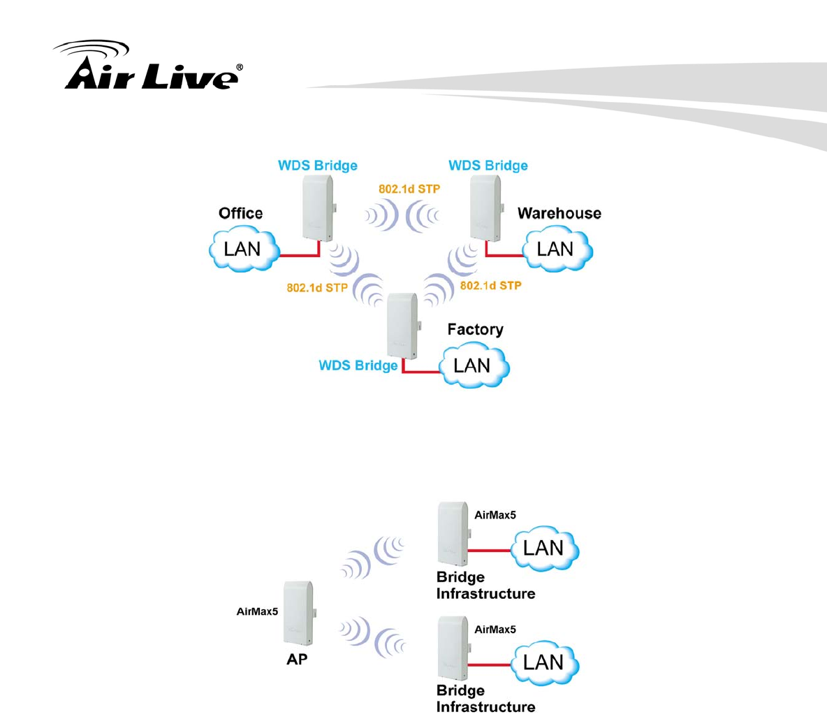
9.2 WDS Bridge vs. Bridge Infrastructure
When you want to build a bridge connection, there are 2 choices with AirMax5:
WDS Bridge (Pure MAC): WDS Bridge mode can make Point-to-Point and
Multi-Point connections. It also delivers faster performance than infrastructure
networks. In a WDS network, each node can have up to 4 connections but the total
number of devices should not exceed 8. Currently, the WDS Bridge mode can only
use WEP encryptions policy.
A
B
C
D
9. Application Example2: Bridge Network
AirLive AIRMAX5 User’s Manual 130
Bridge Infrastructure: Bridge Infrastructure mode connects to AP mode to form a
star topology. Bridge Infrastructure mode can not make a Point-to-Point connection.
However, it works with WPA-PSK and WPA2-PSK encryption. This mode is also
unknown as Client Mode with MAC Address Transparency.
When to use which bridge mode:
WDS Bridge Mode:
When you making point-to-point connection. For example, when you build
wireless bridge network between office and warehouse.
When you require fast performance
When you require multiple star topologies.
Bridge Infrastructure
When you are connection both Bridge network and wireless client to the remote
Access Point
When you require more advance security like WPA and WPA2
TIPS: For step-by-step instruction on how to setup Bridge Infrastructure mode, please go
to Chapter 8 Application Example: Infrastructure Mode.
9. Application Example2: Bridge Network
131 AirLive AIRMAX5 User’s Manual
9.3 WDS Bridge Network Example
In this WDS Bridge example, you will learn how to:
Setup the WDS settings
Set to use different encryption key for different Link
SSID’s function for WDS bridge
PING watchdog to maintain the WDS Link.
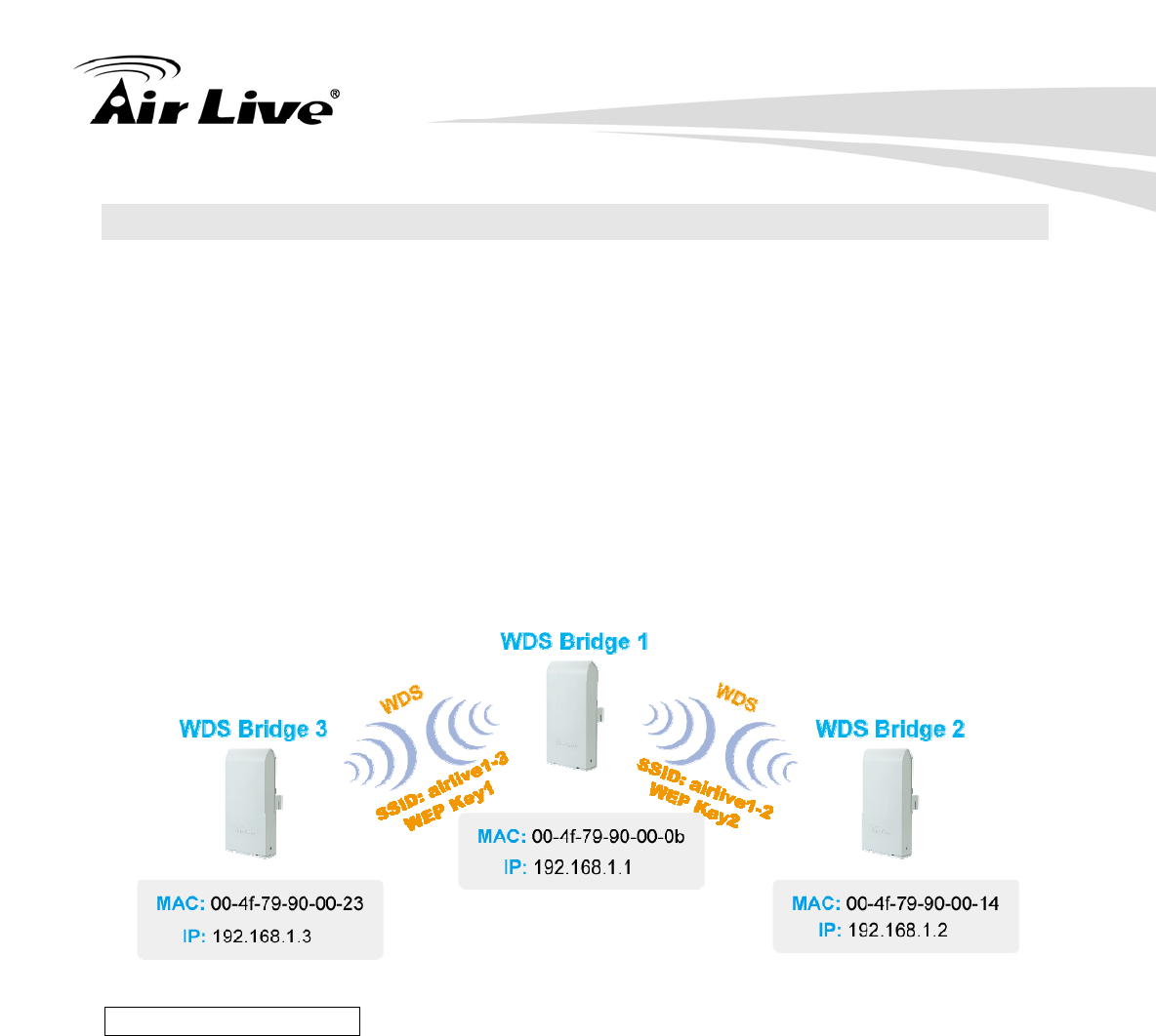
There are total of 3 bridges; with Bridge1 in the middle of Bridge 2 and Bridge 3.
The link between Bridge 1 and Bridge 3 will be using WEP Key 1 with SSID airlive1-3.
The link between Bridge 1 and Bridge 2 will be using WEP Key2 with SSID airlive1-2.
WDS Bridge 1 Settings
1. Enter the WEP Encryption Keys. You can enter 4 keys with different key-length
and key type. In this example, we have 4 WEP keys with WEP152-HEX,
WEP152-ASCII, WEP128-ASCII, and WEP64-ASCII. Click on “Apply” after
entering the keys.
2. Adding the first WDS Link to WDS Bridge 3
Name: WDS3
SSID: airlive1-3
MAC address: you should enter the MAC address of WDS Bridge 3:
00-4f-79-90-00-23
Select Security Policy: Select “WEP” encryption. The AirMax5 will ask you to
select which key to use. You can select same key or different key for different
WDS link (however, both side of the same link must use the same key). In this
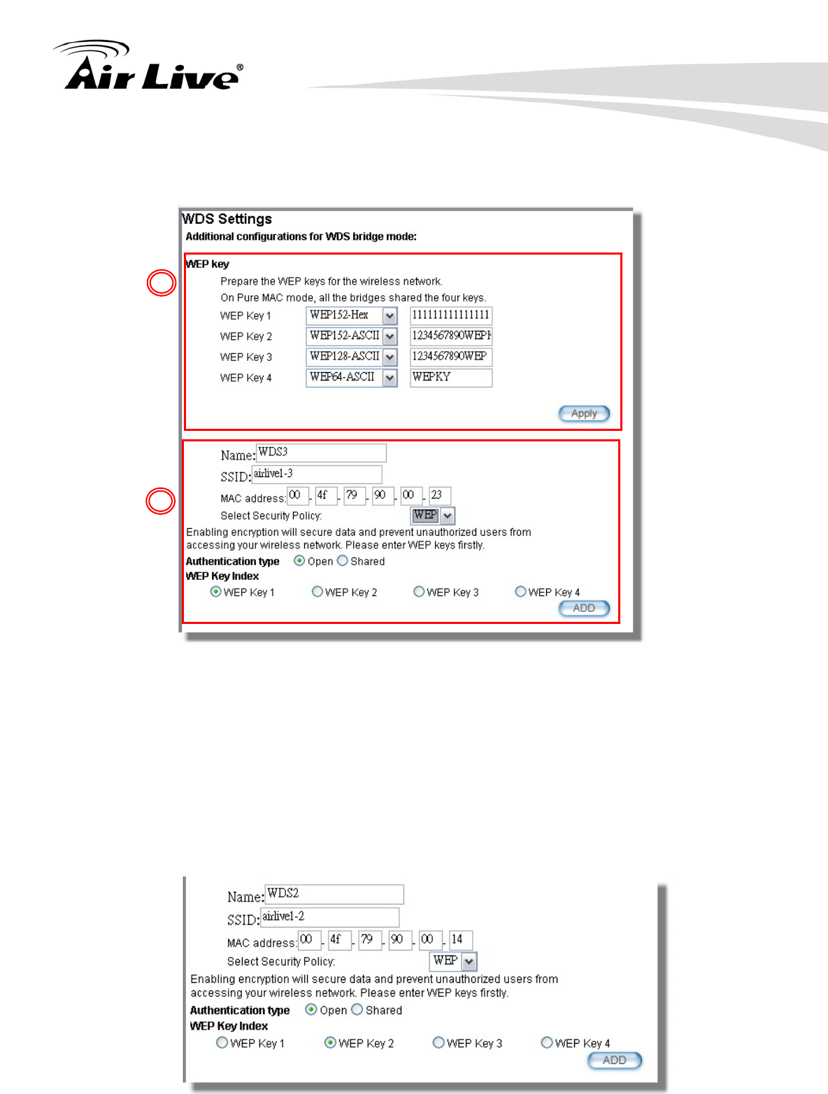
9. Application Example2: Bridge Network
AirLive AIRMAX5 User’s Manual 132
case, the Link between Bridge 1 and 3 is using Key1.
Click on “Add” to add the WDS Link.
3. Adding the second WDS Link to WDS Bridge 2
Name: WDS2
SSID: airlive1-2
MAC address: please enter the MAC address of WDS Bridge2:
00-4f-79-90-00-14
Select Security Policy: Select “WEP” encryption. The AirMax5 will ask you to
select which key to use. The Link between Bridge 1 and 3 is using Key2.
Click on “Add” to add the WDS Link.
1
2
9. Application Example2: Bridge Network
133 AirLive AIRMAX5 User’s Manual
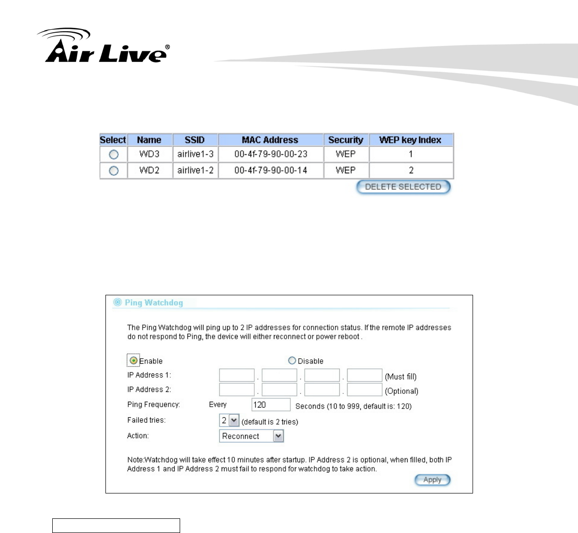
The following table will be displayed to show the added WDS links:
4. Setup the PING watchdog. Ping watchdog will reboot or reconnect the AirMax5
when the remote device does not respond to PING command. It helps maintain the
WDS Link. Please setup the PING watchdog according to graphic below:
.
WDS Bridge 2 Settings
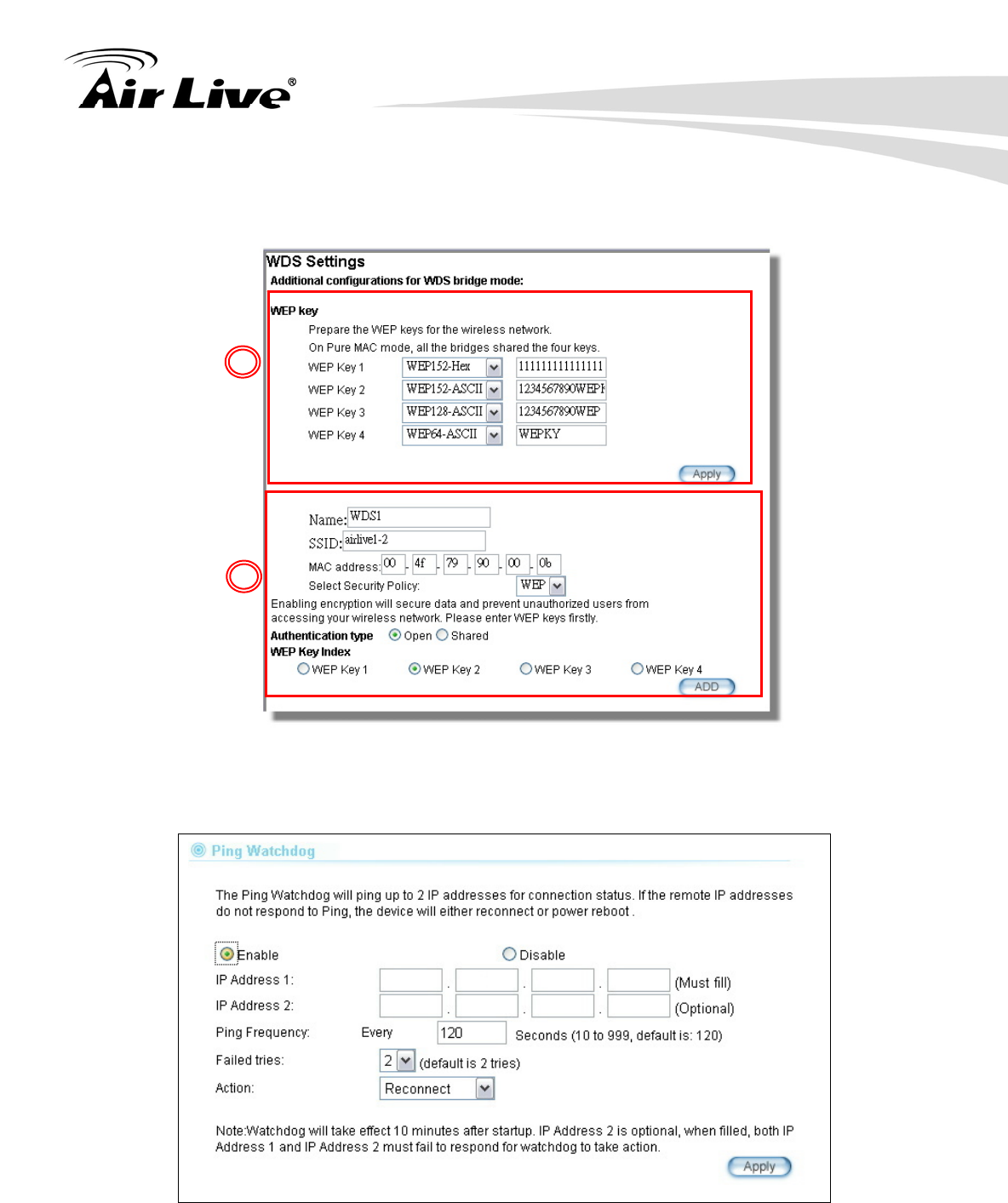
1. Enter the WEP Encryption Keys. In this example, we have 4 WEP keys with
WEP152-HEX, WEP152-ASCII, WEP128-ASCII, and WEP64-ASCII. Click on
“Apply” after entering the keys.
2. Adding the WDS Link to WDS Bridge 1
Name: WDS1
SSID: airlive1-2
MAC address: you should enter the MAC address of WDS Bridge 1:
00-4f-79-90-00-0b
Select Security Policy: Select “WEP” encryption. The AirMax5 will ask you to
select which key to use. You can select same key or different key for different
WDS link (however, both side of the same link must use the same key). In this
192 168 1 2
192 168 1 3
9. Application Example2: Bridge Network
AirLive AIRMAX5 User’s Manual 134
case, the Link between Bridge 1 and 2 is using Key2.
Click on “Add” to add the WDS Link.
3. Setup the PING watchdog. Please setup the PING watchdog according to graphic
below:
.
1
2
192 168 1 1

9. Application Example2: Bridge Network
135 AirLive AIRMAX5 User’s Manual
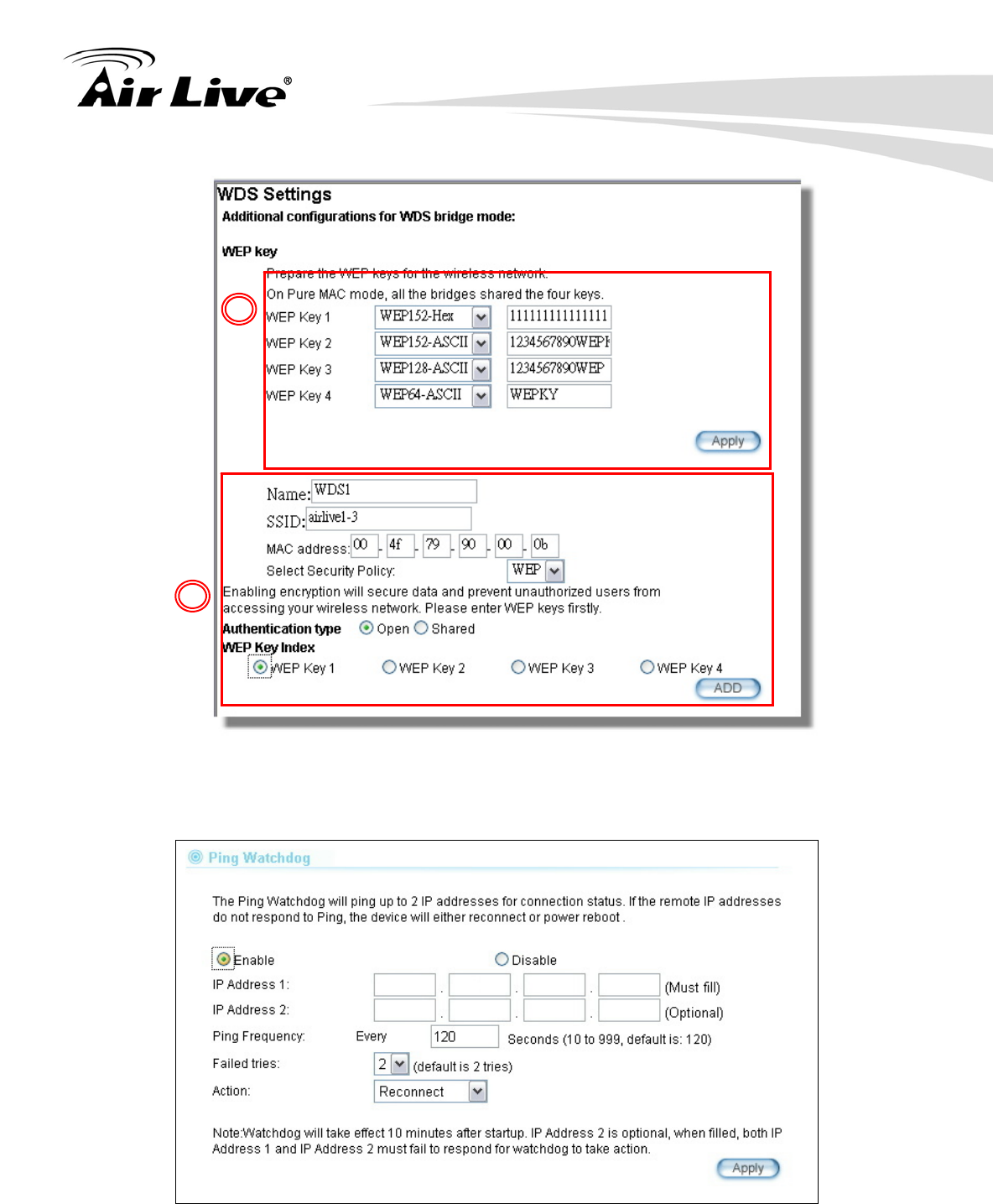
WDS Bridge 3 Settings
1. Enter the WEP Encryption Keys. In this example, we have 4 WEP keys with
WEP152-HEX, WEP152-ASCII, WEP128-ASCII, and WEP64-ASCII. Click on
“Apply” after entering the keys.
2. Adding the WDS Link to WDS Bridge 1
Name: WDS1
SSID: airlive1-3
MAC address: you should enter the MAC address of WDS Bridge 1:
00-4f-79-90-00-0b
Select Security Policy: Select “WEP” encryption. The AirMax5 will ask you to
select which key to use. You can select same key or different key for different
WDS link (however, both side of the same link must use the same key). In this
case, the Link between Bridge 1 and 3 is using Key1.
Click on “Add” to add the WDS Link.
9. Application Example2: Bridge Network
AirLive AIRMAX5 User’s Manual 136
4. Setup the PING watchdog. Please setup the PING watchdog according to graphic
below:
.
After the above settings, the 3 WDS bridges should connect properly. Be sure to set
the Distance parameter for long distance connection.
1
2
192 168 1 1
10. Application Example3: Routers and Repeater
137 AirLive AIRMAX5 User’s Manual
In this chapter, you will learn how to use Repeater mode and WISP Router mode in one
network example. In addition, some router settings such as how to setup virtual server will
also be demonstrated.
10.1 Application Environment
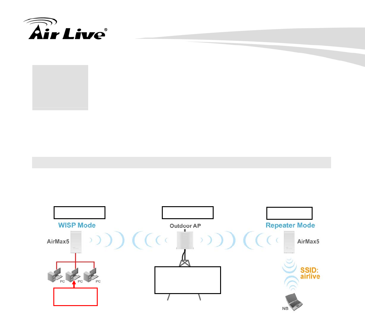
In the following application, the network is consisted of an Outdoor AP in the center, an
AirMax5 in WISP Router mode on the left, and a AirMax5 in Repeater mode on the right.
AirMax5 in WISP Mode
Make a wireless connection on the wireless WAN side to the Outdoor AP
Use Site Survey wizard to establish connection
Create a virtual server to LAN side FTP Server at 192.168.2.100
AirMax5 in Repeater Mode
Repeat the signal from Outdoor AP. On the AirMax5 settings the Remote AP’s SSID
will be “Outdoor AP”
On the wireless LAN side, the SSID will become “airlive”
10
1
0. Application Example 3:
Router and Repeater
SSID: OutdoorAP
Encryption:
WPA-PSK
192.168.1.100 192.168.1.254 192.168.1.1
FTP Server:
192.168.2.100
10. Application Example3: Routers and Repeater
AirLive AIRMAX5 User’s Manual 138
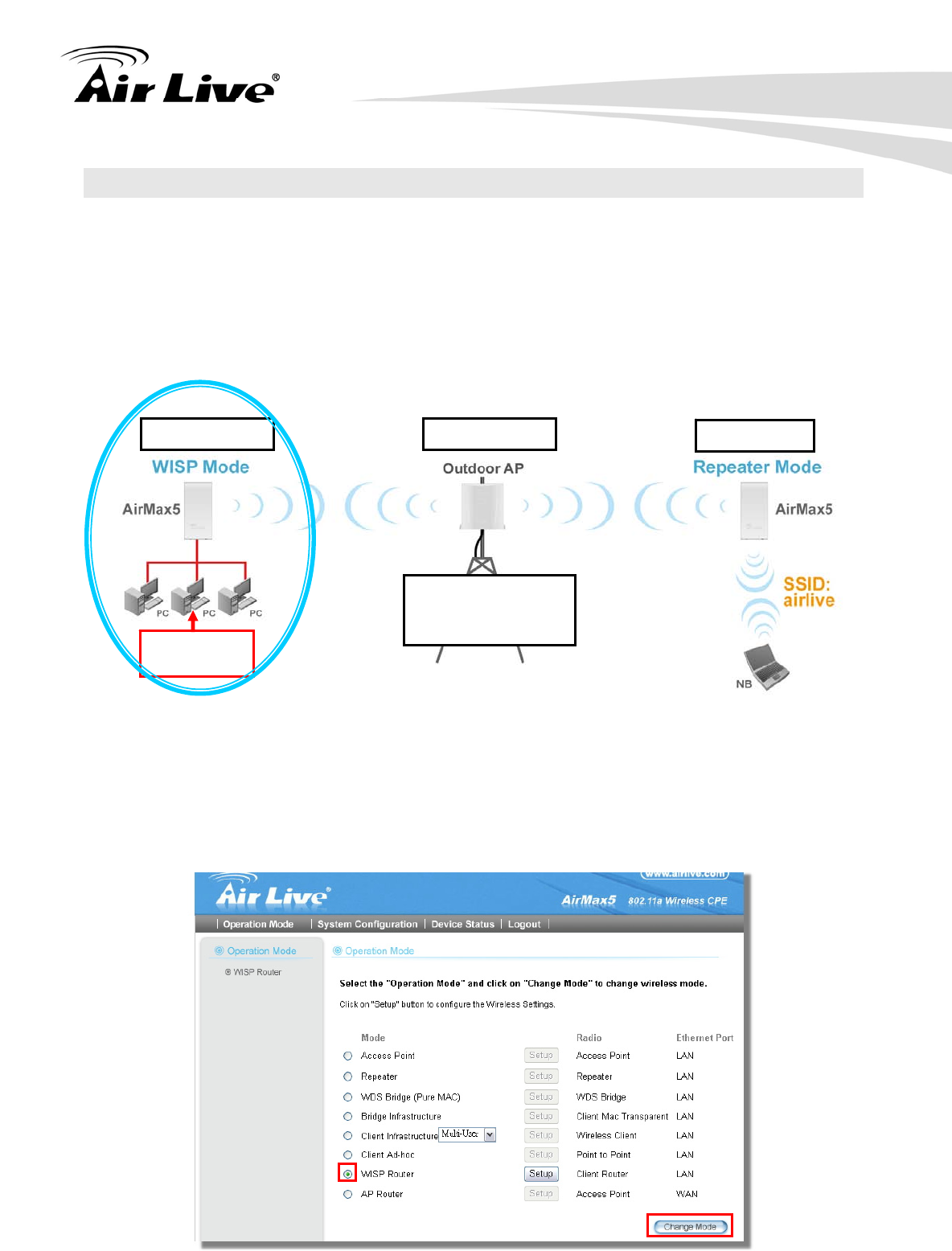
10.2 AirMax5 in WISP Router Mode
The following is the configuration procedure for the AirMax5 in WISP Router Mode:
Change the AirMax5 to WISP Router Mode
Change the LAN IP subnet to 192.168.2.X
Change the WAN port IP
Use Site Survey to connect with the Outdoor AP
Open Virtual Server to FTP server on the LAN side
10.2.1 WISP Router: Wireless Settings
Step 1 Go to “Operation Mode” menu. Select “WISP Router”, and then click on
“Change Mode” button.
SSID: OutdoorAP
Encryption:
WPA-PSK
192.168.1.100 192.168.1.254 192.168.1.1
FTP Server:
192.168.2.100
10. Application Example3: Routers and Repeater
139 AirLive AIRMAX5 User’s Manual
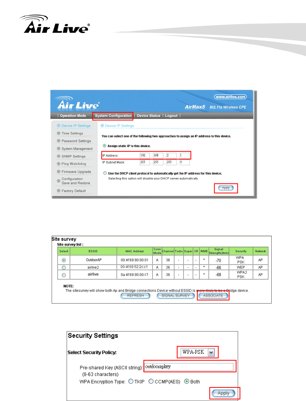
Step 2 Go to “System Configurations -> Device IP settings”. Change the LAN IP
address to “192.168.2.1”. Changing this IP address will also change the DHCP
IP range to 192.168.2.x subnet. Note: Please make sure your PC’s IP address
is also changed to 192.168.2.x subnet in order to configure the AirMax5.
Step 3 Go to “Operation Mode -> Setup” to enter the wireless settings. Select “Outdoor
AP” and click on the “Associate” button
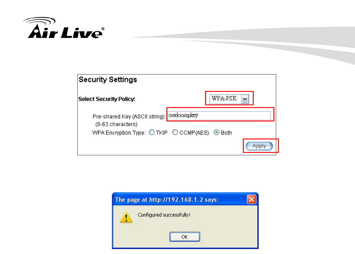
Step 4 AirMax5 will prompt you to enter the security policy. Select “WPA-PSK” and
enter “outdoorapkey” for the Pre-Shared Key.
10. Application Example3: Routers and Repeater
AirLive AIRMAX5 User’s Manual 140
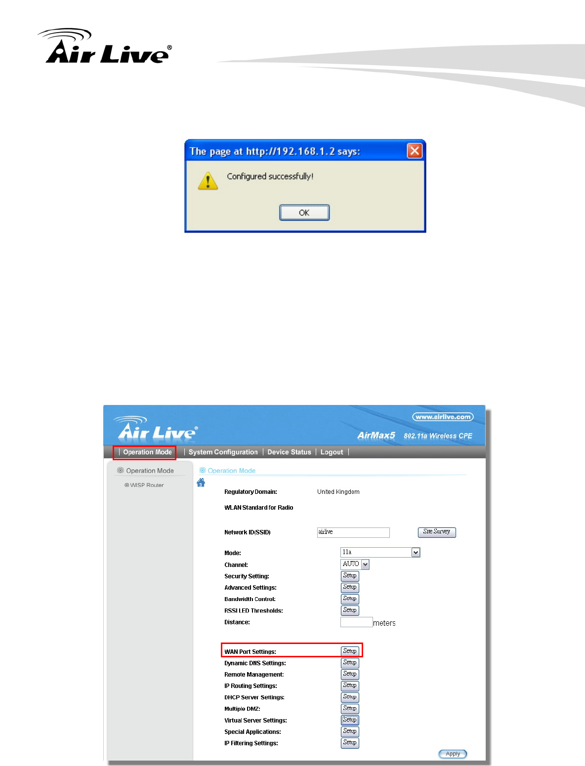
Step 5 Click on “Apply”. After a few seconds, the following screen will appear to show
successful connection.
10.2.2 WISP Router: WAN Port and Virtual Server
Objective:
1. Change WAN port’s IP address to 192.168.1.100
2. open a virtual server port to the FTP server at 192.168.2.100.
Step 1 Go to “Operation Mode” menu, click on “Setup” button. On the wireless settings
page, selecct “WAN port” button.
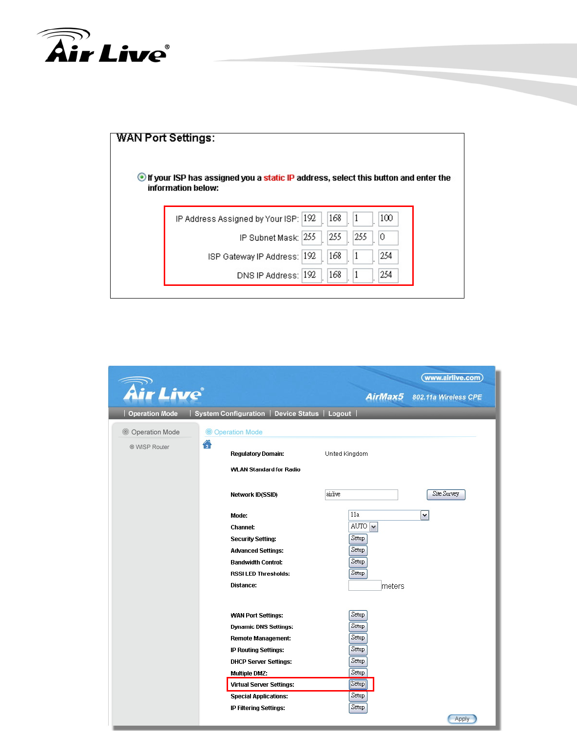
10. Application Example3: Routers and Repeater
141 AirLive AIRMAX5 User’s Manual
Step 2 On the WAN port setting pave, Enter the Static IP information as bellowed:
Step 3 Go to “Operation Mode” menu, click on “Setup” button. On the wireless settings
page, choose “Virtual Server” button.
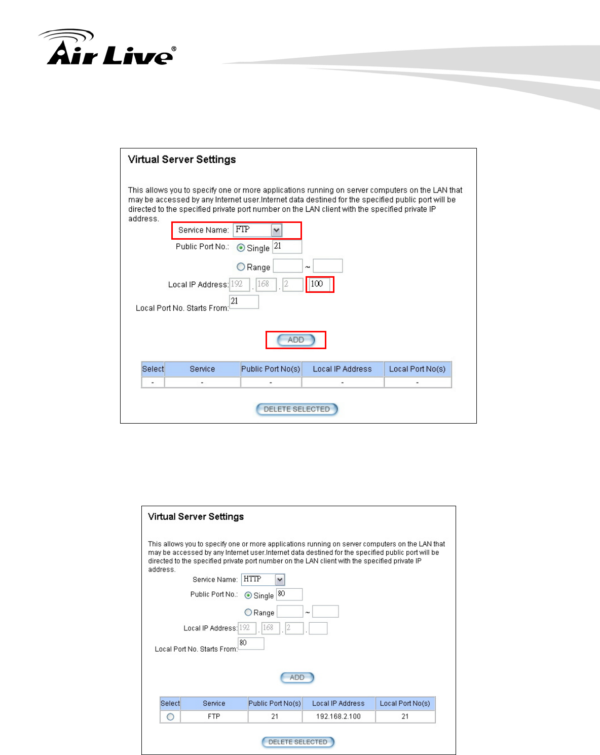
10. Application Example3: Routers and Repeater
AirLive AIRMAX5 User’s Manual 142
Step 4 Select “FTP” for Service Name. Enter 192.168.2.100 for the FTP server’s IP
address. Then click on “Add” to finish
Step 5 Once the virtual server is added, it will be displayed in the boxed area.
10. Application Example3: Routers and Repeater
143 AirLive AIRMAX5 User’s Manual
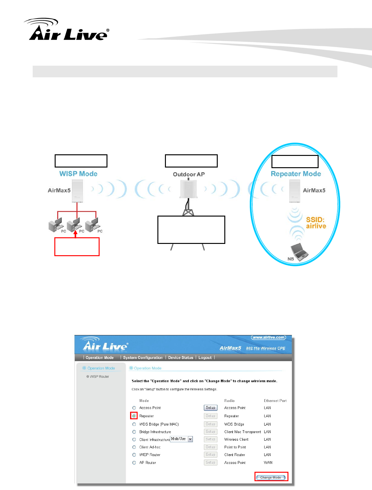
10.3 AirMax5 in Repeater Mode
The following is the configuration procedure for the AirMax5 in Repeater:
Change the AirMax5 to Repeater Mode
Use “Site Survey” function to find remote AP with SSID “OutdoorAP”, then establish
connection
The local wireless network’s SSID is airlive.
10.3.1 Repeater Router: Wireless Settings
Step 1 Go to “Operation Mode” menu. Select “Repeater”, and then click on “Change
Mode” button.
SSID: OutdoorAP
Encryption:
WPA-PSK
192.168.1.100 192.168.1.254 192.168.1.1
FTP Server:
192.168.2.100
10. Application Example3: Routers and Repeater
AirLive AIRMAX5 User’s Manual 144
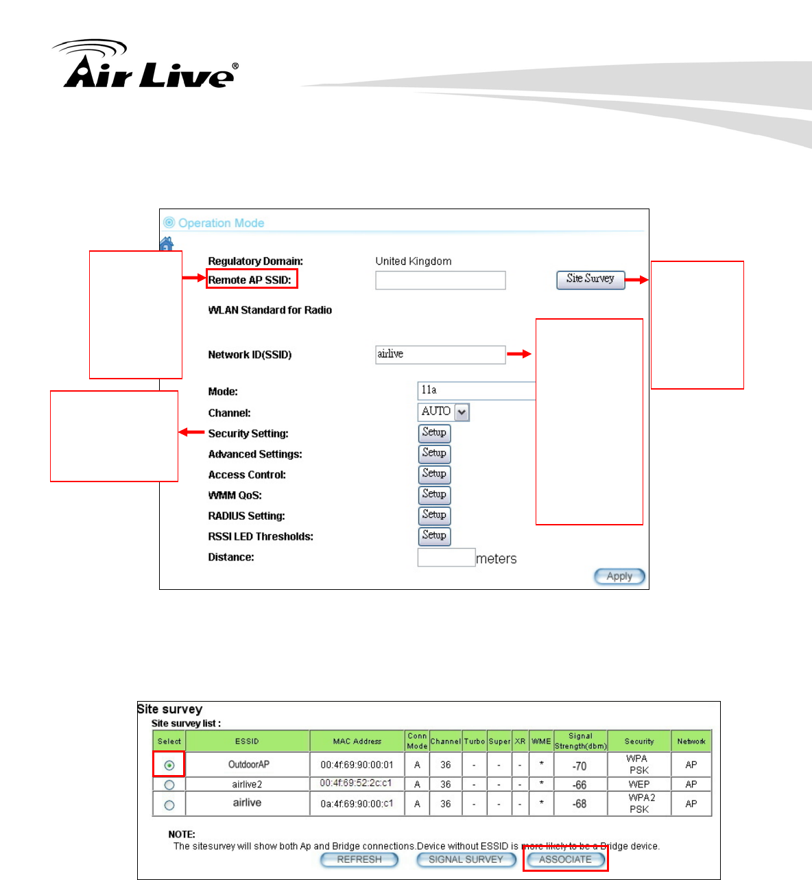
Step 2 Click on the “Setup” button and the wireless setting page will appear. Please
take a look at the description on the graphic below
Step 3 Click on Site Survey button, the following screen will appear. Choose
“OutdoorAP”, and then click on “Associate” button to connect.
Step 4 AirMax5 will prompt you to enter the security policy. Select “WPA-PSK” and
enter “outdoorapkey” for the Pre-Shared Key.
Enter the
SSID of the
remote AP
that you
want
AirMax5 to
repeat
Use Site
Survey
wizard to
find the
remote AP
and make
connection
Local wireless
LAN’s SSID.
This can be
the same or
different from
the remote
AP’s SSID.
In this
example,
please enter
airlive for
local SSID.
The wireless
security policy
must be the same
as the remote AP
10. Application Example3: Routers and Repeater
145 AirLive AIRMAX5 User’s Manual
Step 5 Click on “Apply”. After a few seconds, the following screen will appear to show
successful connection.
Now you should have established successful WISP Router and Repeater connections.
11. Emergency Firmware Recovery
AirLive AIRMAX5 User’s Manual 146
The AirMax5 features an Emergency Recovery function in the bootloader to recovery the
AP in case of a firmware crashed. When you can’t access the AirMax5, please first try to
repower the CPE or restore the settings to default. You should find the CPE at
192.168.1.1.
If it still can not solve the problem, you can try to recover the CPE using the method
described in this chapter. Do not power off the AirMax5 or your PC during process.
Please read through this chapter carefully before attempting to perform the upgrade. If the
AirMax5 is damaged by improper use of this procedure, it will void your warranty. It is
recommended to have your dealer or distributor performing this procedure.
11.1 How Emergency Upgrade Works
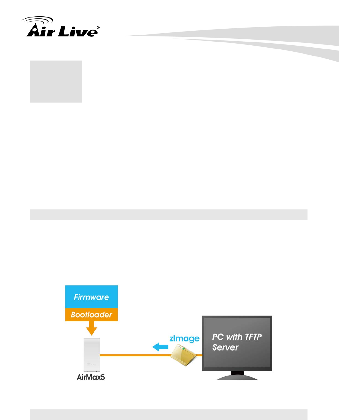
The AirMax5’s flash memory is divided into “firmware” and “bootloader” area. The
bootloader area will check if the AP’s firmware is crashed at each bootup. If it detects the
firmware is crashed, the AP will try to download the firmware file “zImage” from remote
TFTP server(with IP address 192.168.1.254) automatically. Therefore, you must prepare
a PC with TFTP server software before performing the upgrade procedure.
11.2 Emergency Upgrade Procedure
1. Set your PC’s IP address to 192.168.1.254 and connect your PC directly to the
AIRMAX5.
11 11. Emergency Firmware
Recovery
11. Emergency Firmware Recovery
147 AirLive AIRMAX5 User’s Manual
2. Set the PC as TFTP server, IP address of PC is 192.168.1.254, subnet mask is
255.255.255.0.
3. We recommend the freeware of tftp server, such as “tftpd32”.
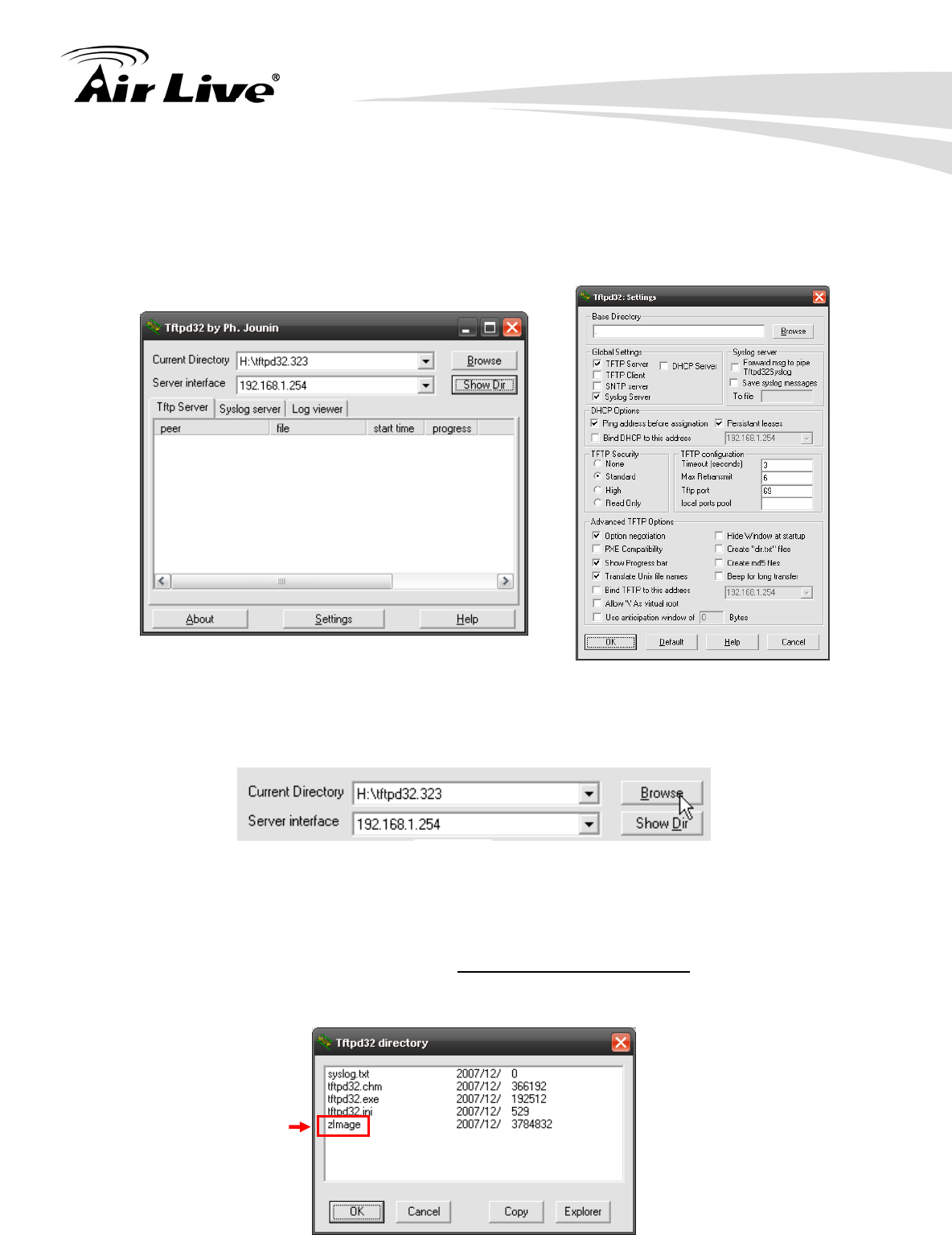
4. Run the TFTP server application.
Fig. tftpd32 application main window and setting window.
5. Assign the tftp folder in the tftp server. Click on “browse” the folder to select the
directory
Fig. tftpd32 application: Click on “browse” the folder to select the directory
6. Copy firmware file into the tftp server folder.
7. Rename this firmware file as “zImage” without file name extension. Please make
sure the letter case match exactly. To check if the file is available in the tftpd32 folder,
please click in tftpd32 main page “Show Dir”.
Fig. “Show Dir” to check available files in tftp server folder
11. Emergency Firmware Recovery
AirLive AIRMAX5 User’s Manual 148
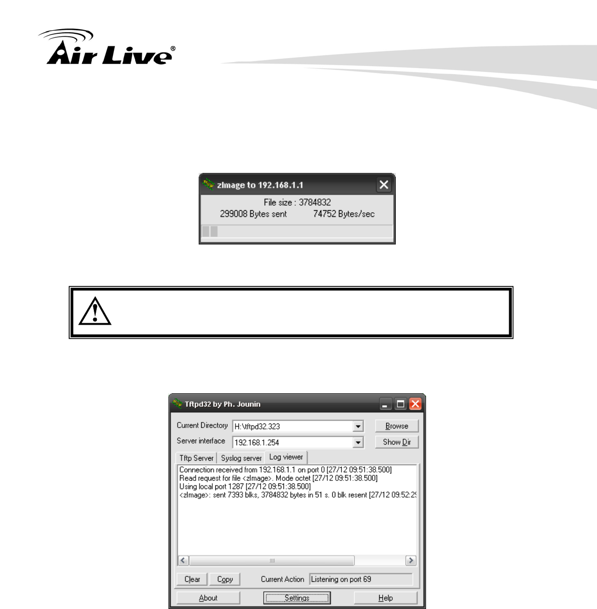
8. Power on the AIRMAX5 again. If firmware crashed, the device will scan the
192.168.1.254 for TFTP server and read the tftp upload file.
9. Wait for about 20 seconds, a pop-up window shows the firmware repair progress
screen.(Shown as Fig. 3)
Fig.. Tftpd32 show at the beginning of firmware repair progress.
Do not power off the PC or the AirMax5 during this process! Any
disconnection or interruption can damage the AirMax5 permanently.
10. Device will continue proceeding. If you click on the “log viewer” of tftpd32, you can see
progress of work shown as Fig. 4.
Fig. 4 Repair progress shown in tftpd32 syslog Log viewer
11. Please wait for 5 minutes for the device to reboot. When finish rebooting, the wireless
LED will be on. The device can then be accessed again at 192.168.1.1. If the
AIRMAX5’s not accessible after 5 minutes, please power reboot the AIRMAX5.
12. Open your web browser and type “192.168.1.1” to confirm the AIRMAX5 is restored.
12. Frequent Asked Questions
149 AirLive AIRMAX5 User’s Manual
In this chapter, we will address some frequent asked questions about AirMax5
Question: I forgot my password or the IP address of AirMax5.
Answer: Please restore your settings to default by press the reset button for more than
5 seconds. You should be able to find your AirMax5 at 192.168.1.1 with
password “airlive”.
====================================================================
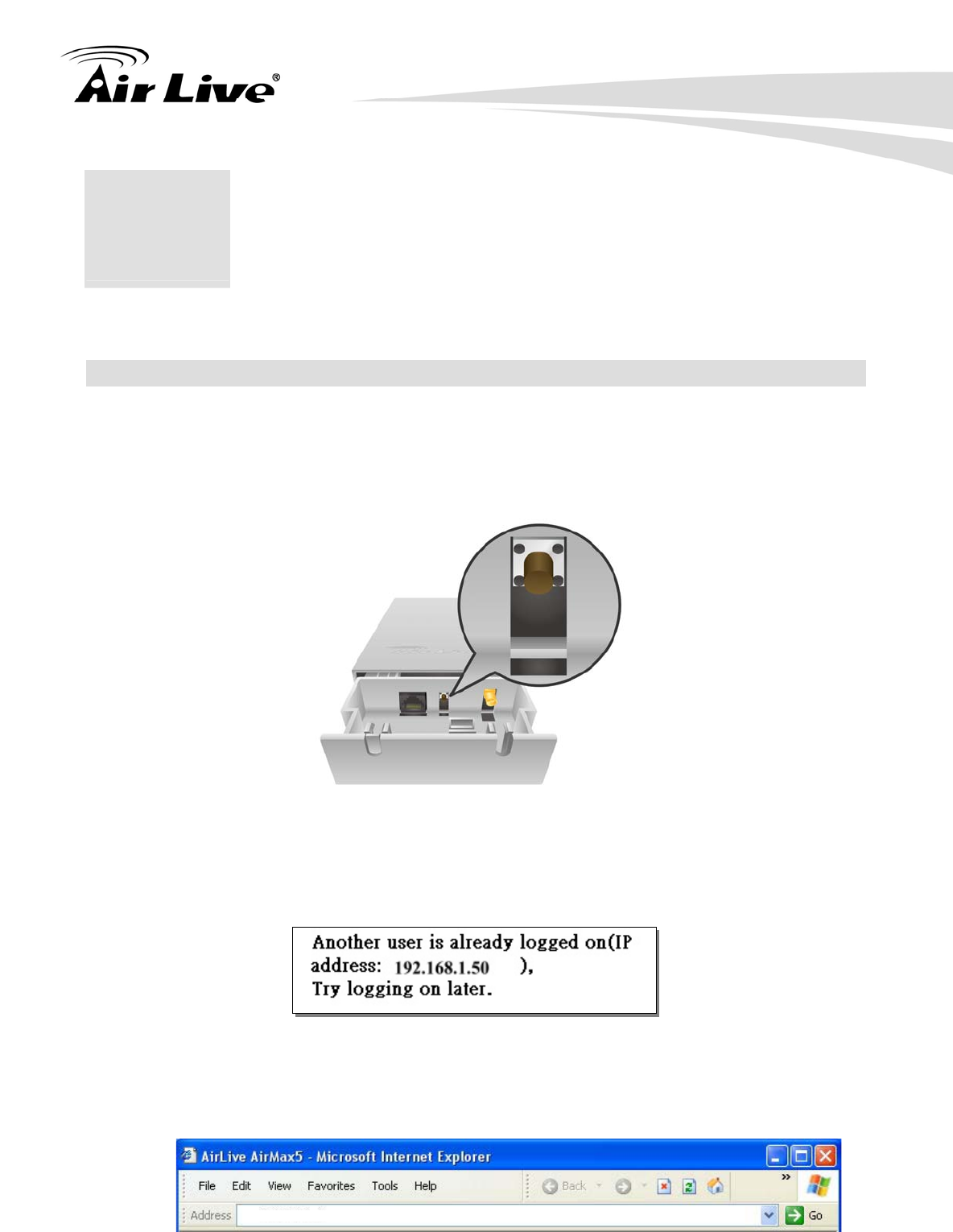
Question: When I try to configure AirMax5, the following message pop-up saying there is
already someone login in to the AirMax5
Answer: The AirMax5 firmware after 1.00e12 version already removes this restriction.
However, if you do not wish to upgrade firmware; you can force another
administrator to logout by typing “login.asp” on your browser. Then key-in the
password again to enter the management interface.
12 12. Frequent Asked
Questions
https://192.168.1.1/login.asp

12. Frequent Asked Questions
AirLive AIRMAX5 User’s Manual 150
====================================================================
Question: I heard AirMax5 can limit the bandwidth of BitTorrent and eDonkey traffic. But
I don’t see the option on the Bandwidth Control.
Answer: The option to limit bandwidth by application or port is available only on WISP
router and AP Router modes.
====================================================================
Question: Where can I purchase the optional metal Mounting Kit?
Answer: The part number for the mounting kit is “WMK-AIRMAX”. Please ask your
authorized AirLive distributor for availability.
====================================================================
Question: How can I make connection with Mikrotik AP?
Answer: The AirMax5 can connect with Mirkrotik AP using Bridge Infrastructure
Mode(Supports WEP, WPA-PSK, WPA2-PSK), Client Infrastructure mode
(support WEP, WPA-PSK, WPA2-PSK) and WDS Bridge mode (support
WEP). If using Bridge Infrastructure mode (WDS station), please enable
“WDS Dynamic” on Mikrotik’s “AP Bridge” mode. If using WEP, please
choose “Static Key Required” on the Mirkrotik setting. For step-by-step
example, please visit AirLive.com’s support page at:
http://www.airlive.com/support/support_1.jsp. Type “airmax5” at the support
search.
====================================================================
Question: When I plug in the POE cable and power adapter, the AirMax5’s power LED is
not on?
Answer: Please make sure you have connected the PoE cable to the correct port on
the DC injector. Moreover, you should use an Ethernet cable with 4 twisted
pairs (CAT5 or better) for POE cable.
====================================================================
12. Frequent Asked Questions
151 AirLive AIRMAX5 User’s Manual
Question: I tried the Emergency Upgrade procedure. But it doesn’t work, why?
Answer: Please make sure the firmware file is renamed to “zImage” without any file
extension. The file name has to match exactly with the big capital “I”.
====================================================================
Question: Why can’t I receive any signal from AirMax5’s built in antenna?
Answer: The AirMax5’s built-in antenna is a patch antenna that sends and receive
signal in the forward direction of the CPE with 30 degree angle vertically and
horizontally. Please see diagram below:
====================================================================
Question: Where is the signal survey function that displays the RSSI value continuously?
Answer: The “Signal Survey” function is inside the Site Survey function. You can
access from “Operation Mode -> Setup -> Site Survey” menu.

12. Frequent Asked Questions
AirLive AIRMAX5 User’s Manual 152
====================================================================
Question: When do I use Per-User Bandwidth Control by IP, MAC, or IP segment?
Answer: In general, IP address control limits the devices on the end node (i.e. PC and
WISP router). MAC address control can limit the traffic of a AP/CPE in
wireless client mmode.
IP address: When you want to limit the bandwidth of a single notebook
computer, PC, or WISP router.
MAC address: When you want to limit the bandwidth of a remote
AP/CPE in Client mode. For example, another AirMax5 in client mode
IP Segment:: When you want to limit the bandwidth of an entire IP range.
For example, all the PCs using the DHCP server to get IP addresses.
====================================================================
Question: When I use “Site Survey”, why does the RSSI LED goes off?
Answer: When you click on the Site Survey, the AirMax5 thinks you are trying to
choose a new network to associate. Therefore, it will disconnect from
current connection and wait until you establish a new connection. If you
require seeing the wireless link quality after connection is established, please go to
“Device Status->Wireless” menu to see the “RSSI” value.
====================================================================

13. Specifications
153 AirLive AIRMAX5 User’s Manual
The specification of AirMax5 is subject to change without notice. Please use the
information with caution.
13.1 Hardware Features
13.1.1 General Hardware Feature
Atheros AR-2313 + AR-5112 chipset
802.11a/Super A/Turbo-A mode support (Atheros Proprietary)
8MB Flash, 32MB SDRAM
RoHS compliant
One 10/100 Mbps Ethernet Port / PoE Port with Auto MDI/MDI-X support
12V Passive PoE (accept up to 24V)
802.11h compatible
DFS and DFSII compliant
24dBm Transmit Output power
Rain and splash proof housing
4 LED indicators with RSSI LED function
Optional Metal Wall / Pole Mount Kit
13.1.2 Antenna
Integrated 14 dBi patch directional antenna
Vertical, Horizontal, Diversity Polarizations
Software switchable between polarization
H-Plane Coverage Angle: 30 degree in the forward direction
E-Plane Coverage Angle: 30 degree in the forward direction
13.1.3 Power Supply
Power Adapter Voltage : input 100~240Vac/50~60Hz , output 12V/1A
Advance Passive PoE (Accept 12 to 24 volts)
POE Adapter, DC Injector provided
13 13. Specifications

13. Specifications
AirLive AIRMAX5 User’s Manual 154
13.1.4 Dimension and Weight
Dimension: 210 x 100 x 32 mm
Package Weight: 750g
13.2 Radio Specifications
13.2.1 Frequency Band
5.15 to 5.25GHz: U-NII Low and ETSI Band1
5.25 to 5.35GHz: U-NII Mid and ETSI Band2
5.47 to 5.725GHz: U-NII World Wide and ETSI Band3
5.745 to 5.825GHz, U-NII Upper Band
13.2.2 Rate and Modulation
Data Rate : 6, 9, 12, 18, 24, 36, 48, 54Mbps
Modulation: Orthogonal Frequency Division Multiplexing (OFDM)
13.2.3 TX Output Power
54 Mbps @ 21dBm
48 Mbps @ 22dBm
36 Mbps @ 23dBm
6, 9, 12, 18, 24 Mbps @ 23 dBm
13.2.4 Receiver Sensitivity
6Mbps @ -90 dBm
9Mbps @ -89 dBm
12Mbps @ -88 dBm
18Mbps @ -86 dBm
24Mbps @ -82 dBm

13. Specifications
155 AirLive AIRMAX5 User’s Manual
36Mbps @ -79 dBm
48Mbps @ -73dBm
54Mbps @ -71dBm
13.2.5 Supported WLAN Mode
11a mode
SuperA without Turbo
SuperA with Dynamic Turbo
SuperA with Static Turbo
13.3 Software Feature
13.3.1 Operation Mode
Access Point Mode (AP mode)
Client Infrastructure Mode
Client Adhoc Mode
WDS Bridge Mode
Bridge Infrastructure Mode
Repeater Mode
WISP Router Mode
AP Router Mode
13.3.2 Management Interface
Web HTTP
Secured Web (HTTPS)
Telnet (CLI)
SSH/SSH2 (Secured Shell)
SNMP v1/v2 Support
SNMP Read/Write Community String
SNMP Trap support
MIB and MIB II Support
Ether-like MIB

13. Specifications
AirLive AIRMAX5 User’s Manual 156
IEEE802dot11 MIB
Private MIB
13.3.3 Channel Width (Rate Mode)
Full: 20 MHz (default)
Half: 10 MHz
Quarter: 5 MHz
13.3.4 Advance Functions
Site Survey with RSSI Signal Survey
Total Bandwidth and Per-User Bandwidth Management
Noise Immunity
Multiple SSID and Tag VLAN
QoS (802.11e WMM)
Wi-Fi, WPA compatible interoperability
WPA with PSK/TKIP/AES support ,WPA2 support
Privacy Separator support
Support adjustable output power
152-bit WEP support (Atheros Proprietary)
ACK Timeout Adjustment
Bootloader Protection and Emergency Firmware Upload Code
Radius Supported
Firmware upgrade and configuration backup via Web

14. Wireless Network Glossary
157 AirLive AIRMAX5 User’s Manual
The wireless network glossary contains explanation or information about common terms
used in wireless networking products. Some of information in this glossary might be
outdated, please use with caution.
802.11a
An IEEE specification for wireless networking that operates in the 5 GHz frequency range
(5.15 GHz to 5.850 GHz) with a maximum of 54 Mbps data transfer rate. The 5 GHz
frequency band is not as crowded as the 2.4 GHz band. In addition, the 802.11a have 12
non-overlapping channels, comparing to 802.11b/g's 3 non-overlapping channels. This
means the possibility to build larger non-interfering networks. However, the 802.11a deliver
shorter distance at the same output power when comparing to 802.11g.
802.3ad
802.3ad is an IEEE standard for bonding or aggregating multiple Ethernet ports into one
virtual port (also known as trunking) to increase the bandwidth.
802.3af
This is the PoE (Power over Ethernet) standard by IEEE committee. 803.af uses 48V
POE standard that can deliver up to 100 meter distance over Ethernet cable.
802.11b
International standard for wireless networking that operates in the 2.4 GHz frequency band
(2.4 GHz to 2.4835 GHz) and provides a throughput up to 11 Mbps.
802.1d STP
Spanning Tree Protocol. It is an algorithm to prevent network from forming. The STP
protocol allows net work to provide a redundant link in the event of a link failure. It is
advise to turn on this option for multi-link bridge network.
14 14. Wireless Network
Glossary

14. Wireless Network Glossary
AirLive AIRMAX5 User’s Manual 158
802.11d
Also known as “Global Roaming”. 802.11d is a standard for use in countries where
systems using other standards in the 802.11 family are not allowed to operate.
802.11e
The IEEE QoS standard for prioritizing traffic of the VoIP and multimedia applications.
The WMM is based on a subset of the 802.11e.
802.11g
A standard provides a throughput up to 54 Mbps using OFDM technology. It also
operates in the 2.4 GHz frequency band as 802.11b. 802.11g devices are backward
compatible with 802.11b devices.
802.11h
This IEEE standard define the TPC (transmission power control) and DFS(dynamic
frequency selection) required to operate WiFi devices in 5GHz for EU.
802.11i
The IEEE standard for wireless security. 802.11i standard includes TKIP, CCMP, and
AES encryption to improve wireless security. It is also know as WPA2.
802.1Q Tag VLAN
In 802.1Q VLAN, the VLAN information is written into the Ethernet packet itself. Each
packet carries a VLAN ID(called Tag) as it traveled across the network. Therefore, the
VLAN configuration can be configured across multiple switches. In 802.1Q spec, possible
4096 VLAN ID can be created. Although for some devices, they can only view in frames
of 256 ID at a time.
802.1x
802.1x is a security standard for wired and wireless LANs. In the 802.1x parlance, there are
usually supplicants (client), authenticator (switch or AP), and authentication server (radius
server) in the network. When a supplicants request a service, the authenticator will pass
the request and wait for the authentication server to grant access and register accounting.
The 802.1x is the most widely used method of authentication by WISP.

14. Wireless Network Glossary
159 AirLive AIRMAX5 User’s Manual
Adhoc
A Peer-to-Peer wireless network. An Adhoc wireless network do not use wireless AP or
router as the central hub of the network. Instead, wireless client are connected directly to
each other. The disadvantage of Adhoc network is the lack of wired interface to Internet
connections. It is not recommended for network more than 2 nodes.
Access Point (AP)
The central hub of a wireless LAN network. Access Points have one or more Ethernet
ports that can connect devices (such as Internet connection) for sharing. Multi-function
Access Point can also function as an Ethernet client, wireless bridge, or repeat signals from
other AP. Access Points typically have more wireless functions comparing to wireless
routers.
ACK Timeout
Acknowledgement Timeout Windows. When a packet is sent out from one wireless station
to the other, it will waits for an Acknowledgement frame from the remote station. The
station will only wait for a certain amount of time, this time is called the ACK timeout. If the
ACK is NOT received within that timeout period then the packet will be re-transmitted
resulting in reduced throughput. If the ACK setting is too high then throughput will be lost
due to waiting for the Ack Window to timeout on lost packets. If the ACK setting is too low
then the ACK window will have expired and the returning packet will be dropped, greatly
lowering throughput. By having the ability to adjust the ACK setting we can effectively
optimize the throughput over long distance links. This is especially true for 802.11a and
802.11g networks. Setting the correct ACK timeout value need to consider 3 factors:
distance, AP response time, and interference. The AirMax5 provide ACK adjustment
capability in form of either distance or direct input. When you enter the distance
parameter, the AirMax5 will automatically calculate the correct ACK timeout value.
Bandwidth Management
Bandwidth Management controls the transmission speed of a port, user, IP address, and
application. Router can use bandwidth control to limit the Internet connection speed of
individual IP or Application. It can also guarantee the speed of certain special application
or privileged IP address - a crucial feature of QoS (Quality of Service) function. The
AirMax5’s features both “Per-user Bandwidth Control” and “Total Bandwidth Control”.
“Per-user Bandwidth Control” allow administrator to define the maximum bandwidth of each
user by IP, IP Group, or MAC address. Total Bandwidth define the maximum bandwidth of
wireless or Ethernet interface.

14. Wireless Network Glossary
AirLive AIRMAX5 User’s Manual 160
Bootloader
Bootloader is the under layering program that will start at the power-up before the device
loads firmware. It is similar to BIOS on a personal computer. When a firmware crashed,
you might be able to recover your device from bootloader.
Bridge
A product that connects 2 different networks that uses the same protocol. Wireless
bridges are commonly used to link network across remote buildings. For wireless
application, there are 2 types of Bridges. WDS Bridge can be used in Point-to-Point or
Point-to-Multipoint topology. Bridge Infrastructure works with AP mode to form a star
topology.
Cable and Connector Loss: During wireless design and deployment, it is important to
factor in the cable and connector loss. Cable and connector loss will reduce the output
power and receiver sensitivity of the radio at connector end. The longer the cable length is,
the more the cable loss. Cable loss should be subtracted from the total output power
during distance calculation. For example, if the cable and connector loss is 3dBm and the
output power is 20dBm; the output power at the cable end is only 17dBm.
Client
Client means a network device or utility that receives service from host or server. A client
device means end user device such as wireless cards or wireless CPE.
CPE Devices
CPE stands for Customer Premises Equipment. A CPE is a device installed on the end
user's side to receive network services. For example, on an ADSL network, the ADSL
modem/router on the subscriber's home is the CPE device. Wireless CPE means a
complete Wireless (usually an AP with built-in Antenna) that receive wireless broadband
access from the WISP. The opposite of CPE is CO.
CTS
Clear To Send. A signal sent by a device to indicate that it is ready to receive data.
DDNS
Dynamic Domain Name System. An algorithm that allows the use of dynamic IP address

14. Wireless Network Glossary
161 AirLive AIRMAX5 User’s Manual
for hosting Internet Server. A DDNS service provides each user account with a domain
name. A router with DDNS capability has a built-in DDNS client that updates the IP
address information to DDNS service provider whenever there is a change. Therefore,
users can build website or other Internet servers even if they don't have fixed IP
connection.
DHCP
Dynamic Hosting Configuration Protocol. A protocol that enables a server to dynamically
assign IP addresses. When DHCP is used, whenever a computer logs onto the network, it
automatically gets an IP address assigned to it by DHCP server. A DHCP server can
either be a designated PC on the network or another network device, such as a router.
DMZ
Demilitarized Zone. When a router opens a DMZ port to an internal network device, it opens
all the TCP/UDP service ports to this particular device. The feature is used commonly for
setting up H.323 VoIP or Multi-Media servers.
DNS
A program that translates URLs to IP addresses by accessing a database maintained on a
collection of Internet servers.
Domain Name
The unique name that identifies an Internet site. Domain Names always have 2 or more
parts, separated by dots. In www.airlive.com, the "airlive.com" is the doman name.
DoS Attack
Denial of Service. A type of network attack that floods the network with useless traffic.
Many DoS attacks, such as the Ping of Death and Teardrop attacks, exploit limitations in
the TCP/IP protocols.
Encryption
Encoding data to prevent it from being read by unauthorized people. The common
wireless encryption schemes are WEP, WPA, and WPA2.

14. Wireless Network Glossary
AirLive AIRMAX5 User’s Manual 162
ESSID (SSID)
The identification name of an 802.11 wireless network. Since wireless network has no
physical boundary liked wired Ethernet network, wireless LAN needs an identifier to
distinguish one network from the other. Wireless clients must know the SSID in order to
associate with a WLAN network. Hide SSID feature disable SSID broadcast,
so users must know the correct SSID in order to join a wireless network.
Firewall
A system that secures a network and prevents access by unauthorized users. Firewalls can
be software, router, or gateway. Firewalls can prevent unrestricted access into a network,
as well as restricting data from flowing out of a network.
Firmware
The program that runs inside embedded device such as router or AP. Many network
devices are firmware upgradeable through web interface or utility program.
FTP
File Transfer Protocol. A standard protocol for sending files between computers over a
TCP/IP network and the Internet.
Fragment Threshold
Frame Size larger than this will be divided into smaller fragment. If there are interferences
in your area, lower this value can improve the performance. If there are not, keep this
parameter at higher value. The default size is 2346. You can try 1500, 1000, or 500
when there are interference around your network.
Full Duplex
The ability of a networking device to receive and transmit data simultaneously. In wireless
environment, this is usually done with 2 or more radios doing load balancing.
Gateway
In the global Internet network, the gateways are core routers that connect networks in
different IP subnet together. In a LAN environment with an IP sharing router, the gateway
is the router. In an office environment, gateway typically is a multi-function device that
integrates NAT, firewall, bandwidth management, and other security functions.

14. Wireless Network Glossary
163 AirLive AIRMAX5 User’s Manual
Hotspot
A place where you can access Wi-Fi service. The term hotspot has two meanings in
wireless deployment. One is the wireless infrastructure deployment, the other is the
Internet access billing system. In a hotspot system, a service provider typically need an
authentication and account system for billing purposes, and a wireless AP network to
provide access for customers.
IGMP Snooping
Internet Group Management Protocol (IGMP) is a Layer 3 protocol to report IP multicast
memberships to neighboring multicast switches and routers. IGMP snooping is a feature
that allows an Ethernet switch to "listen in" on the IGMP conversation between hosts and
routers. A switch support IGMP snooping has the possibility to avoid multicast traffic being
treated as broadcast traffic; therefore, reducing the overall traffic on the network.
Infrastructure Mode
A wireless network that is built around one or more access points to provide wireless clients
access to wired LAN / Internet service. The opposite of Infrastructure mode is Adhoc
mode.
IP address
IP (Internet Protocol) is a layer-3 network protocol that is the basis of all Internet
communication. An IP address is 32-bit number that identifies each sender or receiver of
information that is sent across the Internet. An IP address has two parts: an identifier of a
particular network on the Internet and an identifier of the particular device (which can be a
server or a workstation) within that network. The new IPv6 specification supports 128-bit
IP address format.
IPsec
IP Security. A set of protocols developed by the IETF to support secure exchange of
packets at the IP layer. IPsec has been deployed widely to implement Virtual Private
Networks (VPNs). IPsec supports two encryption modes: Transport and Tunnel.
Transport mode encrypts only the data of each packet, but leaves the header untouched.
The more secure Tunnel mode encrypts both the header and the payload. On the receiving
side, an IPSec-compliant device decrypts each packet.
LACP (802.3ad) Trunking

14. Wireless Network Glossary
AirLive AIRMAX5 User’s Manual 164
The 802.3ad Link Aggregation standard defines how to combine the several Ethernet ports
into one high-bandwidth port to increase the transmission speed. It is also known as port
trunking. Both device must set the trunking feature to work.
MAC
Media Access Control. MAC address provides layer-2 identification for Networking Devices.
Each Ethernet device has its own unique address. The first 6 digits are unique for each
manufacturer. When a network device have MAC access control feature, only the devices
with the approved MAC address can connect with the network.
Mbps
Megabits Per Second. One million bits per second; a unit of measurement for data
transmission
MESH
Mesh is an outdoor wireless technology that uses Spanning Tree Protocol (STP) and
Wireless Distribution system to achieve self-forming, self-healing, and self-configuring
outdoor network. MESH network are able to take the shortest path to a destination that
does not have to be in the line of site.
MIMO
Multi In Multi Out. A Smart Antenna technology designed to increase the coverage and
performance of a WLAN network. In a MIMO device, 2 or more antennas are used to
increase the receiver sensitivity and to focus available power at intended Rx.
NAT
Network Address Translation. A network algorithm used by Routers to enables several
PCs to share single IP address provided by the ISP. The IP that a router gets from the
ISP side is called Real IP, the IP assigned to PC under the NAT environment is called
Private IP.
Node
A network connection end point, typically a computer.

14. Wireless Network Glossary
165 AirLive AIRMAX5 User’s Manual
Packet
A unit of data sent over a network.
Passphrase
Used much like a password, a passphrase simplifies the WEP encryption process by
automatically generating the WEP encryption keys for the company products.
POE
Power over Ethernet. A standard to deliver both power and data through one single
Ethernet cable (UTP/STP). It allows network device to be installed far away from power
ource. A POE system typically compose of 2 main component: DC Injector (Base Unit)
and Splitter(Terminal Unit). The DC injector combines the power and data, and the splitter
separates the data and power back. A PoE Access Point or CPE has the splitter built-in to
the device. The IEEE 802.3af is a POE spec that uses 48 volt to deliver power up to 100
meter distance.
Port
This word has 2 different meaning for networking.
z The hardware connection point on a computer or networking device used for plugging
in a cable or an adapter.
z The virtual connection point through which a computer uses a specific application on a
server.
PPPoE
Point-to- Point Protocol over Ethernet. PPPoE relies on two widely accepted standards:
PPP and Ethernet. PPPoE is a specification for connecting the users on an Ethernet to the
Internet through a common broadband medium, such as a single DSL line, wireless device
or cable modem.
PPTP
Point-to-Point Tunneling Protocol: A VPN protocol developed by PPTP Forum. With
PPTP, users can dial in to their corporate network via the Internet. If users require data
encryption when using the Windows PPTP client, the remote VPN server must support
MPPE (Microsoft Point-To-Point Encryption Protocol) encryption. PPTP is also used by
some ISP for user authentication, particularly when pairing with legacy Alcatel / Thomson
ADSL modem.

14. Wireless Network Glossary
AirLive AIRMAX5 User’s Manual 166
Preamble Type
Preamble are sent with each wireless packet transmit for transmission status. Use the
long preamble type for better compatibility. Use the short preamble type for better
performance
Rate Control
Ethernet switches' function to control the upstream and downstream speed of an individual
port. Rate Control management uses "Flow Control" to limit the speed of a port.
Therefore, the Ethernet adapter must also have the flow control enabled. One way to
force the adapter's flow control on is to set a port to half-duplex mode.
RADIUS
Remote Authentication Dial-In User Service. An authentication and accounting system
used by many Internet Service Providers (ISPs). When you dial in to the ISP, you must
enter your username and password. This information is passed to a RADIUS server, which
checks that the information is correct, and then authorizes access to the ISP system.
Radius typically uses port 1812 and port 1813 for authentication and accounting port.
Though not an official standard, the RADIUS specification is maintained by a working group
of the IETF.
Receiver Sensitivity
Receiver sensitivity means how sensitive is the radio for receiving signal. In general; the
slower the transmission speed, the more sensitive the radio is. The unit for Receiver
Sensitivity is in dB; the lower the absolute value is, the higher the signal strength. For
example, -50dB is higher than -80dB.
RJ-45
Standard connectors for Twisted Pair copper cable used in Ethernet networks. Although
they look similar to standard RJ-11 telephone connectors, RJ-45 connectors can have up to
eight wires, whereas telephone connectors have only four.
Router
An IP sharing router is a device that allows multiple PCs to share one single broadband
connection using NAT technology. A wireless router is a device that combines the

14. Wireless Network Glossary
167 AirLive AIRMAX5 User’s Manual
functions of wireless Access Point and the IP sharing router.
RSSI
Receiver Sensitivity Index. RSSI is a value to show the Receiver Sensitivity of the remote
wireless device. In general, remote APs with stronger signal will display higher RSSI
values. For RSSI value, the smaller the absolute value is, the stronger the signal. For
example, “-50db” has stronger signal than “-80dB”. For outdoor connection, signal
stronger than -60dB is considered as a good connection.
RTS
Request To Send. A packet sent when a computer has data to transmit. The computer will
wait for a CTS (Clear To Send) message before sending data.
RTS Threshold
RTS (Request to Send). The RTS/CTS(clear to send) packet will be send before a frame
if the packet frame is larger than this value. Lower this value can improve the
performance if there are many clients in your network. You can try 1500, 1000 or 500
when there are many clients in your AP’s network.
SNMP
Simple Network Management Protocol. A set of protocols for managing complex
networks. The SNMP network contains 3 key elements: managed devices, agents, and
network-management systems (NMSs). Managed devices are network devices that
content SNMP agents. SNMP agents are programs that reside SNMP capable device's
firmware to provide SNMP configuration service. The NMS typically is a PC based
software such as HP Openview that can view and manage SNMP network device remotely.
SSH
Developed by SSH Communications Security Ltd., Secure Shell is a program to log into
another computer over a network, to execute commands in a remote machine, and to move
files from one machine to another. It provides strong authentication and secure
communications over insecure channels. It is a replacement for rlogin, rsh, rcp, and rdist.
SSL
Secure Sockets Layer. It is a popular encryption scheme used by many online retail and
banking sites to protect the financial integrity of transactions. When an SSL session

14. Wireless Network Glossary
AirLive AIRMAX5 User’s Manual 168
begins, the server sends its public key to the browser. The browser then sends a randomly
generated secret key back to the server in order to have a secret key exchange for that
session. SSL VPN is also known as Web VPN. The HTTPS and SSH management
interface use SSL for data encryption.
Subnet Mask
An address code mask that determines the size of the network. An IP subnet are
determined by performing a BIT-wise AND operation between the IP address and the
subnet mask. By changing the subnet mask, you can change the scope and size of a
network.
Subnetwork or Subnet
Found in larger networks, these smaller networks are used to simplify addressing between
numerous computers. Subnets connect to the central network through a router, hub or
gateway. Each individual wireless LAN will probably use the same subnet for all the local
computers it talks to.
Super A
Super A is an Atheros proprietary turbo mode to increase speed over standard 802.11a
mode. It adds Bursting and Compression to increase the speed. If you live in countries
that prohibit the channel binding technology (i.e. Europe), you should choose “Super-A
without Turbo) if you need more speed than 11a mode
TCP
A layer-4 protocol used along with the IP to send data between computers over the Internet.
While IP takes care of handling the actual delivery of the data, TCP takes care of keeping
track of the packets that a message is divided into for efficient routing through
the Internet.
Turbo A
Turbo A is an Atheros proprietary turbo mode to increase speed over standard 802.11a
mode. It uses channel binding technology to increase speed. There are 2 types of Turbo
A modes: Dynamic Turbo and Static Turbo. In Dynamic Turbo, the channel binding will be
used only if necessary. In Static Turbo, the channel binding is always on. This protocol
may be combined with Super-A model to increase the performance even more. The used
of channel binding might be prohibited in EU countries.

14. Wireless Network Glossary
169 AirLive AIRMAX5 User’s Manual
TX Output Power
Transmit Output Power. The TX output power means the transmission output power of
the radio. Normally, the TX output power level limit for 2.4GHz 11g/b is 20dBm at the
antenna end. The output power limit for 5GHz 802.11a is 30dBm at the antenna end..
UDP
User Datagram Protocol. A layer-4 network protocol for transmitting data that does not
require acknowledgement from the recipient of the data.
Upgrade
To replace existing software or firmware with a newer version.
Upload
To send a file to the Internet or network device.
URL
Uniform Resource Locator. The address of a file located on the Internet.
VPN
Virtual Private Network. A type of technology designed to increase the security of
information transferred over the Internet. VPN creates a private encrypted tunnel from the
end user's computer, through the local wireless network, through the Internet, all the way to
the corporate network.
Walled Garden
On the Internet, a walled garden refers to a browsing environment that controls the
information and Web sites the user is able to access. This is a popular method used by
ISPs in order to keep the user navigating only specific areas of the Web
WAN
Wide Area Network. A communication system of connecting PCs and other computing
devices across a large local, regional, national or international geographic area. A WAN

14. Wireless Network Glossary
AirLive AIRMAX5 User’s Manual 170
port on the network device means the port (or wireless connection) that is connected to the
Internet side of the network topology.
WEP
Wired Equivalent Privacy. A wireless encryption protocol. WEP is available in 40-bit (64-bit),
108-bit (128-bit) or 152-bit (Atheros proprietary) encryption modes.
Wi-Fi
Wireless Fidelity. An interoperability certification for wireless local area network (LAN)
products based on the IEEE 802.11 standards. The governing body for Wi-Fi is called
Wi-Fi Alliance (also known as WECA).
WiMAX
Worldwide Interoperability for Microwave Access. A Wireless Metropolitan Network
technology that complies with IEEE 802.16 and ETSI Hiperman standards. The orginal
802.16 standard call for operating frequency of 10 to 66Ghz spectrum. The 802.16a
amendment extends the original standard into spectrum between 2 and 11 Ghz. 802.16d
increase data rates to between 40 and 70 Mbps/s and add support for MIMO antennas,
QoS, and multiple polling technologies. 802.16e adds mobility features, narrower
bandwidth (a max of 5 mhz), slower speed and smaller antennas. Mobility is allowed up to
40 mph.
WDS
Wireless Distribution System. WDS defines how multiple wireless Access Point or
Wireless Router can connect together to form one single wireless network without using
wired uplinks. WDS associate each other by MAC address, each device
WLAN
Wireless Local Area Network. A type of local-area network that uses high-frequency radio
waves rather than wires to communicate between nodes. The most popular standard for
WLAN is the 802.11 standards.
WMM
Wi-Fi Multimedia (WMM) is a standard to prioritize traffic for multimedia applications. The
WMM prioritize traffic\ on Voice-over-IP (VoIP), audio, video, and streaming media as well

14. Wireless Network Glossary
171 AirLive AIRMAX5 User’s Manual
as traditional IP data over the AP.
WMS
Wireless Management System. An utility program to manage multiple wireless
AP/Bridges.
WPA
Wi-Fi Protected Access. It is an encryption standard proposed by WiFi for advance
protection by utilizing a password key (TKIP) or certificate. It is more secure than WEP
encryption. The WPA-PSK utilizes pre-share key for encryption/authentication.
WPA2
Wi-Fi Protected Access 2. WPA2 is also known as 802.11i. It improves on the WPA
security with CCMP and AES encryption. The WPA2 is backward compatible with WPA.
WPA2-PSK utilizes pre-share key for encryption/authentication.