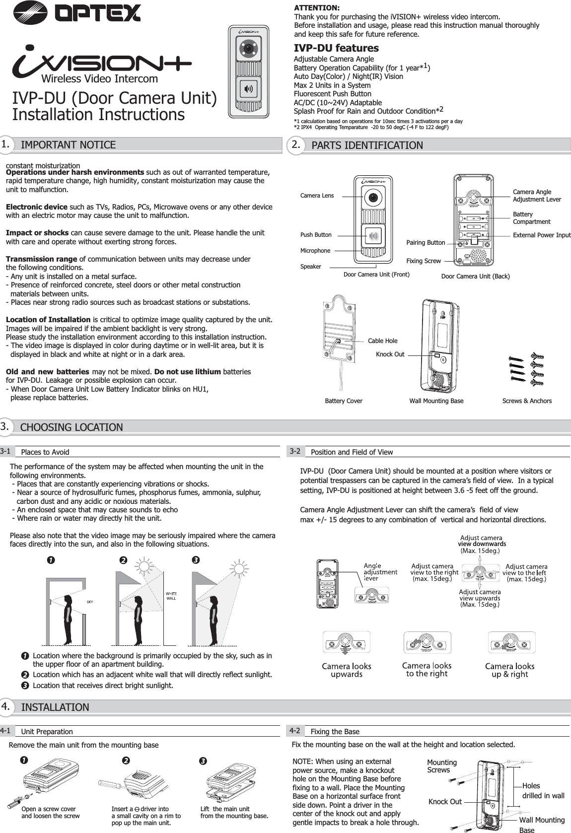
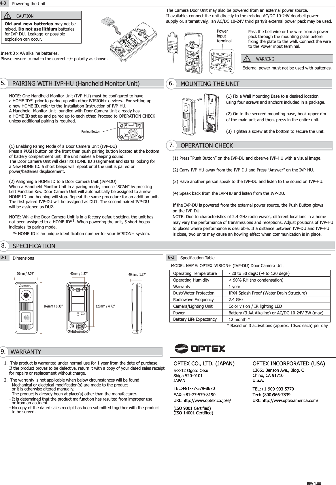
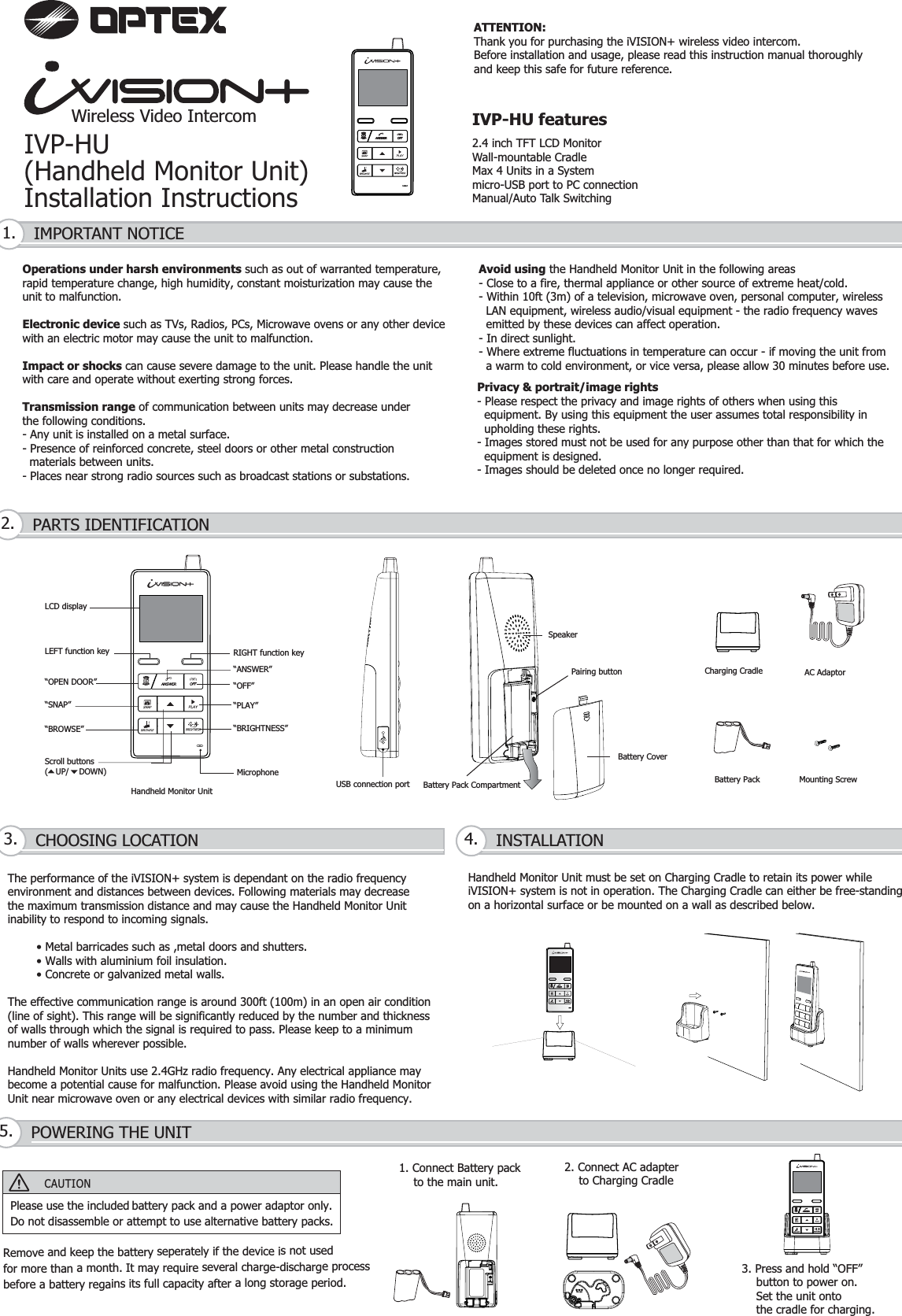
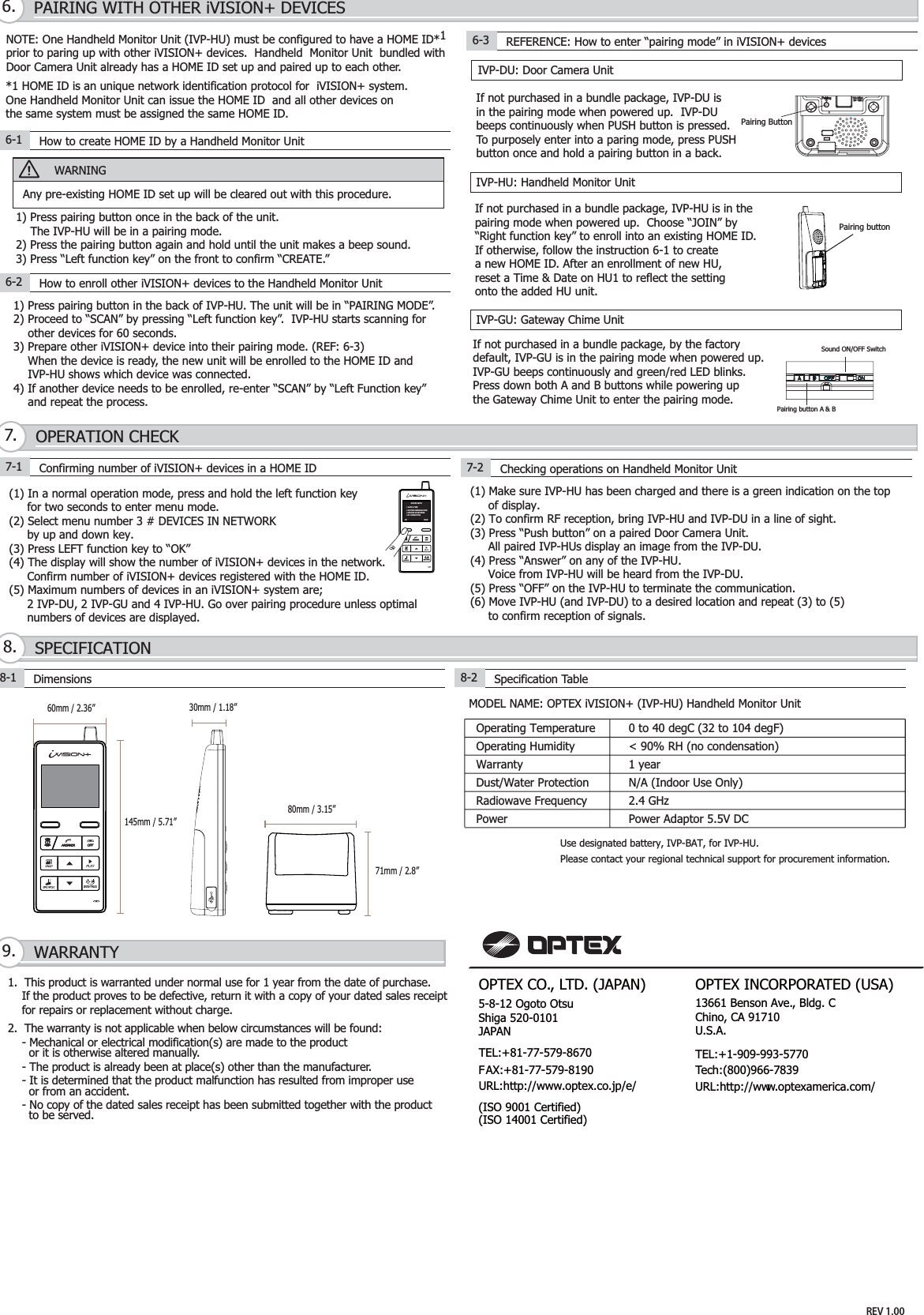
Ox Co IVP-DU Door Camera Unit User Manual

Optex Co Ltd Door Camera Unit Users Manual

Users Manual

Wireless Video IntercomIVP-DU (Door Camera Unit)Installation InstructionsThe performance of the system may be affected when mounting the unit in the following environments. - Places that are constantly experiencing vibrations or shocks. - Near a source of hydrosulfuric fumes, phosphorus fumes, ammonia, sulphur,   carbon dust and any acidic or noxious materials. - An enclosed space that may cause sounds to echo  - Where rain or water may directly hit the unit.Please also note that the video image may be seriously impaired where the camerafaces directly into the sun, and also in the following situations.Location where the background is primarily occupied by the sky, such as inthe upper floor of an apartment building.Location which has an adjacent white wall that will directly reflect sunlight.Location that receives direct bright sunlight.IVP-DU featuresAdjustable Camera AngleBattery Operation Capability (for 1 year*1)Auto Day(Color) / Night(IR) VisionMax 2 Units in a SystemFluorescent Push ButtonAC/DC (10~24V) AdaptableSplash Proof for Rain and Outdoor Condition*2*1 calculation based on operations for 10sec times 3 activations per a day*2 IPX4  Operating Temparature  -20 to 50 degC (-4 F to 122 degF)IMPORTANT NOTICE1. PARTS IDENTIFICATION2.constant moisturizationOperations under harsh environments such as out of warranted temperature, rapid temperature change, high humidity, constant moisturization may cause theunit to malfunction.Electronic device such as TVs, Radios, PCs, Microwave ovens or any other devicewith an electric motor may cause the unit to malfunction.Impact or shocks can cause severe damage to the unit. Please handle the unitwith care and operate without exerting strong forces.Transmission range of communication between units may decrease underthe following conditions. - Any unit is installed on a metal surface.- Presence of reinforced concrete, steel doors or other metal construction  materials between units.- Places near strong radio sources such as broadcast stations or substations.Location of Installation is critical to optimize image quality captured by the unit.Images will be impaired if the ambient backlight is very strong. Please study the installation environment according to this installation instruction.- The video image is displayed in color during daytime or in well-lit area, but it is   displayed in black and white at night or in a dark area.Old and new batteries may not be mixed. Do not use lithium batteriesfor IVP-DU. Leakage or possible explosion can occur.- When Door Camera Unit Low Battery Indicator blinks on HU1,   please replace batteries. CHOOSING LOCATION3.Cable HoleScrews & AnchorsWall Mounting BaseBattery Cover3-1 Places to Avoid3-2Position and Field of ViewIVP-DU  (Door Camera Unit) should be mounted at a position where visitors orpotential trespassers can be captured in the camera’s field of view.  In a typicalsetting, IVP-DU is positioned at height between 3.6 -5 feet off the ground.Camera Angle Adjustment Lever can shift the camera’s  field of view max +/- 15 degrees to any combination of  vertical and horizontal directions.   Knock OutRemove the main unit from the mounting baseOpen a screw coverand loosen the screwLift  the main unit from the mounting base.Fix the mounting base on the wall at the height and location selected.INSTALLATION4.4-1 Unit Preparation 4-2 Fixing the BasePush ButtonCamera LensMicrophoneSpeakerDoor Camera Unit (Front)Camera AngleAdjustment LeverBatteryCompartmentPairing ButtonExternal Power InputFixing ScrewDoor Camera Unit (Back)NOTE: When using an externalpower source, make a knockouthole on the Mounting Base beforefixing to a wall. Place the MountingBase on a horizontal surface frontside down. Point a driver in thecenter of the knock out and applygentle impacts to break a hole through.view downwardsWall MountingBaseHolesdrilled in wallMountingScrews10~24Insert a    driver intoa small cavity on a rim topop up the main unit.ATTENTION:Thank you for purchasing the iVISION+ wireless video intercom.Before installation and usage, please read this instruction manual thoroughlyand keep this safe for future reference.Knock Out
The Camera Door Unit may also be powered from an external power source. If available, connect the unit directly to the existing AC/DC 10-24V doorbell power supply or, alternatively,  an AC/DC 10-24V third party’s external power pack may be used.Pass the bell wire or the wire from a powerpack through the mounting plate before fixing the plate to the wall. Connect the wireto the Power input terminal.Powerinputterminal(1) Fix a Wall Mounting Base to a desired locationusing four screws and anchors included in a package.(2) On to the secured mounting base, hook upper rimof the main unit and then, press in the entire unit.(3) Tighten a screw at the bottom to secure the unit. NOTE: One Handheld Monitor Unit (IVP-HU) must be configured to have a HOME ID*1 prior to paring up with other iVISION+ devices.  For setting upa new HOME ID, refer to the Installation Instruction of IVP-HU. A Handheld  Monitor Unit  bundled with Door Camera Unit already has a HOME ID set up and paired up to each other. Proceed to OPERATION CHECKunless additional pairing is required.(1) Enabling Paring Mode of a Door Camera Unit (IVP-DU)Press a PUSH button on the front then push pairing button located at the bottomof battery compartment until the unit makes a beeping sound.The Door Camera Unit will clear its HOME ID assignment and starts looking fora New HOME ID. 5 short beeps will repeat until the unit is paired orpower/batteries displacement.(2) Assigning a HOME ID to a Door Camera Unit (IVP-DU)When a Handheld Monitor Unit in a paring mode, choose “SCAN” by pressing Left Function Key. Door Camera Unit will automatically be assigned to a newHOME ID and beeping will stop. Repeat the same procedure for an addition unit.The first paired IVP-DU will be assigned as DU1. The second paired IVP-DUwill be assigned as DU2.NOTE: While the Door Camera Unit is in a factory default setting, the unit hasnot been assigned to a HOME ID*1. When powering the unit, 5 short beepsindicates its paring mode.OPTEX INCORPORATED (USA)TEL:+1-909-993-5770Tech:(800)966-7839URL:http://www.optexamerica.com/OPTEX CO., LTD. (JAPAN)(ISO 9001 Certified)(ISO 14001 Certified)5-8-12 Ogoto OtsuShiga 520-0101JAPANTEL:+81-77-579-8670FAX:+81-77-579-8190URL:http://www.optex.co.jp/e/13661 Benson Ave., Bldg. CChino, CA 91710 U.S.A.CAUTIONOld and new batteries may not be mixed. Do not use lithium batteriesfor IVP-DU. Leakage or possibleexplosion can occur.Insert 3 x AA alkaline batteries.Please ensure to match the correct +/- polarity as shown. (1) Press “Push Button” on the IVP-DU and observe IVP-HU with a visual image.(2) Carry IVP-HU away from the IVP-DU and Press “Answer” on the IVP-HU. (3) Have another person speak to the IVP-DU and listen to the sound on IVP-HU.(4) Speak back from the IVP-HU and listen from the IVP-DU.If the IVP-DU is powered from the external power source, the Push Button glowson the IVP-DU. NOTE: Due to characteristics of 2.4 GHz radio waves, different locations in a home may vary the performance of transmissions and receptions. Adjust positions of IVP-HUto places where performance is desirable. If a distance between IVP-DU and IVP-HUis close, two units may cause an howling effect when communication is in place. MODEL NAME: OPTEX iVISION+ (IVP-DU) Door Camera Unit Dust/Water ProtectionOperating TemperatureCamera/Lighting UnitBattery Life ExpectancyRadiowave Frequency9. WARRANTY1.  This product is warranted under normal use for 1 year from the date of purchase.     If the product proves to be defective, return it with a copy of your dated sales receipt     for repairs or replacement without charge.2.  The warranty is not applicable when below circumstances will be found:    - Mechanical or electrical modification(s) are made to the product       or it is otherwise altered manually.    - The product is already been at place(s) other than the manufacturer.    - It is determined that the product malfunction has resulted from improper use      or from an accident.    - No copy of the dated sales receipt has been submitted together with the product      to be served.PAIRING WITH IVP-HU (Handheld Monitor Unit)5. MOUNTING THE UNIT6.OPERATION CHECK7.SPECIFICATION8.4-3 Powering the UnitWARNINGExternal power must not be used with batteries. 8-1 Dimensions8-2Specification Table*1 HOME ID is an unique identification number for your iVISION+ system.  Pairing Button70mm / 2.76” 40mm / 1.57”120mm / 4.72”40mm / 1.57”162mm / 6.38”- 20 to 50 degC (-4 to 120 degF)< 90% RH (no condensation)1 yearIPX4 Splash Proof (Water Drain Structure)2.4 GHz12 month ** Based on 3 activations (approx. 10sec each) per dayOperating HumidityWarrantyPowerColor vision / IR lighting LEDBattery (3 AA Alkaline) or AC/DC 10-24V 3W (max)REV 1.00
Avoid using the Handheld Monitor Unit in the following areas- Close to a fire, thermal appliance or other source of extreme heat/cold.- Within 10ft (3m) of a television, microwave oven, personal computer, wireless  LAN equipment, wireless audio/visual equipment - the radio frequency waves   emitted by these devices can affect operation.- In direct sunlight.- Where extreme fluctuations in temperature can occur - if moving the unit from  a warm to cold environment, or vice versa, please allow 30 minutes before use.IVP-HU features2.4 inch TFT LCD MonitorWall-mountable CradleMax 4 Units in a Systemmicro-USB port to PC connectionManual/Auto Talk SwitchingIVP-HU(Handheld Monitor Unit)Installation InstructionsATTENTION:Thank you for purchasing the iVISION+ wireless video intercom.Before installation and usage, please read this instruction manual thoroughlyand keep this safe for future reference.Wireless Video IntercomIMPORTANT NOTICE1.Privacy & portrait/image rights- Please respect the privacy and image rights of others when using this   equipment. By using this equipment the user assumes total responsibility in   upholding these rights.- Images stored must not be used for any purpose other than that for which the  equipment is designed.- Images should be deleted once no longer required.Operations under harsh environments such as out of warranted temperature, rapid temperature change, high humidity, constant moisturization may cause theunit to malfunction.Electronic device such as TVs, Radios, PCs, Microwave ovens or any other devicewith an electric motor may cause the unit to malfunction.Impact or shocks can cause severe damage to the unit. Please handle the unitwith care and operate without exerting strong forces.Transmission range of communication between units may decrease underthe following conditions.- Any unit is installed on a metal surface.- Presence of reinforced concrete, steel doors or other metal construction  materials between units.- Places near strong radio sources such as broadcast stations or substations.PARTS IDENTIFICATION2.CHOOSING LOCATION3. INSTALLATION4.POWERING THE UNIT5.The performance of the iVISION+ system is dependant on the radio frequencyenvironment and distances between devices. Following materials may decreasethe maximum transmission distance and may cause the Handheld Monitor Unitinability to respond to incoming signals.        • Metal barricades such as ,metal doors and shutters.        • Walls with aluminium foil insulation.        • Concrete or galvanized metal walls.The effective communication range is around 300ft (100m) in an open air condition (line of sight). This range will be significantly reduced by the number and thickness of walls through which the signal is required to pass. Please keep to a minimum number of walls wherever possible.Handheld Monitor Units use 2.4GHz radio frequency. Any electrical appliance may become a potential cause for malfunction. Please avoid using the Handheld MonitorUnit near microwave oven or any electrical devices with similar radio frequency.CAUTIONPlease use the included battery pack and a power adaptor only. Do not disassemble or attempt to use alternative battery packs.Handheld Monitor Unit must be set on Charging Cradle to retain its power whileiVISION+ system is not in operation. The Charging Cradle can either be free-standingon a horizontal surface or be mounted on a wall as described below.Charging CradleMounting ScrewHandheld Monitor UnitAC AdaptorBattery Pack1. Connect Battery pack    to the main unit.LCD displayLEFT function key“OPEN DOOR”“SNAP”“BROWSE”Scroll buttons(   UP/    DOWN) Microphone“BRIGHTNESS”“PLAY”“OFF”“ANSWER”RIGHT function key2. Connect AC adapter    to Charging Cradle3. Press and hold “OFF”    button to power on.    Set the unit onto     the cradle for charging.Remove and keep the battery seperately if the device is not used for more than a month. It may require several charge-discharge processbefore a battery regains its full capacity after a long storage period. Battery Pack CompartmentSpeakerUSB connection portBattery CoverPairing button
1.  This product is warranted under normal use for 1 year from the date of purchase.     If the product proves to be defective, return it with a copy of your dated sales receipt     for repairs or replacement without charge.2.  The warranty is not applicable when below circumstances will be found:    - Mechanical or electrical modification(s) are made to the product       or it is otherwise altered manually.    - The product is already been at place(s) other than the manufacturer.    - It is determined that the product malfunction has resulted from improper use      or from an accident.    - No copy of the dated sales receipt has been submitted together with the product      to be served.WARRANTY9.SPECIFICATION8.OPERATION CHECK7.PAIRING WITH OTHER iVISION+ DEVICES6.MODEL NAME: OPTEX iVISION+ (IVP-HU) Handheld Monitor Unit8-1 Dimensions8-2Specification Table(1) In a normal operation mode, press and hold the left function key     for two seconds to enter menu mode. (2) Select menu number 3 # DEVICES IN NETWORK     by up and down key.(3) Press LEFT function key to “OK”(4) The display will show the number of iVISION+ devices in the network.     Confirm number of iVISION+ devices registered with the HOME ID.(5) Maximum numbers of devices in an iVISION+ system are;     2 IVP-DU, 2 IVP-GU and 4 IVP-HU. Go over pairing procedure unless optimal     numbers of devices are displayed.IVP-DU: Door Camera UnitIVP-GU: Gateway Chime UnitIVP-HU: Handheld Monitor UnitNOTE: One Handheld Monitor Unit (IVP-HU) must be configured to have a HOME ID*1prior to paring up with other iVISION+ devices.  Handheld  Monitor Unit  bundled with Door Camera Unit already has a HOME ID set up and paired up to each other. *1 HOME ID is an unique network identification protocol for  iVISION+ system.  One Handheld Monitor Unit can issue the HOME ID  and all other devices on the same system must be assigned the same HOME ID.WARNINGAny pre-existing HOME ID set up will be cleared out with this procedure.6-1 How to create HOME ID by a Handheld Monitor UnitIf not purchased in a bundle package, IVP-DU isin the pairing mode when powered up.  IVP-DUbeeps continuously when PUSH button is pressed.To purposely enter into a paring mode, press PUSHbutton once and hold a pairing button in a back.1) Press pairing button once in the back of the unit.     The IVP-HU will be in a pairing mode.2) Press the pairing button again and hold until the unit makes a beep sound.3) Press “Left function key” on the front to confirm “CREATE.”6-2 How to enroll other iVISION+ devices to the Handheld Monitor Unit1) Press pairing button in the back of IVP-HU. The unit will be in “PAIRING MODE”.2) Proceed to “SCAN” by pressing “Left function key”.  IVP-HU starts scanning for    other devices for 60 seconds.3) Prepare other iVISION+ device into their pairing mode. (REF: 6-3)    When the device is ready, the new unit will be enrolled to the HOME ID and    IVP-HU shows which device was connected.4) If another device needs to be enrolled, re-enter “SCAN” by “Left Function key”    and repeat the process.    Pairing buttonIf not purchased in a bundle package, IVP-HU is in thepairing mode when powered up.  Choose “JOIN” by “Right function key” to enroll into an existing HOME ID.If otherwise, follow the instruction 6-1 to create a new HOME ID. After an enrollment of new HU,reset a Time & Date on HU1 to reflect the settingonto the added HU unit.If not purchased in a bundle package, by the factorydefault, IVP-GU is in the pairing mode when powered up.IVP-GU beeps continuously and green/red LED blinks.Press down both A and B buttons while powering upthe Gateway Chime Unit to enter the pairing mode.6-3 REFERENCE: How to enter “pairing mode” in iVISION+ devices7-1 Confirming number of iVISION+ devices in a HOME ID 7-2 Checking operations on Handheld Monitor Unit(1) Make sure IVP-HU has been charged and there is a green indication on the top     of display. (2) To confirm RF reception, bring IVP-HU and IVP-DU in a line of sight.(3) Press “Push button” on a paired Door Camera Unit.      All paired IVP-HUs display an image from the IVP-DU.(4) Press “Answer” on any of the IVP-HU.     Voice from IVP-HU will be heard from the IVP-DU.(5) Press “OFF” on the IVP-HU to terminate the communication.(6) Move IVP-HU (and IVP-DU) to a desired location and repeat (3) to (5)     to confirm reception of signals.80mm / 3.15”71mm / 2.8”Operating TemperatureDust/Water ProtectionRadiowave Frequency0 to 40 degC (32 to 104 degF)< 90% RH (no condensation)1 yearN/A (Indoor Use Only)2.4 GHzOperating HumidityWarrantyPower Power Adaptor 5.5V DCPairing Button60mm / 2.36” 30mm / 1.18”145mm / 5.71”SYSTEM SETUP1 DATE & TIME2 SYSTEM CONFIGURATION3 DEVICES IN NETWORK4 PC CONNECTIONOK BACKPairing button A & BSound ON/OFF SwitchUse designated battery, IVP-BAT, for IVP-HU.Please contact your regional technical support for procurement information. REV 1.00OPTEX INCORPORATED (USA)TEL:+1-909-993-5770Tech:(800)966-7839URL:http://www.optexamerica.com/OPTEX CO., LTD. (JAPAN)(ISO 9001 Certified)(ISO 14001 Certified)5-8-12 Ogoto OtsuShiga 520-0101JAPANTEL:+81-77-579-8670FAX:+81-77-579-8190URL:http://www.optex.co.jp/e/13661 Benson Ave., Bldg. CChino, CA 91710 U.S.A.
W ir eless Video IntercomFCC Statement This device complies with Part 15 of the FCC Rules. Operation is subject to the following two conditions: (1) This device may not cause harmful interference, and (2) this device must accept any interference received, including interference that may cause undesired operation. Any Changes or modifications not expressly approved by party responsible for compliance coulk void the user’sauthority to operate the equipment.   Note: This equipment has been tested and found to comply with the limits for a Class B digital device, pursuant to part 15 of the FCCRules. These limits are designed to provide reasonable protection against harmful interference in a residential installation. Thisequipment generates, uses and can radiate radio frequency energy and, if not installed and used in accordance with the instructionsmay cause harmful interference to radio communications. However, there is no guarantee that interference will not occur in a particular installation. If this equipment does cause harmful interference to radio or television reception, which can be determinedby turning the equipment off and on, the user is encouraged to try to correct the interference by one or more of the following measures: —Reorient or relocate the receiving antenna. —Increase the separation between the equipment and receiver. —Connect the equipment into an outlet on a circuit different from that to which the receiver is connected. —Consult the dealer or an experienced radio/TV technician for help. Radiation Exposure Statement This equipment complies with FCC radiation exposure limits set forth for an uncontrolled environment. This transmitter must not beco-located or operating in conjunction with any other antenna or transmitter.(see ** )  IC RSS warning   This device complies with Industry Canada licence-exempt RSS standard (s). Operation is subject to the following two conditions: (1) this device may not cause interference, and (2) this device must accept any interference,including interference that may causeundesired operation of the device.   Le présent appareil est conforme aux CNR d'Industrie Canada applicables aux appareils radio exempts de licence.  L'exploitation est autorisée aux deux conditions suivantes:  (1) l'appareil ne doit pas produire de brouillage, et   (2) l'utilisateur de l'appareil doit accepter tout brouillage radioélectrique subi, même si le brouillage est susceptible d'en compromettre le fonctionnement. Under Industry Canada regulations, this radio transmitter may only operate using an antenna of a type and maximum (or lesser)gain approved for the transmitter by Industry Canada. To reduce potential radio interference to other users, the antenna type andits gain should be so chosen that, the equivalent isotropically radiated power (e.i.r.p.) is not more than that necessary for successfulcommunication. Conformément à la réglementation d'Industrie Canada, le présent émetteur radio peut fonctionner avec une antenne d'un type etd'un gain maximal (ou inférieur) approuvé pour l'émetteur par Industrie Canada. Dans le but de réduire les risques de brouillage radioélectrique à l'intention des autres utilisateurs, il faut choisir le type d'antenne et son gain de sorte que la puissance isotrope rayonnée équivalente (p.i.r.e.) ne dépasse pas l'intensité nécessaire à l'établissement d'une communication satisfaisante. (1/2) This radio transmitter (identify the device by certification number, or model number if Category II) has been approved by Industry Canada to operate with the antenna types listed below with the maximum permissible gain and required antenna impedance for each antenna type indicated. Antenna types not included in this list, having a gain greater than the maximum gainindicated for that type, are strictly prohibited for use with this device. Le présent émetteur radio (identifier le dispositif par son numéro de certification ou son numéro de modèle s'il fait partie du matérielde catégorie I) a été approuvé par Industrie Canada pour fonctionner avec les types d'antenne énumérés ci-dessous et ayant un gain admissible maximal etl'impédance requise pour chaque type d'antenne. Les types d'antenne non inclus dans cette liste,   ou dont le gain est supérieur au gain maximal indiqué, sont strictement interdits pour l'exploitation de l'émetteur. IC Radiation Exposure Statement:  This equipment complies with IC RF radiation exposure limits set forth for an uncontrolled environment. This transmitter must notbe co-located or operating in conjunction with any other antenna or transmitter. (see    **)  ** For DU and GU, the equipment should be installed and operated with minimum distance 20cm between the radiator & your body.

Navigation menu