User Manual
and manufactured
in Germany
designed
Innovation in Radar Technology
User Manual
CONFIDENTIAL AND PROPRIETARY
The information contained in this document shall remain the sole and exclusive property of InnoSenT GmbH and shall not be
disclosed by the recipient to third parties without prior consent of InnoSenT in writing.
Page 1 USER MANUAL IVS-166 Version 1.0
PRODUCT FAMILY
APPLICATIONS
FEATURES:
DESCRIPTION
ADDITIONAL INFORMATION
InnoSenT Standard Product. Changes will not be
notified as long as there is no influence on form, fit
and within this datasheet specified function of the
product.
RoHS-INFO
This product is compliant to the restriction of
hazardous substances (RoHS - European Union
directive 2011/65/Eu).
CERTIFICATES
InnoSenT GmbH has established and applies a
quality system for: development, production and
sales of radar sensors for industrial and automotive
sensors.
Version
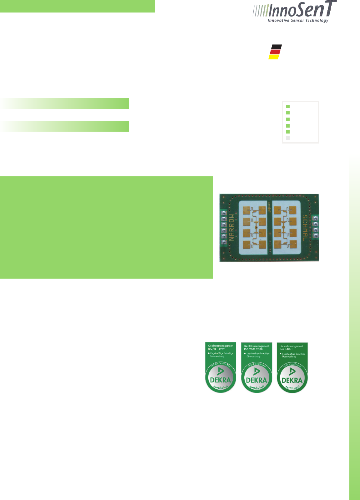
The IVS-166 is the FMCW/FSK-version of the IPS-
154. The same outline dimensions as well as the
identical antenna pattern make this product perfect
for upgrading existing systems
1.0 - 03.12.2013
IVS-166
K-Band VCO Transceiver
• Industrial Applications
• Door Opener
Movement
Velocity
Direction
Presence
Distance
Angle
»VCO-Transceiver centered @ 24GHz
»FMCW/FSK capable; therefore measurement of distance as well
as recognition of stationary objects possible (depending on
modulation)
»split transmit and receive path for maximum gain
»stereo (dual channel) operation for direction of motion indection
»IF-pre-amplifier, bandwith limited for lowest noise performance
»compact outline dimensions

Innovation in Radar Technology
CONFIDENTIAL AND PROPRIETARY
The information contained in this document shall remain the sole and exclusive property of InnoSenT GmbH and shall not be
disclosed by the recipient to third parties without prior consent of InnoSenT in writing.
Page 2 USER MANUAL IVS-166 Version 1.0
ELECTRICAL CHARACTERISTICS
PARAMETER CONDITIONS SYMBOL MIN TYP MAX UNITS
Transmitter
transmit frequencies depending on Vtune f 24.000 - 24.250 GHz
freq @ Vtune 5,0V @ 25°C f5,0V 24.100 24.125 24.150 GHz
varactor tuning voltage Vtune 0.5 10 V
varactor tuning impedance 10k kΩ
modulation input 150 kHz
tuning slope 40 MHz/V
temperature drift (frequency) Δf -1 MHz/°C
output power (EIRP) @ 25°C Pout 15 dBm
Receiver
I/Q balance amplitude 6 dB
phase 60 90 120 °
IF-output voltage offset 1. 0 2.2 4.0 V
IF - amplifier bandwidth DC - 50 kHz
gain 20 dB
Antenna System Pattern (compare with antenna plot on page 3)
full beam width @ -3dB azimuth horizontal 45 °
elevation vertical 38 °
side-lobe suppression azimuth horizontal 15 dB
elevation vertical 20 dB
Power supply
supply voltage VCC 4.75 5.00 5.25 V
supply current IF-amp included ICC 35 50 mA
Environment
operating temperature TOP -20 +60 °C
storage temperature TSTG -40 +85 °C
Mechanical Outlines
outline dimensions compare drawing
height
length
width
8.3 (19)
44.0
30.0
mm
Innovation in Radar Technology
CONFIDENTIAL AND PROPRIETARY
The information contained in this document shall remain the sole and exclusive property of InnoSenT GmbH and shall not be
disclosed by the recipient to third parties without prior consent of InnoSenT in writing.
Page 3 USER MANUAL IVS-166 Version 1.0
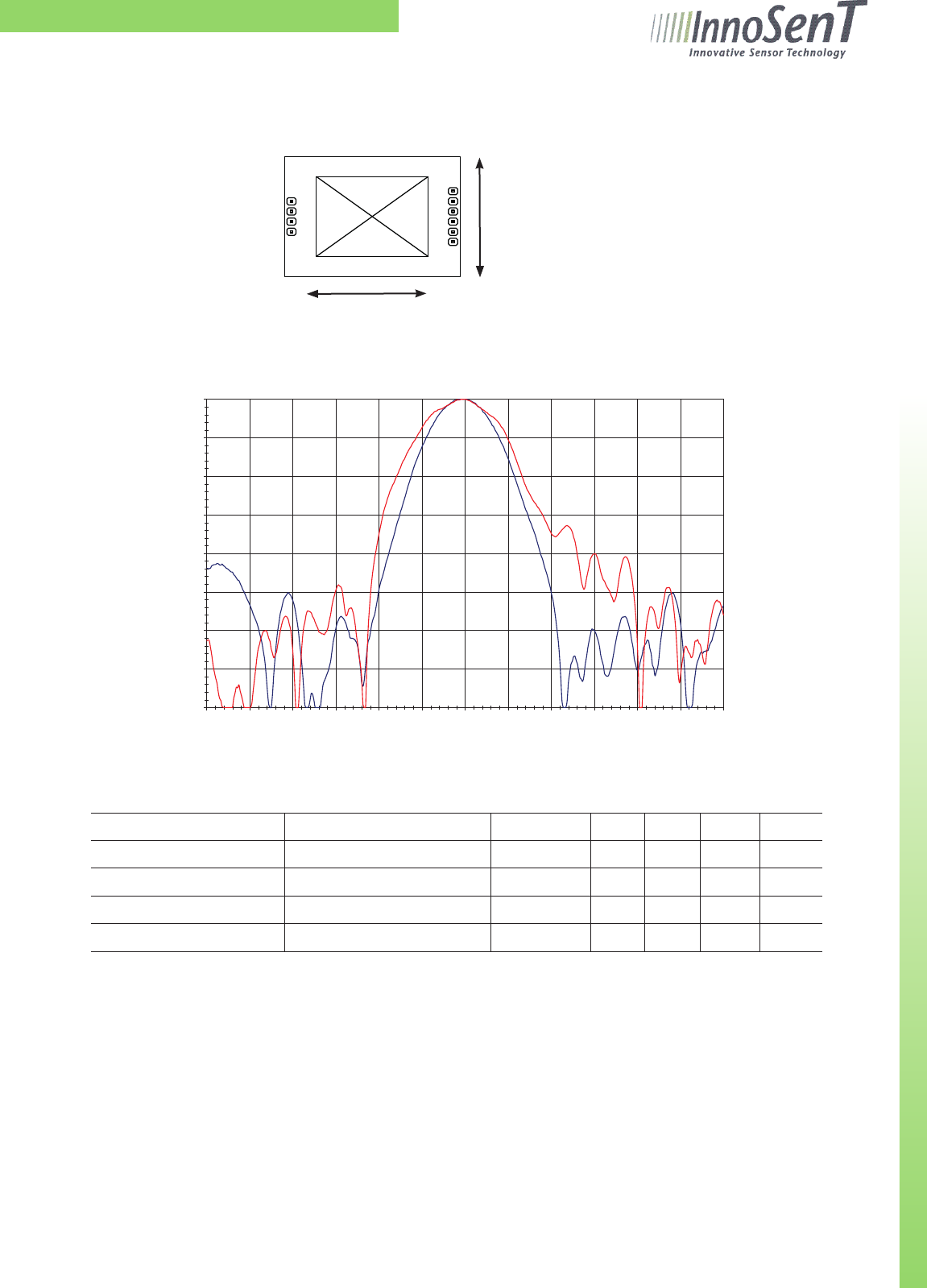
TX- ANTENNA PATTERN
Antenna Orientation:
PARAMETER CONDITIONS SYMBOL MIN TYP MAX UNITS
full beam width @ -3dB horizontal 45 °
vertical 38 °
side-lobe suppression horizontal 15 dB
vertical 20 dB
horizontal
vercal
antenna
angle [°]
output power [dBm]
-40
-35
-30
-25
-20
-15
-10
-5
0
-180,0 -150,0 -120,0 -90,0 -60,0 -30,0 0,0 30,0 60,0 90,0 120,0 150,0 180,0
Innovation in Radar Technology
CONFIDENTIAL AND PROPRIETARY
The information contained in this document shall remain the sole and exclusive property of InnoSenT GmbH and shall not be
disclosed by the recipient to third parties without prior consent of InnoSenT in writing.
Page 4 USER MANUAL IVS-166 Version 1.0
PIN # DESCRIPTION IN / OUT COMMENT
1 Vtune input varactor tuning voltage
2 enable input active low
3 Vcc input supply voltage (+5 V)
4 GND input analog ground
5 IF1 output signal I(nphase)
6 IF2 output signal Q(uadrature)
7 GND input analog ground
8 GND input analog ground
9 NC not connected
10 NC not connected
INTERFACE
The sensor provides a 2.54mm grid, single row pin header (square pin 0.635mm).
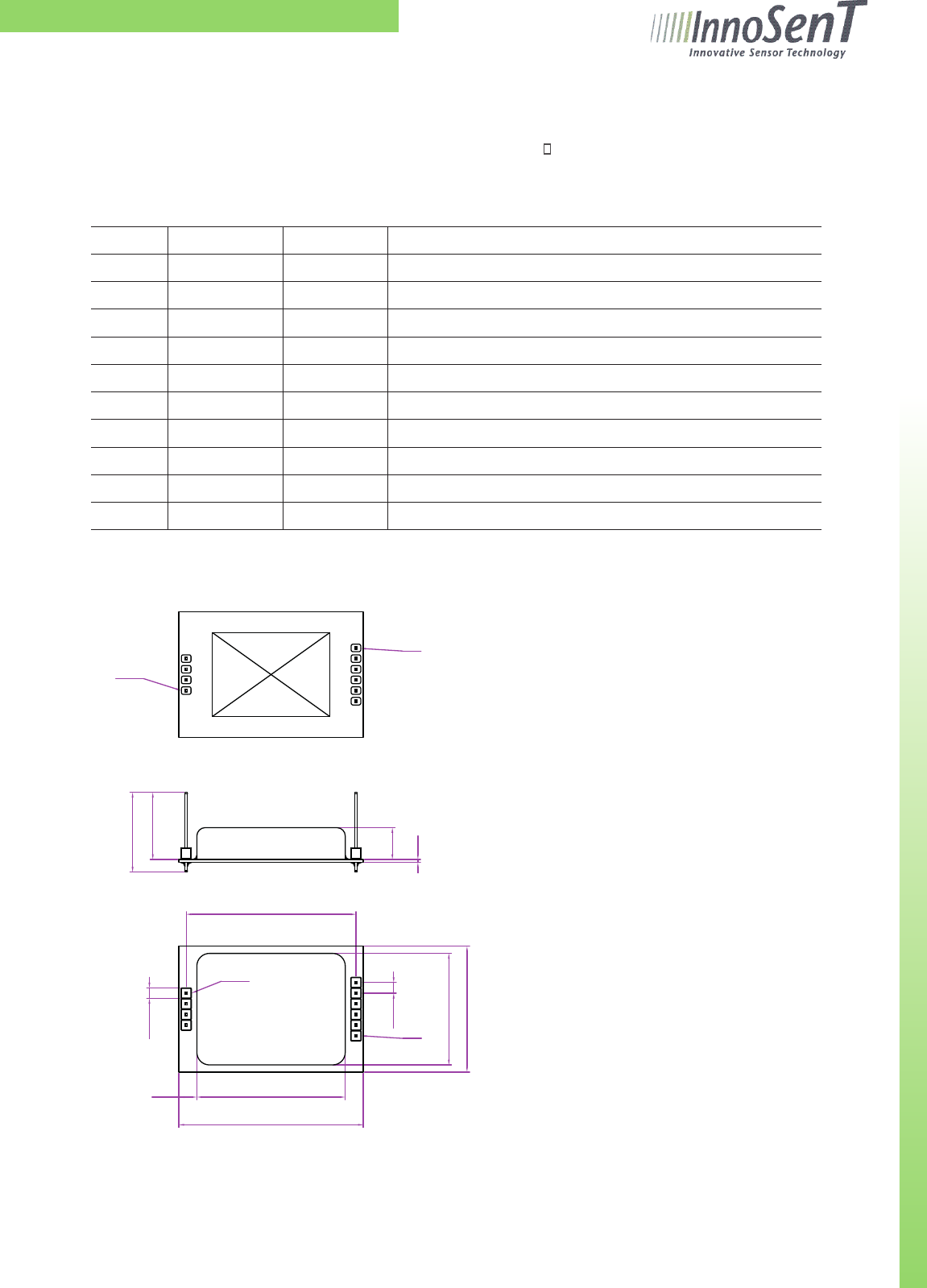
MECHANICAL OUTLINES
side view
bottom view
top view
30
4x2.54
44
35.4
4.3
40.5
backside
6x2.54
26.6
PIN1
19
16
all dimensions in mm
antenna
7.6
0.7
PIN1
PIN10
PIN10

Innovation in Radar Technology
CONFIDENTIAL AND PROPRIETARY
The information contained in this document shall remain the sole and exclusive property of InnoSenT GmbH and shall not be
disclosed by the recipient to third parties without prior consent of InnoSenT in writing.
Page 5 USER MANUAL IVS-166 Version 1.0
NOTICE:
This device complies with Part 15 of the FCC Rules [and with Industry Canada licence-exempt RSS standard(s)].
Operation is subject to the following two conditions:
(1) this device may not cause harmful interference, and
(2) this device must accept any interference received, including interference that may cause undesired operation.
Le présent appareil est conforme aux CNR d’Industrie Canada applicables aux appareils radio
exempts de licence. L’exploitation est autorisée aux deux conditions suivantes:
(1) l’appareil ne doit pas produire de brouillage, et
(2) l’utilisateur de l’appareil doit accepter tout brouillage radioélectrique subi, même si le brouillage est susceptible d’en
compromettre le fonctionnement.
NOTICE:
Changes or modications made to this equipment not expressly approved by (manufacturer name) may void the FCC
authorization to operate this equipment.
Text for User Manual (blue cursive text)
For a Class A digital device or peripheral, the instructions furnished the user shall include the following or similar state-
ment, placed in a prominent location in the text of the manual:
NOTE: This equipment has been tested and found to comply with the limits for a Class A digital device, pursuant to Part 15
of the FCC Rules. These limits are designed to provide reasonable protection against harmful interference when the equip-
ment is operated in a commercial environment. This equipment generates, uses, and can radiate radio frequency energy
and, if not installed and used in accordance with the instruction manual, may cause harmful interference to radio commu-
nications. Operation of this equipment in a residential area is likely to cause harmful interference in which case the user will
be required to correct the interference at his own expense.

Innovation in Radar Technology
CONFIDENTIAL AND PROPRIETARY
The information contained in this document shall remain the sole and exclusive property of InnoSenT GmbH and shall not be
disclosed by the recipient to third parties without prior consent of InnoSenT in writing.
Page 6 USER MANUAL IVS-166 Version 1.0
FCC approval
Changes or modifications made to the equipment not expressly approved by InnoSenT GmbH may void the
FCC / IC authorization to operate this equipment.
The use of the transceiver module is authorized in mobile or fixed host devices taking into account the
conditions listed below:
•OEMIntegratormustensurethattheendusermanualmaynotcontainanyinformationaboutthewayto
install or remove the module from the final product.
•Dependingonthenalhostdeviceadditionalauthorizationrequirementsforthenon-transmitterfunctions
of the transmitter module may be required (i.e., Verification, or Declaration of Conformity) The OEM integ-
rator is responsible for ensuring that after the module is installed and operational the host continues to be
compliant with the Part 15B unintentional radiator requirements.
•Theinformationonthelabelandintheusermanualisrequiredtobeincorporatedintheusermanualof
the final host. see 47 CFR15 requirements for more details (e.g. 15.19 / 15.21 / 15.101 / 15.105 / RSS-GEN /
ICES)
•Additionallabelwiththewords‘ContainsFCCID:DC9-IVS166’and‘ContainsIC:4012A-IVS166’shallbe
applied and visible from the outside of the host product.
•Themodulemustbeinstalledandusedinstrictaccordancewiththemanufacturer’sinstructionsasde-
scribed in the user documentation that comes with the module.
•Theendusermanualforthenalhostproductoperatingwiththistransmittermustincludeoperating
instructions to satisfy RF exposure compliance requirements.
e.g
Radiofrequency radiation exposure Information:
This equipment complies with FCC radiation exposure limits set forth for an uncontrolled environment. This equip-
ment should be installed and operated with minimum distance of 20 cm between the radiator and your body.
This transmitter must not be co-located or operating in conjunction with any other antenna or transmitter.
•Theantennaofthemodulemaynotberemoved,replacednormodied.Theantennamustnotbeco-loca-
ted or operating in conjunction with any other antenna or transmitter. No additional antenna must be used.
•Whenthenalhostproductoperatingwiththistransmitterdeviatefromabove,installationofthismodule
into specific final hosts may require the submission of a Class II permissive change application containing
data pertinent to RF Exposure, spurious emissions, ERP/EIRP, and host/module authentication, or new
application if appropriate.

Innovation in Radar Technology
Page 7 USER MANUAL IVS-166 Version 1.0
InnoSenT GmbH
Am Rödertor 30
97499 Donnersdorf
GERMANY
Tel.:
E-Mail:
URL:
+49 (0) 9528 - 9518 - 0
info@innosent.de
www.innosent.de
VERSION DATE COMMENT
1. 0 03.12.2013 Creating user manual IVS-166
APPROVAL
This Data Sheet contains the technical specifications of the described product. All previous versions of this Data
Sheet are no longer valid.
The sensor uses Hydrocarbon based material which may change its dielectric properties when used in an oxidati-
ve environment. This may vary based on temperature. Therefore InnoSenT recommends evaluating this influence
within the specific environment.