Ox Co TD-20U INDOOR/OUTDOOR SENSOR TRANSMITTER User Manual TD 20U IM p1 Black A4 150110 LR
Optex Co Ltd INDOOR/OUTDOOR SENSOR TRANSMITTER TD 20U IM p1 Black A4 150110 LR
UserManual.wiki
>
Ox Co
>
TD 20U User Manual
User manual
Navigation menu
Upload a User Manual
Namespaces
Wiki Guide
HTML
PDF
Info
Views
User Manual
Discussion / Help
Navigation
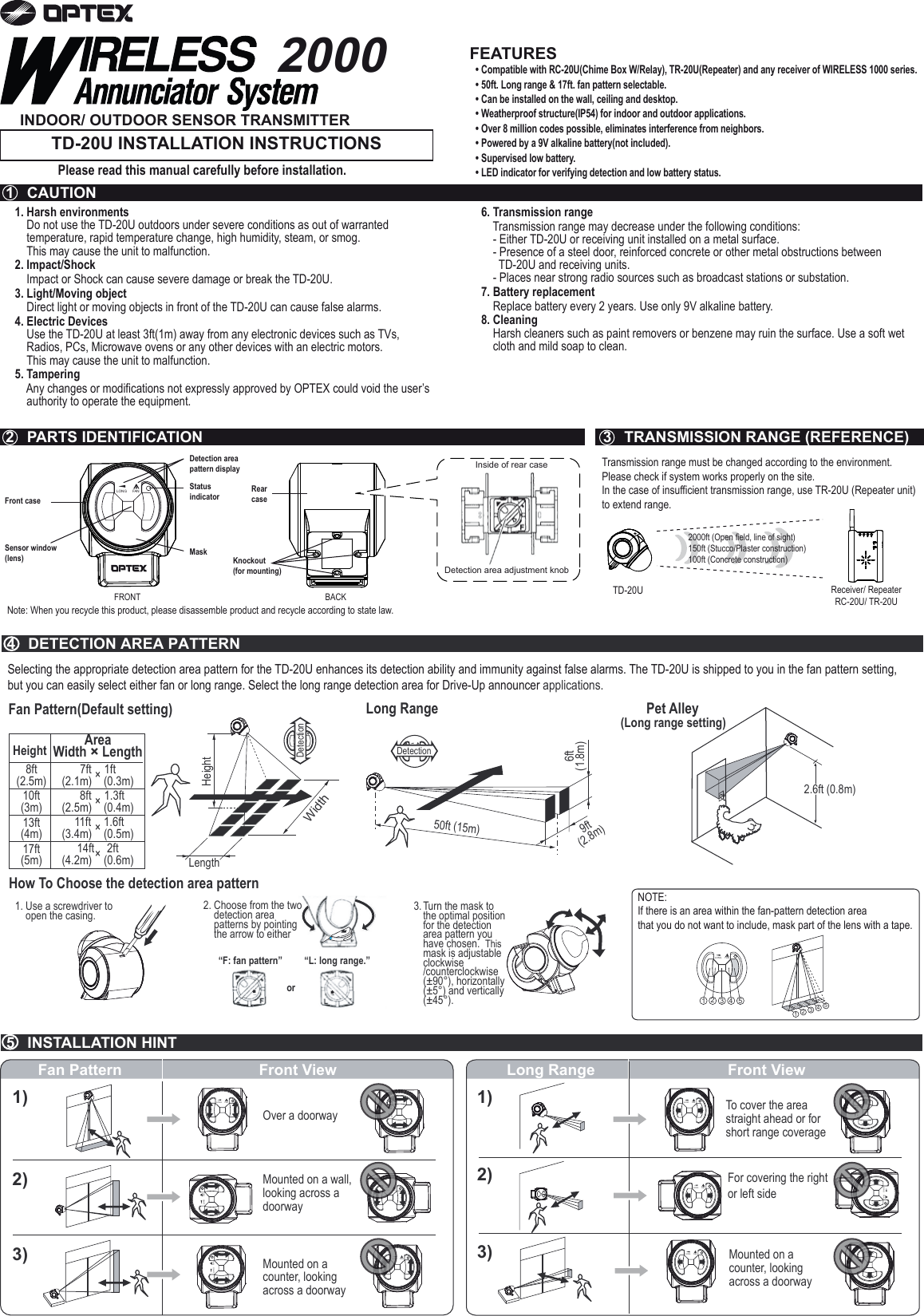
![LONG FAN LONG FAN Unit: inches (mm)• When the power is low, the status indicator starts to flash. Replace the battery in such cases, even if it is less than a year old.• Low power may become the cause of false alarm.• There is no need to readjust the TD-20U or the receiver after replacing batteries.The receiver must be taught this transmitter code before use. Refer to the receiver’s manual for details.1. Preparation• Press s witch 1 of the receiver until the power indicator starts flashing.• Press switch 2 to select the zone you wish to assign to the sensor.2. Activation• Wave your hand in front of the TD-20U to trigger it.• Verity that the receiver has learned successfully by observing the zone indicators of the receiver. Zone indicators should havsremaintopped flashing and continuously 3. Verification• After teaching all the transmitter codes (if you have multiple transmitters), return the receiver to normal operating status.• Make sure that the receiver operates correctly with all the transmitters.Note:Cover the TD-20U until you are ready to teach the receiver. Unwanted detection can cause the TD-20U to be assigned to the wrong zone and override the data of other transmitters.1. The system is not operating.Check the transmitter.Does the status indicator light up when you walk in front of the TD-20U? If not, check to see whether the battery is inserted correctly. Otherwise try a new battery.Is the detection area setting appropriate?If not, fix the setup.Is the status indicator flashing? The battery is old. Replace the battery.Check the receiver.Is the power indicator of the receiver lit? Is the receiver on? Check the wiring, power switch and connection.The receiver does not respond to the TD-20U. The TD-20U is not properly recognized by the receiver. Teach the receiver correctly.The zone indicator of the receiver is on, but nothing happens. The receiver has not been properly setup. Refer to the receiver’s manual and verify the setting.Is there anything blocking the transmission? Relocate the receiver and/or the TD-20U. Metal objects can shorten the effective transmission range.2. The system is not operating correctly.A particular zone is malfunctioning. This is probably the transmitter’s problem. Check the TD-20U using this zone.Are there small animals in the area? Refer to the Pet Alley section in 4 DETECTION AREA PATTERN.Does direct sunlight or light from automobiles enter the sensor window? Reorient the TD-20U to avoid such light sources.Is the TD-20U installed on a stable platform? Relocate the TD-20U to a stable platform.Is there anything that may cause rapid temperature change in the detection area? (e.g. stove)Remove any objects that may cause rapid temperature change from the detection area.Is there anything that may cause rapid temperature change of the TD-20U?(e.g. air conditioner)Relocate the TD-20U elsewhere.Before contacting the supplier! Remove the battery, then reinsert the same batteries and verify the TD-20U’s operation again.• If the above solutions do not work, please contact your supplier for services.Model DescriptionDetection MethodDetection AreaAngle AdjustmentStatus IndicatorPower SourceBattery LifeFrequency Operating TemperatureInstallation LocationWeightTD-20UIndoor/ Outdoor Sensor TransmitterPassive Infrared50ft (15m) Long Range / 17ft (5m) Fan Pattern45° Vertically & ±± 5° Horizontallyor± 5° Vertically & 45° HorizontallyRed LED9V Alkaline BatteryApprox. 2 years [250 times per day at 70°F (20°C)]418MHz15°F ~ 120°F (-10°C ~ +50°C)Outdoor / IndoorAccessories Mounting Screw × 26.3 oz (180g)Specifications may change without noticeLong Range Fan Pattern Long Range Fan PatternDetection directionDetection directionDetection directionDetection direction6 INSTALLATION7 CONFIRMATION9 TEACH TRANSMITTER CODES TO THE RECEIVER “TEACH MODE”10 TROUBLESHOOTING 11 SPECIFICATIONS12 DIMENSIONS14 WARRANTY13 COMPLIANCE8 LOW BATTERY1. Actually walk and make sure that the detection area covers the intended area.2. Verify that the status indicator agrees with the detection pattern you chose.3. Verify that the movement direction and detection direction area are the same.4. Remove the knockouts of the rear cover and fix the rear cover in place using screws.5. Close the casing.[Inside]1. This product is warranted under normal use for 2 years from the date of purchase. If the product proves to be defective, return it with a copy of your dated sales receipt for repairs or replacement without charge.2. The warranty is not applicable when below circumstances will be found: • Mechanical or electrical modification(s) are made to the product or it is otherwise altered manually. • The product is already been serviced at place(s) other than the manufacturer. • It is determined that the product malfunction has resulted from improper use or from an accident. • No copy of the dated sales receipt has been submitted together with the product to be serviced.FCC ID : DC9TD-20UThe changes or modifications not expressly approved by the OPTEX could void the user’s authority to operate the equipment.To comply with the FCC RF exposure compliance requirements, this device and its antenna must not be co-located or operating to conjunction with any other antenna or transmitter.Note: This equipment has been tested and found to comply with the limits for a Class B Digital Device, pursuant to part 15 of the FCC Rules. These limits are designed to provide reasonable protection against harmful interference in a residential installation. This equipment generates, uses and can radiate radio frequency energy and, if not installed and used in accordance with the instruction, may cause harmful interference to radio communication. However, there is no grantee that interference will not occur in a particular installation. If this equipment dose cause harmful interference to radio or television reception, which can be determined by turning the equipment off and on , the user is encouraged to try to correct the interference by one or more of the following measures.(1)Reorient or relocate the receiving antenna.(2)Increase the separation between the equipment and receiver.(3)Connect the equipment into an outlet on a circuit different from that to which the receiver is connected.(4)Consult the dealer or an experienced radio/TV technician for help.IC ID : 4012A-000000TD20UOperation is subject to the following two conditions.(1)this device may not cause interference, and (2) this device must accept any interference, including interference that may cause undesired operation of the device.To reduce potential radio interference to other users, the antenna type and its gain should be so chosen that the equivalent isotropically radiated power (e.i.r.p.) is not more than that permitted for successful communication.3. Fasten the battery with the battery clamp hook.2. Attach the connector to the battery.1. Use a screwdriver to open the casing.LONG FANLONG FANLONG FANe on. LONG FANLONG FAN3.22 (81.9) 4.50 (114.2)4.12 (104.6)5916480](https://usermanual.wiki/Ox-Co/TD-20U/User-Guide-1261857-Page-2.png)