Ox Co TD-20U INDOOR/OUTDOOR SENSOR TRANSMITTER User Manual TD 20U IM p1 Black A4 150110 LR
Optex Co Ltd INDOOR/OUTDOOR SENSOR TRANSMITTER TD 20U IM p1 Black A4 150110 LR
Ox Co >
User manual
2000
Transmission range must be changed according to the environment.
Please check if system works properly on the site.
In the case of insufficient transmission range, use TR-20U (Repeater unit)
to extend range.
Receiver/ Repeater
RC-20U/ TR-20U
TD-20U
Note: When you recycle this product, please disassemble product and recycle according to state law.
TD-20U INSTALLATION INSTRUCTIONS
INDOOR/ OUTDOOR SENSOR TRANSMITTER
Please read this manual carefully before installation.
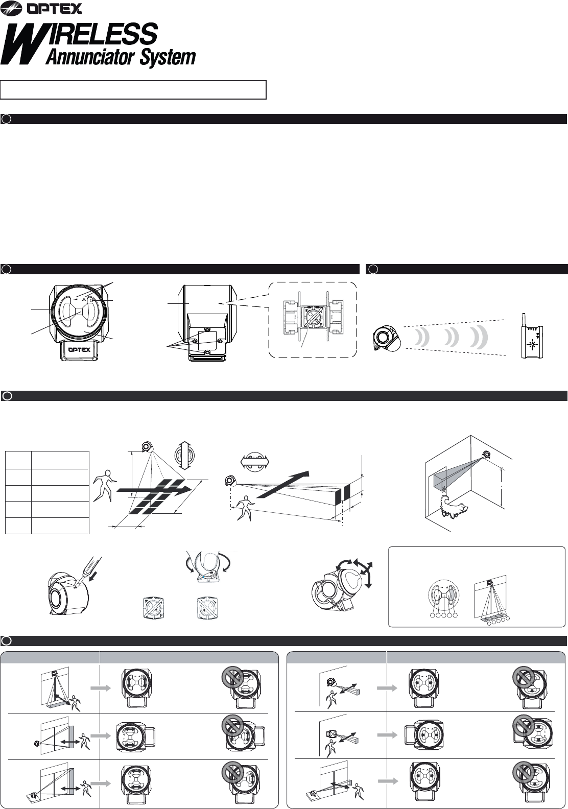
2 PARTS IDENTIFICATION
1 CAUTION
3 TRANSMISSION RANGE (REFERENCE)
2000ft (Open field, line of sight)
150ft (Stucco/Plaster construction)
100ft (Concrete construction)
6. Transmission range
Transmission range may decrease under the following conditions:
- Either TD-20U or receiving unit installed on a metal surface.
- Presence of a steel door, reinforced concrete or other metal obstructions between
TD-20U and receiving units.
- Places near strong radio sources such as broadcast stations or substation.
7. Battery replacement
Replace battery every 2 years. Use only 9V alkaline battery.
8. Cleaning
Harsh cleaners such as paint removers or benzene may ruin the surface. Use a soft wet
cloth and mild soap to clean.
1. Harsh environments
Do not use the TD-20U outdoors under severe conditions as out of warranted
temperature, rapid temperature change, high humidity, steam, or smog.
This may cause the unit to malfunction.
2. Impact/Shock
Impact or Shock can cause severe damage or break the TD-20U.
3. Light/Moving object
Direct light or moving objects in front of the TD-20U can cause false alarms.
4. Electric Devices
Use the TD-20U at least 3ft(1m) away from any electronic devices such as TVs,
Radios, PCs, Microwave ovens or any other devices with an electric motors.
This may cause the unit to malfunction.
5. Tampering
Any changes or modifications not expressly approved by OPTEX could void the user’s
authority to operate the equipment.
FEATURES
•
Compatible with RC-20U(Chime Box W/Relay), TR-20U(Repeater) and any receiver of WIRELESS 1000 series.
•
50ft. Long range & 17ft. fan pattern selectable.
•
Can be installed on the wall, ceiling and desktop.
•
Weatherproof structure(IP54) for indoor and outdoor applications.
•
Over 8 million codes possible, eliminates interference from neighbors.
•
Powered by a 9V alkaline battery(not included).
•
Supervised low battery.
•
LED indicator for verifying detection and low battery status.
Detection area adjustment knob
Inside of rear case
Rear
case
Knockout
(for mounting)
LONG FAN
Detection area
pattern display
Status
indicator
Mask
Front case
Sensor window
(lens)
FRONT BACK
1)
2)
3)
1)
2)
3)
5 INSTALLATION HINT
Fan Pattern Front View Long Range Front View
Over a doorway
Mounted on a
counter, looking
across a doorway
Mounted on a wall,
looking across a
doorway
To cover the area
straight ahead or for
short range coverage
For covering the right
or left side
Mounted on a
counter, looking
across a doorway
LONG FAN
LONG FAN
LONG FAN
LONG FAN
LONG FAN
LONG FAN
LONG FAN
LONG FAN
LONG FAN
LONG FAN
LONG FAN
LONG FAN
LONG FAN
123 4 5
12345
How To Choose the detection area pattern
1. Use a screwdriver to
open the casing. 2. Choose from the two
detection area
patterns by pointing
the arrow to either
.
“F: fan pattern”
or
“L: long range.”
3. Turn the mask to
the optimal position
for the detection
area pattern you
have chosen. This
mask is adjustable
clockwise
/counterclockwise
(±90°), horizontally
(±5°) and vertically
(±45°).
NOTE:
If there is an area within the fan-pattern detection area
that you do not want to include, mask part of the lens with a tape.
4 DETECTION AREA PATTERN
Fan Pattern(Default setting)
Selecting the appropriate detection area pattern for the TD-20U enhances its detection ability and immunity against false alarms. The TD-20U is shipped to you in the fan pattern setting,
but you can easily select either fan or long range. Select the long range detection area for Drive-Up announcer applications.
Height
8ft
(2.5m)
10ft
(3m)
13ft
(4m)
17ft
(5m)
Area
Width × Length
7ft 1ft
(2.1m) × (0.3m)
8ft 1.3ft
(2.5m) × (0.4m)
11ft 1.6ft
(3.4m) × (0.5m)
14ft 2ft
(4.2m) × (0.6m)
Long Range Pet Alley
50ft (15m)
9ft
(2.8m)
6ft
(1.8m)
2.6ft (80cm)2.6ft (0.8m)
LONG FAN
Detection direction
Detection
LONG FAN
Detection direction
Detection
Length
Height
Width
(Long range setting)
LONG FAN
LONG FAN
Unit: inches (mm)
• When the power is low, the status indicator
starts to flash. Replace the battery in such
cases, even if it is less than a year old.
• Low power may become the cause of false
alarm.
• There is no need to readjust the TD-20U or
the receiver after replacing batteries.
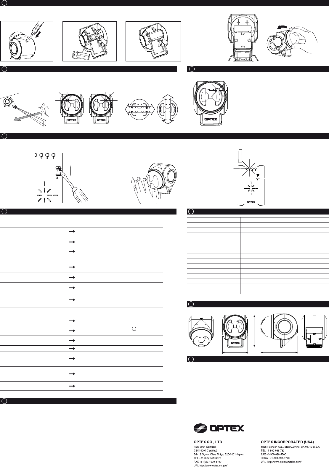
The receiver must be taught this transmitter code before use. Refer to the receiver’s manual for details.
1. Preparation
• Press s witch 1 of
the receiver until
the power indicator
starts flashing.
• Press switch 2 to
select the zone
you wish to assign
to the sensor.
2. Activation
• Wave your hand in front of the TD-20U to trigger it.
• Verity that the receiver
has learned
successfully by
observing the zone
indicators of the
receiver. Zone
indicators should hav
s
remain
topped flashing and
continuously
3. Verification
• After teaching all the
transmitter codes (if
you have multiple
transmitters), return the
receiver to normal
operating status.
• Make sure that the
receiver operates
correctly with all the
transmitters.
Note:
Cover the TD-20U until you are
ready to teach the receiver.
Unwanted detection can cause
the TD-20U to be assigned to the
wrong zone and override the data
of other transmitters.
1. The system is not operating.
Check the transmitter.
Does the status indicator light up when
you walk in front of the TD-20U?
If not, check to see whether the battery is inserted
correctly. Otherwise try a new battery.
Is the detection area setting appropriate?
If not, fix the setup.
Is the status indicator flashing? The battery is old. Replace the battery.
Check the receiver.
Is the power indicator of the receiver lit? Is the receiver on? Check the wiring, power switch
and connection.
The receiver does not respond to the TD-
20U.
The TD-20U is not properly recognized by the
receiver. Teach the receiver correctly.
The zone indicator of the receiver is on,
but nothing happens.
The receiver has not been properly setup. Refer to
the receiver’s manual and verify the setting.
Is there anything blocking the
transmission?
Relocate the receiver and/or the TD-20U. Metal
objects can shorten the effective transmission
range.
2. The system is not operating correctly.
A particular zone is malfunctioning. This is probably the transmitter’s problem. Check
the TD-20U using this zone.
Are there small animals in the area? Refer to the Pet Alley section in 4 DETECTION
AREA PATTERN.
Does direct sunlight or light from
automobiles enter the sensor window? Reorient the TD-20U to avoid such light sources.
Is the TD-20U installed on a stable platform? Relocate the TD-20U to a stable platform.
Is there anything that may cause rapid
temperature change in the detection
area? (e.g. stove)
Remove any objects that may cause rapid
temperature change from the detection area.
Is there anything that may cause rapid
temperature change of the TD-20U?
(e.g. air conditioner)
Relocate the TD-20U elsewhere.
Before contacting the supplier! Remove the battery, then reinsert the same
batteries and verify the TD-20U’s operation again.
• If the above solutions do not work, please contact your supplier for services.
Model
Description
Detection Method
Detection Area
Angle Adjustment
Status Indicator
Power Source
Battery Life
Frequency
Operating Temperature
Installation Location
Weight
TD-20U
Indoor/ Outdoor Sensor Transmitter
Passive Infrared
50ft (15m) Long Range / 17ft (5m) Fan Pattern
45° Vertically & ±± 5° Horizontally
or
± 5° Vertically & 45° Horizontally
Red LED
9V Alkaline Battery
Approx. 2 years [250 times per day at 70°F (20°C)]
418MHz
15°F ~ 120°F (-10°C ~ +50°C)
Outdoor / Indoor
Accessories Mounting Screw × 2
6.3 oz (180g)
Specifications may change without notice
Long Range Fan Pattern Long Range Fan Pattern
Detection direction
Detection direction
Detection direction
Detection direction
6 INSTALLATION
7 CONFIRMATION
9 TEACH TRANSMITTER CODES TO THE RECEIVER “TEACH MODE”
10 TROUBLESHOOTING 11 SPECIFICATIONS
12 DIMENSIONS
14 WARRANTY
13 COMPLIANCE
8 LOW BATTERY
1. Actually walk and make sure
that the detection area covers
the intended area.
2. Verify that the status indicator
agrees with the detection
pattern you chose.
3. Verify that the movement
direction and detection
direction area are the same.
4. Remove the
knockouts of the
rear cover and fix
the rear cover in
place using screws.
5. Close the casing.
[Inside]
1. This product is warranted under normal use for 2 years from the date of purchase. If the
product proves to be defective, return it with a copy of your dated sales receipt for repairs
or replacement without charge.
2. The warranty is not applicable when below circumstances will be found:
• Mechanical or electrical modification(s) are made to the product or it is otherwise altered
manually.
• The product is already been serviced at place(s) other than the manufacturer.
• It is determined that the product malfunction has resulted from improper use or from an
accident.
• No copy of the dated sales receipt has been submitted together with the product to be
serviced.
FCC ID : DC9TD-20U
The changes or modifications not expressly approved by the OPTEX could void the user’s authority to operate the equipment.To comply
with the FCC RF exposure compliance requirements, this device and its antenna must not be co-located or operating to conjunction with
any other antenna or transmitter.Note: This equipment has been tested and found to comply with the limits for a Class B Digital Device,
pursuant to part 15 of the FCC Rules. These limits are designed to provide reasonable protection against harmful interference in a
residential installation. This equipment generates, uses and can radiate radio frequency energy and, if not installed and used in
accordance with the instruction, may cause harmful interference to radio communication. However, there is no grantee that interference
will not occur in a particular installation. If this equipment dose cause harmful interference to radio or television reception, which can be
determined by turning the equipment off and on , the user is encouraged to try to correct the interference by one or more of the following
measures.(1)Reorient or relocate the receiving antenna.(2)Increase the separation between the equipment and receiver.(3)Connect the
equipment into an outlet on a circuit different from that to which the receiver is connected.(4)Consult the dealer or an experienced
radio/TV technician for help.
IC ID : 4012A-000000TD20U
Operation is subject to the following two conditions.(1)this device may not cause interference, and (2) this device must accept any
interference, including interference that may cause undesired operation of the device.
To reduce potential radio interference to other users, the antenna type and its gain should be so chosen that the equivalent isotropically
radiated power (e.i.r.p.) is not more than that permitted for successful communication.
3. Fasten the battery with the
battery clamp hook.
2. Attach the connector to the
battery.
1. Use a screwdriver to open
the casing.
LONG FAN
LONG FANLONG FAN
e
on.
LONG FAN
LONG FAN
3.22 (81.9) 4.50 (114.2)
4.12 (104.6)
5916480