PAC EK-1000P Access controller with low range proximity reader User Manual 17047
PAC International Limited Access controller with low range proximity reader 17047
UserManual.wiki
>
PAC
>
EK 1000P User Manual
Revised Manual
Navigation menu
Upload a User Manual
Namespaces
Wiki Guide
HTML
PDF
Info
Views
User Manual
Discussion / Help
Navigation


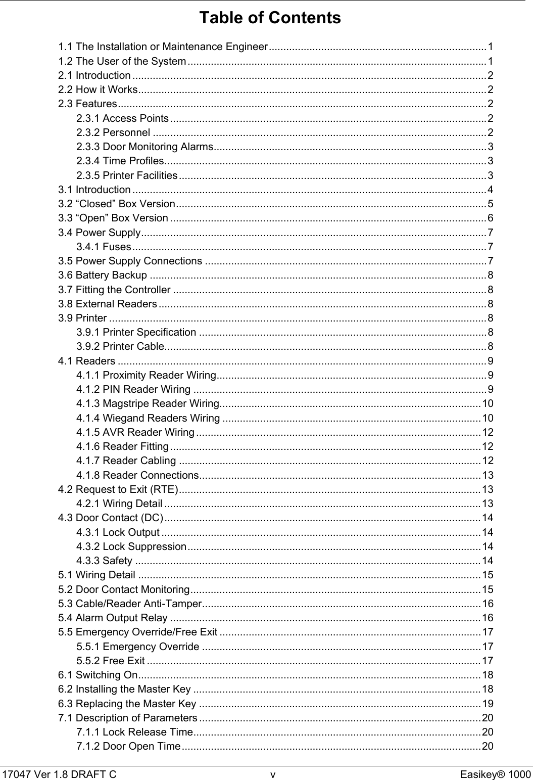
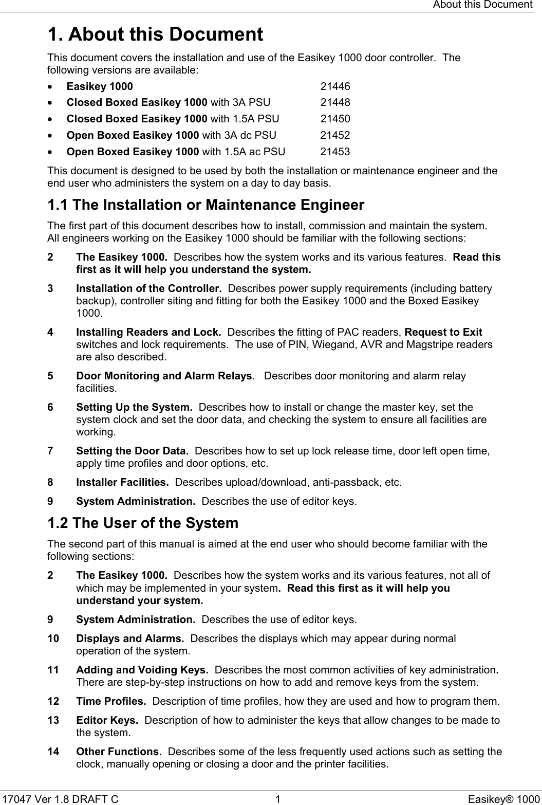
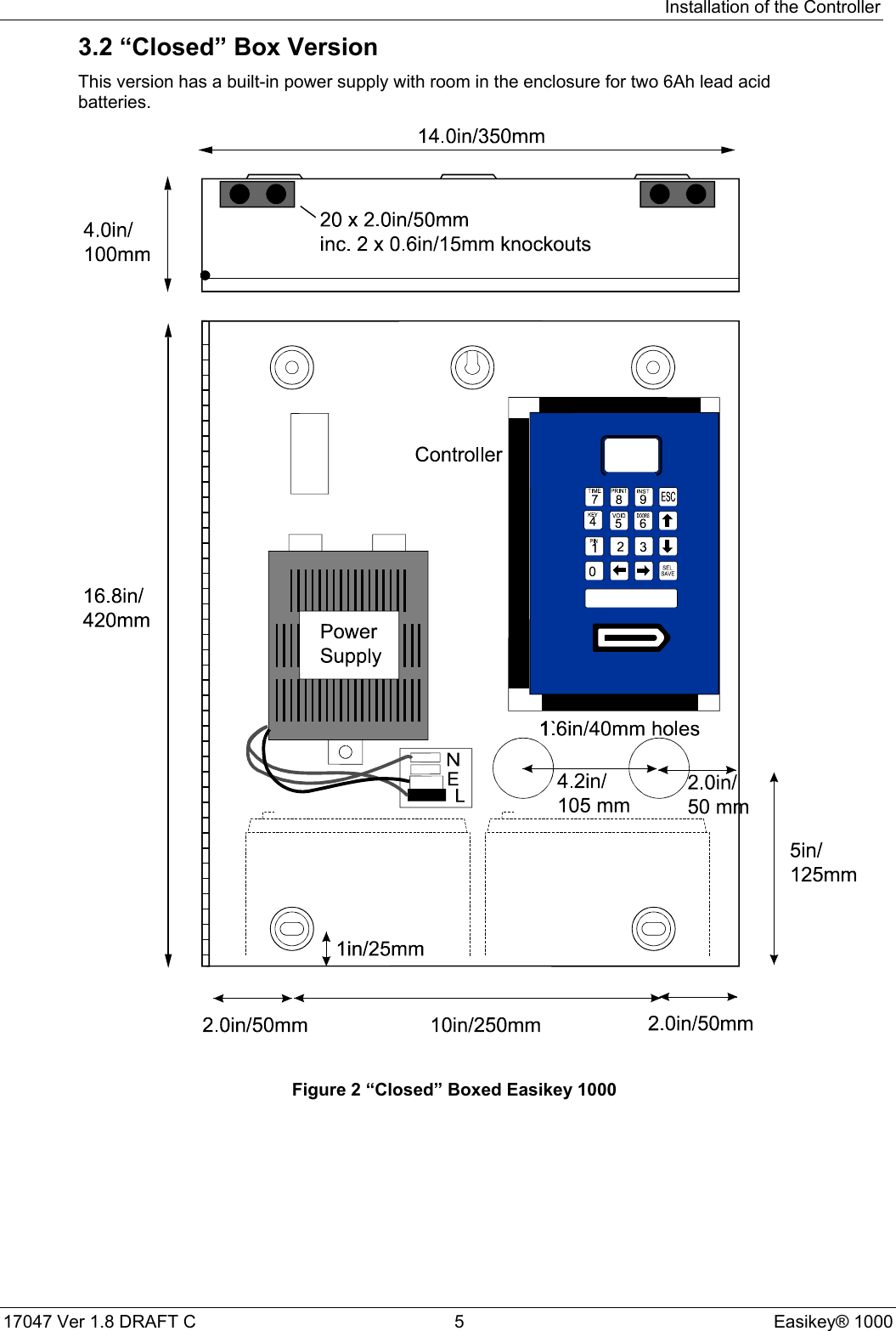
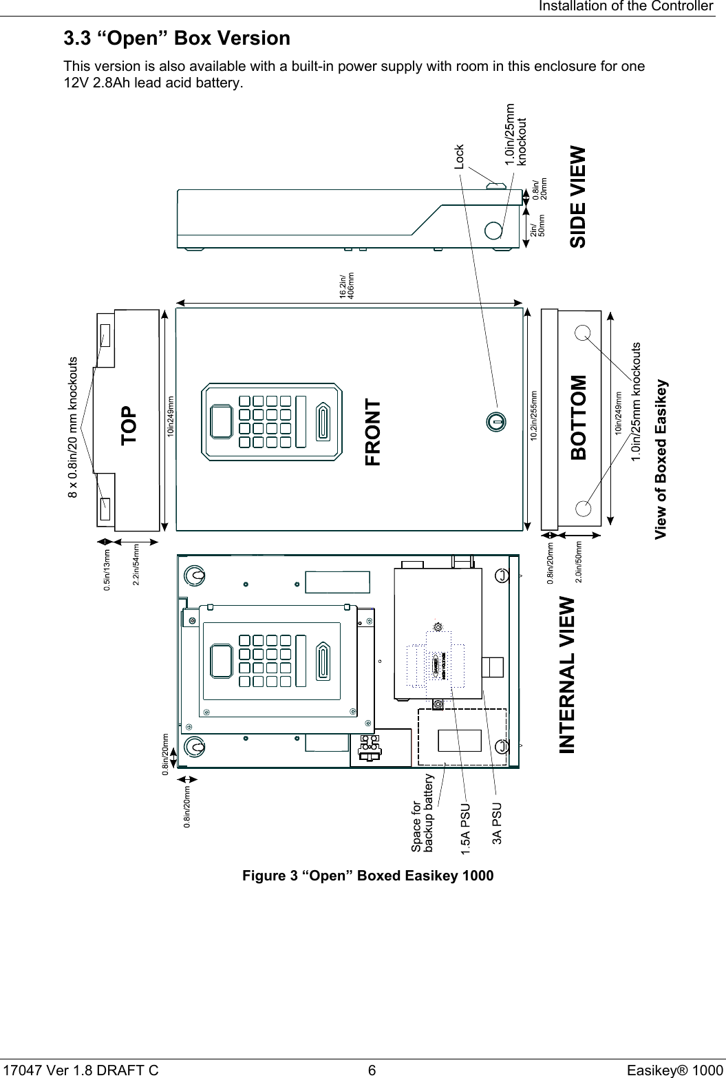
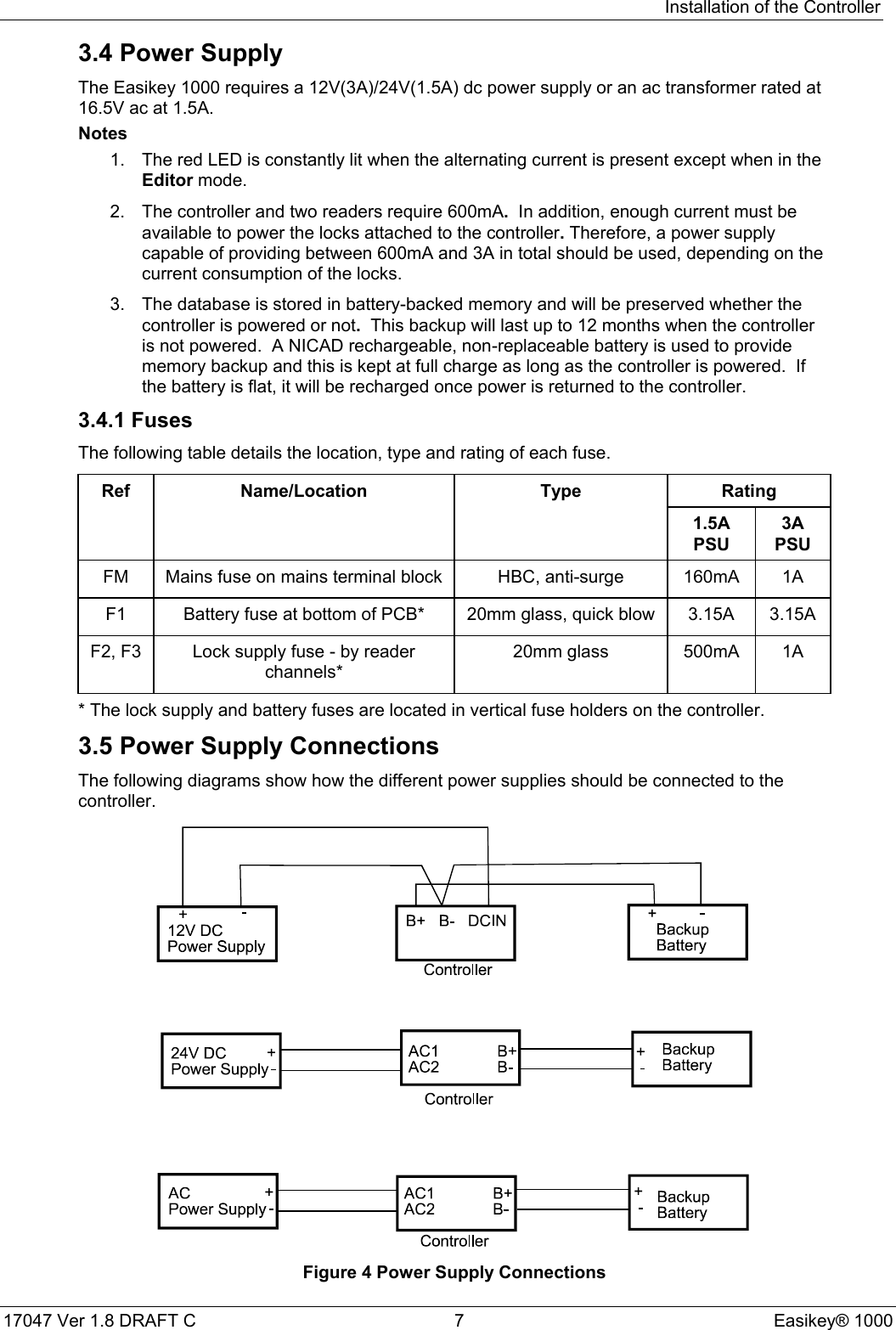
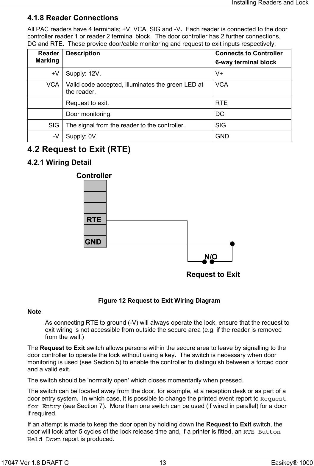
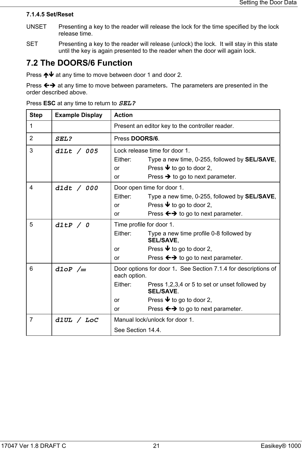
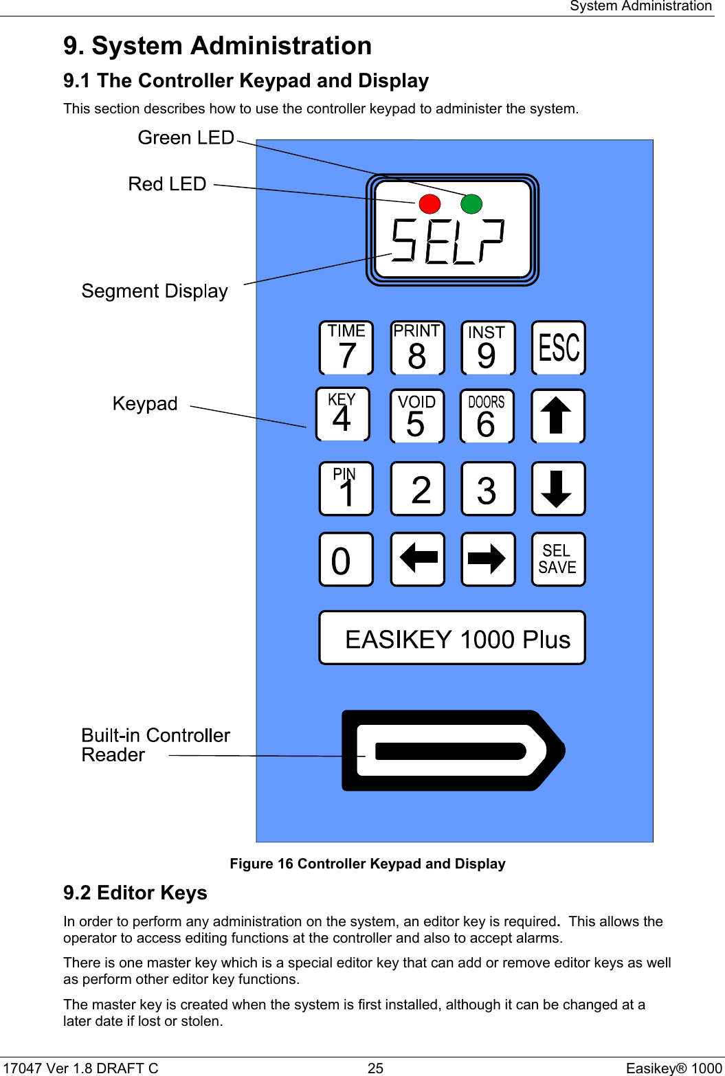
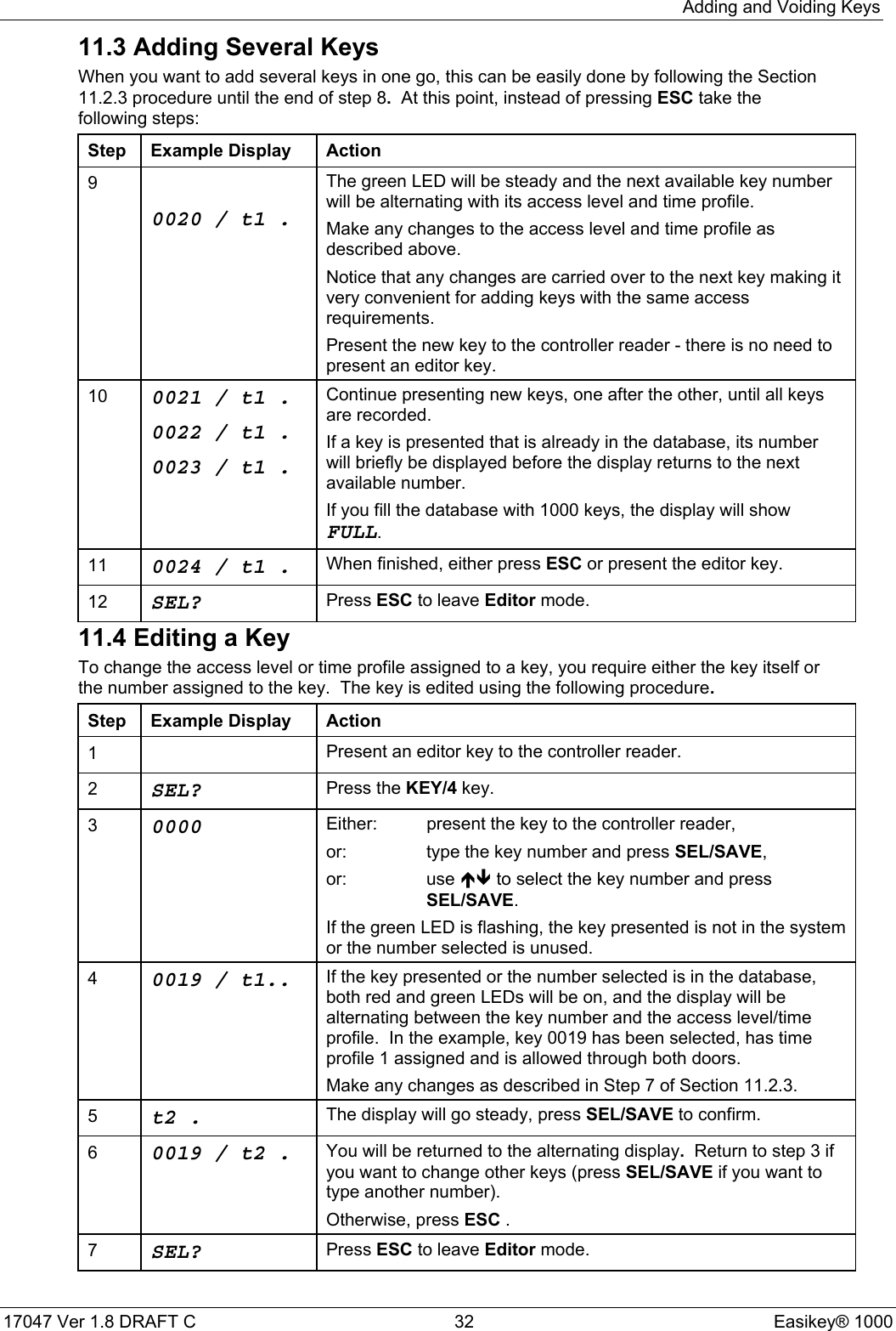
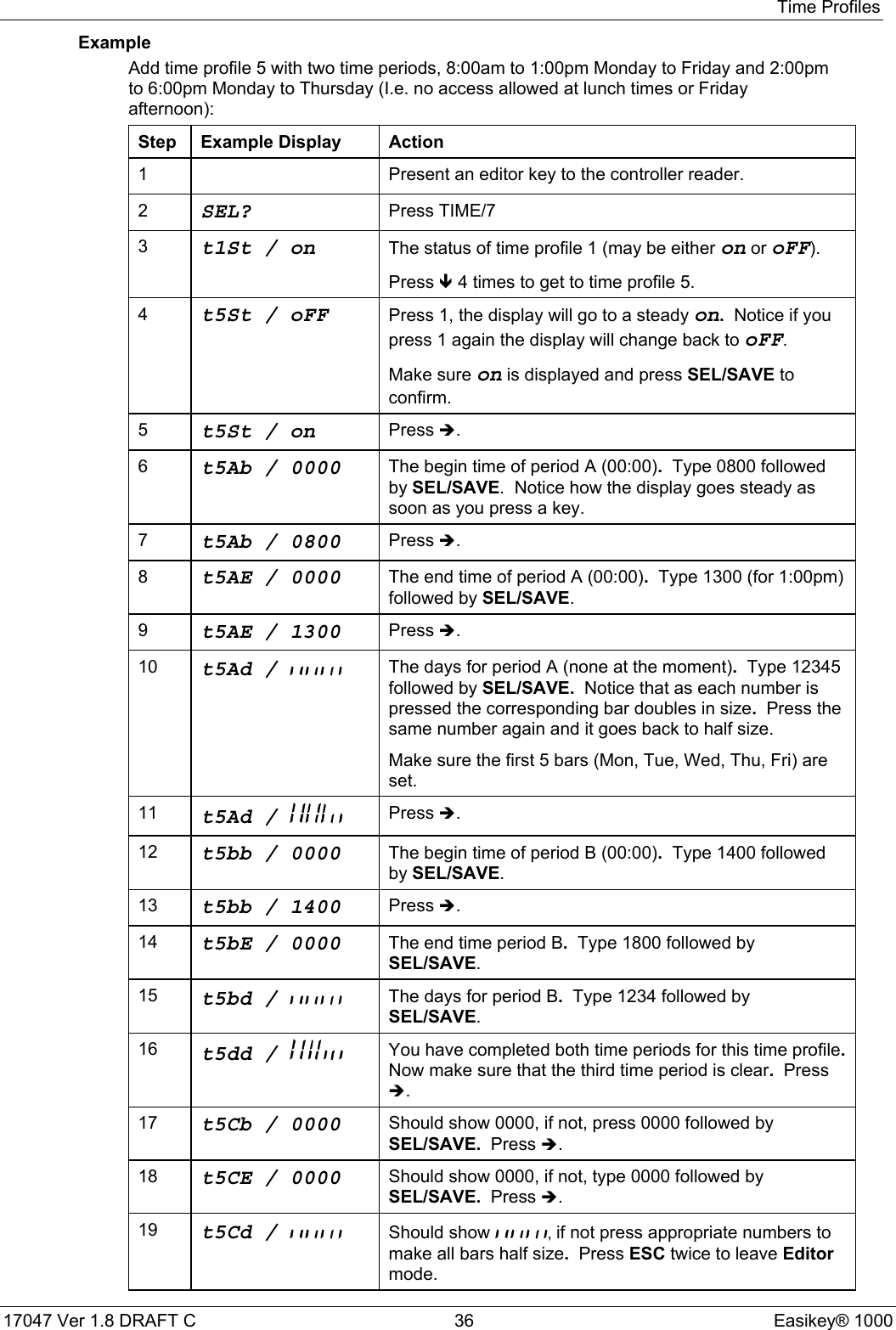
![Displays and Alarms17047 Ver 1.8 DRAFT C 27 Easikey® 100010. Displays and AlarmsThe Easikey 1000 door controller will display various characters on its 4-character screen andproduce a sound as a response to certain conditions. These are described below.Also included in this section are example printer reports produced when a printer is attached toan Easikey 1000.10.1 Power IndicatorsWhen not in Editor mode (to add/delete keys, etc.) the red and green LEDs are used as powerindicators as follows:• The red LED is constantly lit indicating that ac supply is healthy.• The green LED is constantly lit when the battery (if any) is low (less than 12V).These are not referred to elsewhere in the document and it is assumed that power is supplied tothe unit.10.2 Normal DisplaysWhen nothing is happening, the display is blank and no sounds are produced.Whenever a door is opened normally, either with a key or by using a Request to Exit switch,the display will show:Door 1 Open Door 2 Open Both Doors OpenPrinter ExampleDATE TIME DOOR USER TRANSACTION[0123] 12/06/95 10:34 1 0092 Access Authorised[0124] 12/06/95 10:35 2 Request to Exit[0125] 12/06/95 10:50 2 Manual Unlock[0126[ 12/06/95 13:30 1 Automatic Unlock10.3 Door Left Open WarningThis warning will only be given if door monitoring is being used - check with the installer of thesystem to see if this is the case.If a door is left open longer than the time set, the oP(shown above) will start to flash for theparticular door left open. The oP will continue to flash until the door is closed. There is nosound associated with this warning.Printer ExampleDATE TIME DOOR USER TRANSACTION[0233] 12/06/92 12:34 1 Door Left Open[0234] 12/06/92 12:35 1 Door Closed](https://usermanual.wiki/PAC/EK-1000P/User-Guide-294921-Page-35.png)
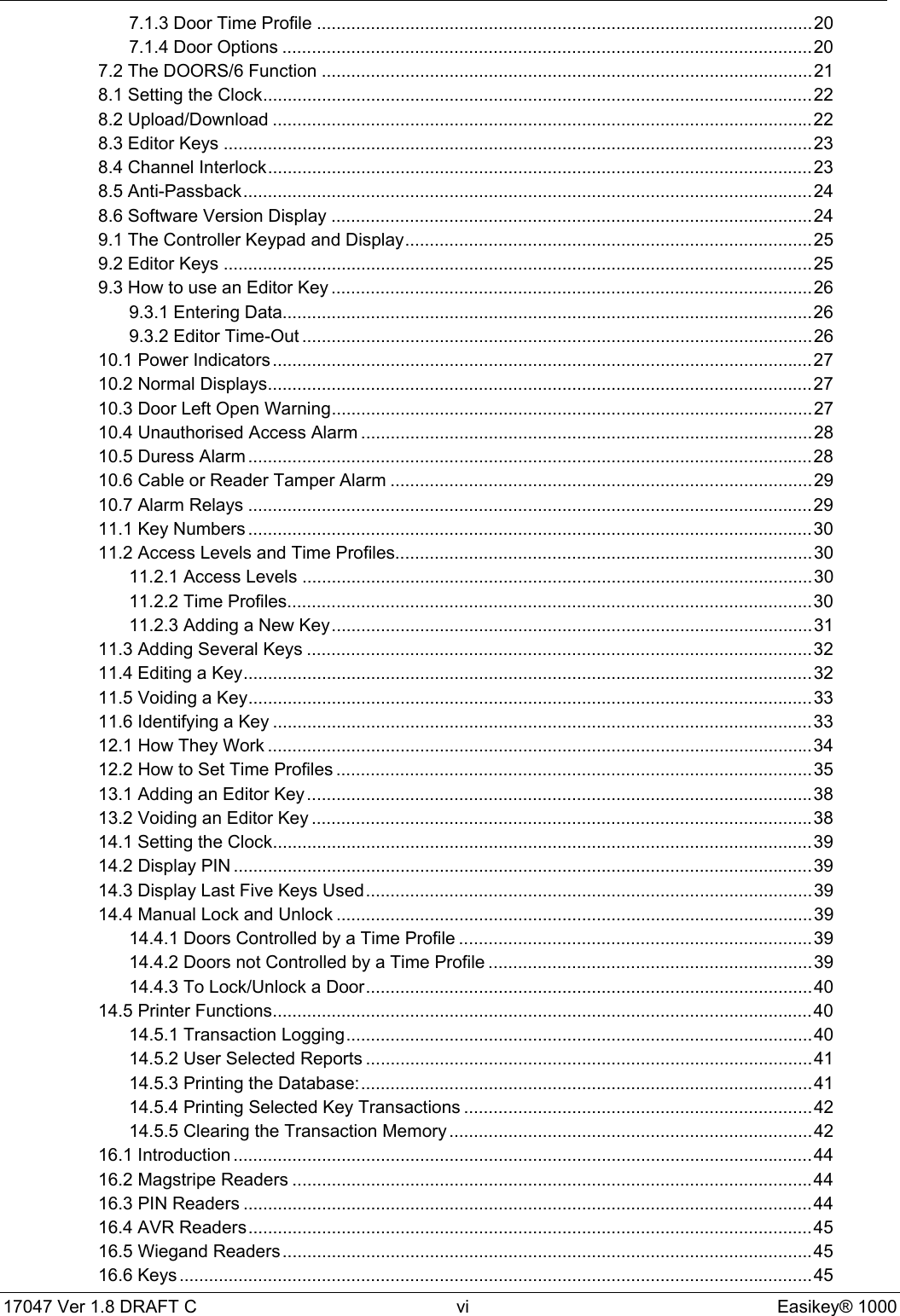
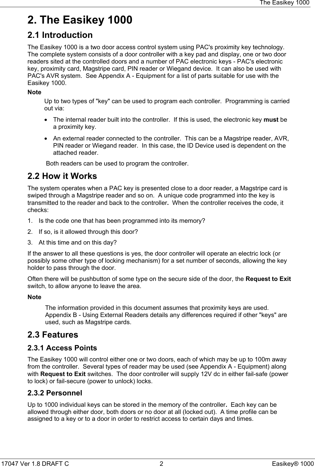
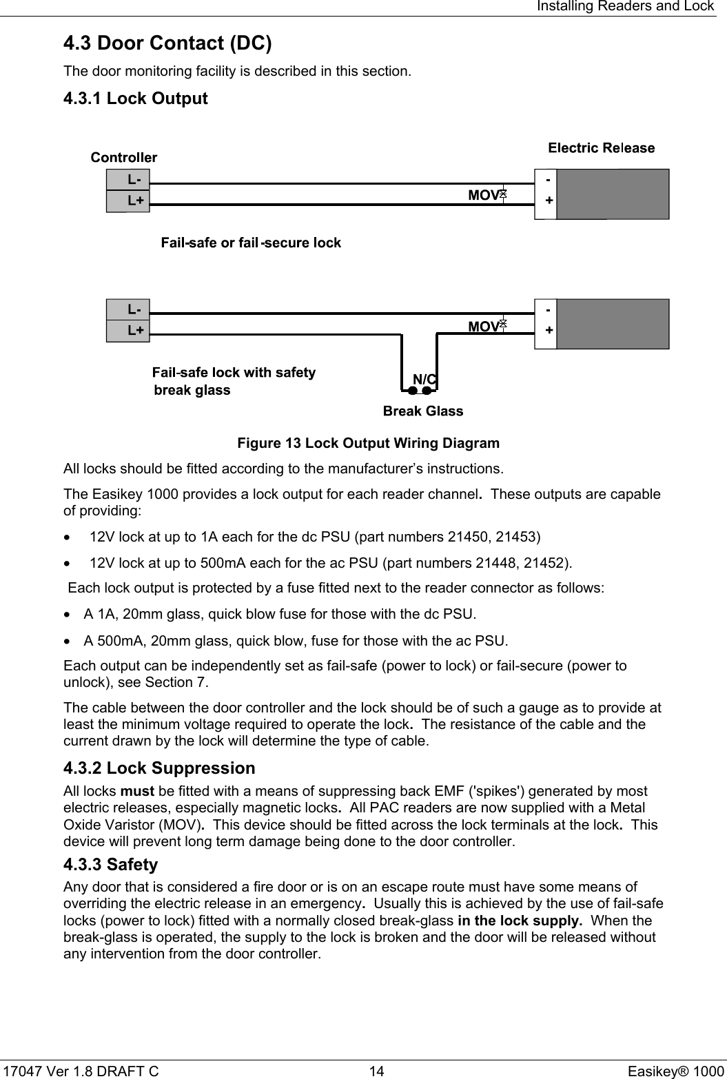
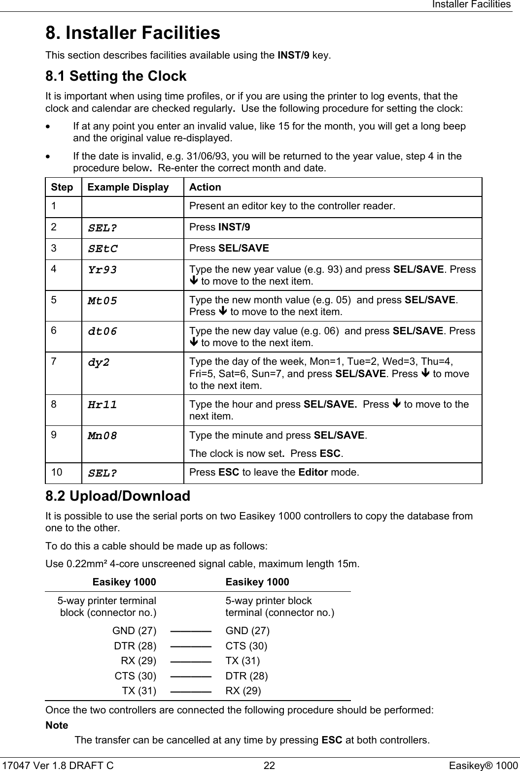
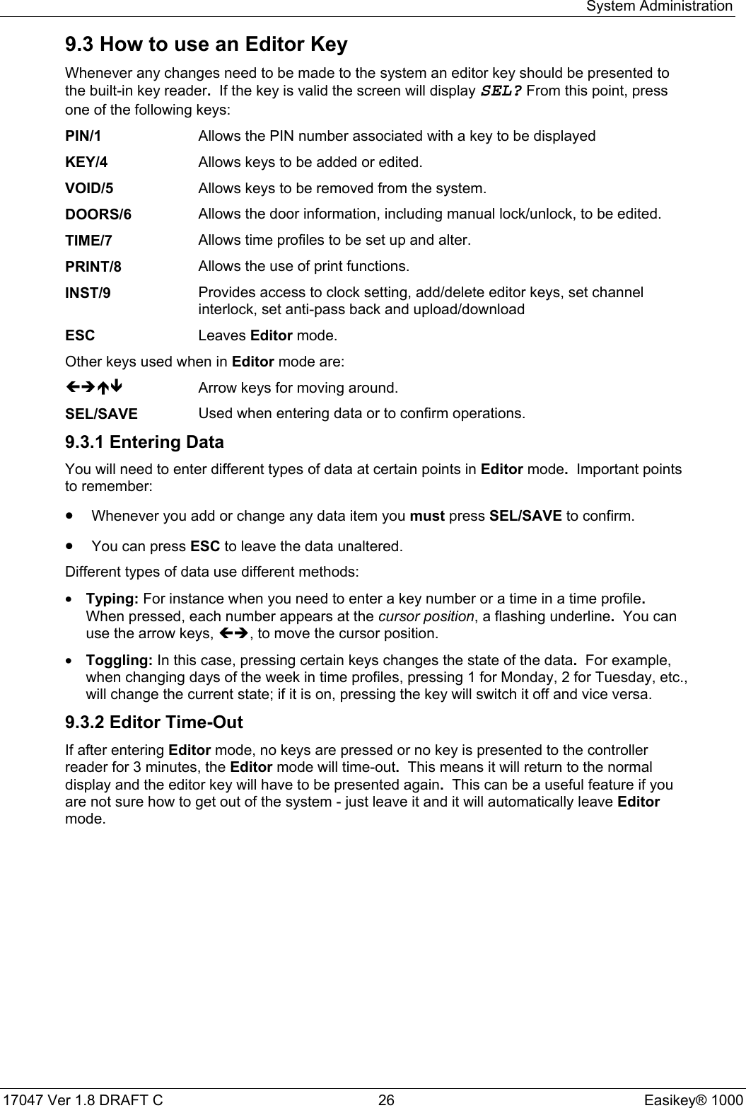
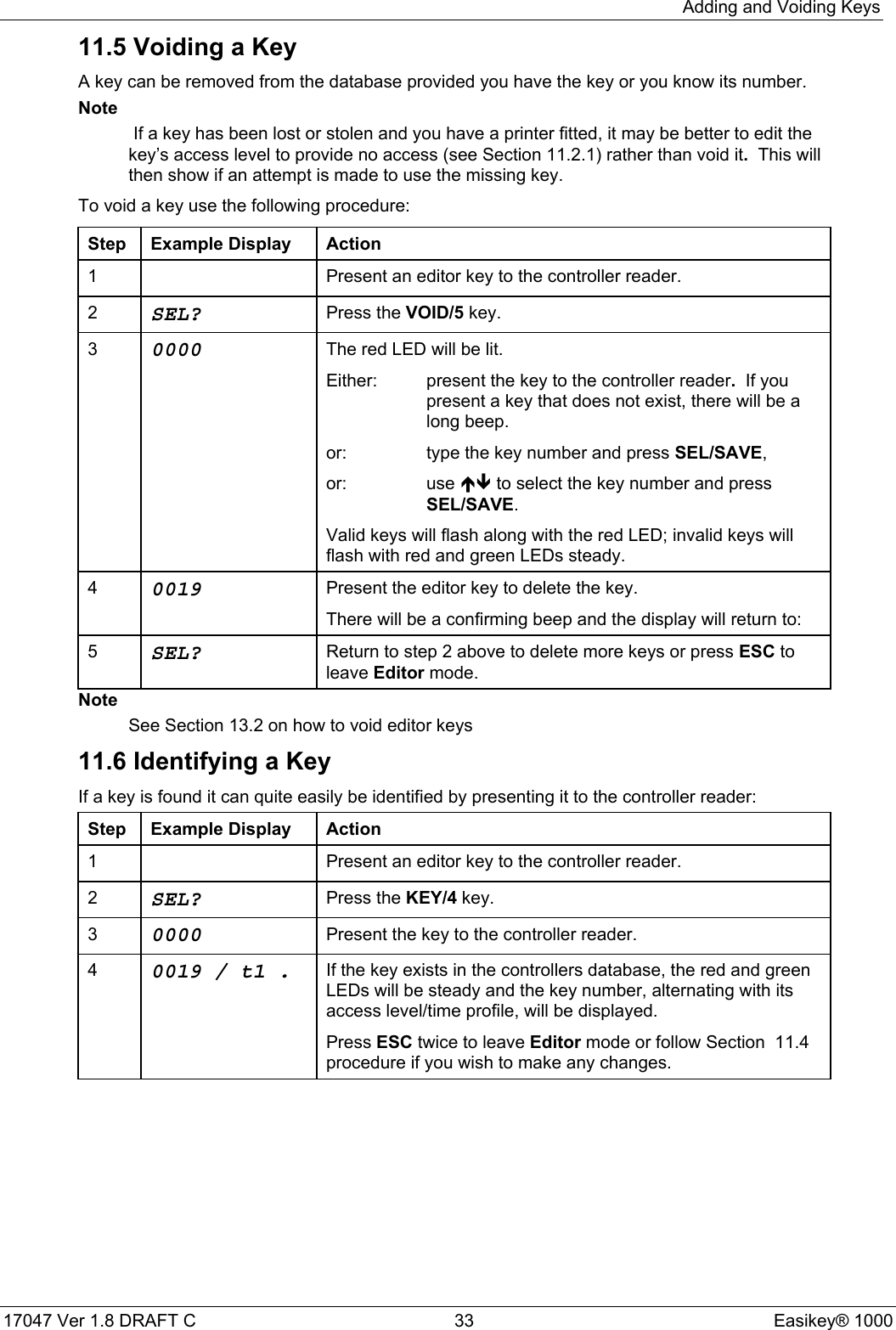
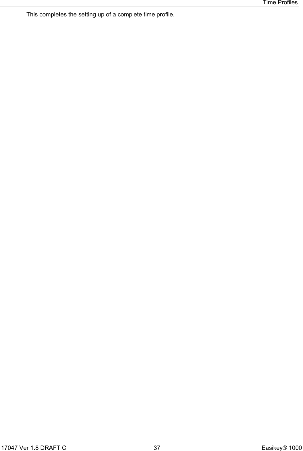
![Displays and Alarms17047 Ver 1.8 DRAFT C 28 Easikey® 100010.4 Unauthorised Access AlarmThis alarm will only be given if door monitoring is being used - check with the installer of thesystem to see if this is the case.If a door is opened without a key being used, time profile being active, manual unlock used or aRequest to Exit switch being pressed, the controller interprets this condition asUnauthorised Access. In this case, the alarm has to be accepted by presenting an editorkey to the controller reader.This alarm gives exactly the same displays and sounds as for Cable or Reader Tamperalarm (see Section 10.6). However, the printer report is different.Display AL, FlashingSound Every 2 secondsUnauthorised access or cable tamper.Present editor key to accept, the sound will stop.Display AL, SteadySound SilentAccepted alarm or cable/reader tamper.The alarm condition still exists, either the door is still open or thecable/reader is still tampered.Printer ExampleDATE TIME DOOR USER TRANSACTION[0278] 12/06/92 13:34 1 Unauthorised Access[0282] 12/06/92 13:35 1 MASTER Local Alarm Accepted[0285] 12/06/92 13:37 1 Alarm Cleared10.5 Duress AlarmThis alarm will only be given if a PIN reader is being used and the keyholder is forced to openthe door under duress. If the PIN is, for example, 1234, the keyholder may enter 1235 instead.This will open the door but send a code to the controller indicating that the door has beenopened under duress.The alarm generated at the controller is as follows:Display dU, FlashingSound Every 2 secondsPIN Code Duress.Present editor key to accept the alarm; the sound will stop anddisplay will clear.Printer ExampleDATE TIME DOOR USER TRANSACTION[0278] 12/06/92 13:34 1 PIN Code Duress[0282] 12/06/92 13:35 1 MASTER Local Alarm Accepted](https://usermanual.wiki/PAC/EK-1000P/User-Guide-294921-Page-36.png)
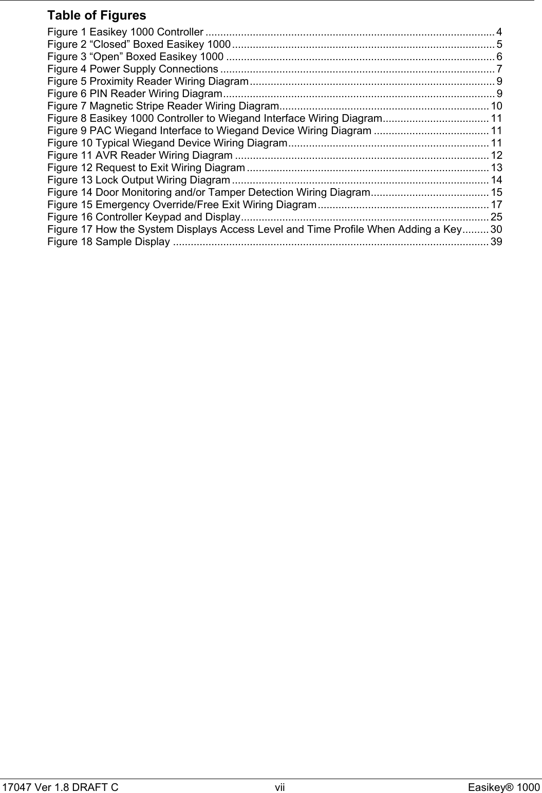
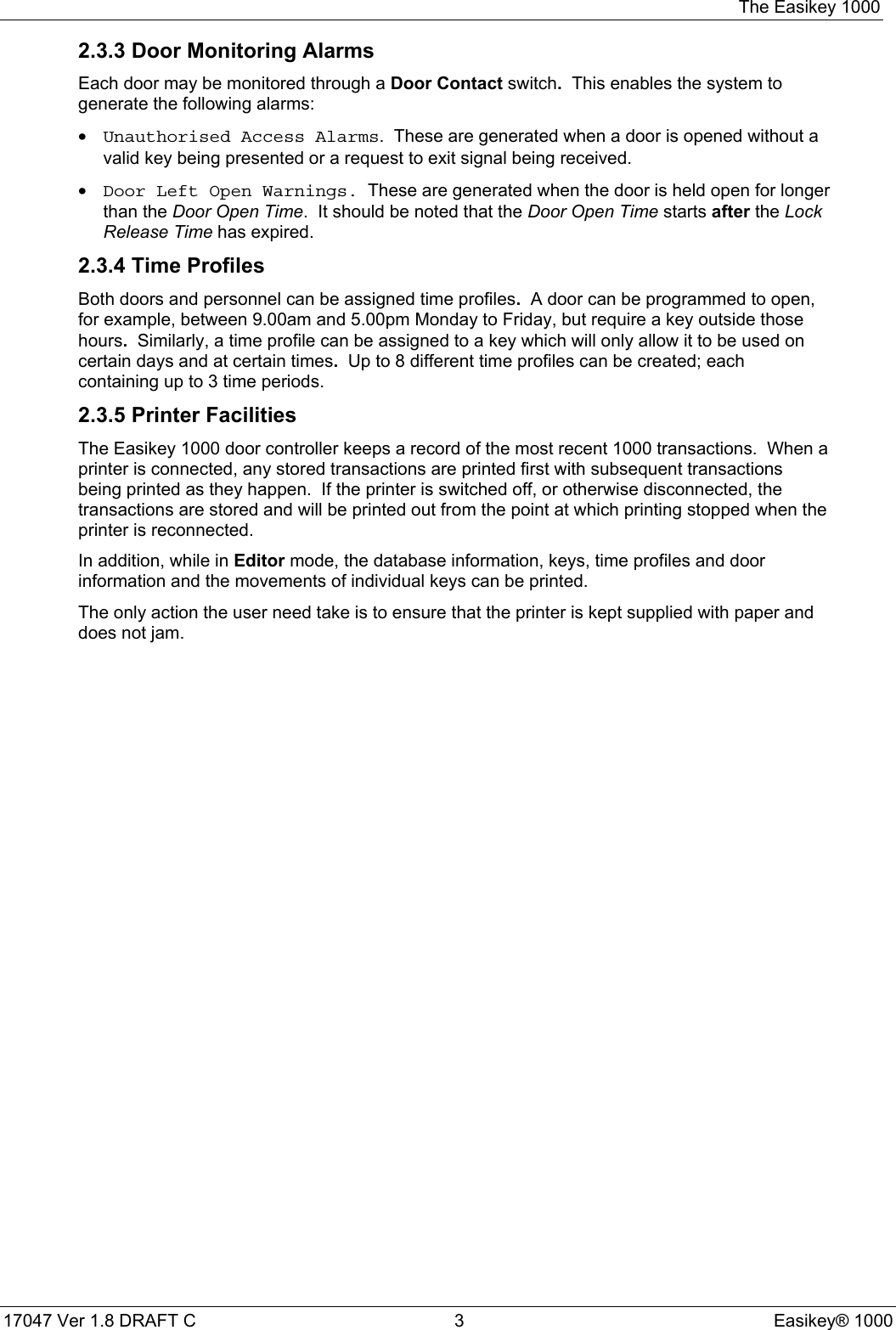
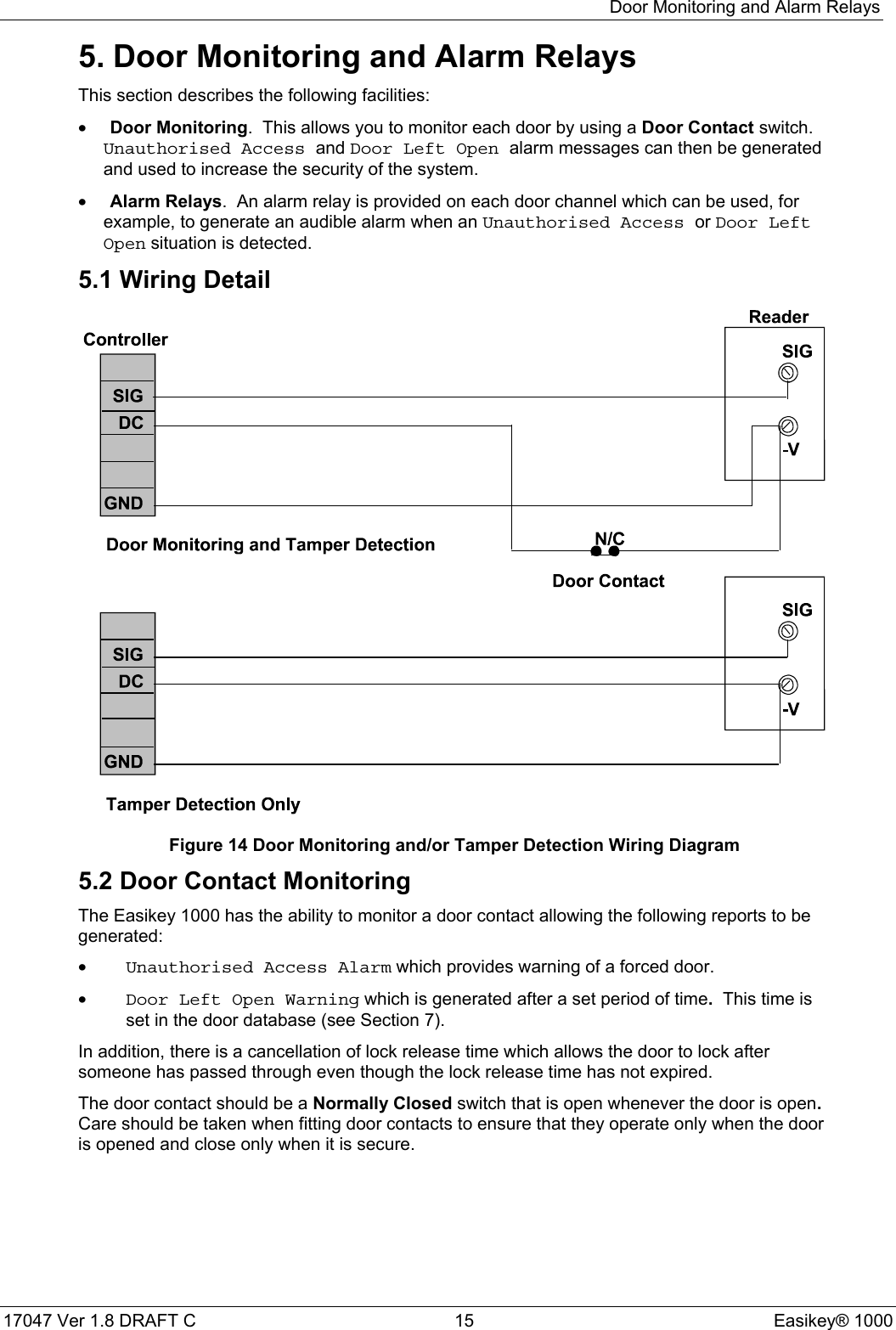
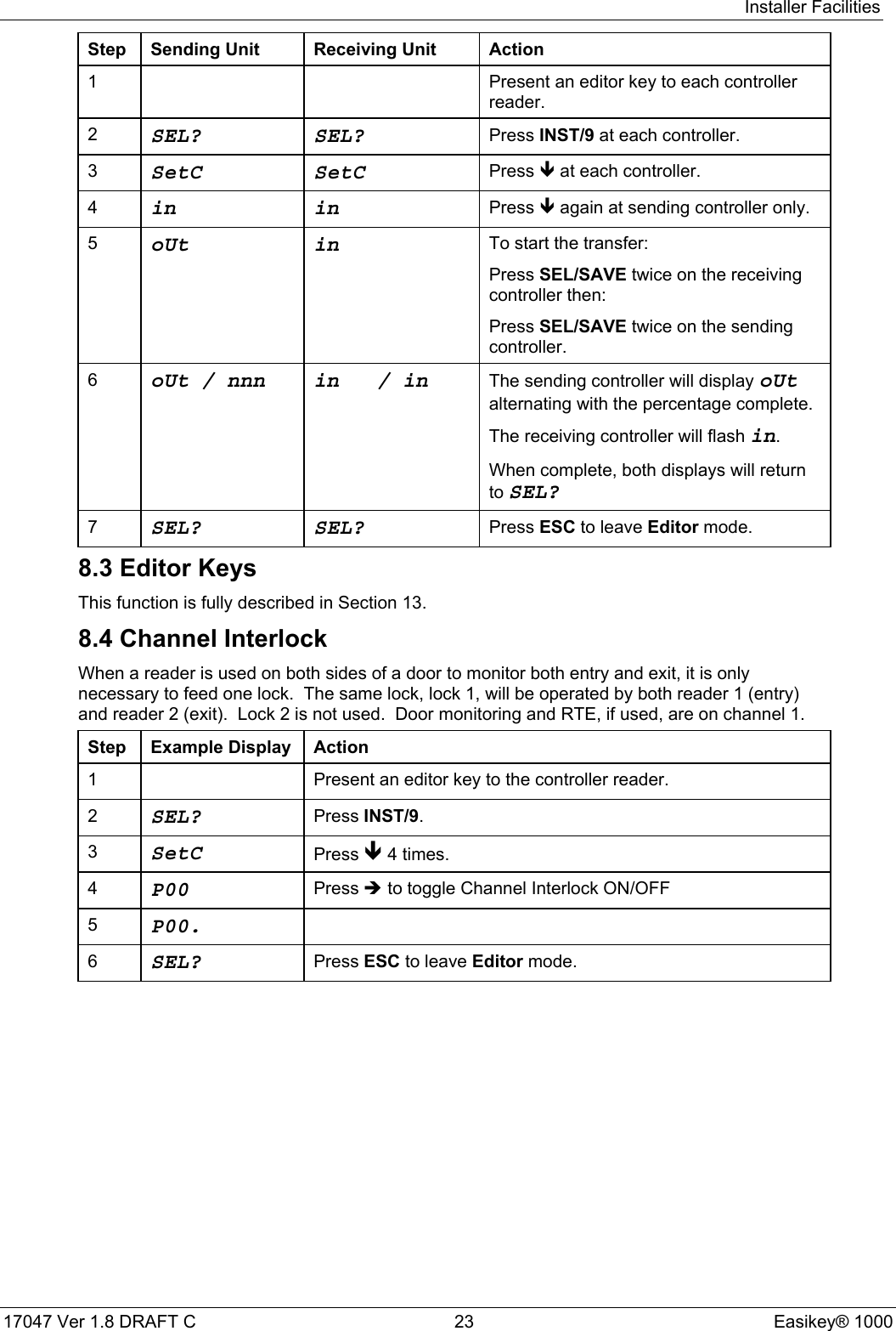
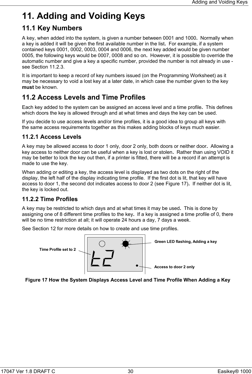
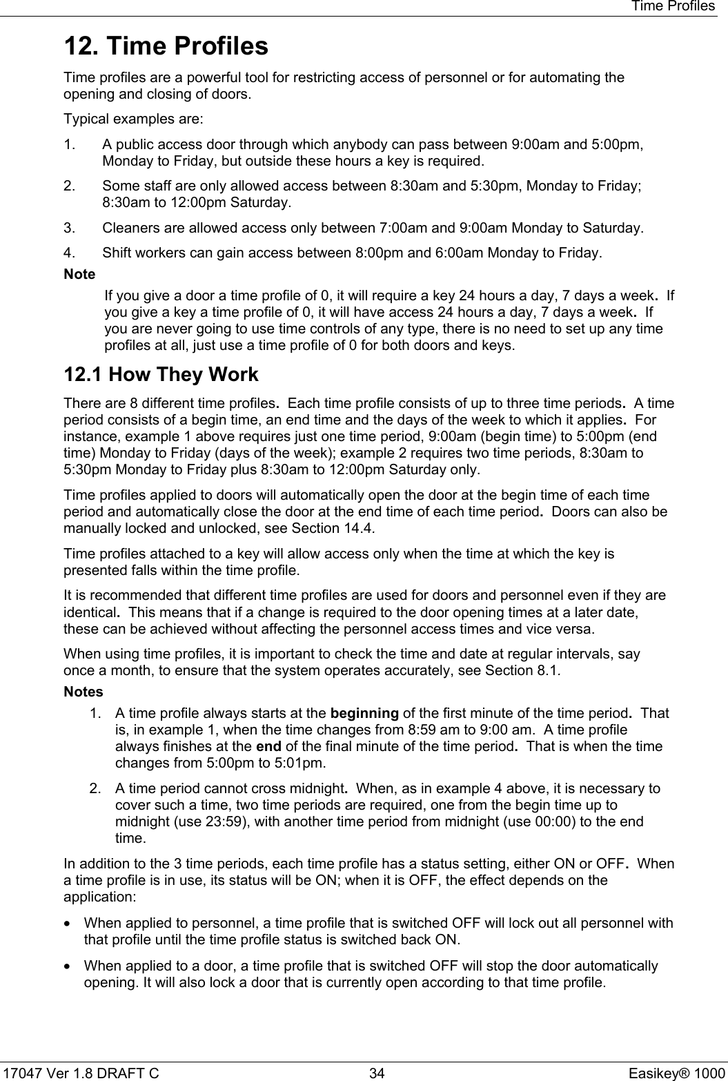
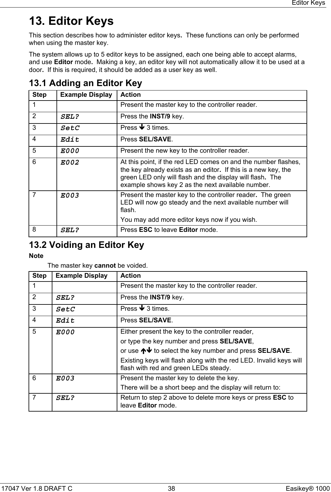
![Displays and Alarms17047 Ver 1.8 DRAFT C 29 Easikey® 100010.6 Cable or Reader Tamper AlarmThis alarm will only be given if the reader has been wired to detect this condition - check withthe installer of the system to see if this is the case.This alarm gives exactly the same displays and sounds as for Unauthorised Access alarm(see Section 10.4). However, the printer report is different.Printer ExampleDATE TIME DOOR USER TRANSACTION[0278] 12/06/92 13:34 1 Anti-tamper Alarm[0282] 12/06/92 13:35 1 EDITOR - 1 Local Alarm Accepted[0285] 12/06/92 13:37 1 Alarm Cleared10.7 Alarm RelaysIn the case of the Easikey 1000 alarms (Door Left Open, Unauthorised Access andCable or Reader Tamper), the alarm relays can be used to operate, for example, anaudible alarm such as a siren, etc.](https://usermanual.wiki/PAC/EK-1000P/User-Guide-294921-Page-37.png)
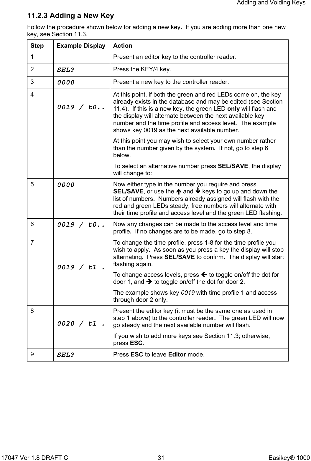
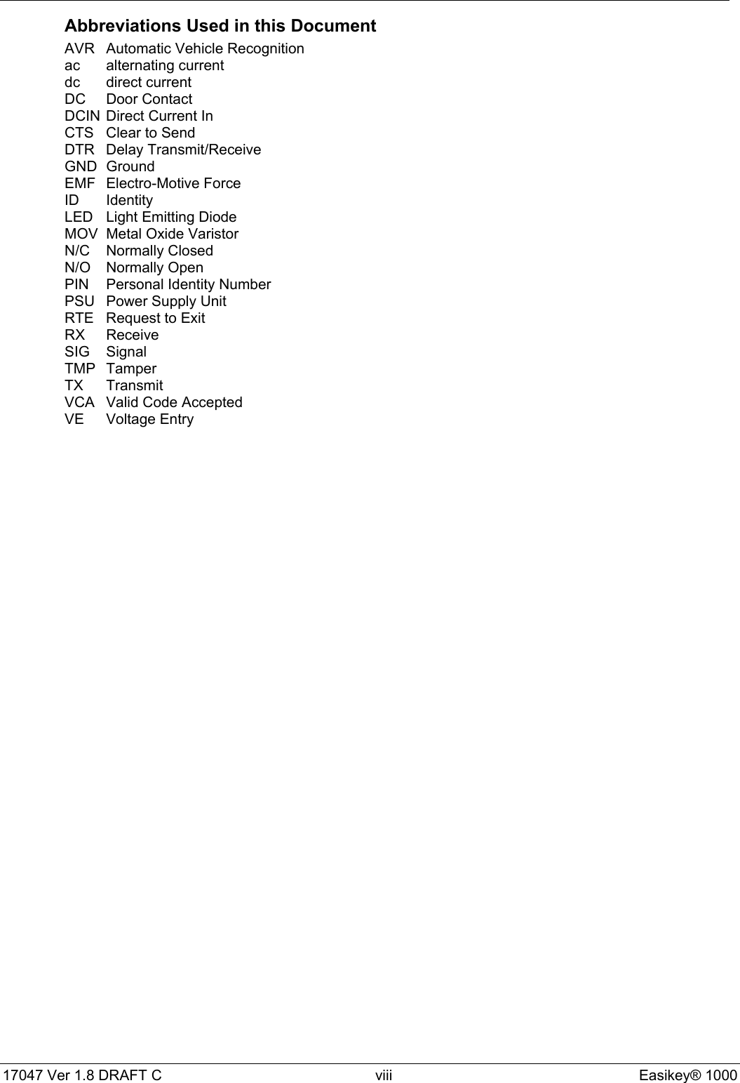
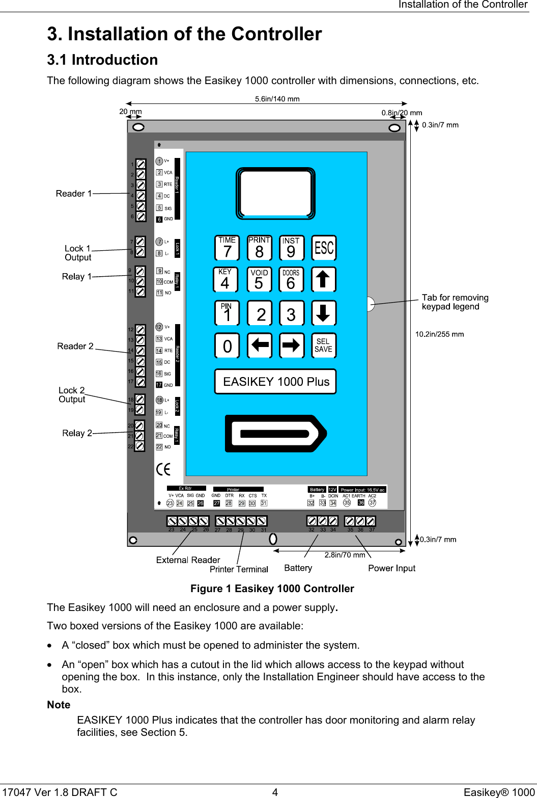
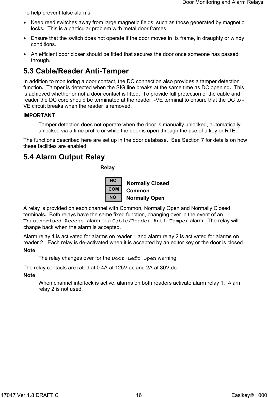
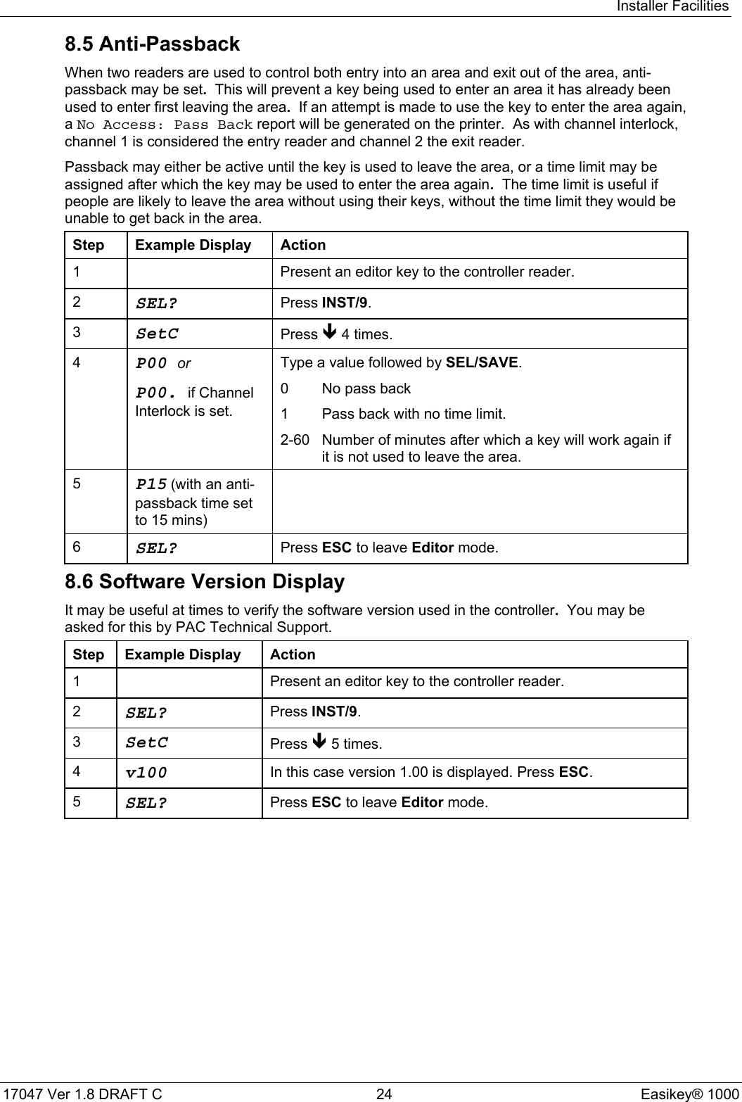
![Other Functions17047 Ver 1.8 DRAFT C 40 Easikey® 100014.4.3 To Lock/Unlock a DoorUse the following procedure to lock/unlock a door:Step Example Display Action1Present an editor key to the controller reader.2SEL? Press DOORS/6.3d1Lt / 0005 Press Î 4 times.4d1UL / Loc The display now shows the current state of door 1(Loc=locked, ULoC=unlocked).To lock/unlock, door 2 press Ð.5d1UL / Locord2UL / LocTo unlock a door, press 1 followed by SEL/SAVE, the displaywill change to ULoC and the door will unlock.To lock a door, press 0 followed by SEL/SAVE, the display willchange to LoC and the door will lock.Press ESC.6SEL? Press ESC to leave the Editor mode.14.5 Printer Functions14.5.1 Transaction LoggingAll Easikey 1000 door controllers keep a record of the most recent 1000 transactions, atransaction being any of the different types of event that may occur such as AccessAuthorised, Manual Lock, Automatic Lock, Editor On, etc. (see Appendix C -Transactionsfor details of all the different types of transaction).When a printer is connected, the controller will print these events as they happen. If the printeris switched off, or otherwise disconnected, the events will be stored and printed from the pointat which printing stopped when the printer is reconnected.The only action the user need take is to ensure that the printer is kept supplied with paper, doesnot jam, and make sure the paper flows freely through the printer.Sample Transaction PrintoutDATE TIME DOOR USER TRANSACTION 15/06/93[0054] 15/06/93 12:09 2 Door Left Open[0055] 15/06/93 12:10 2 Door Closed[0056] 15/06/93 12:14 1 0045 Access Authorised[0057] 15/06/93 12:14 2 0052 No Access: Level[0058] 15/06/93 12:15 EDITOR - 1 Editor On[0059] 15/06/93 12:17 EDITOR - 1 Editor Off[0060] 15/06/93 12:18 1 Request to Exit[0061] 15/06/93 12:19 1 0045 Access Authorised[0062] 15/06/93 12:23 1 0045 Access Authorised[0063] 15/06/93 12:30 1 Automatic Unlock[0064] 15/06/93 12:33 2 0120 No Access: Time[0065] 15/06/93 12:42 2 Unauthorised Access[0066] 15/06/93 12:43 2 MASTER Local Alarm Accepted[0067] 15/06/93 12:44 2 Alarm Cleared](https://usermanual.wiki/PAC/EK-1000P/User-Guide-294921-Page-48.png)
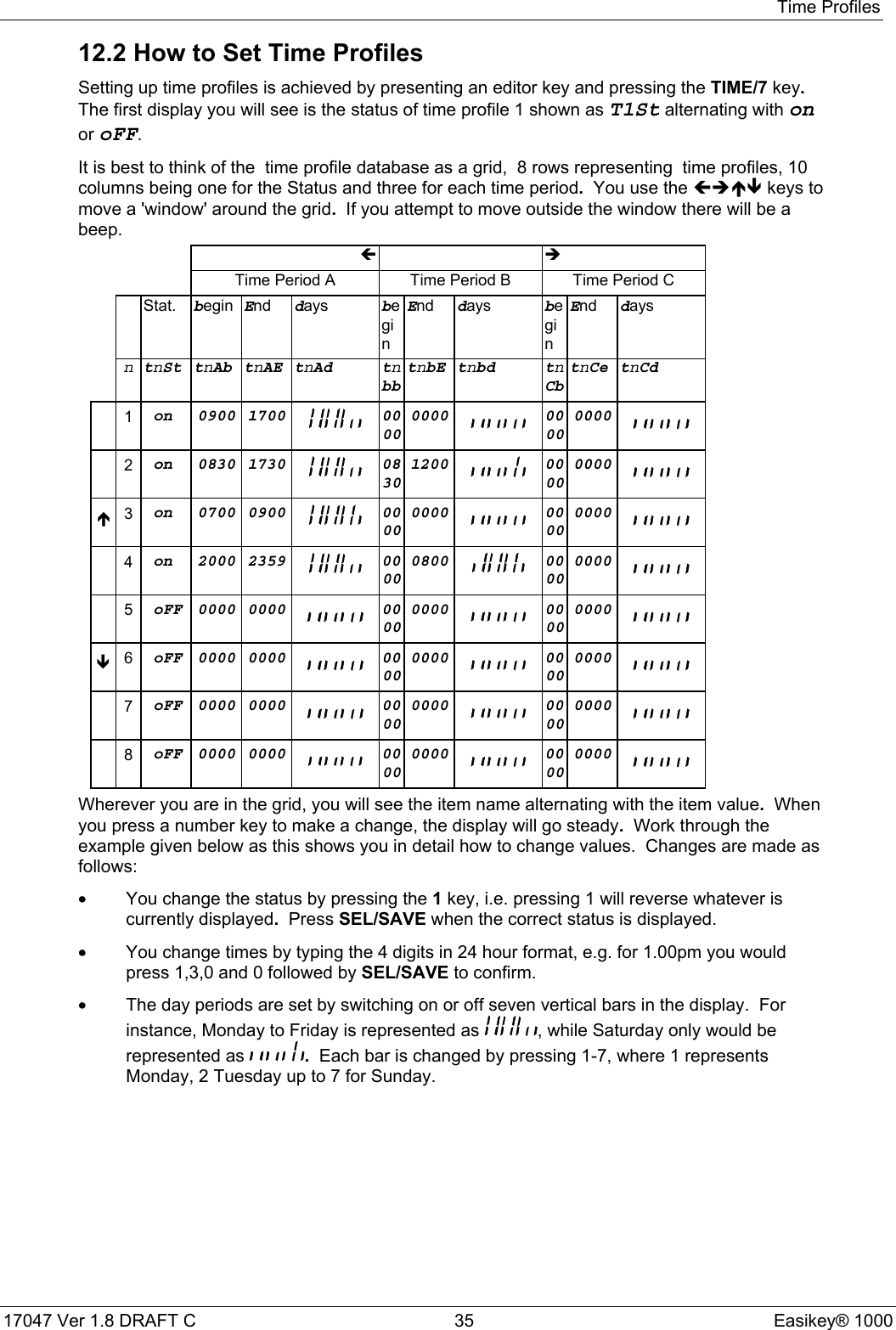
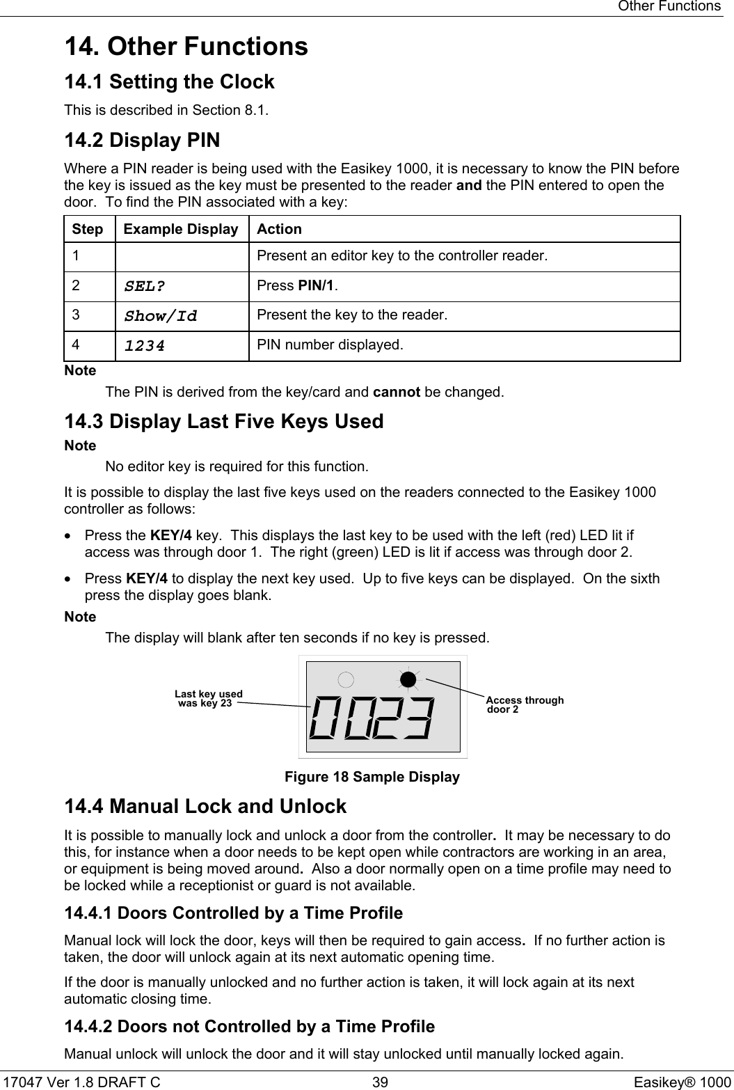
![Other Functions17047 Ver 1.8 DRAFT C 42 Easikey® 1000Door 2 LOCK TIME = 005DOOR TIME = 010TIME PROFILE = 0OPTIONS = Request to ExitDOOR = Locked14.5.4 Printing Selected Key TransactionsThis will print all the transactions associated with a particular key number currently in memory.The period of time this covers will depend on how long the system takes to generate 1000transactions.Press ESC to interrupt the printout.1 Present an editor key to the controller reader.2SEL? Press PRINT/8.3PrdA Press Ð.4Prtr Press SEL/SAVE.50000 Type the key number you require, press SEL/SAVE.There may be a short pause while the controller searchesthrough all the transactions.6tr /Prnt Printing transactions7SEL? Press ESC to leave Editor mode.Sample Transaction Printout for User 45Easikey 1000 SYSTEM PERSONNEL PRINTOUT 05/06/93 11:10 page 01DATE TIME DOOR USER TRANSACTION[0056] 05/06/93 12:14 1 0045 Access Authorised[0061] 05/06/93 12:19 1 0045 Access Authorised[0062] 05/06/93 12:23 1 0045 Access Authorised[0092] 05/06/93 12:30 2 0045 No Access: Level14.5.5 Clearing the Transaction MemoryThis is useful if no printer has been connected for some time and you do not want up to 1000old transactions to be printed.1 Present an editor key to the controller reader.2SEL? Press PRINT/8.3PrdA Press Ð.4Prtr Press Ð.5CLrt Press SEL/SAVE.6CLr /ALL? Press VOID/5 followed by SEL/SAVE to erase all transactionsfrom memory.There will be a short confirming beep.7SEL? Press ESC to leave the Editor mode.](https://usermanual.wiki/PAC/EK-1000P/User-Guide-294921-Page-50.png)