PAC EK-1000P Access controller with low range proximity reader User Manual 17047
PAC International Limited Access controller with low range proximity reader 17047
PAC >
Revised Manual

PAC INTERNATIONAL LTD, 1 Park Gate Close, Bredbury, Stockport, SK6 2SZ, England
Tel: +44 (0) 161 406 3400. Fax: +44 (0) 161 430 8658
www.pac.co.uk
Easikey® 1000
Installation and User Guide
17047 Ver 1.8 DRAFT C January 2003

17047 Ver 1.8 DRAFT C ii Easikey® 1000
Issue Record
Version Date Software Details
1.0 0ct 95 V1.0 Original Release
1.1 Nov 95 V1.0 Update PSU descriptions
1.2 Oct 96 V1.02 Changes to PCB and new boxed versions
1.3 Jun 98 V1.13 Updates to text and format
1.4 Apr 99 V1.13 Change to Personnel printout
1.5 Feb 00 V1.13 Updates to text, fuse rating updated
1.6 Nov 00 V1.13 Update to power supply diagram, 12V power supply to
reader, printer terminal block used for upload/download
1.7 Aug 01 V1.13 Easikey 1000 Plus note added, DCIN connector added to
Figure 1, 3A power supply on Figure 3, Figure 4 improved.
1.8 Jan 03 V1.13 RFID and FCC notices added

17047 Ver 1.8 DRAFT C iii Easikey® 1000
Version 1.8 January 2003
Changes are periodically made to the product, these changes will be incorporated into new
editions of this manual. PAC INTERNATIONAL LTD shall not be liable for errors contained
herein or for any consequential damages connected with the use of this material.
Copyright and Protective Notices
1. The copyright of this document and the associated drawings is the property of PAC
INTERNATIONAL LTD, and is issued on condition that it is not copied, reprinted or
reproduced, nor its contents disclosed, either wholly or in part, without the consent in writing
of, or in accordance with the conditions of a contract with PAC INTERNATIONAL LTD.
2. The publication of information in this document does not imply freedom from patent or other
protective rights of PAC INTERNATIONAL LTD, or others.
3. Performance figures and data quoted in this document are typical, and must be specifically
confirmed by PAC INTERNATIONAL LTD before they become applicable to any tender,
order or contract.
Trademarks
Easikey® is a registered trademark of PAC INTERNATIONAL LTD.
Training and Technical Support
Training courses covering the installation and use of all PAC products are regularly held at
PAC INTERNATIONAL LTD, Stockport. For further information on course availability, or to
discuss your specific requirements, contact the Training Manager at the address below.
It is strongly recommended that any persons installing or commissioning PAC products
attend a suitable training course beforehand.
Technical Support for all PAC products is available during normal office hours:
8:00am to 6:00pm Monday to Friday, excluding public holidays.
Tel: 0161 406 3400 International +44 161 406 3400
Fax: 0161 430 8658 International +44 161 430 8658
This service is provided primarily for the use of trained engineers. End users of PAC products
should first of all contact their installation or maintenance company before contacting PAC.
PAC INTERNATIONAL LTD
1 Park Gate Close
Bredbury
Stockport
SK6 2SZ
England
17047 Ver 1.8 DRAFT C iv Easikey® 1000
IMPORTANT:
When installing the PAC equipment the following should be noted:
HEALTH AND SAFETY
Installation must wired in accordance with National Wiring Regulations (BS7671, IEE
National Wiring Regulations in the UK). Failure to do so can result in injury or death by
electric shock.
It must also comply with any local Fire, Health and Safety regulations. A secured door
that may be part of an escape route from an area must be fitted with:
•A fail-safe lock (A). So that the door will be released if the power fails. Ideally a
magnetic lock should be used as these are less likely to jam or seize.
•A normally-closed break-glass or manual pull (B) in the lock supply wiring. So that in
an emergency the fail-safe lock can be immediately depowered.
B
A
The controller must be earthed.
Isolate the controller supply before working on the controller.
CABLING
The cabling used in the PAC Access Control Systems (six wire bus, reader cables, etc.) are not
prone to electrical interference. However, you should avoid routing cable close to heavy load
switching cables and equipment. If this is unavoidable, cross the cable at right angles every
3.3-6.6ft/1-2m to reduce the interference.
RFID Devices
As similar RFID technology is now widely used in a number of other industries, for example
automotive immobilisers, it is possible that interaction between your access control ID and other
devices may cause one or the other to function incorrectly. Should you suspect that you have
experienced such a problem the solution is to separate your access control ID from other RFID
devices.
FCC Notice
This device complies with part 15 of the FCC rules. Operation is subject to the following two
conditions (1) this device may not cause harmful interference, and (2) this device must accept
any interference received, including interference that may cause undesired operation.
FCC ID OQL-EK-1000P
Changes or modifications not expressly approved by the party responsible for compliance could
void the user's authority to operate the equipment.
Note
This equipment has been tested and found to comply with the limits for a Class A digital
device, pursuant to part 15 of the FCC Rules. These limits are designed to provide
reasonable protection against harmful interference when the equipment is operated in a
commercial environment. This equipment generates, uses, and can radiate radio
frequency energy and, if not installed and used in accordance with the instruction
manual, may cause harmful interference to radio communications. Operation of this
equipment in a residential area is likely to cause harmful interference in which case the
user will be required to correct the interference at his own expense.

17047 Ver 1.8 DRAFT C v Easikey® 1000
Table of Contents
1.1 The Installation or Maintenance Engineer...........................................................................1
1.2 The User of the System.......................................................................................................1
2.1 Introduction ..........................................................................................................................2
2.2 How it Works........................................................................................................................2
2.3 Features...............................................................................................................................2
2.3.1 Access Points .............................................................................................................2
2.3.2 Personnel ...................................................................................................................2
2.3.3 Door Monitoring Alarms..............................................................................................3
2.3.4 Time Profiles...............................................................................................................3
2.3.5 Printer Facilities..........................................................................................................3
3.1 Introduction ..........................................................................................................................4
3.2 “Closed” Box Version...........................................................................................................5
3.3 “Open” Box Version .............................................................................................................6
3.4 Power Supply.......................................................................................................................7
3.4.1 Fuses..........................................................................................................................7
3.5 Power Supply Connections .................................................................................................7
3.6 Battery Backup ....................................................................................................................8
3.7 Fitting the Controller ............................................................................................................8
3.8 External Readers .................................................................................................................8
3.9 Printer ..................................................................................................................................8
3.9.1 Printer Specification ...................................................................................................8
3.9.2 Printer Cable...............................................................................................................8
4.1 Readers ...............................................................................................................................9
4.1.1 Proximity Reader Wiring.............................................................................................9
4.1.2 PIN Reader Wiring .....................................................................................................9
4.1.3 Magstripe Reader Wiring..........................................................................................10
4.1.4 Wiegand Readers Wiring .........................................................................................10
4.1.5 AVR Reader Wiring ..................................................................................................12
4.1.6 Reader Fitting...........................................................................................................12
4.1.7 Reader Cabling ........................................................................................................12
4.1.8 Reader Connections.................................................................................................13
4.2 Request to Exit (RTE)........................................................................................................13
4.2.1 Wiring Detail .............................................................................................................13
4.3 Door Contact (DC).............................................................................................................14
4.3.1 Lock Output ..............................................................................................................14
4.3.2 Lock Suppression.....................................................................................................14
4.3.3 Safety .......................................................................................................................14
5.1 Wiring Detail ......................................................................................................................15
5.2 Door Contact Monitoring....................................................................................................15
5.3 Cable/Reader Anti-Tamper................................................................................................16
5.4 Alarm Output Relay ...........................................................................................................16
5.5 Emergency Override/Free Exit ..........................................................................................17
5.5.1 Emergency Override ................................................................................................17
5.5.2 Free Exit ...................................................................................................................17
6.1 Switching On......................................................................................................................18
6.2 Installing the Master Key ...................................................................................................18
6.3 Replacing the Master Key .................................................................................................19
7.1 Description of Parameters .................................................................................................20
7.1.1 Lock Release Time...................................................................................................20
7.1.2 Door Open Time.......................................................................................................20

17047 Ver 1.8 DRAFT C vi Easikey® 1000
7.1.3 Door Time Profile .....................................................................................................20
7.1.4 Door Options ............................................................................................................20
7.2 The DOORS/6 Function ....................................................................................................21
8.1 Setting the Clock................................................................................................................22
8.2 Upload/Download ..............................................................................................................22
8.3 Editor Keys ........................................................................................................................23
8.4 Channel Interlock...............................................................................................................23
8.5 Anti-Passback....................................................................................................................24
8.6 Software Version Display ..................................................................................................24
9.1 The Controller Keypad and Display...................................................................................25
9.2 Editor Keys ........................................................................................................................25
9.3 How to use an Editor Key ..................................................................................................26
9.3.1 Entering Data............................................................................................................26
9.3.2 Editor Time-Out ........................................................................................................26
10.1 Power Indicators ..............................................................................................................27
10.2 Normal Displays...............................................................................................................27
10.3 Door Left Open Warning..................................................................................................27
10.4 Unauthorised Access Alarm ............................................................................................28
10.5 Duress Alarm ...................................................................................................................28
10.6 Cable or Reader Tamper Alarm ......................................................................................29
10.7 Alarm Relays ...................................................................................................................29
11.1 Key Numbers ...................................................................................................................30
11.2 Access Levels and Time Profiles.....................................................................................30
11.2.1 Access Levels ........................................................................................................30
11.2.2 Time Profiles...........................................................................................................30
11.2.3 Adding a New Key..................................................................................................31
11.3 Adding Several Keys .......................................................................................................32
11.4 Editing a Key....................................................................................................................32
11.5 Voiding a Key...................................................................................................................33
11.6 Identifying a Key ..............................................................................................................33
12.1 How They Work ...............................................................................................................34
12.2 How to Set Time Profiles .................................................................................................35
13.1 Adding an Editor Key.......................................................................................................38
13.2 Voiding an Editor Key ......................................................................................................38
14.1 Setting the Clock..............................................................................................................39
14.2 Display PIN ......................................................................................................................39
14.3 Display Last Five Keys Used...........................................................................................39
14.4 Manual Lock and Unlock .................................................................................................39
14.4.1 Doors Controlled by a Time Profile ........................................................................39
14.4.2 Doors not Controlled by a Time Profile ..................................................................39
14.4.3 To Lock/Unlock a Door...........................................................................................40
14.5 Printer Functions..............................................................................................................40
14.5.1 Transaction Logging...............................................................................................40
14.5.2 User Selected Reports ...........................................................................................41
14.5.3 Printing the Database:............................................................................................41
14.5.4 Printing Selected Key Transactions .......................................................................42
14.5.5 Clearing the Transaction Memory ..........................................................................42
16.1 Introduction ......................................................................................................................44
16.2 Magstripe Readers ..........................................................................................................44
16.3 PIN Readers ....................................................................................................................44
16.4 AVR Readers...................................................................................................................45
16.5 Wiegand Readers............................................................................................................45
16.6 Keys .................................................................................................................................45

17047 Ver 1.8 DRAFT C vii Easikey® 1000
Table of Figures
Figure 1 Easikey 1000 Controller .................................................................................................. 4
Figure 2 “Closed” Boxed Easikey 1000......................................................................................... 5
Figure 3 “Open” Boxed Easikey 1000 ........................................................................................... 6
Figure 4 Power Supply Connections ............................................................................................. 7
Figure 5 Proximity Reader Wiring Diagram................................................................................... 9
Figure 6 PIN Reader Wiring Diagram............................................................................................ 9
Figure 7 Magnetic Stripe Reader Wiring Diagram....................................................................... 10
Figure 8 Easikey 1000 Controller to Wiegand Interface Wiring Diagram.................................... 11
Figure 9 PAC Wiegand Interface to Wiegand Device Wiring Diagram ....................................... 11
Figure 10 Typical Wiegand Device Wiring Diagram.................................................................... 11
Figure 11 AVR Reader Wiring Diagram ...................................................................................... 12
Figure 12 Request to Exit Wiring Diagram .................................................................................. 13
Figure 13 Lock Output Wiring Diagram ....................................................................................... 14
Figure 14 Door Monitoring and/or Tamper Detection Wiring Diagram........................................ 15
Figure 15 Emergency Override/Free Exit Wiring Diagram.......................................................... 17
Figure 16 Controller Keypad and Display.................................................................................... 25
Figure 17 How the System Displays Access Level and Time Profile When Adding a Key......... 30
Figure 18 Sample Display ........................................................................................................... 39

17047 Ver 1.8 DRAFT C viii Easikey® 1000
Abbreviations Used in this Document
AVR Automatic Vehicle Recognition
ac alternating current
dc direct current
DC Door Contact
DCIN Direct Current In
CTS Clear to Send
DTR Delay Transmit/Receive
GND Ground
EMF Electro-Motive Force
ID Identity
LED Light Emitting Diode
MOV Metal Oxide Varistor
N/C Normally Closed
N/O Normally Open
PIN Personal Identity Number
PSU Power Supply Unit
RTE Request to Exit
RX Receive
SIG Signal
TMP Tamper
TX Transmit
VCA Valid Code Accepted
VE Voltage Entry

About this Document
17047 Ver 1.8 DRAFT C 1 Easikey® 1000
1. About this Document
This document covers the installation and use of the Easikey 1000 door controller. The
following versions are available:
• Easikey 1000 21446
• Closed Boxed Easikey 1000 with 3A PSU 21448
• Closed Boxed Easikey 1000 with 1.5A PSU 21450
• Open Boxed Easikey 1000 with 3A dc PSU 21452
• Open Boxed Easikey 1000 with 1.5A ac PSU 21453
This document is designed to be used by both the installation or maintenance engineer and the
end user who administers the system on a day to day basis.
1.1 The Installation or Maintenance Engineer
The first part of this document describes how to install, commission and maintain the system.
All engineers working on the Easikey 1000 should be familiar with the following sections:
2 The Easikey 1000. Describes how the system works and its various features. Read this
first as it will help you understand the system.
3 Installation of the Controller. Describes power supply requirements (including battery
backup), controller siting and fitting for both the Easikey 1000 and the Boxed Easikey
1000.
4 Installing Readers and Lock. Describes the fitting of PAC readers, Request to Exit
switches and lock requirements. The use of PIN, Wiegand, AVR and Magstripe readers
are also described.
5 Door Monitoring and Alarm Relays. Describes door monitoring and alarm relay
facilities.
6 Setting Up the System. Describes how to install or change the master key, set the
system clock and set the door data, and checking the system to ensure all facilities are
working.
7 Setting the Door Data. Describes how to set up lock release time, door left open time,
apply time profiles and door options, etc.
8 Installer Facilities. Describes upload/download, anti-passback, etc.
9 System Administration. Describes the use of editor keys.
1.2 The User of the System
The second part of this manual is aimed at the end user who should become familiar with the
following sections:
2 The Easikey 1000. Describes how the system works and its various features, not all of
which may be implemented in your system. Read this first as it will help you
understand your system.
9 System Administration. Describes the use of editor keys.
10 Displays and Alarms. Describes the displays which may appear during normal
operation of the system.
11 Adding and Voiding Keys. Describes the most common activities of key administration.
There are step-by-step instructions on how to add and remove keys from the system.
12 Time Profiles. Description of time profiles, how they are used and how to program them.
13 Editor Keys. Description of how to administer the keys that allow changes to be made to
the system.
14 Other Functions. Describes some of the less frequently used actions such as setting the
clock, manually opening or closing a door and the printer facilities.

The Easikey 1000
17047 Ver 1.8 DRAFT C 2 Easikey® 1000
2. The Easikey 1000
2.1 Introduction
The Easikey 1000 is a two door access control system using PAC's proximity key technology.
The complete system consists of a door controller with a key pad and display, one or two door
readers sited at the controlled doors and a number of PAC electronic keys - PAC's electronic
key, proximity card, Magstripe card, PIN reader or Wiegand device. It can also be used with
PAC's AVR system. See Appendix A - Equipment for a list of parts suitable for use with the
Easikey 1000.
Note
Up to two types of "key" can be used to program each controller. Programming is carried
out via:
•The internal reader built into the controller. If this is used, the electronic key must be
a proximity key.
•An external reader connected to the controller. This can be a Magstripe reader, AVR,
PIN reader or Wiegand reader. In this case, the ID Device used is dependent on the
attached reader.
Both readers can be used to program the controller.
2.2 How it Works
The system operates when a PAC key is presented close to a door reader, a Magstripe card is
swiped through a Magstripe reader and so on. A unique code programmed into the key is
transmitted to the reader and back to the controller. When the controller receives the code, it
checks:
1. Is the code one that has been programmed into its memory?
2. If so, is it allowed through this door?
3. At this time and on this day?
If the answer to all these questions is yes, the door controller will operate an electric lock (or
possibly some other type of locking mechanism) for a set number of seconds, allowing the key
holder to pass through the door.
Often there will be pushbutton of some type on the secure side of the door, the Request to Exit
switch, to allow anyone to leave the area.
Note
The information provided in this document assumes that proximity keys are used.
Appendix B - Using External Readers details any differences required if other "keys" are
used, such as Magstripe cards.
2.3 Features
2.3.1 Access Points
The Easikey 1000 will control either one or two doors, each of which may be up to 100m away
from the controller. Several types of reader may be used (see Appendix A - Equipment) along
with Request to Exit switches. The door controller will supply 12V dc in either fail-safe (power
to lock) or fail-secure (power to unlock) locks.
2.3.2 Personnel
Up to 1000 individual keys can be stored in the memory of the controller. Each key can be
allowed through either door, both doors or no door at all (locked out). A time profile can be
assigned to a key or to a door in order to restrict access to certain days and times.

The Easikey 1000
17047 Ver 1.8 DRAFT C 3 Easikey® 1000
2.3.3 Door Monitoring Alarms
Each door may be monitored through a Door Contact switch. This enables the system to
generate the following alarms:
• Unauthorised Access Alarms. These are generated when a door is opened without a
valid key being presented or a request to exit signal being received.
• Door Left Open Warnings. These are generated when the door is held open for longer
than the Door Open Time. It should be noted that the Door Open Time starts after the Lock
Release Time has expired.
2.3.4 Time Profiles
Both doors and personnel can be assigned time profiles. A door can be programmed to open,
for example, between 9.00am and 5.00pm Monday to Friday, but require a key outside those
hours. Similarly, a time profile can be assigned to a key which will only allow it to be used on
certain days and at certain times. Up to 8 different time profiles can be created; each
containing up to 3 time periods.
2.3.5 Printer Facilities
The Easikey 1000 door controller keeps a record of the most recent 1000 transactions. When a
printer is connected, any stored transactions are printed first with subsequent transactions
being printed as they happen. If the printer is switched off, or otherwise disconnected, the
transactions are stored and will be printed out from the point at which printing stopped when the
printer is reconnected.
In addition, while in Editor mode, the database information, keys, time profiles and door
information and the movements of individual keys can be printed.
The only action the user need take is to ensure that the printer is kept supplied with paper and
does not jam.
Installation of the Controller
17047 Ver 1.8 DRAFT C 4 Easikey® 1000
3. Installation of the Controller
3.1 Introduction
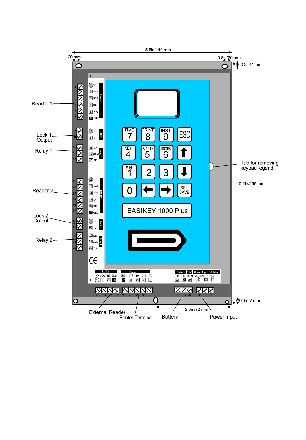
The following diagram shows the Easikey 1000 controller with dimensions, connections, etc.
Figure 1 Easikey 1000 Controller
The Easikey 1000 will need an enclosure and a power supply.
Two boxed versions of the Easikey 1000 are available:
• A “closed” box which must be opened to administer the system.
• An “open” box which has a cutout in the lid which allows access to the keypad without
opening the box. In this instance, only the Installation Engineer should have access to the
box.
Note
EASIKEY 1000 Plus indicates that the controller has door monitoring and alarm relay
facilities, see Section 5.
Installation of the Controller
17047 Ver 1.8 DRAFT C 5 Easikey® 1000
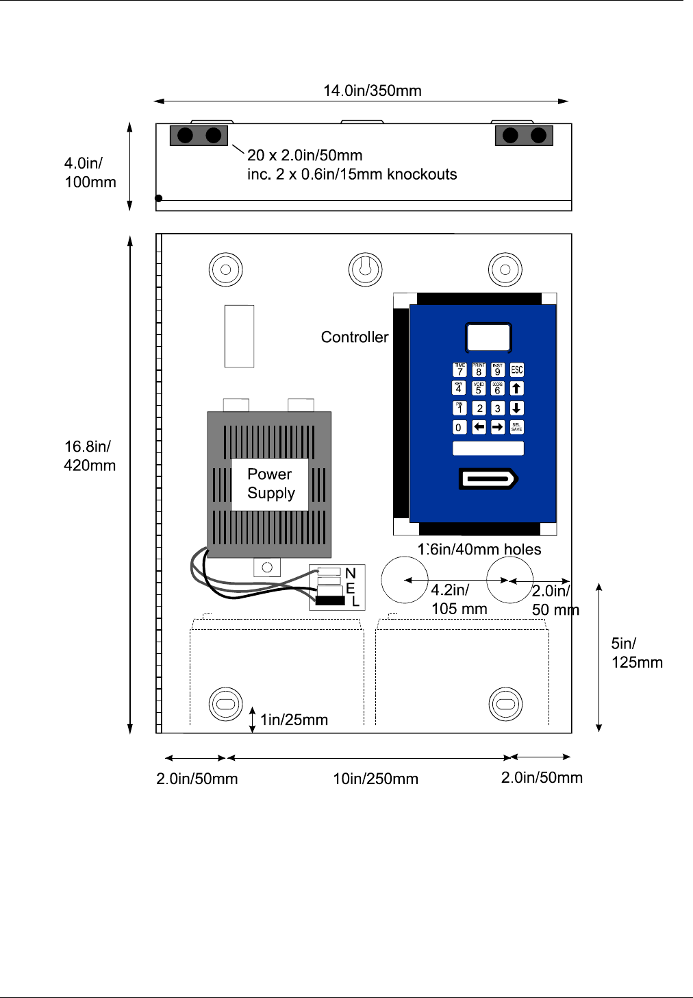
3.2 “Closed” Box Version
This version has a built-in power supply with room in the enclosure for two 6Ah lead acid
batteries.
Figure 2 “Closed” Boxed Easikey 1000
Installation of the Controller
17047 Ver 1.8 DRAFT C 6 Easikey® 1000
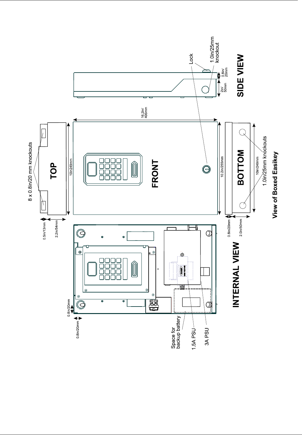
3.3 “Open” Box Version
This version is also available with a built-in power supply with room in this enclosure for one
12V 2.8Ah lead acid battery.
Figure 3 “Open” Boxed Easikey 1000

Installation of the Controller
17047 Ver 1.8 DRAFT C 7 Easikey® 1000
3.4 Power Supply
The Easikey 1000 requires a 12V(3A)/24V(1.5A) dc power supply or an ac transformer rated at
16.5V ac at 1.5A.
Notes
1. The red LED is constantly lit when the alternating current is present except when in the
Editor mode.
2. The controller and two readers require 600mA. In addition, enough current must be
available to power the locks attached to the controller. Therefore, a power supply
capable of providing between 600mA and 3A in total should be used, depending on the
current consumption of the locks.
3. The database is stored in battery-backed memory and will be preserved whether the
controller is powered or not. This backup will last up to 12 months when the controller
is not powered. A NICAD rechargeable, non-replaceable battery is used to provide
memory backup and this is kept at full charge as long as the controller is powered. If
the battery is flat, it will be recharged once power is returned to the controller.
3.4.1 Fuses
The following table details the location, type and rating of each fuse.
Ref Name/Location Type Rating
1.5A
PSU
3A
PSU
FM Mains fuse on mains terminal block HBC, anti-surge 160mA 1A
F1 Battery fuse at bottom of PCB* 20mm glass, quick blow 3.15A 3.15A
F2, F3 Lock supply fuse - by reader
channels*
20mm glass 500mA 1A
* The lock supply and battery fuses are located in vertical fuse holders on the controller.
3.5 Power Supply Connections
The following diagrams show how the different power supplies should be connected to the
controller.
Figure 4 Power Supply Connections

Installation of the Controller
17047 Ver 1.8 DRAFT C 8 Easikey® 1000
3.6 Battery Backup
Battery backup is a feature of the power supply chosen. The capacity of the battery required
should be calculated based on:
• The current consumption of the controller and readers (up to 600mA).
• The current consumption of the locks when operating normally (up to 1A each).
• The type of lock (fail-safe or fail-secure).
• The length of time the system should operate without mains power.
Example
An Easikey 1000 with two readers and two 300mA fail-safe locks will continuously draw
about 1.2A. A 2.8Ah battery will therefore provide approximately 2 hours supply.
Note
The battery is connected to the battery terminals B+ and B-. When the battery is low
(less than 12V), the green LED is constantly lit except when in Editor mode.
3.7 Fitting the Controller
The controller should be mounted in a secure but accessible location bearing in mind that
operators are going to have to program the system at the controller. The controller should be
mounted so that the display is at about eye level.
There are several holes on the backplate that may be used for mounting.
If you are using the Boxed Easikey 1000 there are several holes in the back of the box (see
Figure 2 and Figure 3) that may be used for mounting.
3.8 External Readers
Each Easikey 1000 controller can have an external reader fitted which can be used to
administer the system in conjunction with or instead of the internal reader. The external reader
is used when keys other than proximity are used. The external reader, if used, is connected to
the controller via plug in sockets on connectors 23-26 inclusive situated on the bottom edge of
the controller.
3.9 Printer
3.9.1 Printer Specification
An 80-column dot matrix printer with a serial interface is required. The serial interface must be
set, using switches and/or jumpers, with the following parameters:
• 4800 baud
• 8 data bits, 2 stop bits
• No parity
• Hardware handshake using DTR/CTS. When the printer is busy, it should force DTR low.
PAC have used the EPSON LX series and the OKI Microline 182 printers successfully in the
past.
3.9.2 Printer Cable
The following cable is required:
Use 0.22mm² 4-core unscreened signal cable, maximum length 15m.
Easikey 1000 Printer
5-way printer terminal block 25-pin male D-type connector
TX ———— 3RX
CTS ———— 20 DTR
RX
DTR
GND ———— 7 Signal Ground
Installing Readers and Lock
17047 Ver 1.8 DRAFT C 9 Easikey® 1000
4. Installing Readers and Lock
4.1 Readers
There are several types of readers which can be used with the Easikey 1000, namely:
•Proximity readers.
•PIN readers.
•Magstripe readers (PAC format only).
•Wiegand readers (via PAC Wiegand interface unit).
•AVR readers.
The reader is connected to either reader connector 1 (connections 1-6) or 2 (connections 12-
17). The wiring for each type of reader is described below.
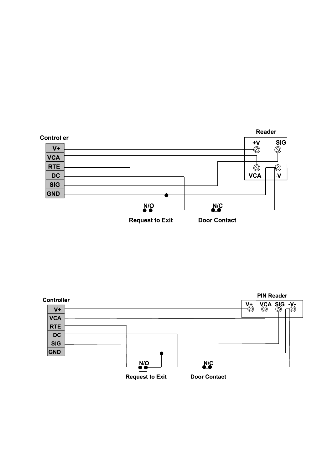
4.1.1 Proximity Reader Wiring
Figure 5 Proximity Reader Wiring Diagram
See Appendix A - Equipment for a list of PAC readers suitable for use with the Easikey 1000.
Use the most appropriate reader for the location bearing in mind, internal or external, vandal
resistance, decor, panel mounting etc.
4.1.2 PIN Reader Wiring
Figure 6 PIN Reader Wiring Diagram
Installing Readers and Lock
17047 Ver 1.8 DRAFT C 10 Easikey® 1000
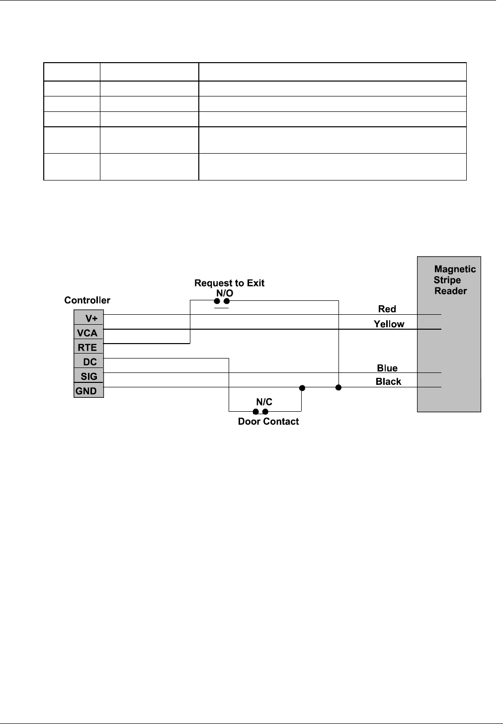
4.1.3 Magstripe Reader Wiring
All connections to the Magstripe reader are made to a 4-conductor flying lead as follows:
Length: 3m Gauge: 7/0.2, 0.22mm²
Colour Signal Notes
Red +12V 12V dc input 9-16V dc, 50mA typical.
Black -V Power and signal return
Blue SIG Signal
Yellow VCA Valid code accept. Active low, LED changes state when
the input falls below 0.6V.
Drain
Wire
This wire should be connected to earth. Do not connect it
to the -V terminal.
Notes
1. Unlike PAC proximity readers, shielded cable is recommended for the interconnection
between the reader and door controller.
2. It is essential that on long cable runs, at least the minimum voltage is maintained at the
reader.
Figure 7 Magnetic Stripe Reader Wiring Diagram
Note
The door contact is optional.
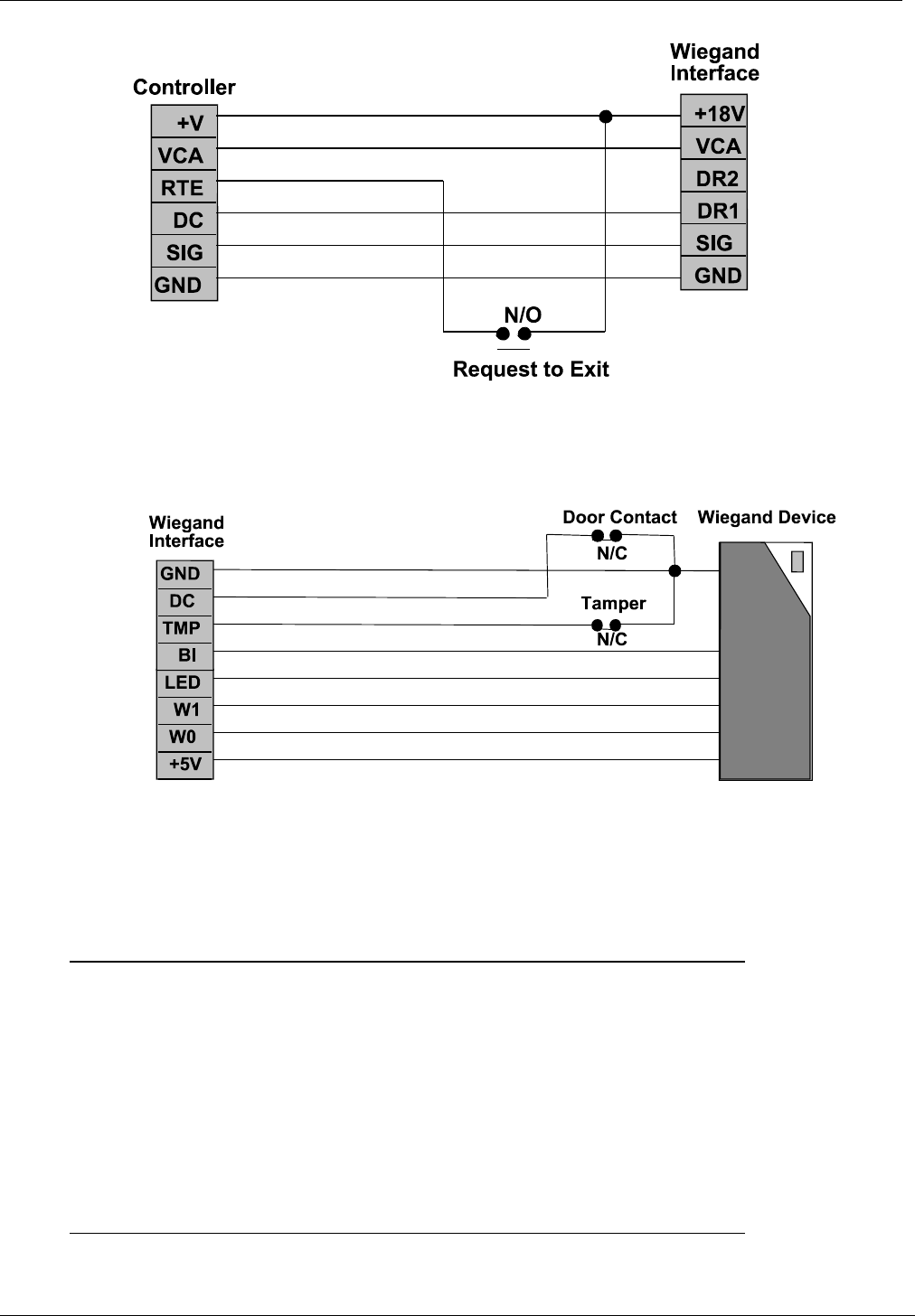
4.1.4 Wiegand Readers Wiring
Wiegand devices are attached using PAC's Wiegand interface unit which converts the Wiegand
code output by the Wiegand device into a format that would be sent by a conventional PAC
reader, making the Wiegand device transparent to the Easikey 1000 controller.
There are two jumper connections on the Wiegand interface unit’s circuit board which should be
set as follows:
Jumper J1 Open
Jumper J2 Closed
Refer to 17132 PAC Wiegand Interface Installation Instructions for full details.
Installing Readers and Lock
17047 Ver 1.8 DRAFT C 11 Easikey® 1000
Figure 8 Easikey 1000 Controller to Wiegand Interface Wiring Diagram
Figure 9 PAC Wiegand Interface to Wiegand Device Wiring Diagram
Note
The door contact is optional.
The following is the wiring for a typical Wiegand device (when no door monitoring or reader
tamper is being used):
Wiegand Interface Wiegand Device
8-way terminal block integral cable or terminals
+5V ────── 5V/+V
W0 ────── DATA0
W1 ────── DATA1
LED ────── LED
BI N/C
TMP ┐
DC ┤
GND ┴───── GND/-V
Figure 10 Typical Wiegand Device Wiring Diagram

Installing Readers and Lock
17047 Ver 1.8 DRAFT C 12 Easikey® 1000
4.1.5 AVR Reader Wiring
Figure 11 AVR Reader Wiring Diagram
Note
A reader with a smaller loop, without the Loop Break and RTE connections, is connected
to the Easikey 1000 to read the transmitter codes into the controller for programming.
4.1.6 Reader Fitting
See the datasheet supplied with the PAC reader being used for specific details for fitting that
type of reader.
In general:
• Readers should be mounted at a convenient height, usually at about the height of a door
handle, on the unhinged side of the door.
• Readers should be mounted at least 1m apart to prevent any interaction between them.
• Consider future service requirements such as access to cables, etc.
4.1.7 Reader Cabling
Use unscreened multistranded tinned copper signal cable, the type commonly used in alarm
installations. The gauge depends on the distance from the controller to the reader and the type
of reader.
4 cores are used to connect the reader itself; the other 2 cores are for the optional request to
exit signal and the optional door monitoring signal.
4.1.7.1 Magstripe Readers
6-conductor, multi-stranded, shielded cable should be used for the following distances and
gauges:
up to 100m 0.22mm²
4.1.7.2 Wiegand Readers
6-conductor, multi-stranded, shielded cable should be used for the following distances and
gauges:
up to 100m 0.22mm²
4.1.7.3 All Other Readers
4/6-conductor, multi-stranded, unshielded cable should be used for the following distances and
gauges:
up to 100m 0.22mm²
The readers are not prone to electrical interference, however avoid routing cable close to heavy
load switching cables and equipment. If this is unavoidable, cross the cable at right angles
every 1-2m.
Installing Readers and Lock
17047 Ver 1.8 DRAFT C 13 Easikey® 1000
4.1.8 Reader Connections
All PAC readers have 4 terminals; +V, VCA, SIG and -V. Each reader is connected to the door
controller reader 1 or reader 2 terminal block. The door controller has 2 further connections,
DC and RTE. These provide door/cable monitoring and request to exit inputs respectively.
Reader
Marking
Description Connects to Controller
6-way terminal block
+V Supply: 12V. V+
VCA Valid code accepted, illuminates the green LED at
the reader.
VCA
Request to exit. RTE
Door monitoring. DC
SIG The signal from the reader to the controller. SIG
-V Supply: 0V. GND
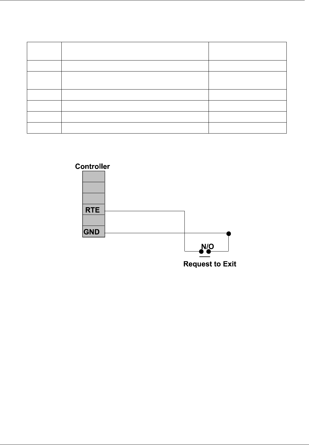
4.2 Request to Exit (RTE)
4.2.1 Wiring Detail
Figure 12 Request to Exit Wiring Diagram
Note
As connecting RTE to ground (-V) will always operate the lock, ensure that the request to
exit wiring is not accessible from outside the secure area (e.g. if the reader is removed
from the wall.)
The Request to Exit switch allows persons within the secure area to leave by signalling to the
door controller to operate the lock without using a key. The switch is necessary when door
monitoring is used (see Section 5) to enable the controller to distinguish between a forced door
and a valid exit.
The switch should be 'normally open' which closes momentarily when pressed.
The switch can be located away from the door, for example, at a reception desk or as part of a
door entry system. In which case, it is possible to change the printed event report to Request
for Entry (see Section 7). More than one switch can be used (if wired in parallel) for a door
if required.
If an attempt is made to keep the door open by holding down the Request to Exit switch, the
door will lock after 5 cycles of the lock release time and, if a printer is fitted, an RTE Button
Held Down report is produced.
Installing Readers and Lock
17047 Ver 1.8 DRAFT C 14 Easikey® 1000
4.3 Door Contact (DC)
The door monitoring facility is described in this section.
4.3.1 Lock Output
Figure 13 Lock Output Wiring Diagram
All locks should be fitted according to the manufacturer’s instructions.
The Easikey 1000 provides a lock output for each reader channel. These outputs are capable
of providing:
• 12V lock at up to 1A each for the dc PSU (part numbers 21450, 21453)
• 12V lock at up to 500mA each for the ac PSU (part numbers 21448, 21452).
Each lock output is protected by a fuse fitted next to the reader connector as follows:
• A 1A, 20mm glass, quick blow fuse for those with the dc PSU.
• A 500mA, 20mm glass, quick blow, fuse for those with the ac PSU.
Each output can be independently set as fail-safe (power to lock) or fail-secure (power to
unlock), see Section 7.
The cable between the door controller and the lock should be of such a gauge as to provide at
least the minimum voltage required to operate the lock. The resistance of the cable and the
current drawn by the lock will determine the type of cable.
4.3.2 Lock Suppression
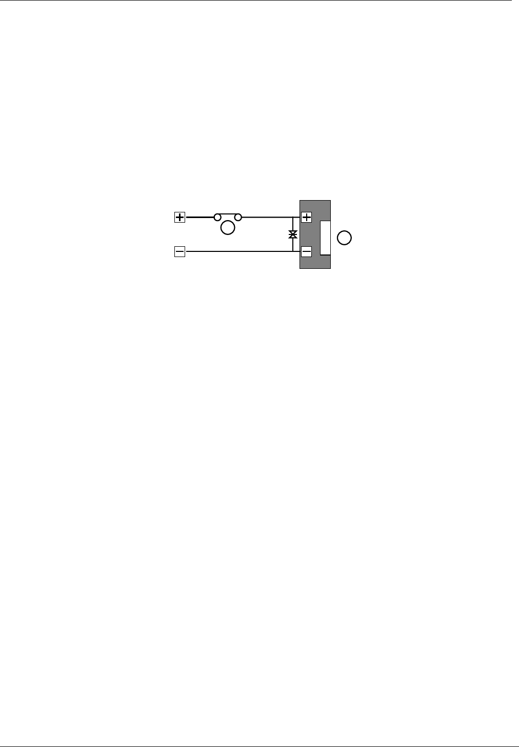
All locks must be fitted with a means of suppressing back EMF ('spikes') generated by most
electric releases, especially magnetic locks. All PAC readers are now supplied with a Metal
Oxide Varistor (MOV). This device should be fitted across the lock terminals at the lock. This
device will prevent long term damage being done to the door controller.
4.3.3 Safety
Any door that is considered a fire door or is on an escape route must have some means of
overriding the electric release in an emergency. Usually this is achieved by the use of fail-safe
locks (power to lock) fitted with a normally closed break-glass in the lock supply. When the
break-glass is operated, the supply to the lock is broken and the door will be released without
any intervention from the door controller.
Door Monitoring and Alarm Relays
17047 Ver 1.8 DRAFT C 15 Easikey® 1000
5. Door Monitoring and Alarm Relays
This section describes the following facilities:
• Door Monitoring. This allows you to monitor each door by using a Door Contact switch.
Unauthorised Access and Door Left Open alarm messages can then be generated
and used to increase the security of the system.
• Alarm Relays. An alarm relay is provided on each door channel which can be used, for
example, to generate an audible alarm when an Unauthorised Access or Door Left
Open situation is detected.
5.1 Wiring Detail
Figure 14 Door Monitoring and/or Tamper Detection Wiring Diagram
5.2 Door Contact Monitoring
The Easikey 1000 has the ability to monitor a door contact allowing the following reports to be
generated:
•Unauthorised Access Alarm which provides warning of a forced door.
•Door Left Open Warning which is generated after a set period of time. This time is
set in the door database (see Section 7).
In addition, there is a cancellation of lock release time which allows the door to lock after
someone has passed through even though the lock release time has not expired.
The door contact should be a Normally Closed switch that is open whenever the door is open.
Care should be taken when fitting door contacts to ensure that they operate only when the door
is opened and close only when it is secure.

Door Monitoring and Alarm Relays
17047 Ver 1.8 DRAFT C 16 Easikey® 1000
To help prevent false alarms:
• Keep reed switches away from large magnetic fields, such as those generated by magnetic
locks. This is a particular problem with metal door frames.
• Ensure that the switch does not operate if the door moves in its frame, in draughty or windy
conditions.
• An efficient door closer should be fitted that secures the door once someone has passed
through.
5.3 Cable/Reader Anti-Tamper
In addition to monitoring a door contact, the DC connection also provides a tamper detection
function. Tamper is detected when the SIG line breaks at the same time as DC opening. This
is achieved whether or not a door contact is fitted. To provide full protection of the cable and
reader the DC core should be terminated at the reader -VE terminal to ensure that the DC to -
VE circuit breaks when the reader is removed.
IMPORTANT
Tamper detection does not operate when the door is manually unlocked, automatically
unlocked via a time profile or while the door is open through the use of a key or RTE.
The functions described here are set up in the door database. See Section 7 for details on how
these facilities are enabled.
5.4 Alarm Output Relay
COM
NO
NC
Common
Normally Open
Normally Closed
Relay
A relay is provided on each channel with Common, Normally Open and Normally Closed
terminals. Both relays have the same fixed function, changing over in the event of an
Unauthorised Access alarm or a Cable/Reader Anti-Tamper alarm. The relay will
change back when the alarm is accepted.
Alarm relay 1 is activated for alarms on reader 1 and alarm relay 2 is activated for alarms on
reader 2. Each relay is de-activated when it is accepted by an editor key or the door is closed.
Note
The relay changes over for the Door Left Open warning.
The relay contacts are rated at 0.4A at 125V ac and 2A at 30V dc.
Note
When channel interlock is active, alarms on both readers activate alarm relay 1. Alarm
relay 2 is not used.
Door Monitoring and Alarm Relays
17047 Ver 1.8 DRAFT C 17 Easikey® 1000
5.5 Emergency Override/Free Exit
There is a special case where both the RTE and DC signals are interpreted differently to those
described above. The RTE signal is used to monitor an Emergency switch, such as a break
glass, and DC provides a Free Exit report. See Section 7.1.4 for how to enable this feature.
Note
When this feature is used, there is no tamper detection and no door alarm monitoring.
Figure 15 Emergency Override/Free Exit Wiring Diagram
5.5.1 Emergency Override
When connected as shown, operating the break glass will open the door and produce an
Emergency Override On report at the printer. When the switch is restored an Emergency
Override Off report is produced and the door will be locked again.
Note
This feature should not be fitted as the sole means of escape, see Section 4.3.3.
5.5.2 Free Exit
In the case of the door contact, this will produce a Free Exit report and operate the lock
when the switch is opened. A Normally Closed switch may be used to operate as a Request
to Exit switch in addition to having a door contact switch in series. The door contact will allow
Door Left Open warnings to be produced.
Note
The lock will operate whenever the door contact is opened. Care should be taken that
the door contact cannot be broken from the secure side of the door.

Setting Up the System
17047 Ver 1.8 DRAFT C 18 Easikey® 1000
6. Setting Up the System
Follow this section through to set up the system for the first time.
6.1 Switching On
Once the door controller is fitted, with readers and locks in place, the unit can be powered up
for the first time. The procedure for initial start-up is as follows:
1. Disconnect all reader, lock and printer terminal blocks at the controller.
2. Apply the 12V dc power. The screen will briefly display 8888 and beep 4 times. The
display will then be clear and the red power-on LED will light.
3. Connect the first reader.
4. If fitted, operate the RTE for the first reader. If no RTE is fitted, use a short piece of wire to
short RTE to -V at the terminal block. The display should show oP and the green LED on
the reader should illuminate.
5. Repeat for the second reader if required.
6. Now install the master key (see Section 6.2).
7. Program the door data (see Section 7).
8. Connect the locks and ensure they operate in accordance with the door data settings.
9. Check the clock (see Section 14.1).
6.2 Installing the Master Key
To install the master key:
1. Press the small Reset button, SW1, situated on the top left-hand corner of the circuit board.
The controller will beep 4 times. While it is beeping press the Reset button again. The
display will flash all its horizontal bars.
2. Present an ID device (proximity token, Magstripe card, etc) to the controller reader being
used (either internal or external). This will become the master key.
3. The controller will beep and the display will alternate between CLr and ALL? This
means "Do you want to wipe out the whole database?". If this is a new, unprogrammed
system, the answer should be "Yes". Press VOID/5 followed by SEL/SAVE to wipe out the
database. If you do not want to wipe out the whole database, just press ESC.
IMPORTANT
If you are replacing, the master key, press ESC. The display will clear. Present the new
master key. The display will show:
indicating that you are in Editor mode and may select one of the functions.
When the master key is installed, after wiping the database the following parameters are set:
•The master key is also installed as user key 0001 with access through both doors and no
time profile set.
•Each door is given a lock release time of 5 seconds.
•Each lock is set to fail secure (power to unlock).

Setting Up the System
17047 Ver 1.8 DRAFT C 19 Easikey® 1000
6.3 Replacing the Master Key
To replace the master key follow the steps shown above in Section 6.2 but when the display
alternates between CLr and ALL? , press ESC to preserve the existing database.
When the database is preserved, nothing is changed except that the master key is installed in
the key database with complete access. It will normally go into position 0001 replacing the old
master key unless another key has this number, in which case it goes in the next available
position.

Setting the Door Data
17047 Ver 1.8 DRAFT C 20 Easikey® 1000
7. Setting the Door Data
The DOORS/6 key allows you to set up or change various parameters concerning the doors
and locks. These parameters are described below, followed by a procedure for setting them.
7.1 Description of Parameters
7.1.1 Lock Release Time
This is the amount of time that the lock will be operated. Usually about 5 seconds is sufficient to
allow people to open the door. You may need to set a longer time for older or disabled people.
When door monitoring (see Section 5) is used, any unexpired lock release time is cancelled as
soon the door closes.
7.1.2 Door Open Time
This is the amount of time allowed after the expiry of the lock release time before a door left
open warning is given. Usually between 10 and 20 seconds is set.
A value must be entered here if door monitoring and/or cable tamper detection is required. If
this value is 0, door and cable monitoring is disabled. It may be useful at times to disable
door monitoring while investigating the cause of false alarms.
7.1.3 Door Time Profile
Here a time profile, 1-8, is entered if automatic opening and closing is required. See Section 12
for more details.
7.1.4 Door Options
There are 5 options that can be set. Each is displayed as a vertical bar, full height when set,
half height when not set.
7.1.4.1 Lock Mode
UNSET Lock operates as fail-secure, power applied to unlock door.
SET Lock operates as fail-safe, continuous power to keep door secure, removed to
unlock.
7.1.4.2 Free Exit
This option modifies the way that DC and RTE are monitored.
UNSET DC monitors door contact and reader/cable tamper.
RTE is request to exit.
SET DC will give Free Exit without an alarm.
RTE gives Emergency Override On when closed, Emergency Override
Off when opened.
7.1.4.3 RTE Report
This option controls the type of report printed when RTE is operated.
UNSET Request to Exit
SET Request for Entry
7.1.4.4 AVR
This option must be set if an AVR reader is to be used.
UNSET Any attached AVR will not be recognised.
SET Any attached AVR attached will be recognised.

Setting the Door Data
17047 Ver 1.8 DRAFT C 21 Easikey® 1000
7.1.4.5 Set/Reset
UNSET Presenting a key to the reader will release the lock for the time specified by the lock
release time.
SET Presenting a key to the reader will release (unlock) the lock. It will stay in this state
until the key is again presented to the reader when the door will again lock.
7.2 The DOORS/6 Function
Press ÏÐ at any time to move between door 1 and door 2.
Press ÍÎ at any time to move between parameters. The parameters are presented in the
order described above.
Press ESC at any time to return to SEL?
Step Example Display Action
1 Present an editor key to the controller reader.
2SEL? Press DOORS/6.
3d1Lt / 005 Lock release time for door 1.
Either: Type a new time, 0-255, followed by SEL/SAVE,
or Press Ð to go to door 2,
or Press Î to go to next parameter.
4d1dt / 000 Door open time for door 1.
Either: Type a new time, 0-255, followed by SEL/SAVE,
or Press Ð to go to door 2,
or Press ÍÎ to go to next parameter.
5d1tP / 0 Time profile for door 1.
Either: Type a new time profile 0-8 followed by
SEL/SAVE,
or Press Ð to go to door 2,
or Press ÍÎ to go to next parameter.
6d1oP /IIIII Door options for door 1. See Section 7.1.4 for descriptions of
each option.
Either: Press 1,2,3,4 or 5 to set or unset followed by
SEL/SAVE.
or Press Ð to go to door 2,
or Press ÍÎ to go to next parameter.
7d1UL / LoC Manual lock/unlock for door 1.
See Section 14.4.

Installer Facilities
17047 Ver 1.8 DRAFT C 22 Easikey® 1000
8. Installer Facilities
This section describes facilities available using the INST/9 key.
8.1 Setting the Clock
It is important when using time profiles, or if you are using the printer to log events, that the
clock and calendar are checked regularly. Use the following procedure for setting the clock:
•If at any point you enter an invalid value, like 15 for the month, you will get a long beep
and the original value re-displayed.
•If the date is invalid, e.g. 31/06/93, you will be returned to the year value, step 4 in the
procedure below. Re-enter the correct month and date.
Step Example Display Action
1 Present an editor key to the controller reader.
2SEL? Press INST/9
3SEtC Press SEL/SAVE
4Yr93 Type the new year value (e.g. 93) and press SEL/SAVE. Press
Ð to move to the next item.
5Mt05 Type the new month value (e.g. 05) and press SEL/SAVE.
Press Ð to move to the next item.
6dt06 Type the new day value (e.g. 06) and press SEL/SAVE. Press
Ð to move to the next item.
7dy2 Type the day of the week, Mon=1, Tue=2, Wed=3, Thu=4,
Fri=5, Sat=6, Sun=7, and press SEL/SAVE. Press Ð to move
to the next item.
8Hr11 Type the hour and press SEL/SAVE. Press Ð to move to the
next item.
9Mn08 Type the minute and press SEL/SAVE.
The clock is now set. Press ESC.
10 SEL? Press ESC to leave the Editor mode.
8.2 Upload/Download
It is possible to use the serial ports on two Easikey 1000 controllers to copy the database from
one to the other.
To do this a cable should be made up as follows:
Use 0.22mm² 4-core unscreened signal cable, maximum length 15m.
Easikey 1000 Easikey 1000
5-way printer terminal
block (connector no.)
5-way printer block
terminal (connector no.)
GND (27) ———— GND (27)
DTR (28) ———— CTS (30)
RX (29) ———— TX (31)
CTS (30) ———— DTR (28)
TX (31) ———— RX (29)
Once the two controllers are connected the following procedure should be performed:
Note
The transfer can be cancelled at any time by pressing ESC at both controllers.

Installer Facilities
17047 Ver 1.8 DRAFT C 23 Easikey® 1000
Step Sending Unit Receiving Unit Action
1 Present an editor key to each controller
reader.
2SEL? SEL? Press INST/9 at each controller.
3SetC SetC Press Ð at each controller.
4in in Press Ð again at sending controller only.
5oUt in To start the transfer:
Press SEL/SAVE twice on the receiving
controller then:
Press SEL/SAVE twice on the sending
controller.
6oUt / nnn in / in The sending controller will display oUt
alternating with the percentage complete.
The receiving controller will flash in.
When complete, both displays will return
to SEL?
7SEL? SEL? Press ESC to leave Editor mode.
8.3 Editor Keys
This function is fully described in Section 13.
8.4 Channel Interlock
When a reader is used on both sides of a door to monitor both entry and exit, it is only
necessary to feed one lock. The same lock, lock 1, will be operated by both reader 1 (entry)
and reader 2 (exit). Lock 2 is not used. Door monitoring and RTE, if used, are on channel 1.
Step Example Display Action
1 Present an editor key to the controller reader.
2SEL? Press INST/9.
3SetC Press Ð 4 times.
4P00 Press Î to toggle Channel Interlock ON/OFF
5P00.
6SEL? Press ESC to leave Editor mode.

Installer Facilities
17047 Ver 1.8 DRAFT C 24 Easikey® 1000
8.5 Anti-Passback
When two readers are used to control both entry into an area and exit out of the area, anti-
passback may be set. This will prevent a key being used to enter an area it has already been
used to enter first leaving the area. If an attempt is made to use the key to enter the area again,
a No Access: Pass Back report will be generated on the printer. As with channel interlock,
channel 1 is considered the entry reader and channel 2 the exit reader.
Passback may either be active until the key is used to leave the area, or a time limit may be
assigned after which the key may be used to enter the area again. The time limit is useful if
people are likely to leave the area without using their keys, without the time limit they would be
unable to get back in the area.
Step Example Display Action
1 Present an editor key to the controller reader.
2SEL? Press INST/9.
3SetC Press Ð 4 times.
4P00 or
P00. if Channel
Interlock is set.
Type a value followed by SEL/SAVE.
0 No pass back
1 Pass back with no time limit.
2-60 Number of minutes after which a key will work again if
it is not used to leave the area.
5P15 (with an anti-
passback time set
to 15 mins)
6SEL? Press ESC to leave Editor mode.
8.6 Software Version Display
It may be useful at times to verify the software version used in the controller. You may be
asked for this by PAC Technical Support.
Step Example Display Action
1 Present an editor key to the controller reader.
2SEL? Press INST/9.
3SetC Press Ð 5 times.
4v100 In this case version 1.00 is displayed. Press ESC.
5SEL? Press ESC to leave Editor mode.
System Administration
17047 Ver 1.8 DRAFT C 25 Easikey® 1000
9. System Administration
9.1 The Controller Keypad and Display
This section describes how to use the controller keypad to administer the system.
Figure 16 Controller Keypad and Display
9.2 Editor Keys
In order to perform any administration on the system, an editor key is required. This allows the
operator to access editing functions at the controller and also to accept alarms.
There is one master key which is a special editor key that can add or remove editor keys as well
as perform other editor key functions.
The master key is created when the system is first installed, although it can be changed at a
later date if lost or stolen.

System Administration
17047 Ver 1.8 DRAFT C 26 Easikey® 1000
9.3 How to use an Editor Key
Whenever any changes need to be made to the system an editor key should be presented to
the built-in key reader. If the key is valid the screen will display SEL? From this point, press
one of the following keys:
PIN/1 Allows the PIN number associated with a key to be displayed
KEY/4 Allows keys to be added or edited.
VOID/5 Allows keys to be removed from the system.
DOORS/6 Allows the door information, including manual lock/unlock, to be edited.
TIME/7 Allows time profiles to be set up and alter.
PRINT/8 Allows the use of print functions.
INST/9 Provides access to clock setting, add/delete editor keys, set channel
interlock, set anti-pass back and upload/download
ESC Leaves Editor mode.
Other keys used when in Editor mode are:
ÍÎÏÐ Arrow keys for moving around.
SEL/SAVE Used when entering data or to confirm operations.
9.3.1 Entering Data
You will need to enter different types of data at certain points in Editor mode. Important points
to remember:
• Whenever you add or change any data item you must press SEL/SAVE to confirm.
• You can press ESC to leave the data unaltered.
Different types of data use different methods:
• Typing: For instance when you need to enter a key number or a time in a time profile.
When pressed, each number appears at the cursor position, a flashing underline. You can
use the arrow keys, ÍÎ, to move the cursor position.
• Toggling: In this case, pressing certain keys changes the state of the data. For example,
when changing days of the week in time profiles, pressing 1 for Monday, 2 for Tuesday, etc.,
will change the current state; if it is on, pressing the key will switch it off and vice versa.
9.3.2 Editor Time-Out
If after entering Editor mode, no keys are pressed or no key is presented to the controller
reader for 3 minutes, the Editor mode will time-out. This means it will return to the normal
display and the editor key will have to be presented again. This can be a useful feature if you
are not sure how to get out of the system - just leave it and it will automatically leave Editor
mode.
Displays and Alarms
17047 Ver 1.8 DRAFT C 27 Easikey® 1000
10. Displays and Alarms
The Easikey 1000 door controller will display various characters on its 4-character screen and
produce a sound as a response to certain conditions. These are described below.
Also included in this section are example printer reports produced when a printer is attached to
an Easikey 1000.
10.1 Power Indicators
When not in Editor mode (to add/delete keys, etc.) the red and green LEDs are used as power
indicators as follows:
• The red LED is constantly lit indicating that ac supply is healthy.
• The green LED is constantly lit when the battery (if any) is low (less than 12V).
These are not referred to elsewhere in the document and it is assumed that power is supplied to
the unit.
10.2 Normal Displays
When nothing is happening, the display is blank and no sounds are produced.
Whenever a door is opened normally, either with a key or by using a Request to Exit switch,
the display will show:
Door 1 Open Door 2 Open Both Doors Open
Printer Example
DATE TIME DOOR USER TRANSACTION
[0123] 12/06/95 10:34 1 0092 Access Authorised
[0124] 12/06/95 10:35 2 Request to Exit
[0125] 12/06/95 10:50 2 Manual Unlock
[0126[ 12/06/95 13:30 1 Automatic Unlock
10.3 Door Left Open Warning
This warning will only be given if door monitoring is being used - check with the installer of the
system to see if this is the case.
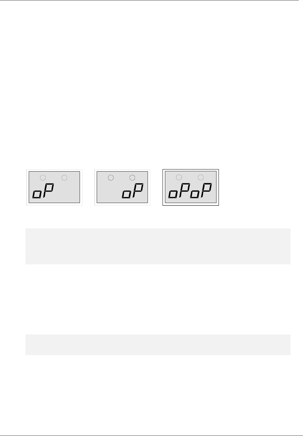
If a door is left open longer than the time set, the oP(shown above) will start to flash for the
particular door left open. The oP will continue to flash until the door is closed. There is no
sound associated with this warning.
Printer Example
DATE TIME DOOR USER TRANSACTION
[0233] 12/06/92 12:34 1 Door Left Open
[0234] 12/06/92 12:35 1 Door Closed
Displays and Alarms
17047 Ver 1.8 DRAFT C 28 Easikey® 1000
10.4 Unauthorised Access Alarm
This alarm will only be given if door monitoring is being used - check with the installer of the
system to see if this is the case.
If a door is opened without a key being used, time profile being active, manual unlock used or a
Request to Exit switch being pressed, the controller interprets this condition as
Unauthorised Access. In this case, the alarm has to be accepted by presenting an editor
key to the controller reader.
This alarm gives exactly the same displays and sounds as for Cable or Reader Tamper
alarm (see Section 10.6). However, the printer report is different.
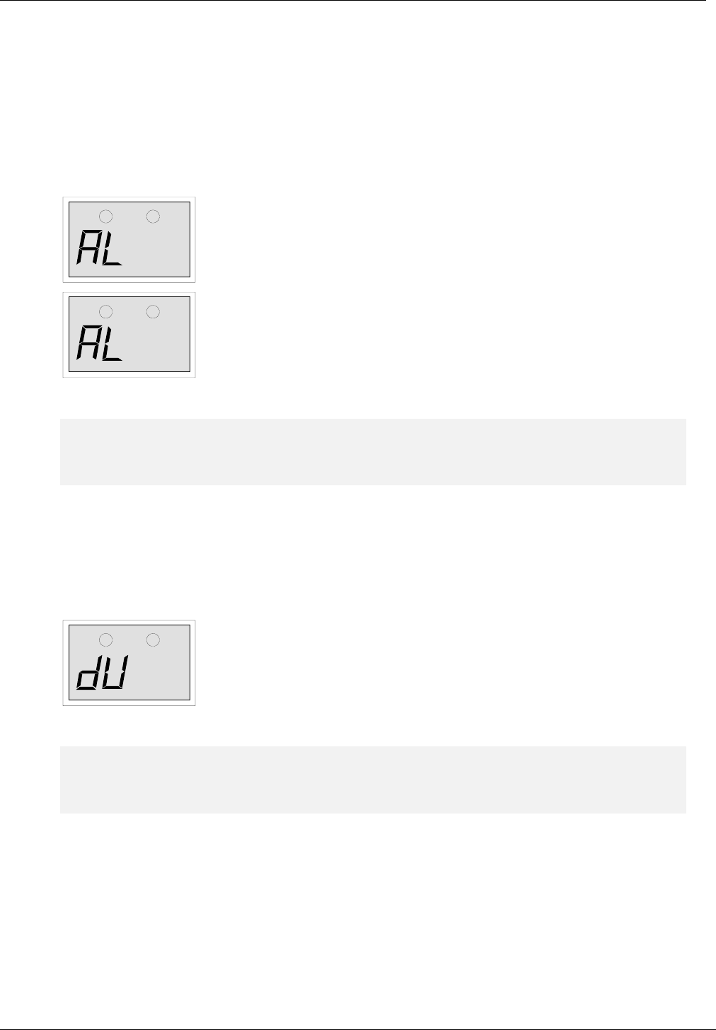
Display AL, Flashing
Sound Every 2 seconds
Unauthorised access or cable tamper.
Present editor key to accept, the sound will stop.
Display AL, Steady
Sound Silent
Accepted alarm or cable/reader tamper.
The alarm condition still exists, either the door is still open or the
cable/reader is still tampered.
Printer Example
DATE TIME DOOR USER TRANSACTION
[0278] 12/06/92 13:34 1 Unauthorised Access
[0282] 12/06/92 13:35 1 MASTER Local Alarm Accepted
[0285] 12/06/92 13:37 1 Alarm Cleared
10.5 Duress Alarm
This alarm will only be given if a PIN reader is being used and the keyholder is forced to open
the door under duress. If the PIN is, for example, 1234, the keyholder may enter 1235 instead.
This will open the door but send a code to the controller indicating that the door has been
opened under duress.
The alarm generated at the controller is as follows:
Display dU, Flashing
Sound Every 2 seconds
PIN Code Duress.
Present editor key to accept the alarm; the sound will stop and
display will clear.
Printer Example
DATE TIME DOOR USER TRANSACTION
[0278] 12/06/92 13:34 1 PIN Code Duress
[0282] 12/06/92 13:35 1 MASTER Local Alarm Accepted

Displays and Alarms
17047 Ver 1.8 DRAFT C 29 Easikey® 1000
10.6 Cable or Reader Tamper Alarm
This alarm will only be given if the reader has been wired to detect this condition - check with
the installer of the system to see if this is the case.
This alarm gives exactly the same displays and sounds as for Unauthorised Access alarm
(see Section 10.4). However, the printer report is different.
Printer Example
DATE TIME DOOR USER TRANSACTION
[0278] 12/06/92 13:34 1 Anti-tamper Alarm
[0282] 12/06/92 13:35 1 EDITOR - 1 Local Alarm Accepted
[0285] 12/06/92 13:37 1 Alarm Cleared
10.7 Alarm Relays
In the case of the Easikey 1000 alarms (Door Left Open, Unauthorised Access and
Cable or Reader Tamper), the alarm relays can be used to operate, for example, an
audible alarm such as a siren, etc.
Adding and Voiding Keys
17047 Ver 1.8 DRAFT C 30 Easikey® 1000
11. Adding and Voiding Keys
11.1 Key Numbers
A key, when added into the system, is given a number between 0001 and 1000. Normally when
a key is added it will be given the first available number in the list. For example, if a system
contained keys 0001, 0002, 0003, 0004 and 0006, the next key added would be given number
0005, the following keys would be 0007, 0008 and so on. However, it is possible to override the
automatic number and give a key a specific number, provided the number is not already in use -
see Section 11.2.3.
It is important to keep a record of key numbers issued (on the Programming Worksheet) as it
may be necessary to void a lost key at a later date, in which case the number given to the key
must be known.
11.2 Access Levels and Time Profiles
Each key added to the system can be assigned an access level and a time profile. This defines
which doors the key is allowed through and at what times and days the key can be used.
If you decide to use access levels and/or time profiles, it is a good idea to group all keys with
the same access requirements together as this makes adding blocks of keys much easier.
11.2.1 Access Levels
A key may be allowed access to door 1 only, door 2 only, both doors or neither door. Allowing a
key access to neither door can be useful when a key is lost or stolen. Rather than using VOID it
may be better to lock the key out then, if a printer is fitted, there will be a record if an attempt is
made to use the key.
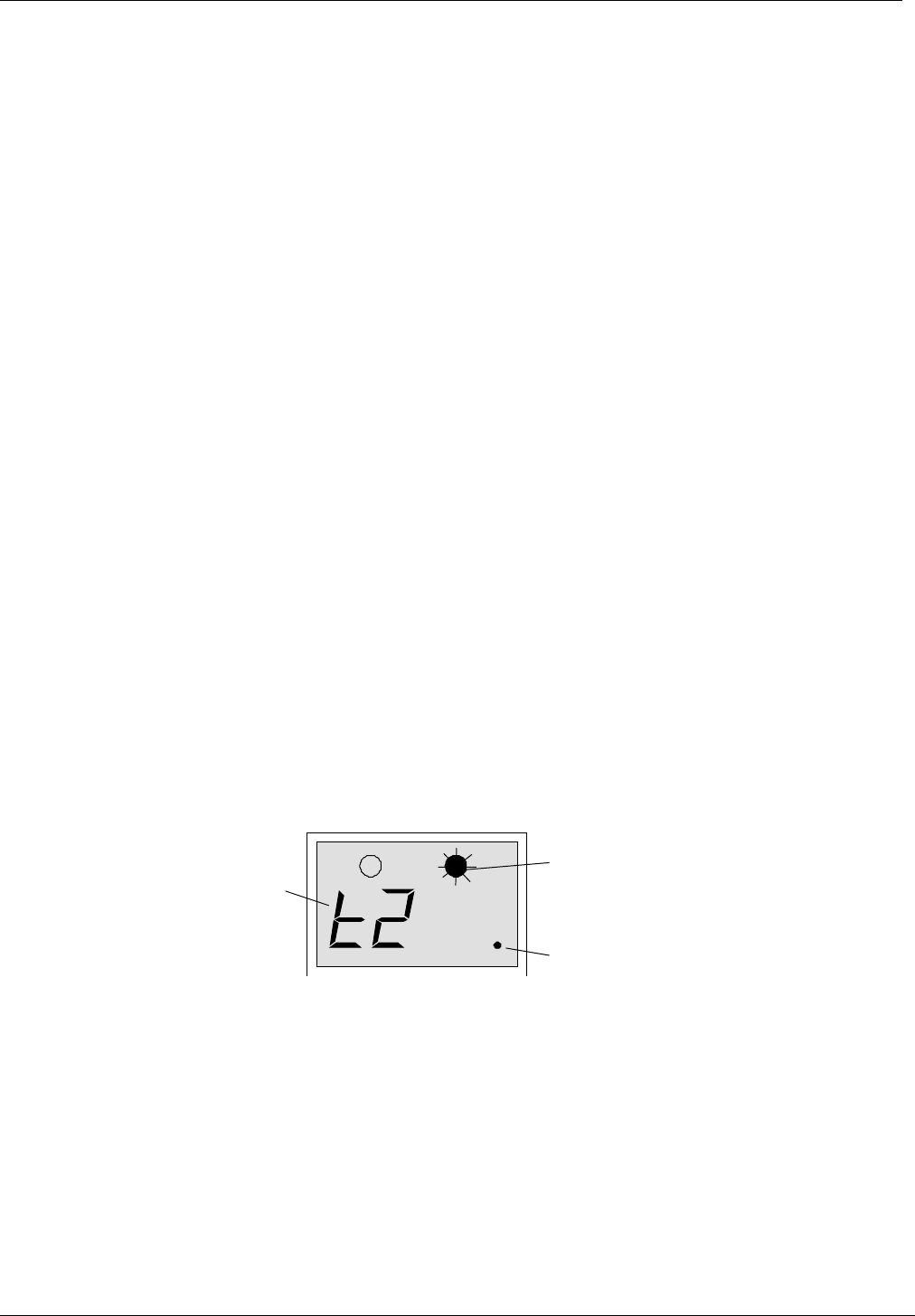
When adding or editing a key, the access level is displayed as two dots on the right of the
display, the left half of the display indicating time profile. If the first dot is lit, that key will have
access to door 1, the second dot indicates access to door 2 (see Figure 17). If neither dot is lit,
the key is locked out.
11.2.2 Time Profiles
A key may be restricted to which days and at what times it may be used. This is done by
assigning one of 8 different time profiles to the key. If a key is assigned a time profile of 0, there
will be no time restriction at all; it will operate 24 hours a day, 7 days a week.
See Section 12 for more details on how to create and use time profiles.
Time Profile set to 2
Green LED flashing, Adding a key
Access to door 2 only
Figure 17 How the System Displays Access Level and Time Profile When Adding a Key

Adding and Voiding Keys
17047 Ver 1.8 DRAFT C 31 Easikey® 1000
11.2.3 Adding a New Key
Follow the procedure shown below for adding a new key. If you are adding more than one new
key, see Section 11.3.
Step Example Display Action
1 Present an editor key to the controller reader.
2SEL? Press the KEY/4 key.
30000 Present a new key to the controller reader.
4
0019 / t0..
At this point, if both the green and red LEDs come on, the key
already exists in the database and may be edited (see Section
11.4). If this is a new key, the green LED only will flash and
the display will alternate between the next available key
number and the time profile and access level. The example
shows key 0019 as the next available number.
At this point you may wish to select your own number rather
than the number given by the system. If not, go to step 6
below.
To select an alternative number press SEL/SAVE, the display
will change to:
50000 Now either type in the number you require and press
SEL/SAVE, or use the Ï and Ð keys to go up and down the
list of numbers. Numbers already assigned will flash with the
red and green LEDs steady, free numbers will alternate with
their time profile and access level and the green LED flashing.
60019 / t0.. Now any changes can be made to the access level and time
profile. If no changes are to be made, go to step 8.
7
0019/t1.
To change the time profile, press 1-8 for the time profile you
wish to apply. As soon as you press a key the display will stop
alternating. Press SEL/SAVE to confirm. The display will start
flashing again.
To change access levels, press Í to toggle on/off the dot for
door 1, and Î to toggle on/off the dot for door 2.
The example shows key 0019 with time profile 1 and access
through door 2 only.
8
0020/t1.
Present the editor key (it must be the same one as used in
step 1 above) to the controller reader. The green LED will now
go steady and the next available number will flash.
If you wish to add more keys see Section 11.3; otherwise,
press ESC.
9SEL? Press ESC to leave Editor mode.

Adding and Voiding Keys
17047 Ver 1.8 DRAFT C 32 Easikey® 1000
11.3 Adding Several Keys
When you want to add several keys in one go, this can be easily done by following the Section
11.2.3 procedure until the end of step 8. At this point, instead of pressing ESC take the
following steps:
Step Example Display Action
9
0020/t1.
The green LED will be steady and the next available key number
will be alternating with its access level and time profile.
Make any changes to the access level and time profile as
described above.
Notice that any changes are carried over to the next key making it
very convenient for adding keys with the same access
requirements.
Present the new key to the controller reader - there is no need to
present an editor key.
10 0021/t1.
0022/t1.
0023/t1.
Continue presenting new keys, one after the other, until all keys
are recorded.
If a key is presented that is already in the database, its number
will briefly be displayed before the display returns to the next
available number.
If you fill the database with 1000 keys, the display will show
FULL.
11 0024/t1. When finished, either press ESC or present the editor key.
12 SEL? Press ESC to leave Editor mode.
11.4 Editing a Key
To change the access level or time profile assigned to a key, you require either the key itself or
the number assigned to the key. The key is edited using the following procedure.
Step Example Display Action
1Present an editor key to the controller reader.
2SEL? Press the KEY/4 key.
30000 Either: present the key to the controller reader,
or: type the key number and press SEL/SAVE,
or: use ÏÐ to select the key number and press
SEL/SAVE.
If the green LED is flashing, the key presented is not in the system
or the number selected is unused.
40019 / t1.. If the key presented or the number selected is in the database,
both red and green LEDs will be on, and the display will be
alternating between the key number and the access level/time
profile. In the example, key 0019 has been selected, has time
profile 1 assigned and is allowed through both doors.
Make any changes as described in Step 7 of Section 11.2.3.
5t2 . The display will go steady, press SEL/SAVE to confirm.
60019/t2. You will be returned to the alternating display. Return to step 3 if
you want to change other keys (press SEL/SAVE if you want to
type another number).
Otherwise, press ESC .
7SEL? Press ESC to leave Editor mode.

Adding and Voiding Keys
17047 Ver 1.8 DRAFT C 33 Easikey® 1000
11.5 Voiding a Key
A key can be removed from the database provided you have the key or you know its number.
Note
If a key has been lost or stolen and you have a printer fitted, it may be better to edit the
key’s access level to provide no access (see Section 11.2.1) rather than void it. This will
then show if an attempt is made to use the missing key.
To void a key use the following procedure:
Step Example Display Action
1 Present an editor key to the controller reader.
2SEL? Press the VOID/5 key.
30000 The red LED will be lit.
Either: present the key to the controller reader. If you
present a key that does not exist, there will be a
long beep.
or: type the key number and press SEL/SAVE,
or: use ÏÐ to select the key number and press
SEL/SAVE.
Valid keys will flash along with the red LED; invalid keys will
flash with red and green LEDs steady.
40019 Present the editor key to delete the key.
There will be a confirming beep and the display will return to:
5SEL? Return to step 2 above to delete more keys or press ESC to
leave Editor mode.
Note
See Section 13.2 on how to void editor keys
11.6 Identifying a Key
If a key is found it can quite easily be identified by presenting it to the controller reader:
Step Example Display Action
1 Present an editor key to the controller reader.
2SEL? Press the KEY/4 key.
30000 Present the key to the controller reader.
40019/t1. If the key exists in the controllers database, the red and green
LEDs will be steady and the key number, alternating with its
access level/time profile, will be displayed.
Press ESC twice to leave Editor mode or follow Section 11.4
procedure if you wish to make any changes.

Time Profiles
17047 Ver 1.8 DRAFT C 34 Easikey® 1000
12. Time Profiles
Time profiles are a powerful tool for restricting access of personnel or for automating the
opening and closing of doors.
Typical examples are:
1. A public access door through which anybody can pass between 9:00am and 5:00pm,
Monday to Friday, but outside these hours a key is required.
2. Some staff are only allowed access between 8:30am and 5:30pm, Monday to Friday;
8:30am to 12:00pm Saturday.
3. Cleaners are allowed access only between 7:00am and 9:00am Monday to Saturday.
4. Shift workers can gain access between 8:00pm and 6:00am Monday to Friday.
Note
If you give a door a time profile of 0, it will require a key 24 hours a day, 7 days a week. If
you give a key a time profile of 0, it will have access 24 hours a day, 7 days a week. If
you are never going to use time controls of any type, there is no need to set up any time
profiles at all, just use a time profile of 0 for both doors and keys.
12.1 How They Work
There are 8 different time profiles. Each time profile consists of up to three time periods. A time
period consists of a begin time, an end time and the days of the week to which it applies. For
instance, example 1 above requires just one time period, 9:00am (begin time) to 5:00pm (end
time) Monday to Friday (days of the week); example 2 requires two time periods, 8:30am to
5:30pm Monday to Friday plus 8:30am to 12:00pm Saturday only.
Time profiles applied to doors will automatically open the door at the begin time of each time
period and automatically close the door at the end time of each time period. Doors can also be
manually locked and unlocked, see Section 14.4.
Time profiles attached to a key will allow access only when the time at which the key is
presented falls within the time profile.
It is recommended that different time profiles are used for doors and personnel even if they are
identical. This means that if a change is required to the door opening times at a later date,
these can be achieved without affecting the personnel access times and vice versa.
When using time profiles, it is important to check the time and date at regular intervals, say
once a month, to ensure that the system operates accurately, see Section 8.1.
Notes
1. A time profile always starts at the beginning of the first minute of the time period. That
is, in example 1, when the time changes from 8:59 am to 9:00 am. A time profile
always finishes at the end of the final minute of the time period. That is when the time
changes from 5:00pm to 5:01pm.
2. A time period cannot cross midnight. When, as in example 4 above, it is necessary to
cover such a time, two time periods are required, one from the begin time up to
midnight (use 23:59), with another time period from midnight (use 00:00) to the end
time.
In addition to the 3 time periods, each time profile has a status setting, either ON or OFF. When
a time profile is in use, its status will be ON; when it is OFF, the effect depends on the
application:
• When applied to personnel, a time profile that is switched OFF will lock out all personnel with
that profile until the time profile status is switched back ON.
• When applied to a door, a time profile that is switched OFF will stop the door automatically
opening. It will also lock a door that is currently open according to that time profile.
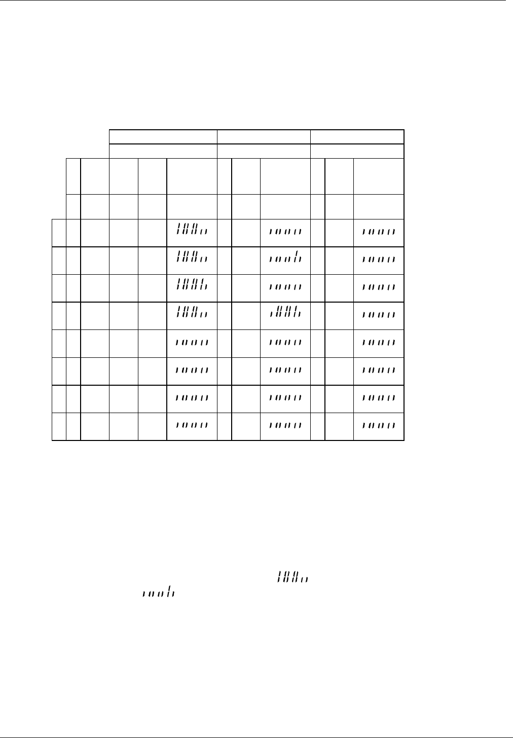
Time Profiles
17047 Ver 1.8 DRAFT C 35 Easikey® 1000
12.2 How to Set Time Profiles
Setting up time profiles is achieved by presenting an editor key and pressing the TIME/7 key.
The first display you will see is the status of time profile 1 shown as T1St alternating with on
or oFF.
It is best to think of the time profile database as a grid, 8 rows representing time profiles, 10
columns being one for the Status and three for each time period. You use the ÍÎÏÐ keys to
move a 'window' around the grid. If you attempt to move outside the window there will be a
beep.
ÍÎ
Time Period A Time Period B Time Period C
Stat. begin End days be
gi
n
End days be
gi
n
End days
ntnSt tnAb tnAE tnAd tn
bb
tnbE tnbd tn
Cb
tnCe tnCd
1on 0900 1700 00
00
0000 00
00
0000
2on 0830 1730 08
30
1200 00
00
0000
Ï3on 0700 0900 00
00
0000 00
00
0000
4on 2000 2359 00
00
0800 00
00
0000
5oFF 0000 0000 00
00
0000 00
00
0000
Ð6oFF 0000 0000 00
00
0000 00
00
0000
7oFF 0000 0000 00
00
0000 00
00
0000
8oFF 0000 0000 00
00
0000 00
00
0000
Wherever you are in the grid, you will see the item name alternating with the item value. When
you press a number key to make a change, the display will go steady. Work through the
example given below as this shows you in detail how to change values. Changes are made as
follows:
• You change the status by pressing the 1 key, i.e. pressing 1 will reverse whatever is
currently displayed. Press SEL/SAVE when the correct status is displayed.
• You change times by typing the 4 digits in 24 hour format, e.g. for 1.00pm you would
press 1,3,0 and 0 followed by SEL/SAVE to confirm.
• The day periods are set by switching on or off seven vertical bars in the display. For
instance, Monday to Friday is represented as , while Saturday only would be
represented as . Each bar is changed by pressing 1-7, where 1 represents
Monday, 2 Tuesday up to 7 for Sunday.

Time Profiles
17047 Ver 1.8 DRAFT C 36 Easikey® 1000
Example
Add time profile 5 with two time periods, 8:00am to 1:00pm Monday to Friday and 2:00pm
to 6:00pm Monday to Thursday (I.e. no access allowed at lunch times or Friday
afternoon):
Step Example Display Action
1 Present an editor key to the controller reader.
2SEL? Press TIME/7
3t1St / on The status of time profile 1 (may be either on or oFF).
Press Ð 4 times to get to time profile 5.
4t5St / oFF Press 1, the display will go to a steady on. Notice if you
press 1 again the display will change back to oFF.
Make sure on is displayed and press SEL/SAVE to
confirm.
5t5St / on Press Î.
6t5Ab / 0000 The begin time of period A (00:00). Type 0800 followed
by SEL/SAVE. Notice how the display goes steady as
soon as you press a key.
7t5Ab / 0800 Press Î.
8t5AE / 0000 The end time of period A (00:00). Type 1300 (for 1:00pm)
followed by SEL/SAVE.
9t5AE / 1300 Press Î.
10 t5Ad / The days for period A (none at the moment). Type 12345
followed by SEL/SAVE. Notice that as each number is
pressed the corresponding bar doubles in size. Press the
same number again and it goes back to half size.
Make sure the first 5 bars (Mon, Tue, Wed, Thu, Fri) are
set.
11 t5Ad / Press Î.
12 t5bb / 0000 The begin time of period B (00:00). Type 1400 followed
by SEL/SAVE.
13 t5bb / 1400 Press Î.
14 t5bE / 0000 The end time period B. Type 1800 followed by
SEL/SAVE.
15 t5bd / The days for period B. Type 1234 followed by
SEL/SAVE.
16 t5dd / You have completed both time periods for this time profile.
Now make sure that the third time period is clear. Press
Î.
17 t5Cb / 0000 Should show 0000, if not, press 0000 followed by
SEL/SAVE. Press Î.
18 t5CE / 0000 Should show 0000, if not, type 0000 followed by
SEL/SAVE. Press Î.
19 t5Cd / Should show , if not press appropriate numbers to
make all bars half size. Press ESC twice to leave Editor
mode.

Time Profiles
17047 Ver 1.8 DRAFT C 37 Easikey® 1000
This completes the setting up of a complete time profile.

Editor Keys
17047 Ver 1.8 DRAFT C 38 Easikey® 1000
13. Editor Keys
This section describes how to administer editor keys. These functions can only be performed
when using the master key.
The system allows up to 5 editor keys to be assigned, each one being able to accept alarms,
and use Editor mode. Making a key, an editor key will not automatically allow it to be used at a
door. If this is required, it should be added as a user key as well.
13.1 Adding an Editor Key
Step Example Display Action
1 Present the master key to the controller reader.
2SEL? Press the INST/9 key.
3SetC Press Ð 3 times.
4Edit Press SEL/SAVE.
5E000 Present the new key to the controller reader.
6E002 At this point, if the red LED comes on and the number flashes,
the key already exists as an editor. If this is a new key, the
green LED only will flash and the display will flash. The
example shows key 2 as the next available number.
7E003 Present the master key to the controller reader. The green
LED will now go steady and the next available number will
flash.
You may add more editor keys now if you wish.
8SEL? Press ESC to leave Editor mode.
13.2 Voiding an Editor Key
Note
The master key cannot be voided.
Step Example Display Action
1 Present the master key to the controller reader.
2SEL? Press the INST/9 key.
3SetC Press Ð 3 times.
4Edit Press SEL/SAVE.
5E000 Either present the key to the controller reader,
or type the key number and press SEL/SAVE,
or use ÏÐ to select the key number and press SEL/SAVE.
Existing keys will flash along with the red LED. Invalid keys will
flash with red and green LEDs steady.
6E003 Present the master key to delete the key.
There will be a short beep and the display will return to:
7SEL? Return to step 2 above to delete more keys or press ESC to
leave Editor mode.
Other Functions
17047 Ver 1.8 DRAFT C 39 Easikey® 1000
14. Other Functions
14.1 Setting the Clock
This is described in Section 8.1.
14.2 Display PIN
Where a PIN reader is being used with the Easikey 1000, it is necessary to know the PIN before
the key is issued as the key must be presented to the reader and the PIN entered to open the
door. To find the PIN associated with a key:
Step Example Display Action
1 Present an editor key to the controller reader.
2SEL? Press PIN/1.
3Show/Id Present the key to the reader.
41234 PIN number displayed.
Note
The PIN is derived from the key/card and cannot be changed.
14.3 Display Last Five Keys Used
Note
No editor key is required for this function.
It is possible to display the last five keys used on the readers connected to the Easikey 1000
controller as follows:
• Press the KEY/4 key. This displays the last key to be used with the left (red) LED lit if
access was through door 1. The right (green) LED is lit if access was through door 2.
• Press KEY/4 to display the next key used. Up to five keys can be displayed. On the sixth
press the display goes blank.
Note
The display will blank after ten seconds if no key is pressed.
Last key used
was key 23 Access through
door 2
Figure 18 Sample Display
14.4 Manual Lock and Unlock
It is possible to manually lock and unlock a door from the controller. It may be necessary to do
this, for instance when a door needs to be kept open while contractors are working in an area,
or equipment is being moved around. Also a door normally open on a time profile may need to
be locked while a receptionist or guard is not available.
14.4.1 Doors Controlled by a Time Profile
Manual lock will lock the door, keys will then be required to gain access. If no further action is
taken, the door will unlock again at its next automatic opening time.
If the door is manually unlocked and no further action is taken, it will lock again at its next
automatic closing time.
14.4.2 Doors not Controlled by a Time Profile
Manual unlock will unlock the door and it will stay unlocked until manually locked again.

Other Functions
17047 Ver 1.8 DRAFT C 40 Easikey® 1000
14.4.3 To Lock/Unlock a Door
Use the following procedure to lock/unlock a door:
Step Example Display Action
1Present an editor key to the controller reader.
2SEL? Press DOORS/6.
3d1Lt / 0005 Press Î 4 times.
4d1UL / Loc The display now shows the current state of door 1
(Loc=locked, ULoC=unlocked).
To lock/unlock, door 2 press Ð.
5d1UL / Loc
or
d2UL / Loc
To unlock a door, press 1 followed by SEL/SAVE, the display
will change to ULoC and the door will unlock.
To lock a door, press 0 followed by SEL/SAVE, the display will
change to LoC and the door will lock.
Press ESC.
6SEL? Press ESC to leave the Editor mode.
14.5 Printer Functions
14.5.1 Transaction Logging
All Easikey 1000 door controllers keep a record of the most recent 1000 transactions, a
transaction being any of the different types of event that may occur such as Access
Authorised, Manual Lock, Automatic Lock, Editor On, etc. (see Appendix C -Transactions
for details of all the different types of transaction).
When a printer is connected, the controller will print these events as they happen. If the printer
is switched off, or otherwise disconnected, the events will be stored and printed from the point
at which printing stopped when the printer is reconnected.
The only action the user need take is to ensure that the printer is kept supplied with paper, does
not jam, and make sure the paper flows freely through the printer.
Sample Transaction Printout
DATE TIME DOOR USER TRANSACTION 15/06/93
[0054] 15/06/93 12:09 2 Door Left Open
[0055] 15/06/93 12:10 2 Door Closed
[0056] 15/06/93 12:14 1 0045 Access Authorised
[0057] 15/06/93 12:14 2 0052 No Access: Level
[0058] 15/06/93 12:15 EDITOR - 1 Editor On
[0059] 15/06/93 12:17 EDITOR - 1 Editor Off
[0060] 15/06/93 12:18 1 Request to Exit
[0061] 15/06/93 12:19 1 0045 Access Authorised
[0062] 15/06/93 12:23 1 0045 Access Authorised
[0063] 15/06/93 12:30 1 Automatic Unlock
[0064] 15/06/93 12:33 2 0120 No Access: Time
[0065] 15/06/93 12:42 2 Unauthorised Access
[0066] 15/06/93 12:43 2 MASTER Local Alarm Accepted
[0067] 15/06/93 12:44 2 Alarm Cleared
Other Functions
17047 Ver 1.8 DRAFT C 41 Easikey® 1000
14.5.2 User Selected Reports
There are 3 features accessible to the user from the PRINT/8 key.
•Printout of the database including personnel, keycode, time profiles and door data.
•Printout of transactions applying to an individual key.
•Clearing all transactions in the controller.
14.5.3 Printing the Database:
This function prints personnel, time profile and door data. The printer will automatically go to
the top of a new page, the display will show the progress of the report.
Press ESC to interrupt the printout.
1 Present an editor key to the controller reader.
2SEL? Press PRINT/8
3PrdA Press SEL/SAVE to start database printout.
4db / Prnt
tP / Prnt
dr / Prnt
..printing personnel database
..printing time profiles
..printing door data
5SEL? Press ESC to leave Editor mode.
Sample Database Printout
Easikey 1000 SYSTEM PERSONNEL PRINTOUT 05/06/93 11:10 page 01
ID KEYCODE DOORS TIME 1 TIME 2 TIME 3
0001 12345678 1,2
0002 BD5B54E6 1 08:30 17:30 MTWTF-- 08:30 12:00 -----S- 00:00 00:00 -------
0003 6B0604BC 2 08:30 17:30 MTWTF-- 08:30 12:00 -----S- 00:00 00:00 -------
0045 174DE464 1,2
0052 0A032469 1
0064 D803E43D 1,2 20:00 23:59 MTWTF-- 00:00 08:00 -TWTFS- 00:00 00:00 -------
Easikey 1000 SYSTEM TIME PROFILE PRINTOUT
RECORD STATUS TIME 1 TIME 2 TIME 3
1 On 09:00 17:00 MTWTF-- 00:00 00:00 ------- 00:00 00:00 -------
2 On 08:30 17:30 MTWTF-- 08:30 12:00 -----S- 00:00 00:00 -------
3 On 07:00 09:00 MTWTFS- 00:00 00:00 ------- 00:00 00:00 -------
4 On 20:00 23:59 MTWTF-- 00:00 08:00 -TWTFS- 00:00 00:00 -------
5 Off 00:00 00:00 ------- 00:00 00:00 ------- 00:00 00:00 -------
6 Off 00:00 00:00 ------- 00:00 00:00 ------- 00:00 00:00 -------
7 Off 00:00 00:00 ------- 00:00 00:00 ------- 00:00 00:00 -------
8 Off 12:30 13:30 MTWTF-- 00:00 00:00 ------- 00:00 00:00 -------
Easikey 1000 SYSTEM DOOR DATA PRINTOUT
Door 1 LOCK TIME = 005
DOOR TIME = 010
TIME PROFILE = 8
OPTIONS = Reverse Lock, Request to Exit
DOOR = Locked

Other Functions
17047 Ver 1.8 DRAFT C 42 Easikey® 1000
Door 2 LOCK TIME = 005
DOOR TIME = 010
TIME PROFILE = 0
OPTIONS = Request to Exit
DOOR = Locked
14.5.4 Printing Selected Key Transactions
This will print all the transactions associated with a particular key number currently in memory.
The period of time this covers will depend on how long the system takes to generate 1000
transactions.
Press ESC to interrupt the printout.
1 Present an editor key to the controller reader.
2SEL? Press PRINT/8.
3PrdA Press Ð.
4Prtr Press SEL/SAVE.
50000 Type the key number you require, press SEL/SAVE.
There may be a short pause while the controller searches
through all the transactions.
6tr /Prnt Printing transactions
7SEL? Press ESC to leave Editor mode.
Sample Transaction Printout for User 45
Easikey 1000 SYSTEM PERSONNEL PRINTOUT 05/06/93 11:10 page 01
DATE TIME DOOR USER TRANSACTION
[0056] 05/06/93 12:14 1 0045 Access Authorised
[0061] 05/06/93 12:19 1 0045 Access Authorised
[0062] 05/06/93 12:23 1 0045 Access Authorised
[0092] 05/06/93 12:30 2 0045 No Access: Level
14.5.5 Clearing the Transaction Memory
This is useful if no printer has been connected for some time and you do not want up to 1000
old transactions to be printed.
1 Present an editor key to the controller reader.
2SEL? Press PRINT/8.
3PrdA Press Ð.
4Prtr Press Ð.
5CLrt Press SEL/SAVE.
6CLr /ALL? Press VOID/5 followed by SEL/SAVE to erase all transactions
from memory.
There will be a short confirming beep.
7SEL? Press ESC to leave the Editor mode.

Appendix A - Equipment
17047 Ver 1.8 DRAFT C 43 Easikey® 1000
15. Appendix A - Equipment
This appendix contains a complete list of all PAC equipment suitable for use with the Easikey
1000. Any PAC item not contained in this appendix should be considered unsuitable for this
product. If in doubt, check with PAC Technical Support.
PAC Part No. Description
Door Controllers
21446 Easikey 1000 - 2 door controller.
21450 Boxed Easikey 1000 with 1.5A PSU (in metal case)
21448 Boxed Easikey 1000 with 3.0A PSU (in metal case)
21453 Boxed Easikey 1000 with 1.5A ac PSU (in metal case with cutout)
21452 Boxed Easikey 1000 with 3.0A ac PSU (in metal case with cutout)
Easi Readers
20377 Mullion - black
20387 Mullion - white
20421 Panel mount reader
20378 Vandal resistant - stainless steel
20388 Vandal resistant - brass
PAC Readers
40031 Magstripe reader
20360 Flush mount PAC PIN - stainless steel (brass also available)
20461 Surface mount PAC PIN - stainless steel (brass also available)
20530 AVR reader module
ID Devices
21020 Token - electronic proximity key.
20263,
20264
20270
20266
20267
Proximity card - plain
Proximity card -PAC logo
Proximity card - plain (recommended for printing and lamination
purposes)
Proximity card - plain with mag stripe (not encoded)
Proximity card - PAC logo with mag stripe (not encoded)
40025
40026
Magstripe hi-co card - uncoded
Magstripe hi-co card - coded
20087 AVR transmitter
Ancillary Products
20742 Wiegand interface unit

Appendix B - Using External Readers
17047 Ver 1.8 DRAFT C 44 Easikey® 1000
16. Appendix B - Using External Readers
16.1 Introduction
Two different types of ID device can be used on each Easikey 1000, one of which must be a
proximity key (card). System administration is via the built-in reader for proximity keys/cards
and via an external reader attached to the controller for other types of ID devices.
There are four types of external reader which can be used with the Easikey 1000, namely:
•PAC Magstripe Readers.
•PAC PIN Readers.
•PAC AVR Readers.
•Wiegand Readers (via PAC Wiegand interface unit).
Note
Only one of the above can be used with proximity keys on any system. You cannot have
a system which supports both Magstripe readers and PIN readers.
Whichever external reader is required (if any) is connected to the external reader connectors
(23-25 inclusive) on the bottom of the controller.
Note
Where a Wiegand reader is used, this is connected using a PAC Wiegand Interface Kit.
16.2 Magstripe Readers
Where a Magstripe reader is connected to the Easikey 1000, card administration is exactly the
same as for key administration. For example, to install a card as the master key, the procedure
is as described in Section 6.2 section except that instead of presenting the card to the built-in
reader it is swiped through the Magstripe reader.
16.3 PIN Readers
Where a PIN reader is connected to the Easikey 1000, card administration is exactly the same
as for fob administration. For example, to install a card as the master the procedure is as
described in Section 6.2. When a PIN reader is used the card must be presented to the reader
and the associated PIN entered.
Note
PIN time profiles are not available
To find out what the PIN is for a card:
Step Example Display Action
1 Present an editor key to the controller reader.
2SEL? Press PIN/1.
3Show/Id Present the key to the reader.
41234 PIN number displayed.
5SEL? Press ESC to leave the Editor mode.
Note
The PIN must be provided to the User along with card.
A duress feature is also available if a PIN reader is used. For example, if the PIN is 1234, a PIN
of 1235 can be entered (PIN plus 1). This will open the door but generates an alarm indicating
that the door was opened under duress.

Appendix B - Using External Readers
17047 Ver 1.8 DRAFT C 45 Easikey® 1000
16.4 AVR Readers
Where an AVR reader is connected to the Easikey 1000, administration is exactly the same as
for key administration. For example, to add an AVR to the system the procedure is as
described in Section 11.2.3. A “mini-loop” is set up to administer the system.
Note
Before administering AVRs the AVR option must be set as detailed in Section 7.1.4.
16.5 Wiegand Readers
Where a Wiegand reader is connected to the Easikey 1000 via a PAC Wiegand interface unit,
card administration is exactly the same as for key administration. For example, to install a card
as the master the procedure is as described in Section 6.2.
16.6 Keys
Throughout this document reference has been made to "presenting keys". Where other ID
devices are used this should be taken to mean:
•Magstripe Swipe card through the reader.
•Wiegand Swipe card through the reader
• AVR Pass transmitter over the loop.

Appendix C -Transactions
17047 Ver 1.8 DRAFT C 46 Easikey® 1000
17. Appendix C -Transactions
Normal Entry and Exit
Access Authorised Normal key authorisation.
Entry Authorised Only used when anti-pass back or interlock is set. Key
has entered area.
Exit Authorised Only used when anti-pass back or interlock is set. Key
has left the area.
Request to Exit Normal use of Request to Exit switch.
Request for Entry Special use of Request to Exit switch, see Section 7.
Free Exit Special use of Request to Exit switch, see Section 7.
Alarms and Warnings
Unauthorised Access A locked door has opened without a valid key being
used or a Request to Exit switch being pressed.
Anti-tamper Alarm The cable has been cut or the reader removed or
disconnected.
Local Alarm Accepted An editor key has accepted the alarm.
Alarm Cleared The previous alarm condition has been cleared, i.e. the
door has been secured or the cable/reader has been
reconnected.
Door Left Open The door has been left open longer than the pre-set
time.
Door Closed The door has closed again after being left open.
RTE Button Held down The Request to Exit switch is being held down.
Repeated Token Use The same key has been presented more than 5 times in
succession.
PIN Reader Duress The PIN plus one (eg 1235 instead of 1234) has been
entered to indicate door opened under duress
No Access
No Access: Unknown ID A key has been presented that is not recognised by the
controller.
No Access: Locked Out A key with no access at either door has been presented.
No Access: Level A key allowed access at the other door has only been
presented at this door.
No Access: Time A key currently excluded from this door with a time
profile has been used.
No Access: Pass Back A key has been excluded because it has been used
twice on the same reader in succession.
Door Events
Automatic Lock The door has locked automatically via a time profile.
Automatic Unlock The door has unlocked automatically via a time profile.
Manual Lock An editor has manually locked the door.
Manual Unlock An editor has manually unlocked the door.

Appendix C -Transactions
17047 Ver 1.8 DRAFT C 47 Easikey® 1000
Other Events
Editor On An editor key has entered Editor mode.
Editor Off An editor key has left the Editor mode or the Editor
mode has timed-out.
Emergency Override On Special use of Request to Exit switch. The switch is
monitoring an Emergency switch (e.g. a break glass).
Emergency Override Off Special use of Request to Exit switch. The switch is
monitoring an Emergency switch (e.g. a break glass).
Unit Closed Down Power removed from the door controller.
Unit Started Up The door controller has been switched on.

Appendix C -Transactions
17047 Ver 1.8 DRAFT C 48 Easikey® 1000
This page is intentionall left blank.

Appendix C -Transactions
17047 Ver 1.8 DRAFT C 49 Easikey® 1000
This page is intentionally left blank.

Appendix C -Transactions
17047 Ver 1.8 DRAFT C 50 Easikey® 1000
Declaration of Conformity
Application of Council Directives 73/23/EEC
Standard(s) to which conformity is declared EN55022-B, EN55082-1
Manufacturer's Name PAC INTERNATIONAL LTD
Manufacturer's Address 1 Park Gate Close, Bredbury, Stockport, U.K. SK6 2SZ
Type of Equipment Access Control Systems
Product Equipment Easikey 1000 Series
I, the undersigned, hereby declare that the equipment specified above conforms to the above directive(s) and
standard(s).
Signed Date 30th August 2001
Full Name Richie Herkes Position Managing Director