PAC EK-PNL Low range proximity reader User Manual 17063
PAC International Limited Low range proximity reader 17063
PAC >
Revised manual
DATASHEET
PAC INTERNATIONAL LTD, 1 Park Gate Close, Bredbury, Stockport, SK6 2SZ, England
Tel: +44 (0) 161 406 3400. Fax: +44 (0) 161 430 8658
www.pac.co.uk
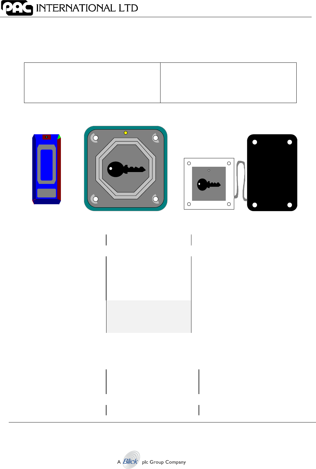
Easikey Readers
Mullion, Vandal Resistant and Panel Mount
17063 Ver 1.6 DRAFT B January 2003
20377 Mullion Reader-Black
20387 Mullion Reader-White
20378 Vandal Resistant Reader-Steel
20388 Vandal Resistant Reader-Brass
20421 Panel Mount Reader
CAUTION
These readers are suitable for connection to
Easikey and Easikey 1000 only. They should
not be connected to any other type of
equipment (e.g. PAC 2100/2200 series).
1. Introduction
Mullion Vandal Resistant * Panel Mount *
Items Enclosed
Mullion reader Vandal resistant reader Panel mount reader and head
4 terminal screws 4 terminal screws 4 terminal screws
MOV MOV MOV
Mounting backplate 4 x 1¼" No. 8 VR screws Lexan window and backplate
Label
2 x 1" No.6 self-tapping
screws
A special screwdriver
(available separately) is
required for the Vandal
Resistant (VR) screws.
Note
The readers come with a 6-wire suppression lead that should be installed as described in
this datasheet. This cable must be installed to comply with CE regulations.
Dimensions
H x W x D mm
83 x 3.38 x 12
H x W x D mm
100 x 100 x 12
H x W x D mm
92 x 62 x 15 Reader
60 x 60 x 12 Head
Maximum Reading Range
25mm 8mm 8mm

Introduction
17063 Ver 1.6 DRAFT B 2 Easikey Readers
Specification for all readers
Operating Temperature: -40C to +50C
Current: 90mA (maximum)
Supply Voltage: 9-16v DC (supplied by the controller)
Cable Type: 4 or 6-conductor, multi-stranded, unscreened
Cable Distances: Up to 100m from controller using 7/0.2 (0.22mm²)
RFID Devices
As similar RFID technology is now widely used in a number of other industries, for example
automotive immobilisers, it is possible that interaction between your access control ID and other
devices may cause one or the other to function incorrectly. Should you suspect that you have
experienced such a problem the solution is to separate your access control ID from other RFID
devices.
FCC Notice
This device complies with part 15 of the FCC rules. Operation is subject to the following two
conditions (1) this device may not cause harmful interference, and (2) this device must accept
any interference received, including interference that may cause undesired operation.
Mullion Reader FCC ID OQL-EK-MUL
Vandal Resistant Reader FCC ID OQL-EK-VN
Panel Mount Reader FCC ID OQL-EK-PNL
Changes or modifications not expressly approved by the party responsible for compliance could
void the user's authority to operate the equipment.
Installation
17063 Ver 1.6 DRAFT B 3 Easikey Readers
2. Installation
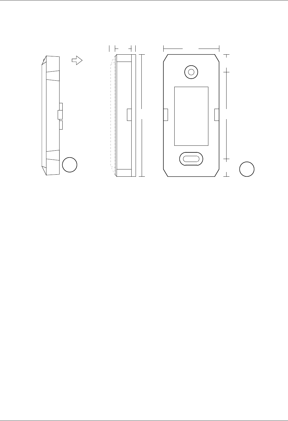
2.1 Mullion Reader - Installation
84
10 3
60
38
12
12
4
AB
This reader comes in two parts, the reader itself (A) with 4 terminals and the backplate (B). The
backplate has a 3mm rubber spacer at the rear.
2.1.1 Fixing the Reader
1. The cable from the controller should be routed through the aperture in the backplate. Leave
enough cable exposed to allow easy wiring of the reader (at least 20mm).
Note
There is limited room between the reader and backplate. You should ensure there is a
void large enough behind the backplate to accommodate any excess on the suppression
cable.
2. Fix the backplate to a flat surface using the No.6 screws provided - or a fixing suitable for
the material to which the reader is being mounted. The two holes are 60mm apart. Use the
top (round) hole first, and the lower (oval) hole to ensure the reader is straight.
3. Ensure that the reader cable is not connected to the controller. Wire the reader to the cable
as described in the documentation supplied with the controller.
4. Push the reader, with the green LED to the top, onto the backplate, the fixing tabs on each
side should snap into place.
5. 5. Place label on front of reader.
2.2 Removing the Reader
The reader can be removed from the backplate by placing a small flat-bladed screwdriver into
the apertures on each side of the backplate. Take care not to damage the reader or backplate.
Vandal Resistant Reader - Installation
17063 Ver 1.6 DRAFT B 4 Easikey Readers
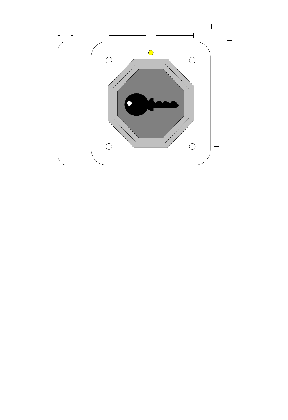
3. Vandal Resistant Reader - Installation
12
100
100
70
705
5
This reader should be mounted using the Vandal Resistant screws provided.
Note
A special screwdriver (not supplied) is required to use these screws.
3.1 Fixing the Reader
The cable from the controller should come to the rear of the reader. Leave enough cable
exposed to allow easy wiring of the reader (at least 20mm).
Note
The terminals protrude 5mm from the rear of the reader. You should ensure there is a
void large enough (about 40mm square and 20mm deep) behind the reader to
accommodate the terminals and excess suppression cable.
1. Ensure that the reader cable is not connected to the controller. Wire the reader to the cable
as described in the documentation supplied witrh the controller.
2. Apply a silicone sealant to the terminals to protect against moisture if the reader is mounted
outside.
3. Fix the reader to as flat and even a surface as possible. This will reduce the possibility of it
being levered from the wall. Either use the Vandal Resistant screws provided, or other
suitable fixings. The LED should be to the top.
Panel Mount Reader - Installation
17063 Ver 1.6 DRAFT B 5 Easikey Readers
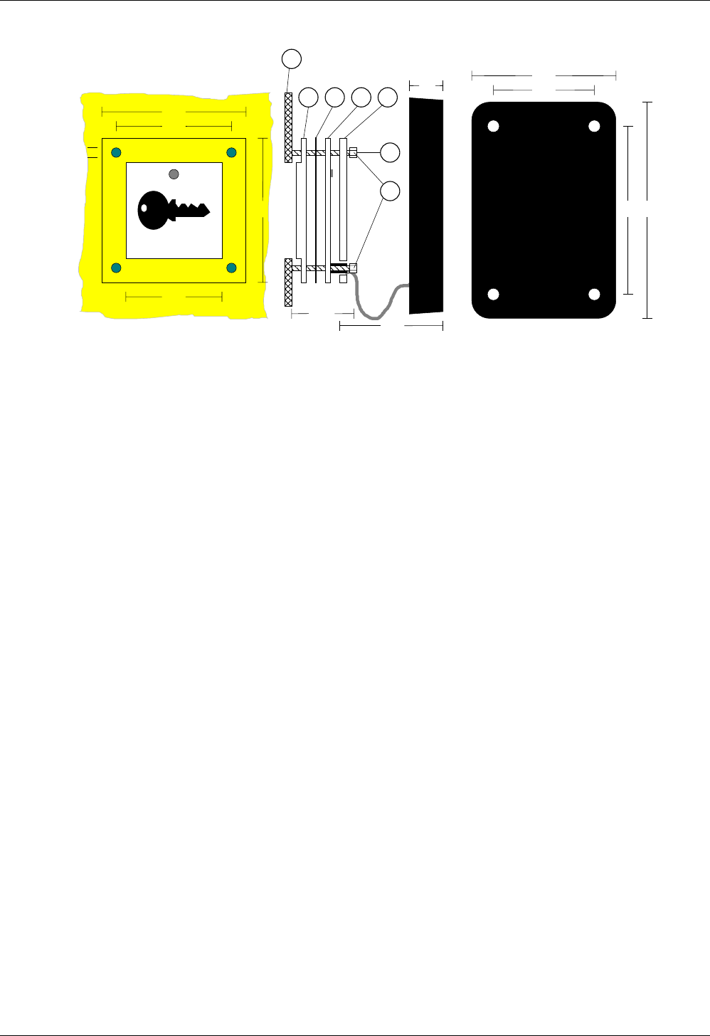
4. Panel Mount Reader - Installation
9070
60
42
14
60
48
40
60
4
60
A B C D
E
F
G
15
This reader is designed to be mounted in a steel panel (E), such as used in a door-entry
system. There are two main units; the main module, a black rectangular unit, connected by a
fixed length of cable to a reading head. The cable between the two parts is fixed, 60mm long
and should not be cut, extended or shortened.
4.1 Panel Aperture
The reading head is designed to fit a 40mm square hole. Holes on the reading head, 48mm
between centres, accept M3 fixing studs (F). The studs should be at least 15mm long. The front
cover (A) protrudes 2.5mm through the aperture.
4.2 Locating the Main Module
Mount the module in a convenient place behind the panel. The holes in each corner will accept
No. 6 screws. Ensure that the module is close enough to the reader head to allow the panel to
be removed without straining the cable. Wire the Module to the cable as described in the
documentation supplied with the controller.
4.3 Fixing the Reading Head
There are 4 components to the reading head:
1. Remove the protective film from the front lexan window (A). Mount on the studs so that the
centre fits through the aperture, with the shallow slot to the bottom.
2. Remove the backing from the label, and fit to the circuit board (C), the clear hole should
align with the green LED.
3. Place the circuit board (C) and label over the studs against the window with the cable facing
away from the aperture.
4. Fit the rear lexan cover (D) and clamp using screws suitable for the studs (G).
Reader Wiring
17063 Ver 1.6 DRAFT B 6 Easikey Readers
5. Reader Wiring
5.1 General Tips
• The cable distance from controller to reader should never exceed 100m.
• If using a Request to Exit switch, ensure that the wiring is not accessible if the reader is
removed.
• Ensure that the LED is always visible to the keyholder.
Note
The wiring and location of readers is fully described in the documentation supplied with
the controller. All the readers described on this sheet have identical terminals. It is
strongly recommended that a 100mA in-line fuse is fitted across the reader supply.
5.2 Connecting the Suppression Cable
One end of the 6-core suppression cable is connected to the reader and the other is connected
to the cable connected to the reader channel on the controller. The suppression cable comes
with four spade crimps at one end for easy connection to the PEMs on the reader. Crimp wire
joints are provided for connection to the reader cable from the controller.
The following table details suppression cable connections to both the reader and to the reader
cable from the controller.
Note
Standard 6-core alarm cable is usually used for the Controller Reader cable. Care must
be taken if this is not the case or if a different colour convention is used than that given in
the table.
Suppression Cable Controller Reader Cable
Colour Reader
Connection
Colour Easikey Easikey
1000
Black -V Black -V1/-V2 VSIG
Green SIG Green S1/S2
Blue -V Blue n/c DC
Brown -V Yellow R1/R2 RTE
White VCA White A1/A2 VCA
Red +V Red +V1/+V2 V+
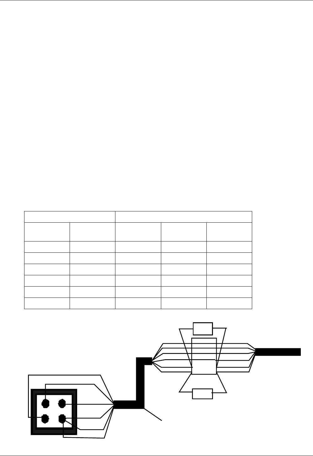
The following diagram is how we recommend that the cable is wired.
V+
VCA
V-
SIG
Red
White
Green
Blue
Black
Brown
Black
Green
Blue
Yellow
White
Red
Junction
Box
6-core alarm cable
to reader channel
on door controller
Black
Green
Blue
Brown
White
Red
Door
Contact
RTE
Suppression Cable

Reader Wiring
17063 Ver 1.6 DRAFT B 7 Easikey Readers
Notes
1. The ends of any cores not used on the suppression cable can be snipped off.
2. If the controller is an Easikey then there is no Door Contact option available and the
Brown core on the suppression cable is not used.
5.3 MOV - Lock Suppression
A metal-oxide-varistor (MOV) is provided with each reader. This device prevents back e.m.f.
('spikes') being returned from the electric lock to the controller. This can cause severe damage
over a period of time, and erratic operation of the system if not controlled.
A B
The MOV (A) should be fitted across the power terminals of the lock (B). It can be fitted across
the relay contacts on the controller, but this will be less effective.
Important Notice
If the reader is installed externally, then the terminals on the rear of the reader
MUST be sealed with a silicone compound to prevent corrosion.

Reader Wiring
17063 Ver 1.6 DRAFT B 8 Easikey Readers
Declaration of Conformity
Application of Council Directives 73/23/EEC
Standard(s) to which conformity is declared ETS 300.683
Manufacturer's Name PAC INTERNATIONAL LTD
Manufacturer's Address 1 Park Gate Close, Bredbury, Stockport, U.K. SK6 2SZ
Type of Equipment Access Control Systems
Product Equipment Easikey Reader Range
I, the undersigned, hereby declare that the equipment specified above conforms to the above directive(s) and
standard(s).
Signed Date 20th November 1995
Full Name Vanda Murray Position Managing Director