PAC P-FP Admin panel with low range proximity reader User Manual 15263
PAC International Limited Admin panel with low range proximity reader 15263
UserManual.wiki
>
PAC
>
P FP User Manual
Manual
Navigation menu
Upload a User Manual
Namespaces
Wiki Guide
HTML
PDF
Info
Views
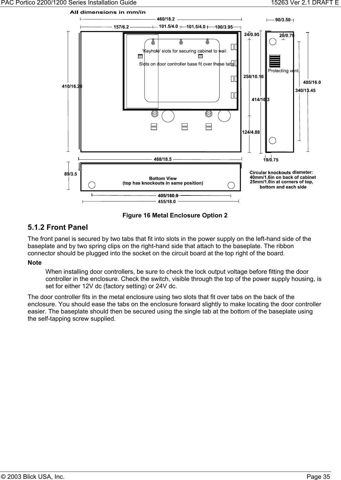
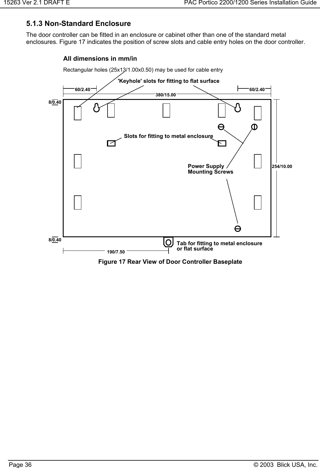
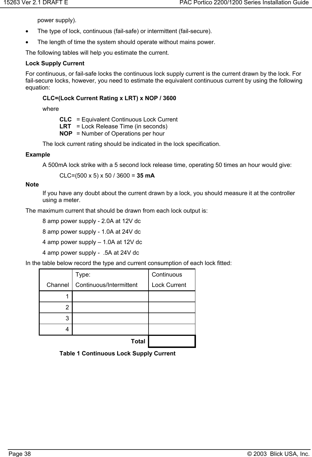
User Manual
Discussion / Help
Navigation