PAC P-PIN Low range proximity reader User Manual 15826jf
PAC International Limited Low range proximity reader 15826jf
PAC >
Manual
Data Sheet
January 2003 15826 Ver 1.8 DRAFT C
PAC Portico, 1 Lower Ragsdale Drive, Building 3, Suite 800, Monterey, California 93940 USA
www.PACPortico.com
This document is correct at the time of going to press. However, as part of our ongoing product enhancement program
we reserve the right to make changes to the product and/or literature at any time without prior notice.
PAC Portico PIN Reader Installation Guide
Surface and Flush Mounted
Introduction
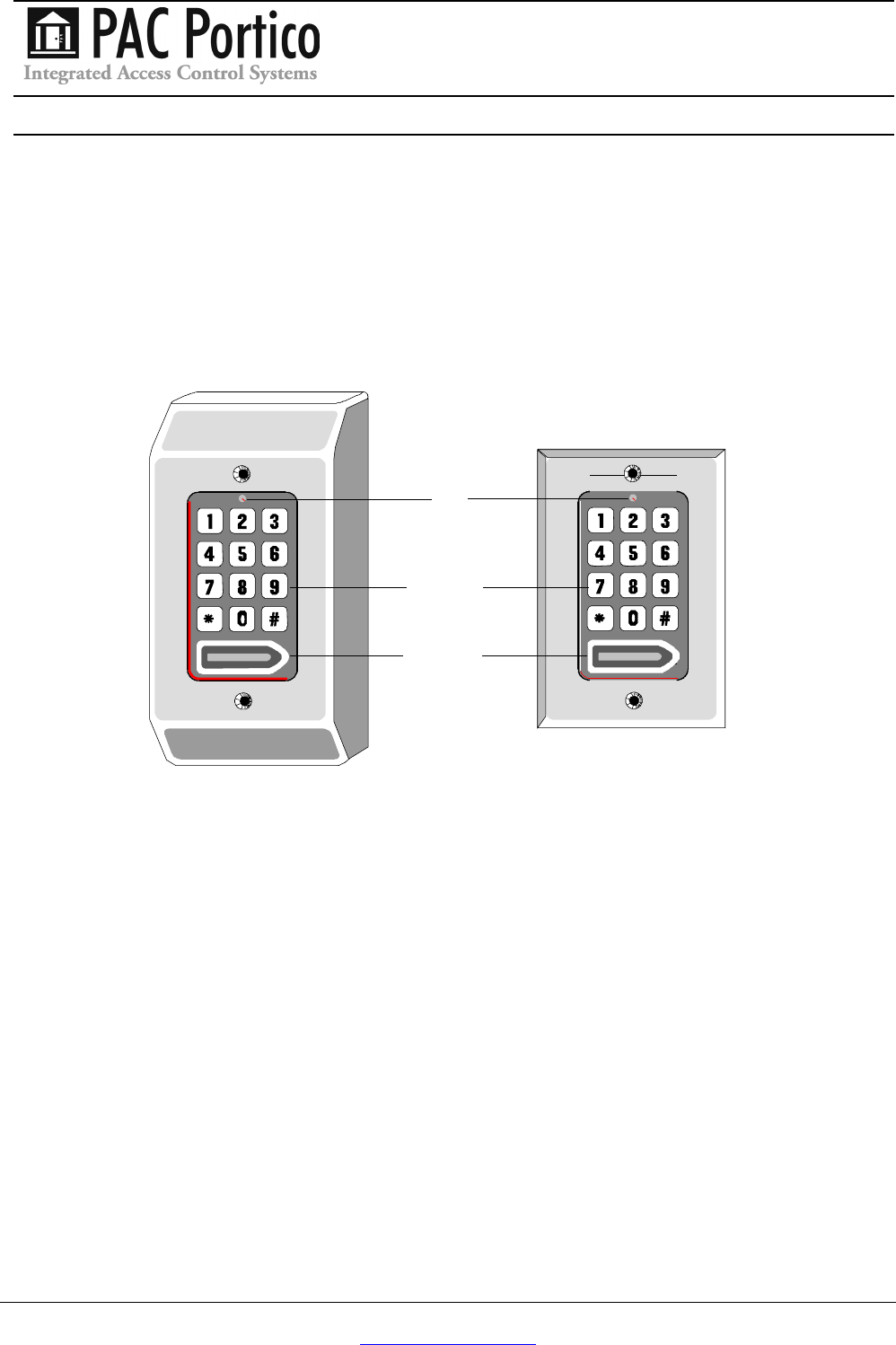
This data sheet describes the PAC Portico Surface Mounted PIN Reader and PAC Portico
Flush PIN Reader (pictured below).
Surface Mounted Flush Mounted
LED
KEYPAD
READER
Application
The PIN reader is of particular use in high security applications, having the extra security of a
Personal Identification Number (PIN) number as well as a PAC Portico key (or card). The use of
low cost, unscreened, signal alarm cable is recommended to connect the reader to the door
controller.
General Description and Operation
To gain access through a door the user must first present a valid PAC Portico key to the built-in
reader. Once the key has been read, the Light Emitting Diode (LED) will momentarily change
from red to green.
The user must then enter their 4-digit PIN number via the keypad. The LED will blink green and
the built-in sounder will beep as each key is pressed. Once the PIN has been entered, if the PIN
is correct, the LED will become green to indicate the door is unlocked.
If the PIN is incorrectly entered, four further attempts may be made to gain access (by re-
presenting the key and re-entering the PIN) before the individual key becomes locked out. The
lock-out is cleared when a different key is used.
Once a key becomes locked out, it remains locked out for 2 hours; this lock-out period will
expire when the key has not been presented to the reader during that 2 hour period. Using a
key when it has been locked out, will cause the lock-out period to be increased by 2 hours.
15826 Ver 1.8 DRAFT C PAC Portico PIN Reader Installation Guide
Page 2 © 2003 Blick USA, Inc
Example
If a locked out key is presented to a reader 10 minutes before its 2 hour period is
completed, the lock-out period will be extended to 2 hours 10 minutes.
A duress facility is available which may be activated by the user adding 1 to the last digit of their
PIN (i.e. PIN numbers of 1234 has a duress code of 1235). The duress code will open the door
and will also set off a predefined signal, such as an alarm (this feature will need to be
configured separately with a standalone system or through PAC Portico for Windows).
The use of a PIN number is optional and may be controlled by a time profile (i.e. at certain times
a key only may be required to gain access, at other times a key and PIN must be used).
Note
Each PIN number is derived from the key and cannot be changed.
The reader is not prone to electrical interference from normal electrical equipment, however
care should be taken to avoid mounting the reader and cables in close proximity to heavy load
switching cables and equipment.
The performance of the readers is unaffected by the material of the mounting surface but make
sure the mounting surface is as even as possible to provide maximum protection to the reader.
Try to mount the reader at a height which it is easy to operate at; a recommended height for an
able bodied person is 5.0-5.6ft/1.5-1.7m. Also the reader should be in a well lit place.
Reader Installation
It is not recommended to mount the reader externally but if it is installed externally, all
exposed terminals on the reader and the connector strip must be protected by a
proprietary sealant, e.g. silicone rubber compound. Use the reader as a template in order to
accurately mark the fixing points onto the mounting surface.
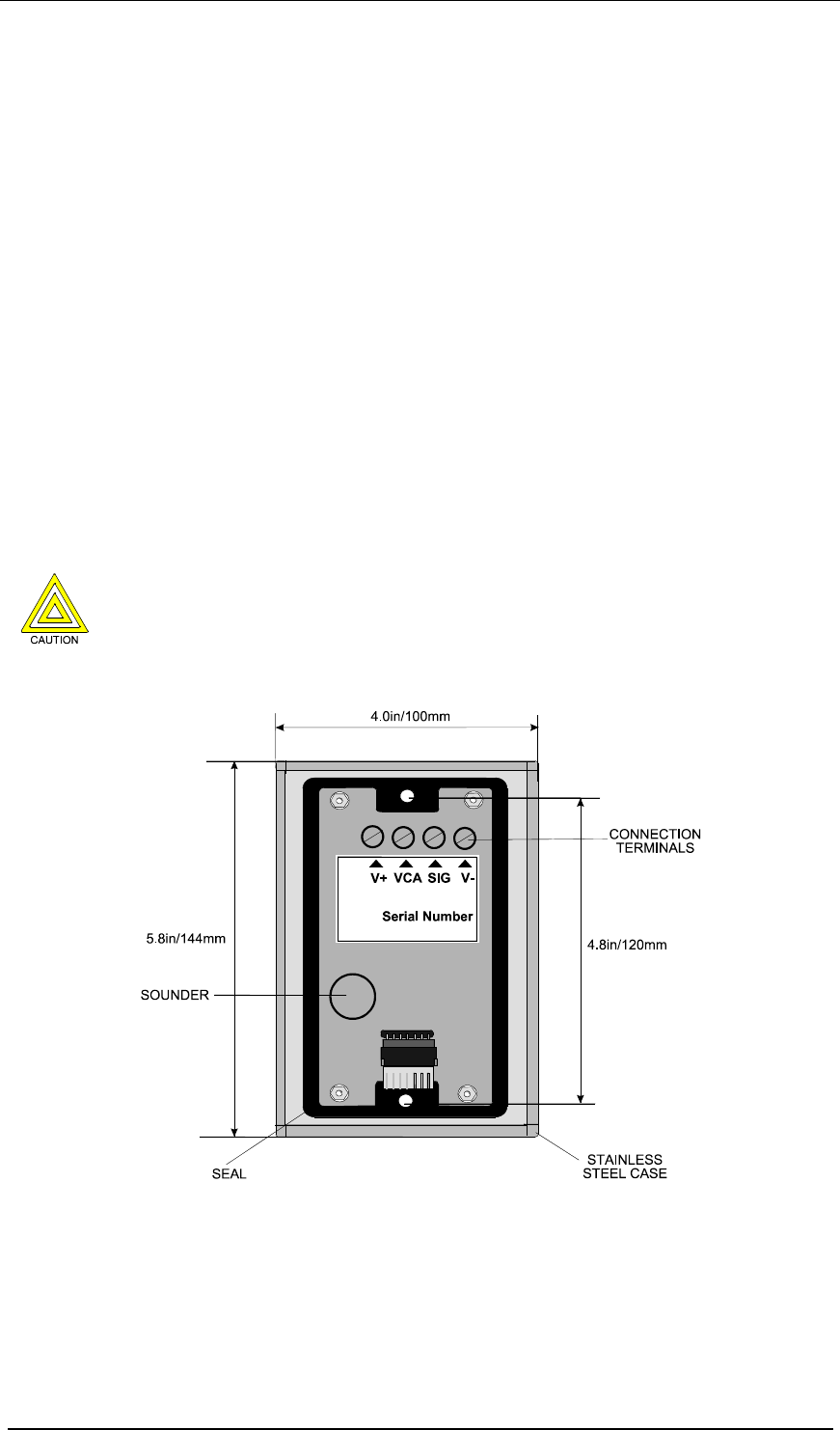
Flush Mounted
This reader is designed to be flush mounted onto a standard 2 gang (1.4in/35mm) back box using
the two M3.5 (1in/25mm x 0.14in/3.5mm) screws provided.
The connecting cable can be taken directly from the terminals through the knock-outs in the
back box via a suitable grommet and through a suitably prepared hole in the mounting surface.
The dimensions of the flush mounted reader are 4.0in/100mm x 5.8in/144mm.
PAC Portico PIN Reader Installation Guide 15826 Ver 1.8
DRAFT C
© 2003 Blick USA, Inc Page 3
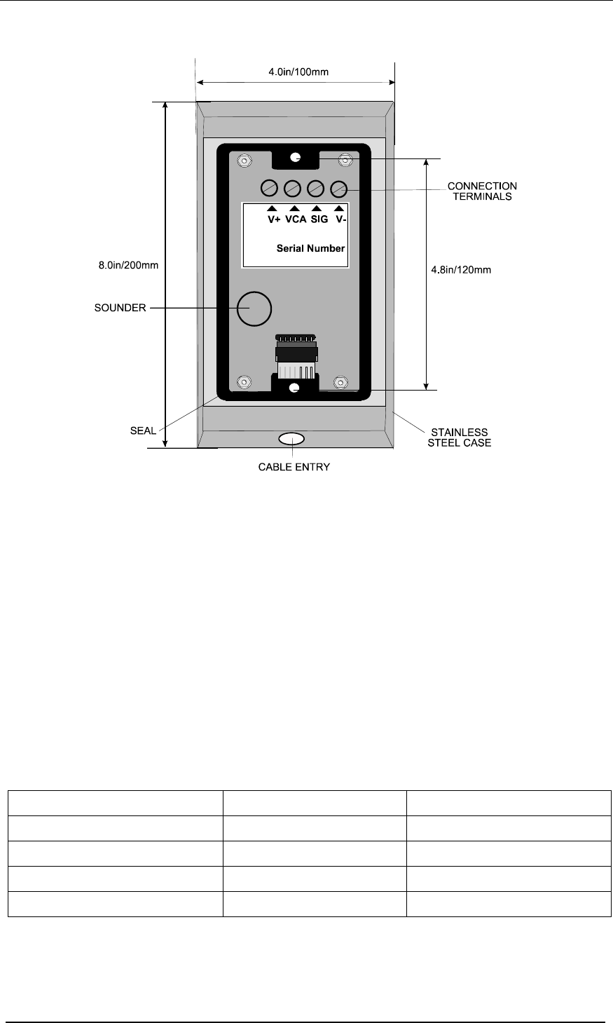
Surface Mounted
The reader is designed to be surface mounted onto a flat surface using the two holes provided,
therefore not requiring the installation of a back box. The readers performance is unaffected by
the material of the mounting surface. Ensure the surface is as even as possible to provide
maximum protection against the reader being levered from the wall.
The connecting cable can be taken via the hole provided on the lower section of the reader
housing and then surface mounted, preferably under the protection of a suitable conduit.
Alternatively, the cable could be taken directly from the terminals through a suitably prepared
hole in the mounting surface so as to be completely hidden from sight.
The holes are designed to accept size No.8 countersunk screws, preferably anti-tamper type, with
a recommended minimum length of 2in/50mm. This recommended length of course depends on
the surface type and construction.
The dimensions of the surface mounted reader are 8in/200mm x 4in/100mm x 1.3in/30mm.
Connections
Reader Connections
The connections for both readers are:
Color Signal Notes
Black 0V Negative supply
White SIG Reader signal
Brown VCA Valid code accept LED
Red +12V Positive supply

15826 Ver 1.8 DRAFT C PAC Portico PIN Reader Installation Guide
Page 4 © 2003 Blick USA, Inc
Cable Lengths
The cross-sectional area determines the cable length:
Cable Gauge Easikey PAC 2100
Series
PAC 2200
Series
PAC 202
24AWG/0.22mm2240ft/80m 325ft/200m 66ft/20m
20AWG/0.5mm2550ft/180m 1500ft/500m
18AWG/1.0mm23000ft/1000m 2250ft/700m
Specification
• Keypad: 10-digit rigid membrane keypad with visual target area for key presentation.
• LED Indicator: Red LED flashing momentarily to green showing electronic key acceptance
and PIN code entry, continuous green indicates correct code entry.
• Reader range: 0-0.6in/0-15mm.
• Supply voltage: 12-18V dc (supplied from controller).
• Cable: 4 or 6-way (4 required for reader) multi-stranded, unscreened standard signal/alarm
cable.
• Environment: Temperature: -49°F to 122°F (-45°C to 50°C).
• Relative Humidity: 0 to 90% non-condensing.
• MeanTime Between Failures: >100,000 hours
RFID Devices
As similar RFID technology is now widely used in a number of other industries, for example
automotive immobilisers, it is possible that interaction between your access control credential
and other devices may cause one or the other to function incorrectly. Should you suspect that
you have experienced such a problem the solution is to separate your access control credential
from other RFID devices.
FCC
This device complies with part 15 of the FCC rules. Operation is subject to the following two
conditions (1) this device may not cause harmful interference, and (2) this device must accept
any interference received, including interference that may cause undesired operation.
Surface Mount FCC ID OQL-P-S-PIN
Flush Mount FCC ID OQL-P-PIN
Changes or modifications not expressly approved by the party responsible for compliance could
void the user's authority to operate the equipment.