PAC P-PNL Low range proximity reader User Manual 15729
PAC International Limited Low range proximity reader 15729
PAC >
Manual
Data Sheet
January 2003 15729 Ver 1.5 DRAFT D
PAC Portico, 1 Lower Ragsdale Drive, Building 3, Suite 800, Monterey, California 93940 USA
www.PACPortico.com
This document is correct at the time of going to press. However, as part of our ongoing product enhancement program
we reserve the right to make changes to the product and/or literature at any time without prior notice.
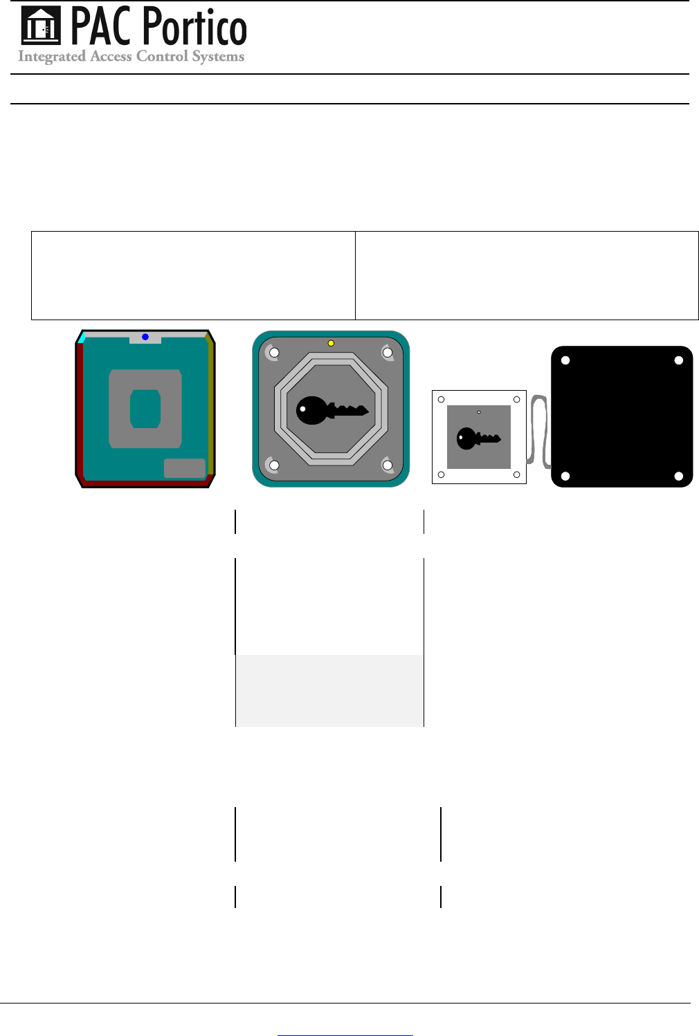
PAC Readers
Low Profile, Vandal Resistant and Panel Mount
2001 Low Profile Reader-Black
2001W Low Profile Reader-White
2002 Vandal Resistant Reader-Steel
2002W Vandal Resistant Reader-Brass
2025 Panel Mount Reader
CAUTION
These readers should only be used with systems that
use PAC ID keys. For example, they should not be
connected to an Easikey controller.
Low Profile Vandal Resistant Panel Mount
Items Enclosed
Low profile reader Vandal resistant reader Panel mount reader and head
4 terminal screws 4 terminal screws 4 terminal screws
MOV MOV MOV
Mounting backplate 4 x 1¼" No. 8 VR screws Lexan window and backplate
Label
2 x 1" No.6 self-tapping
screws
A special screwdriver
(available separately) is
required for the Vandal
Resistant (VR) screws.
Note
The readers come with a 6-wire suppression lead that should be installed as described in
this datasheet. This cable must be installed to comply with CE regulations.
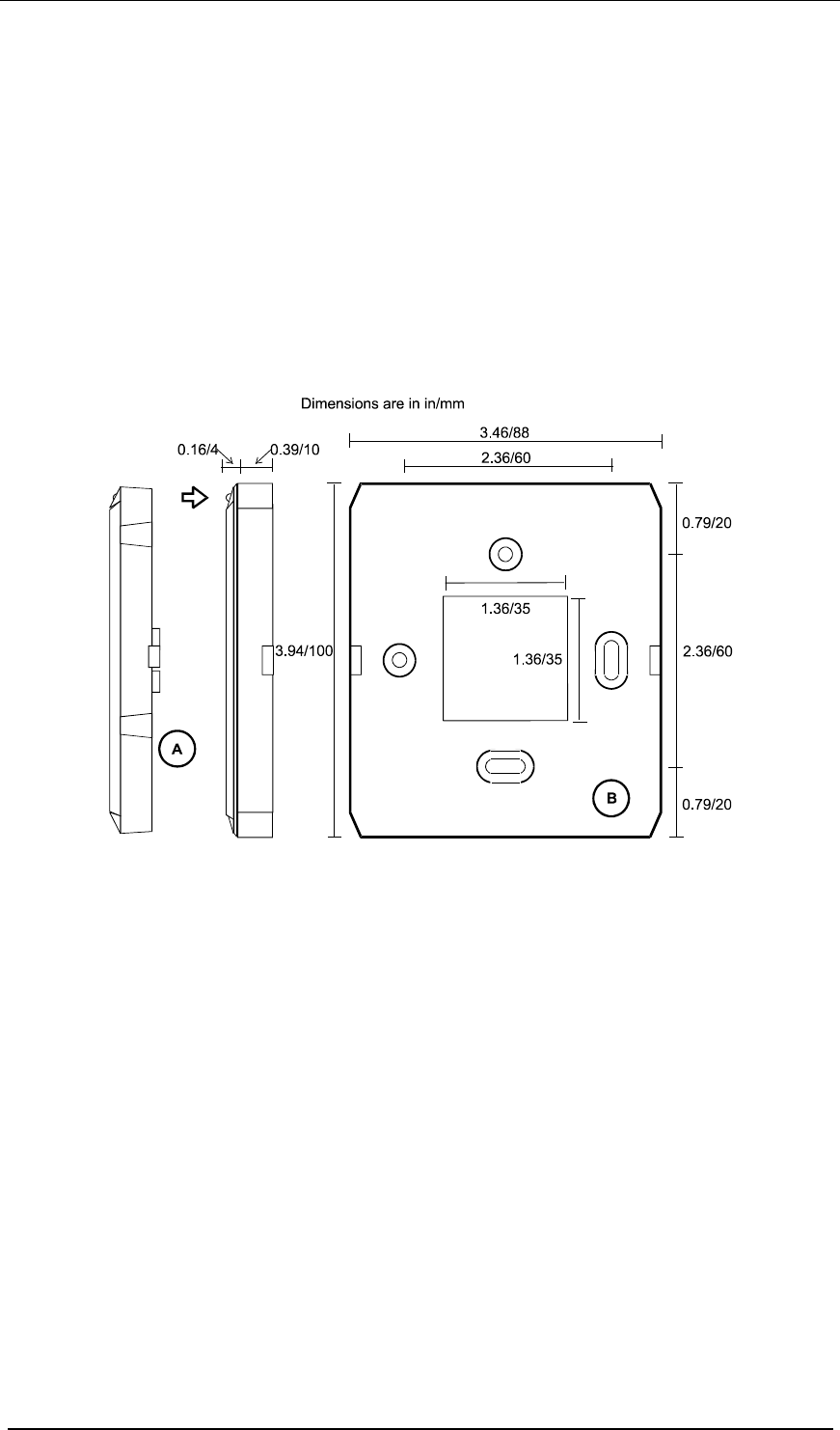
Dimensions
H x W x D in/mm
3.94/100 x 3.46/88 x 0.47in/12
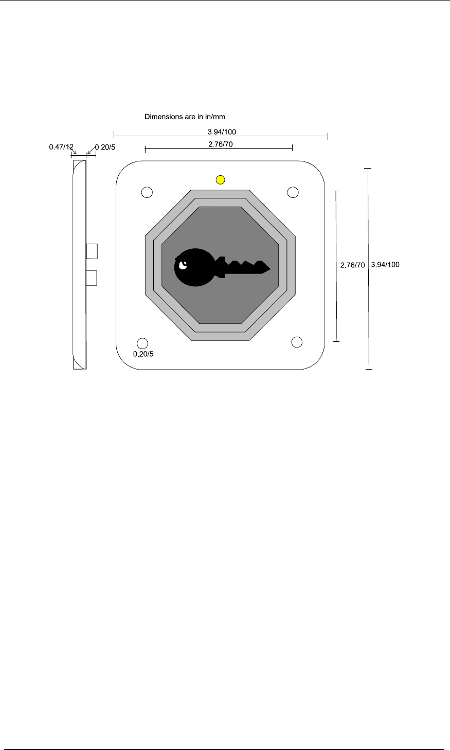
H x W x D in/mm
3.94/100 x 3.94/100 x 0.47/(12
H x W x D in/mm
3.62/92 x 2.44/62 x 0.59/15 Reader
2.36/60 x 2.36/60 x 0.47/12 Head
Maximum Reading Range
2in/50mm 0.4in/10mm 0.4in/10mm
15729 Ver 1.5 DRAFT D PAC Readers Low Profile, Vandal Resistant and Panel Mount
Page 2 © 2003 Blick USA, Inc
Installation
CAUTIONS
1. The readers should not be mounted on metal.
2. The cable distance from controller to reader should not exceed the cable distance
quoted in Section 0.
3. If using a Request to Exit switch, ensure that the wiring is not accessible if the reader
is removed.
4. Ensure that the LED is always visible to the key holder.
5. If the reader is installed externally, the terminals on the rear of the reader must be
sealed with a silicone compound to prevent corrosion.
Low Profile Readers
This reader comes in two parts, the reader itself (A) with 4 terminals and the backplate (B). The
backplate has a rubber spacer at the rear.
Mounting the Reader
1. The cable from the controller should be routed through the hole in the backplate. Leave
enough cable exposed to allow easy wiring of the reader (at least 1 inch).
Note: There is limited room between the reader and backplate. You should ensure there is
a void large enough behind the backplate to accommodate the any excess on the
suppression cable.
2. Mount the backplate to a flat surface using the No.6 screws provided - or a something
suitable for the material to which the reader is being mounted. The two holes are 60mm
apart. Use the top (round) hole first, and the lower (oval) hole to ensure the reader is
straight.
3. Ensure that the reader cable is not connected to the controller. Wire the reader to the cable
as described later in this data sheet and in the door controller Installation Manual
4. Push the reader, with the green LED to the top, onto the backplate, the fixing tabs on each
side should snap into place.
5. Place label on front of reader.
PAC Readers Low Profile, Vandal Resistant and Panel Mount 15729 Ver 1.5
DRAFT D
© 2003 Blick USA, Inc Page 3
Removing the Reader
The reader can be removed from the backplate by placing a small flat-bladed screwdriver into
the apertures on each side of the backplate. Take care not to damage the reader or backplate.
Vandal Resistant Readers
This reader should be mounted using the vandal resistant screws provided.
Note
A special screwdriver (not supplied) is required to use these screws.
Mounting the Reader
1. The cable from the controller should come to the rear of the reader. Leave enough cable
exposed to allow easy wiring of the reader (at least 1 inch).
Note: The terminals protrude ¼ in from the rear of the reader. You should ensure there is
a void large enough (about 1 ½ in square and ¾ in deep) behind the reader to
accommodate the terminals and excess suppression cable.
2. Ensure that the reader cable is not connected to the door controller. Wire the reader to the
cable as described later in this data sheet and in the door controller Installation Manual.
3. Apply a silicone sealant to the terminals to protect against moisture if the reader is
mounted outside.
4. Mount the reader to as flat and even a surface as possible. This will reduce the possibility
of it being levered from the wall. Either use the Vandal Resistant screws provided, or other
suitable fixings. The LED should be to the top.
15729 Ver 1.5 DRAFT D PAC Readers Low Profile, Vandal Resistant and Panel Mount
Page 4 © 2003 Blick USA, Inc
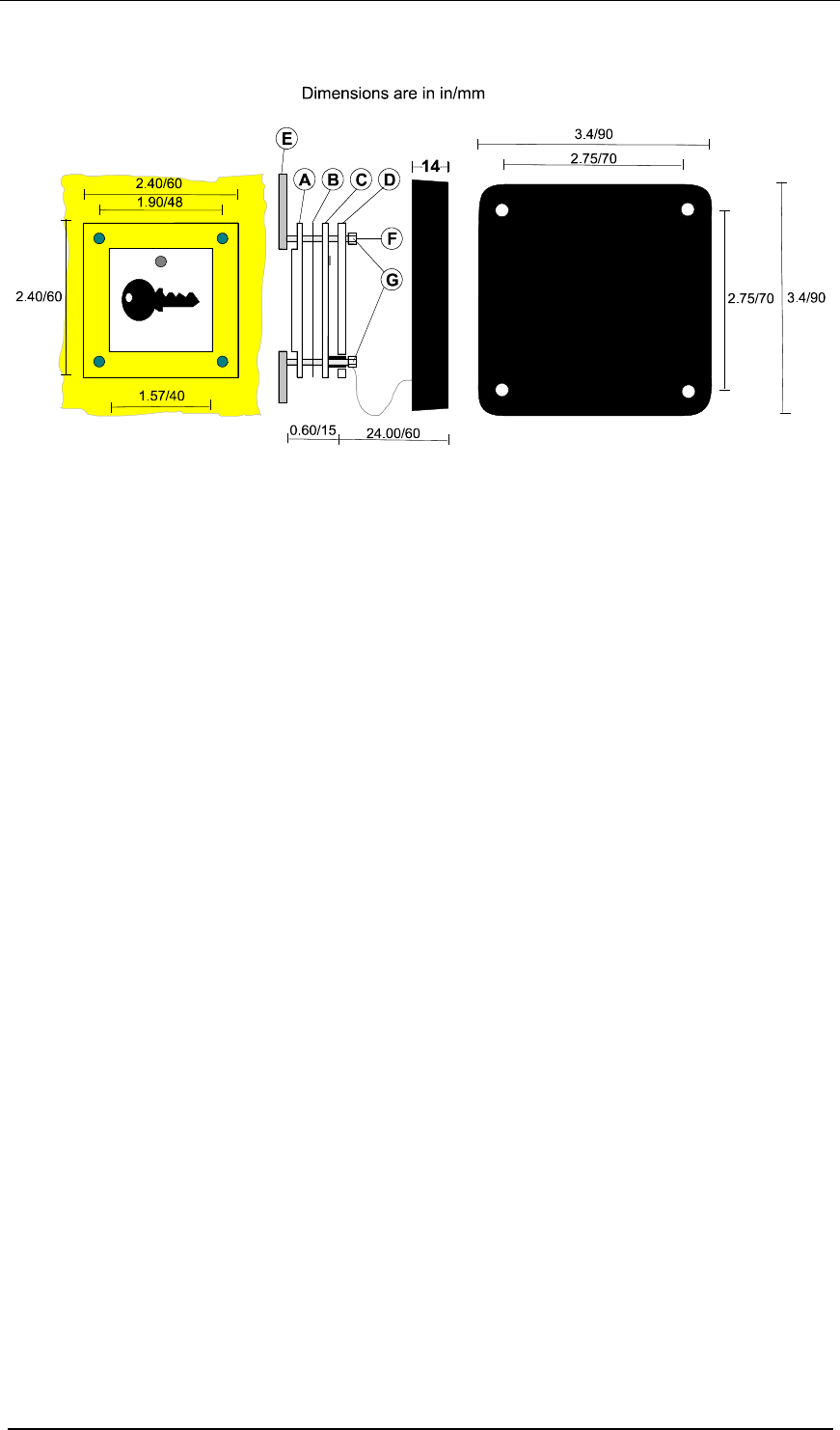
Panel Mount Reader
This reader is designed to be mounted in a steel panel (E) such as used in a door-entry system.
There are two main units; the main module, a black rectangular unit, connected by a fixed
length of cable to a reading head. The cable between the two parts is fixed, 24in/60mm long
and should not be cut, extended or shortened.
Panel Aperture
The reading head is designed to fit a 1.57in/40mm square hole. Holes on the reading head,
1.89in/48mm between centres, accept M3 (metric) posts (F). The posts should be at least
0.59in/15mm long. The front cover (A) protrudes 0.10in/2.5mm through the hole.
Locating the Main Module
Mount the module in a convenient place behind the panel. The holes in each corner will accept
No. 6 screws. Ensure that the module is close enough to the reader head to allow the panel to
be removed without straining the cable. Wire the reader as seacribed in Section 0. Ensure there
is sufficient space for any excess sppression cable.
Mounting the Reading Head
There are 4 components to the reading head:
1. Remove the protective film from the front lexan window (A). Mount on the studs so that the
centre fits through the aperture, with the shallow slot to the bottom.
2. Remove the backing from the label, and fit to the circuit board (C), the clear hole should
align with the green LED.
3. Place the circuit board (C) and label over the studs against the window with the cable facing
away from the aperture.
4. Fit the rear lexan cover (D) and clamp using screws suitable for the studs (G).
PAC Readers Low Profile, Vandal Resistant and Panel Mount 15729 Ver 1.5
DRAFT D
© 2003 Blick USA, Inc Page 5
Reader Wiring
Notes
1. The wiring and location of readers is described in the documentation supplied with the
door controller. All the readers described in this datasheet have identical terminals.
2. If connected to a PAC 2100 Series Door Controller, it is strongly recommended that a
100mA in-line fuse is installed in line with the reader supply.
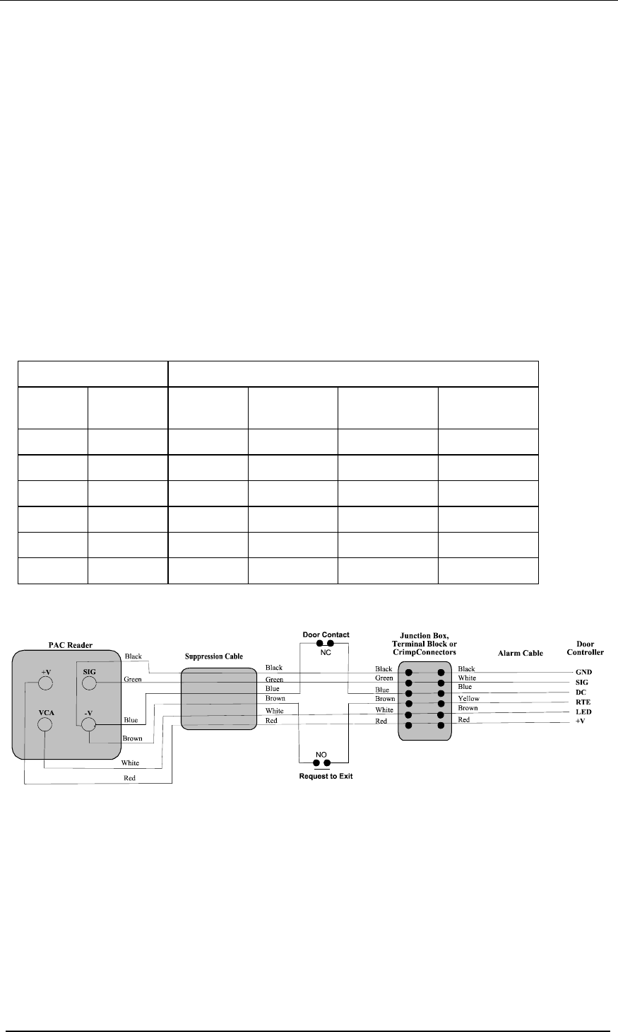
Connecting the Suppression Cable
One end of the 6-conductor suppression cable is connected to the reader and the other is
connected to the cable connected to the reader channel on the controller. The suppression
cable comes with four spade crimps at one end for easy connection to the terminals on the
reader. Crimp wire joints are provided for connection to the reader cable from the controller.
The following table details suppression cable connections to both the reader and to the reader
cable from the controller.
Note
Care must be taken if a different colour convention for the controller reader cable is used
than that given in the table.
Suppression Cable Controller Reader Cable
Colour Reader Colour PAC 2100
Series
PAC 2200
Series
PAC 202
Black -V Black GND GND 0V
Green SIG White SIG SIG1/SIG2 SIGA/SIGB
Blue -V Blue DR1 DC/DR1 DC
Brown -V Yellow DR2 RTE/DR2 RTE
White VCA Brown LED LED LED
Red +V Red +18V +18V +V
The following diagram is how we recommend that the cable is wired.
15729 Ver 1.5 DRAFT D PAC Readers Low Profile, Vandal Resistant and Panel Mount
Page 6 © 2003 Blick USA, Inc
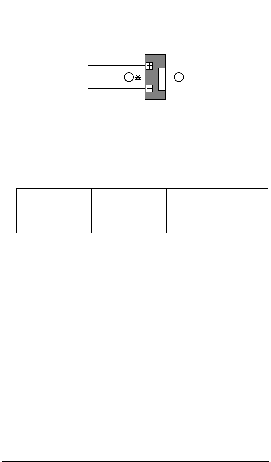
MOV - Lock Suppression
A Metal-Oxide-varistor (MOV) is provided with each reader. This device prevents back EMF
('spikes') being returned from the electric lock to the controller. This can cause severe damage
over a period of time, and erratic operation of the system if not controlled.
A B
The MOV (A) should be installed across the power terminals of the lock (B). It can be fitted
across the relay contacts on the door controller, but this will be less effective.
Specification
Operating Temperature: -40°C to +50°C
Current: 100mA (maximum)
Supply Voltage: 18V dc
Cable Type: 4 or 6-conductor, stranded, unshielded
Cable Gauge and Distances:
Cable Type PAC 2100 Series PAC 2200 Series PAC 202
24AWG/0.22mm² 7/0.2 750ft/250m 750ft/250m 230ft/70m *
20AWG/0.5mm² 16/0.2 1500ft/500m 1500ft/500m
18AWG/1.0mm², 32/0.2 3000ft/1000m 3000ft/1000m
* These figures are for readers powered from the controller. The cable distances can be
increased to 1650ft/500m by locally powering the readers.
Mean Time Between Failures: >100,000 hours
RFID Devices
As similar RFID technology is now widely used in a number of other industries, for example
automotive immobilisers, it is possible that interaction between your access control credential
and other devices may cause one or the other to function incorrectly. Should you suspect that
you have experienced such a problem the solution is to separate your access control credential
from other RFID devices.
FCC
This device complies with part 15 of the FCC rules. Operation is subject to the following two
conditions (1) this device may not cause harmful interference, and (2) this device must accept
any interference received, including interference that may cause undesired operation.
Low Profile FCC ID HM3D8201
Vandal Resistant FCC ID OQL-P-VN
Panel Mount FCC ID OQL-P-PNL
Changes or modifications not expressly approved by the party responsible for compliance could
void the user's authority to operate the equipment.