PAC R-VN Vandal Resistant Reader User Manual T81153 14104 Readers
PAC International Limited Vandal Resistant Reader T81153 14104 Readers
PAC >
Manual

Designer and Vandal-Resistant Readers
Installation Guide
Designer und Vandal-Resistant Lesers
Installationsanleitung
Designer et Vandal-Resistant Lecteurs
Guide d'installation
Designer y Vandal-Resistant Lectores
Guía de instalación
Designer och Vandal-Resistant Läsare
Installationsanvisningar
Designer en Vandal-Resistant Lezers
Installatiehandleiding
T81153v2.2
14104 Mar 05
2 T81153v2.2
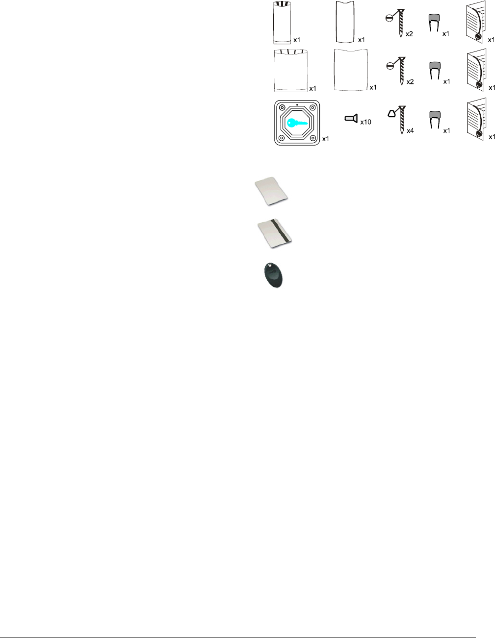
Reader Part Numbers / Leser Teilnummern / Numéros de pièces du lecteur / Números de pieza del
lector / Läsarens Artikelnummer/ Lezer Productnummers
black/
schwarz/
noir/
negro/
svart/
zwart
grey/
grave/
grise/
grid
white/
weiß/
blanc/
blanco/
vit/
wit
Mullion Designer
21N-MPR-
BLACK
21N-MPR-
GREY
21N-MPR-
WHITE
Standard Designer
21N-SPR-
BLACK 21N-SPR-
GREY 21N-SPR-
WHITE
Vandal-Resistant
21N-VPR-SS
Card/Token Part Numbers / Karten/Token Teilnummern / Numéros de pièces de carte/fiche / Números
de pieza de la tarjeta/ficha / Kort/Nyckel Artikelnummer / Passen/Penningen Productnummers
Card/Karten/Kort/Passen
x10
11N-PT-10
With Magstripe//Mit Magnetstreifen/avec bande magnétique/
Con banda magnética/med magnetremsa
x10
11N-MPT-10
Token/Nyckel /Penningen
x10
11N-FPT-10
Specification / Spezifikation / Spécification / Especificaciones / Specifikation / Specificaties / 技术规格
Card Range Token Range Power Current
Mullion Designer up to 3.5in/90mm up to 1.9in/50mm +10.5 to +28V <100mA
Standard Designer up to 7.8in/200mm up to 1.9in/50mm +10.5 to +28V <100mA
Vandal-Resistant up to 1.9in/50mm up to 1.9in/50mm +10.5 to +20V <85mA
Temperature / Temperatur / Température / Temperatura / Temperatur / Temperatuur
Operating -3 to 130ºF/-20 to +55ºC; Storage -35 to175ºF/-30 to +80ºC
Humidity / Feuchtigkeit / Humidité / Humedad / Luftfuktighet / Vochtigheid
Operating 10 to 85% RH at 85 ± 4ºF/30 ± 2ºC for 24 hours
Ingress Protection / Eindringschutz / Protection contre l'entrée / Protección de acceso / Kapsling /
Stofbescherming
IP 66
FCC
Mullion Designer FCC ID OQL-R-DM
Standard Designer FCC ID OQL-R-DS
Vandal-Resistant FCC ID OQL-R-VN
This device complies with part 15 of the FCC Rules. Operation
is subject to the following two conditions: (1) This device may
not cause harmful interference, and (2) this device must
accept any interference received, including interference that
may cause undesired operation.
In compliance with FCC requirement 15.27 no special accessories are required in order to comply with part
15 of the FCC regulations.
Changes or modifications not expressly approved by Stanley Security Solutions could void the user's
authority to operate the equipment.
T81153v2.2 3
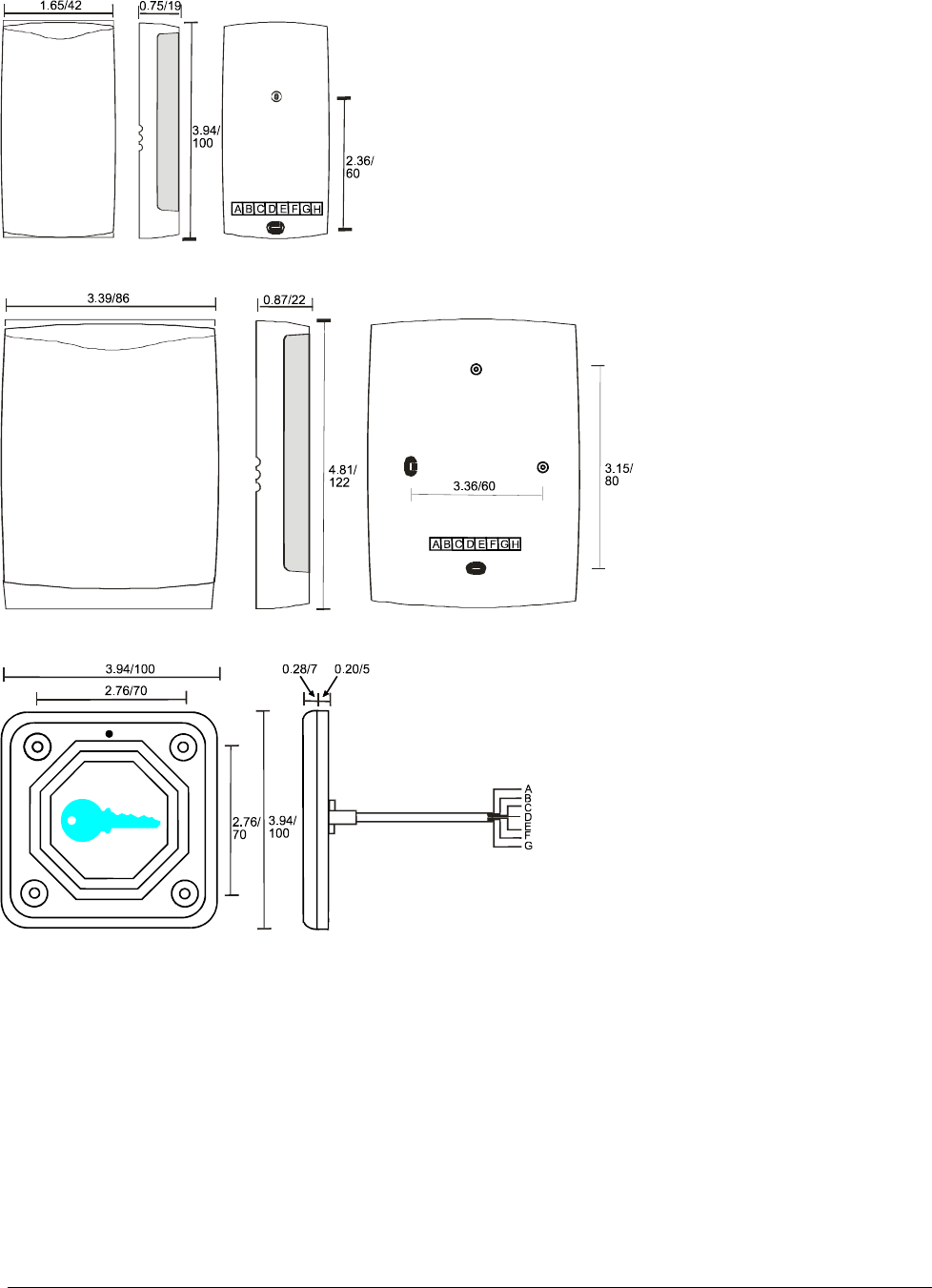
Connections/ Anschlüsse / Connexions / Conexiones / Anslutningar / Voedingsaansluitingen
All dimensions ins/mm / Alle Ausmaße in zoll/mm / Toutes dimensions en pce/mm / Todas las dimensiones
en pulg./mm /Alla mått i tum/mm / Alle afmetingen inch/mm
Mullion Designer
A 10.5-28V (10.5-20V for Vandal-Resistant)
B SIG/D1/DATA/SIGNAL
C LED
D GND/0V
E D0/CLK
F Tamper/Sabotage/Effraction/Manip.fraud./Manip/Tamper
G Sounder/Signaltongeber/
Alarme sonore/Sonido/Ljudsignal/Alarm
H Not used/Nicht verwendet/N'est pas utilisé/
No se utiliza/Används inte/Niet gebruikt
Standard Designer
Vandal-Resistant
A Red/Rot/Rouge/Rojo/Röd/Rood
B White/Weiß/Blanc/Blanco/Vit/Wi
C Brown/Braun/Marron/Marrón/Brun/Bruin
D Black/Schwarz/Noir/Negro /Svart/Zwart
E Green/Grün/Vert/Verde/Grön/Groen
F Blue/Blau/Bleu/Azul/Blå/Blauw
G Yellow/Gelb/Jaune/Amarillo/Gul/Geel
Output Format Selection / Wahl des Ausgabeformats / Sélection de format de sortie / Selección de
formato de salida / Val av utdataformat / Selectie van uitvoerformaat
Connections/Anschlüsse/
Verbindingen/Conexiones/
Anslutningar/ Connexions
No. of flashes/ Zahl der Blinkvorgänge/
Nb. de clignotements/ Núm. de
destellos/Aantal flitsen/
Antal blinkningar
Stanley (default/vorgabe/
standaard/por defecto) C-B - 0
Wiegand 26-bit C-E - 1
Wiegand 34-bit C-B G-E 2
Magstripe/gnetstreifen/
magnetremsa - G-E 4
Barcode C-E G-B 5

4 T81153v2.2
Installation
1. Ensure your product comes with the items indicated on page 2; if not please contact your dealer.
2. Mounting on metal surfaces will reduce the reader range.
3. Mount readers >3ft/1m apart.
4. For outside readers, use corrosion-resistant fasteners and silicone sealant on terminals.
5. The Metal Oxide Varistor (MOV) should be fitted across the power terminals of the lock.
6. After installation of a Designer Reader, fill the connector well with silicone to seal it. Stanley recommend
a high-quality sealant like Dow Corning Type 732.
Output Format Selection
1. Short together the connections indicated in the table on page 3.
2. Apply power for 2 seconds
3. Separate all connections.
4. Re-apply power.
5. LED flashes to indicate ouput format set in the table on page 3.
Installation
1. Überprüfen Sie, ob Ihr Produkt die einzelteile angezeigt auf Seite 2. Wenn nicht, wenden Sie sich bitte
an Ihren Händler.
2. Die Befestigung an den Metalloberflächen verringert die Leserstrecke.
3. Leser im Abstand von > 3 Fuß/1 m anbringen.
4. Für Leser im Freien korrosionsbeständige Befestigungselemente und Silikondichtungsmittel an den
Anschlüssen verwenden.
5. Der MOV sollte über die Stromanschlüsse des Schlosses angebracht werden.
6. Nach der Installation von einnem Designer Leser, den Stecker vollständig mit Silikon füllen, um ihn zu
versiegeln. Stanley empfehlen ein hochwertiges Dichtungsmittel wie Dow Corning Art 732.
Wahl des Ausgabeformats
1. Die Anschlüsse wie auf der nachfolgenden Tabelle angegeben auf Seite 3 miteinander kurzschließen.
2. 2 Sekunden lang Strom anlegen.
3. Alle Anschlüsse trennen.
4. Nochmals Strom anlegen.
5. Die LED Blitze, zum des ouput Formats anzuzeigen stellten in die Tabelle auf Seite 3 ein.
Installation
1. Vérifiez que votre produit contient toutes les articles indiqués à la page 2. En cas de pièce manquante ,
contactez votre distributeur
2. Le montage sur des surfaces en métal réduira la gamme de lecteur.
3. Monter les lecteurs à de telle sorte qu'ils soient espacés d'1 m.
4. Pour les lecteurs extérieurs, utiliser des fixations résistantes à la corrosion et du silicone sur les bornes.
5. Le MOV (varistor à oxyde métallique) doit être installé en travers des bornes d'alimentation du verrou.
6. Après l'installation d'un Designer Lecteur, bien remplir le connecteur de silicone pour l'étanchéiser.
Stanley recommandent un mastic de haute qualité comme le Dow Corning type 732.
Sélection de format de sortie
1. Court-circuiter les connexions indiquées dans le tableau à la page 3.
2. Mettre sous tension pendant 2 secondes.
3. Séparer toutes les connexions.
4. Mettre à nouveau sous tension.
5. Les flashes de LED pour indiquer le format d'ouput ont placé dans la table à la page 3.
English
Deutsch
Français

T81153v2.2 5
Instalación
Asegure que el producto se suministra con los artículos artículos indicados en la página 2; en caso contrario,
rogamos que se ponga en contacto con el vendedor.
1. El montar en superficies del metal reducirá la gama del lector.
2. Monte los lectores a una distancia entre sí >1 m.
3. Para los lectores exteriores, utilice fijaciones anticorrosivas y sellador de silicona en las terminales.
4. El varistor de metal-óxido se debería montar a través de los terminales de potencia de la cerradura.
5. Tras la instalación de un Designer Lector, rellene bien el conector con silicona para sellarlo. Stanley
recomiendan un sellante de alta calidad como el Dow Corning tipo 732.
Selección de formato de salida
1. Puntee las conexiones que se indican en la tabla en la página 3.
2. Aplique potencia durante 2 segundos
3. Separe todas las conexiones.
4. Vuelva a aplicar potencia.
5. Los flashes del LED para indicar formato del ouput fijaron en la tabla en la página 3
Installation
1. Kontrollera att din produkt åtföljs artikeln antyd på sida 2. Kontakta din återförsäljare om.
2. Monteringen på metall utsidorna vilja reducera läsaren ställa i rad.
3. Montera läsarna mer än 1 meter isär.
4. För utomhusläsare ska korrosionståliga fästanordningar och silikontätningar användas på terminalerna.
5. Metalloxidvaristorn ska monteras över låsets spänningsanslutningar.
6. Fyll kontakten allra Design Läsare, ordentligt med silikon efter installationen för att täta den. Stanley
rekommendera en hög - kvalitet sätta sigill på lik Dow Corning typ 732.
Val av utdataformat
1. Kortslut anslutningarna som anges i tabellen på sida 3.
2. Aktivera spänningsmatningen under 2 sekunder.
3. Separera alla anslutningar.
4. Lägg på spänningsmatningen igen.
5. LED blinkar till ange ouput formaten sätta inne borden på sida 3.
Installatie
1. Controleer of met het product de punten die op pagina 2 worden vermeld. Indien dit niet het geval is,
neem dan contact op met de leverancier.
2. Het opzetten op metaaloppervlakten zal de lezerswaaier verminderen.
3. Plaats de sensors minstens 1 m uit elkaar.
4. Voor sensors die buiten worden gemonteerd dienen corrosiebestendige bevestigingsmiddelen en een
siliconen afdichtmiddel op de aansluitpunten gebruikt te worden.
5. Breng de MOV over de aansluitingen van het slot aan.
6. Na het installeren van een Designer Lezer, dient u de holte van het verbindingsmiddel met
siliconenafdichtmiddel op te vullen. Stanley adviseert een dichtingsproduct van uitstekende kwaliteit
zoals Dow Corning Type 732.
Selectie van uitvoerformaat
1. Sluit de verbindingen aan volgens de tabel op pagina 3.
2. 2 seconden onder stroom zetten
3. Alle verbindingen losmaken.
4. Nogmaals onder stroom zetten.
5. De LED flitsen om ouput op formaat te wijzen plaatsen in de lijst aangaande pagina 3.
Español
Svensk
Nederlands

6 T81153v2.2

T81153v2.2 7

© 2005 Stanley Security Systems, Inc.
www.stanleysecuritysolutions.com
Contact your local Stanley Security Solutions Systems Integration Office for Technical Support.
Stanley Security Solutions, Inc.
6161 E. 75th St.
Indianapolis, IN 46250
T: (317) 849-2250
Stanley Security Solutions - Europe Ltd
Blick House
Bramble Road
Swindon, SN2 8ER
T: +44 1793 692401
Stanley Security Solutions - Europe Ltd
Blick France
15 rue du 1er Mai
92752 Nanterre Cedex
T: 01 47 60 02 70
Stanley Technology Co Ltd
1/F, Building E
Zone A
Hongfa Industrial Park
Shi Yan Bao'an District
Shenzhen 518108
T: +86 755 29833111