PARKEON STRADA-BNA PAY AND DISPLAY MACHINE User Manual 08 user s manual
PARKEON PAY AND DISPLAY MACHINE 08 user s manual
UserManual.wiki
>
PARKEON
>
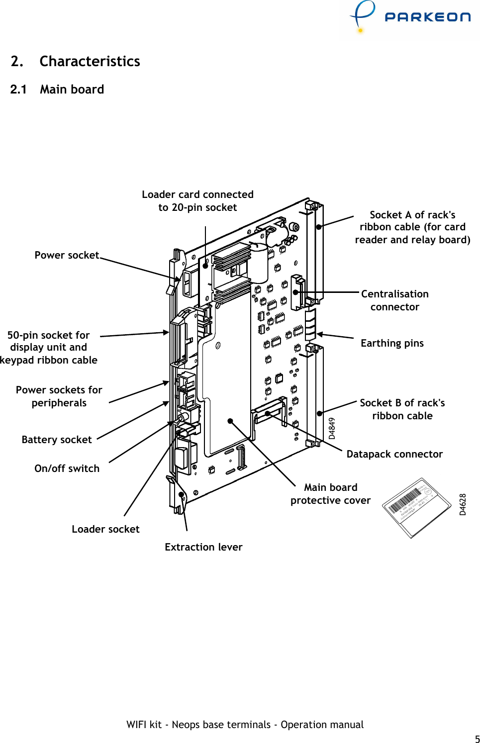
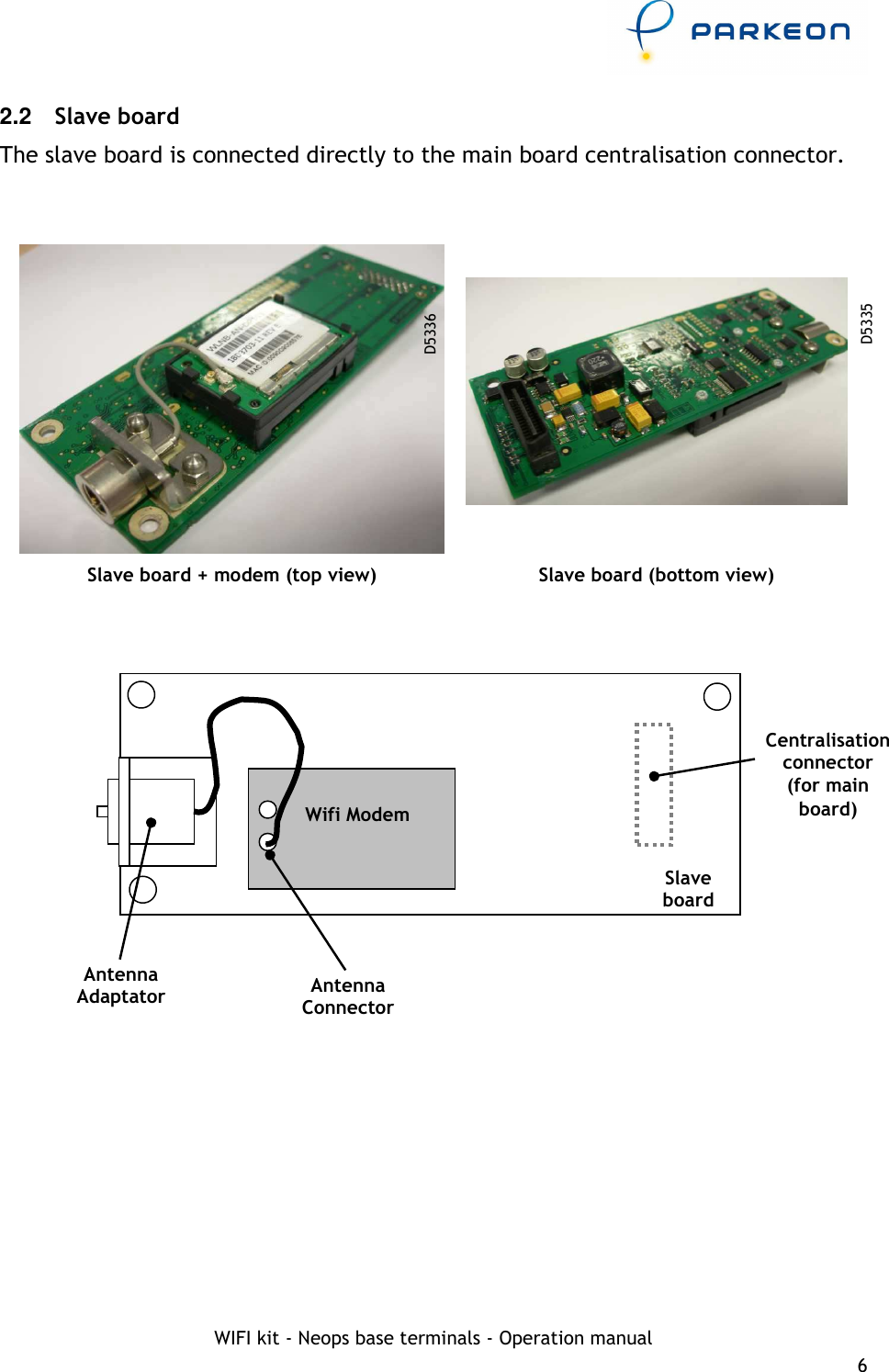
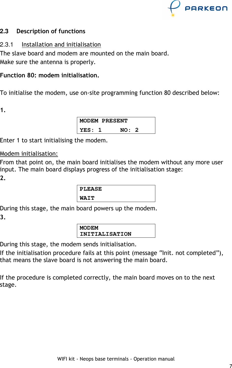
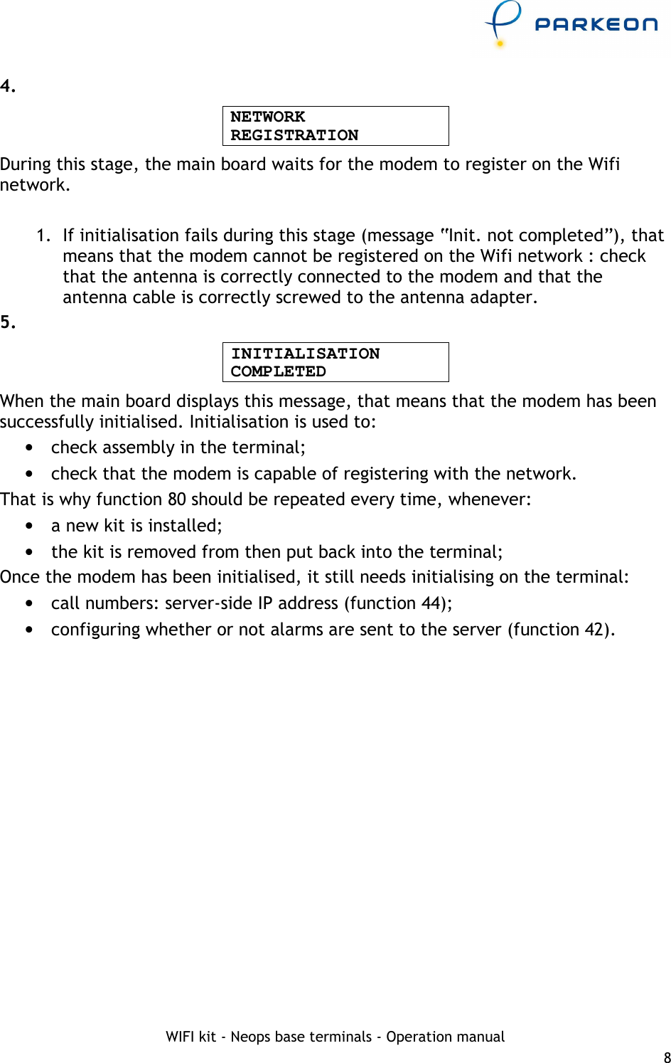
STRADA BNA User Manual
USERS MANUAL
Navigation menu
Upload a User Manual
Namespaces
Wiki Guide
HTML
PDF
Info
Views
User Manual
Discussion / Help
Navigation