PARKEON STRADA-BNA PAY AND DISPLAY MACHINE User Manual 08 user s manual
PARKEON PAY AND DISPLAY MACHINE 08 user s manual
PARKEON >
USERS MANUAL

MKL 05/018
Wifi kit
Neops base terminals
Operation manual

WIFI kit - Neops base terminals - Operation manual
2
Original edition in French (ref. MKL 05/019)
Translated into English in February 2006.
Copyright 2006 Parkeon. All rights reserved.
Parkeon reserves all proprietary rights relating to the contents of this
document. Parkeon reserves all rights over usage, reproduction,
representation, marketing, translation, adaptation or modification, and
generally all rights over present and future utilisation by any means, for
any purpose and in any territory, throughout the period of protection. All
use of the contents of this document requires the prior written permission
of Parkeon. Parkeon reserves the right to change data, drawings and
descriptions without prior notice. Certain characteristics may vary
according to customer requirements and do not represent a commitment
by Parkeon.
Parkeon UK Ltd.
Membrain House
Ferndown Industrial Estate
Wimborne, Dorset
BH21 7PP - United Kingdom
Phone +44 1202 850927 - Fax +44 1202 850903
Parkeon Inc.
40 Twosome Drive, Unit 7
Moorestown
NJ 08057 - USA
Phone +1 856 234 8000 - Fax +1 856 234 7178
Parkeon S.A.S.
Parc La Fayette, 6 rue Isaac Newton, 25075 Besançon Cedex 9 - France
Phone +33 (0)3 81 54 56 00 – Fax +33 (0)3 81 54 49 96
Head office:
Le Barjac, 1 boulevard Victor, 75015 Paris - France
Phone +33 (0)1 58 09 81 10 – Fax +33 (0)1 58 09 81 26
Parkeon S.A.S au capital de 30.382.146 euros
444 719 272 R.C.S. Paris
Printed in France.

WIFI kit - Neops base terminals - Operation manual
3
Contents
1. ABOUT THIS DOCUMENT… ...................................................................................... 4
2. CHARACTERISTICS ..................................................................................................... 5
2.1 M
AIN BOARD
............................................................................................................... 5
2.2 S
LAVE BOARD
............................................................................................................. 6
2.3 D
ESCRIPTION OF FUNCTIONS
....................................................................................... 7
WIFI kit - Neops base terminals - Operation manual
4
1. About this document…
This document describes the operation of the Wifi kit:
• Starting up,
• operation,
• maintenance, used to centralise Neops base terminals in Wifi.
Reference
ocument describing the
configurations of centralised
systems
MKL 04/020
User manual of Parkfolio
Neo
On-Line Document ref. 141596
FCC Compliance Statement
This device complies with part 15 of the FCC rules.
Operation is subject to the following two conditions:
1. This device may not cause harmful interference, and
2. This device must accept any interference received, including interference that
may cause undesired operation.
Note: The manufacturer is not responsible for any radio or tv interference caused
by unauthorized modifications to this equipment. Such modifications could
void the user's authority to operate the equipment.
WIFI kit - Neops base terminals - Operation manual
5
2. Characteristics
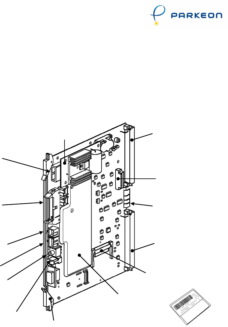
2.1 Main board
Socket A of rack's
ribbon cable (for card
reader and relay board)
Earthing pins
Socket B of rack's
ribbon cable
Main board
protective cover
On/off switch
Battery socket
Power sockets for
peripherals
Power socket
50-pin socket for
display unit and
keypad ribbon cable
D4849
Datapack connector
D4628
Centralisation
connector
Loader card connected
to 20-pin socket
Extraction lever
Loader socket
WIFI kit - Neops base terminals - Operation manual
6
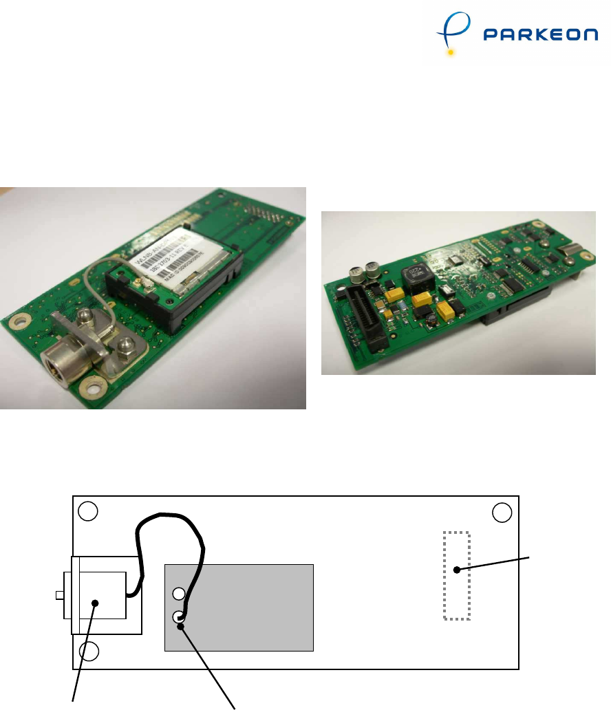
2.2 Slave board
The slave board is connected directly to the main board centralisation connector.
Slave board + modem (top view) Slave board (bottom view)
D5336
D5335
Antenna
Connector
Antenna connector
Centralisation
connector
(for main
board)
Slave
board
Wifi Modem
Antenna
Adaptator
WIFI kit - Neops base terminals - Operation manual
7
2.3 Description of functions
2.3.1 Installation and initialisation
The slave board and modem are mounted on the main board.
Make sure the antenna is properly.
Function 80: modem initialisation.
To initialise the modem, use on-site programming function 80 described below:
1.
MODEM PRESENT
YES: 1 NO: 2
Enter 1 to start initialising the modem.
Modem initialisation:
From that point on, the main board initialises the modem without any more user
input. The main board displays progress of the initialisation stage:
2.
PLEASE
WAIT
During this stage, the main board powers up the modem.
3.
MODEM
INITIALISATION
During this stage, the modem sends initialisation.
If the initialisation procedure fails at this point (message “Init. not completed”),
that means the slave board is not answering the main board.
If the procedure is completed correctly, the main board moves on to the next
stage.
WIFI kit - Neops base terminals - Operation manual
8
4.
NETWORK
REGISTRATION
During this stage, the main board waits for the modem to register on the Wifi
network.
1. If initialisation fails during this stage (message “Init. not completed”), that
means that the modem cannot be registered on the Wifi network : check
that the antenna is correctly connected to the modem and that the
antenna cable is correctly screwed to the antenna adapter.
5.
INITIALISATION
COMPLETED
When the main board displays this message, that means that the modem has been
successfully initialised. Initialisation is used to:
• check assembly in the terminal;
• check that the modem is capable of registering with the network.
That is why function 80 should be repeated every time, whenever:
• a new kit is installed;
• the kit is removed from then put back into the terminal;
Once the modem has been initialised, it still needs initialising on the terminal:
• call numbers: server-side IP address (function 44);
• configuring whether or not alarms are sent to the server (function 42).

WIFI kit - Neops base terminals - Operation manual
9
Programming Parkfolio
Neo
On-Line numbers (function 44)
This function is used to save the Parkfolio
Neo
On-Line numbers in the memory of
the main board.
Numbers 1 to 10 are the server's IP address for Wifi.
2.3.2 Wifi communication
To make a Wifi call, just use function 44 to programme the IP address of the
Parkfolio
Neo
On-Line.
In order to make a GPRS call, the terminal needs to know the server’s UDP Port
number : this is the number of the port used to communicate with Parkfolio
Neo
On-
Line. The port number entered while setting up Parkfolio
Neo
On-Line for Wifi
communication is to be used here.
Function 40: communication test
Function 40 is used to test communication between the terminal and the
communication server irrespective of the communication medium (Mobitex, GSM,
SMS, GPRS and Wifi).
1. If a GSM Data number is programmed, the main board will try and make a
GSM Data call with Parkfolio
Neo
On-Line. If the call succeeds and
communication with Parkfolio
Neo
On-Line is satisfactory, the main board
displays the message "Communication test OK".
2. If the programmed number is the IP address, the terminal tries to
communicate via Wifi with Parkfolio
Neo
On-Line:
o If the communication is satisfactory, the main board displays
"Communication OK";
• If the main board displays “Transmission problem”, there may be several
reasons for such behaviour:
1. The IP address of the server is incorrect;
2. Parkfolio
Neo
On-Line is not receiving data from the terminal (incorrect
firewall setup, incorrect router setup etc.);
3. Parkfolio
Neo
On-Line is not responding (the Parkfolio
Neo
On-Line service
is down).
WIFI kit - Neops base terminals - Operation manual
10
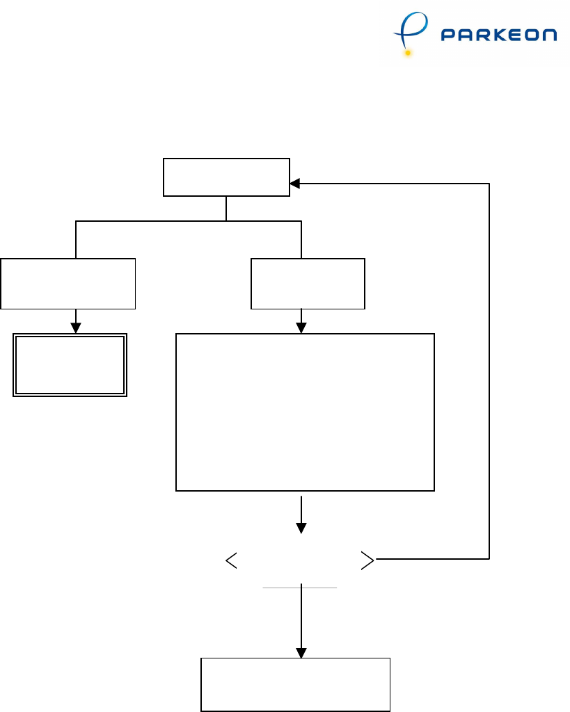
Below is a flowchart showing what action should be taken if there is a problem with
function 40 during Wifi configuration:
Function 40
Transmission
problem
Check the UDP port number in GPRS
Setup of the Parkfolio
Neo
On-
Line for
this SIM
Check the firewall and router setup.
Check that Parkfolio
Neo
On-Line is
operating, using the display interface
NO
Error detected
and corrected?
(F40)
YES
Contact product support
Communication
OK
WIFI
Centralisation
system OK