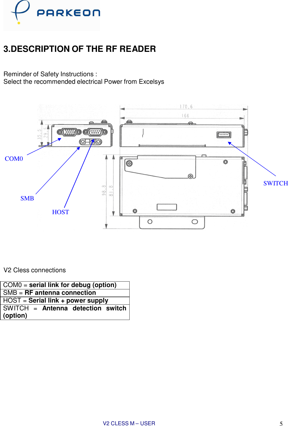
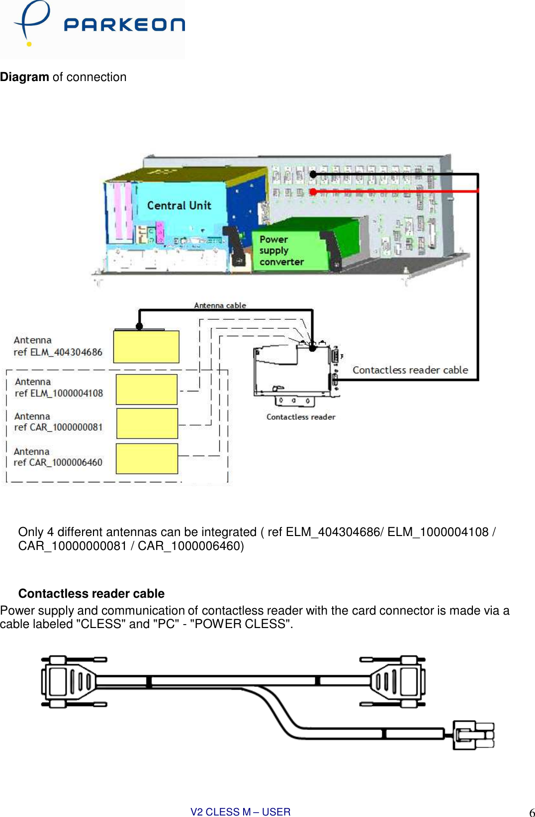
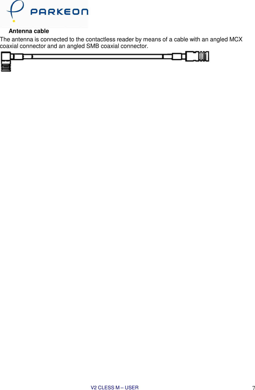
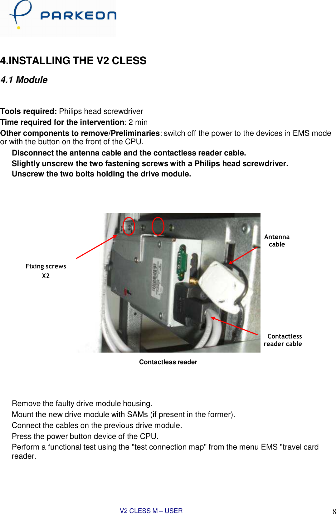
PARKEON V2-CLESS-M RFID Reader User Manual T2X V2 CLESS EN

PARKEON RFID Reader T2X V2 CLESS EN

USERS MANUAL

V2 CLESS M – USER MANUAL 1                           V2 CLESS M   User Manual
V2 CLESS M – USER MANUAL 2     FOREWORD   INSTALLATION. We recommend you to read these instructions very carefully. They are included with your V2 Cless Reader in order to explain its installation.  USE. Once it is installed and equipped with the application you case use your V2 Cless reader.  GUARANTEE AND SAFETY. In order to benefit from the guarantee on this equipment  and in order to follow the safety instructions, only authorized person shall entrust assembly or disassembly procedures and installed the reader.       CONTENTS  1. SAFETY INSTRUCTIONS .......................................................................................................................................... 3 2. UNPACKING. PRODUCT CONTENTS...................................................................................................................... 4 3. DESCRIPTION OF THE RF READER ....................................................................................................................... 5 4. INSTALLING THE V2 CLESS .................................................................................................................................... 7 4.1 Module .................................................................................................................................................................. 7 4.2 Antenna................................................................................................................................................................. 8 5. INSTALLING AND REMOVING SECURITY ACCESS MODULES........................................................................... 9 6. DAILY  USE .............................................................................................................................................................. 10 7. V2 CLESS CHARACTERISTICS ............................................................................................................................. 11 8. EC STANDARD COMPLIANCE MARKING ............................................................................................................ 12 9. FCC COMPLIANCE STATEMENT........................................................................................................................... 12
V2 CLESS M – USER MANUAL 3     1.SAFETY INSTRUCTIONS       A-  In order to power down your V2 CLess :  Disconnect the V2 Cless power supply block from the electric power supply network  B- Electrical power supply  a.  Only use Parkeon Contacless reader cable b.  Only use Parkeon antenna cable with it’s Ferrite for EMI protection c.   The V2 Cless input voltage should be +12VDC +/- 10%    C- Reader cover Flap  The cover flap located on the side ( see chapter – installation and removal of Sams) must be in place during normal operation
V2 CLESS M – USER MANUAL 4    2.UNPACKING. PRODUCT CONTENTS    Carefully preserve the packaging of the V2 Cless and the antenna. It must be re-used whenever the reader is shipped.
V2 CLESS M – USER MANUAL 5     3.DESCRIPTION OF THE RF READER    Reminder of Safety Instructions : Select the recommended electrical Power from Excelsys              COM0    SWITCH  SMB  HOST          V2 Cless connections  COM0 = serial link for debug (option) SMB = RF antenna connection HOST = Serial link + power supply SWITCH  =  Antenna  detection  switch (option)
V2 CLESS M – USER MANUAL 6    Diagram of connection        cess      Only 4 different antennas can be integrated ( ref ELM_404304686/ ELM_1000004108 / CAR_10000000081 / CAR_1000006460)   Contactless reader cable Power supply and communication of contactless reader with the card connector is made via a cable labeled "CLESS" and "PC" - "POWER CLESS".
V2 CLESS M – USER MANUAL 7   Antenna cable The antenna is connected to the contactless reader by means of a cable with an angled MCX coaxial connector and an angled SMB coaxial connector.
V2 CLESS M – USER MANUAL 8      4.INSTALLING THE V2 CLESS  4.1 Module    Tools required: Philips head screwdriver Time required for the intervention: 2 min Other components to remove/Preliminaries: switch off the power to the devices in EMS mode or with the button on the front of the CPU. Disconnect the antenna cable and the contactless reader cable. Slightly unscrew the two fastening screws with a Philips head screwdriver. Unscrew the two bolts holding the drive module.         Antenna cable   Fixing screws X2         Contactless reader cable  Contactless reader      Remove the faulty drive module housing. Mount the new drive module with SAMs (if present in the former). Connect the cables on the previous drive module. Press the power button device of the CPU. Perform a functional test using the "test connection map" from the menu EMS "travel card reader.
V2 CLESS M – USER MANUAL 9      4.2 Antenna   Connect the antenna cable. Put it on the four screws.
V2 CLESS M – USER MANUAL 10       5.INSTALLING AND REMOVING SECURITY ACCESS MODULES   Tools required: key 8 Time required for the intervention: 8 + 3 min   Unscrew the screw that locks the access trap SAMs. Rotate the trap to access locations of SAMs.   Locking Screw  SAMs slot            Contactless reader Access trap SAMs  Remove the SAMs their modules. Set new in empty slot positions. Replace the contactless reader. Connect the cables on the previous contactless reader. Press the power button device of the CPU. Perform a functional test using the "test connection map" from the menu EMS "travel card reader.
V2 CLESS – USER MANUAL 1010     6. DAILY  USE    No specific care shall be done. Clean the antenna each year with Isopropanol
V2 CLESS – USER MANUAL 1111     7. V2 CLESS CHARACTERISTICS    Physical Characteristics Mass                                  : approximately 400g without cable Dimensions                       : approximately 166x79x35 mm (LxWxH)  Standards See “EC standard compliance marking” in appendix  Operating conditions Class II equipement  Electric supply network      : 12VDC +/- 10% Max. consumption             : 0.5 A  Ambiant temperature         : from -25°C to +70°C Max. relative humidity        : 95% at +55°C  Serial link                           : COM, level RS232  Storage conditions Storage temperature         : -20°C, +85°C Max relative humidity         : 90% at +55°C
V2 CLESS – USER MANUAL 1212    8. EC STANDARD COMPLIANCE MARKING    EC standard compliance marking certifies that the product stipulated below:  Complies with the basic requirements of European Directive 1999/5/CE of 09/03/1999, known as the “R&TTE Directive” concerning RF equipment and telecommunications terminals with respect to :      Health and safety protection of the user and all other persons,     EMC protection  Conforms to the following harmonized standards:      CEI  60950-1         Electrical safety of data processing equipment including electrical office equipment. Issue CEI 60950-1: 2005/A1:2010      RSS-Gen              Issue 3, December 2010 General  Requirements and  information for  the   certification of  Radio Apparatus     RSS-210              Issue 8, December 2010 Licence-exempt Radio Apparatus (All Frequency Bands) : Category I equipment    ANSI        C63.4 (03)  Methods of measurement of Radio-Noise Emissions from low-voltage Electrical and Electronic Equipment in the Range of 9 KHz to 40 GHz    9. FCC COMPLIANCE STATEMENT   This device complies with part 15 of the FCC rules. Operation is subject to the following two conditions: (1). This device may not cause harmful interference, and (2) this device must accept any interference received, including interference that may cause undesired operation.  This equipment has been tested and found to comply with the limts for a class B digital device, pursuant to part 15 of the FCC Rules.
V2 CLESS – USER MANUAL 1313          © Copyright 2010 Parkeon. All rights reserved. Parkeon reserves all proprietary rights relating to the contents of this document.Parkeon Reserves all rights over usage, reproduction, representation, marketing, translation, adaptation Or modification, and generally all rights over present and future utilisation by any means, for any Purpose and in any territory, throughout the period of protection. All use of the contents of this Document requires the prior written permission of Parkeon. Parkeon reserves the right to change data, drawings and descriptions without prior notice. Certain characteristics may vary according to customer requirements and do not represent a commitment by Parkeon.  Parkeon UK Ltd. Membrain House Ferndown Industrial Estate Wimborne, Dorset BH21 7PP – United Kingdown Phone +44 1202 850927 - Fax +44 1202 850903  Parkeon Inc. 40 Twosome Drive, Unit 7 Moorestown NJ 08057 – USA Phone +1 856 234 8000 - Fax +1 856 234 7178  Parkeon S.A.S Parc La Fayette, 6 rue Isaac Newton, 25075 Besançon Cedex 9 - France Phone +33 (0)3 81 54 56 00 – Fax +33 (0)3 81 54 49 96 Head office 100 avenue de Suffren, 75015 Paris - France Parkeon S.A.S au capital de 30.382.146 euros 444 719 272 R.C.S Paris

Navigation menu