PARROT CK5050PIA Bluetooth module, hands free car kit User Manual CK5050 Datasheet 1 03
PARROT Bluetooth module, hands free car kit CK5050 Datasheet 1 03
PARROT >
Users Manual
1 (28)
Created by : Reference Title
David COROLLEUR
DC-2008-029 Hands Free Car Kit Module CK5050+ - Datasheet
Revised by : Date edition N° :
David COROLLEUR
09/09/2008 1.03
Approved by : Date Function
Hands Free Car Kit Module
CK5050+
Datasheet
Product Scope
Parrot has identified a demand for the integration of the telephony into a host product like car radio or
navigation system. The answer to this demand is CK5050+.
The CK5050+ is a feature-rich Bluetooth Hands Free Car Kit solution dedicated for the integration of
Handsfree Bluetooth applications in car radios and car telematics systems.

2 (28)
Created by : Reference Title
David COROLLEUR
DC-2008-029 Hands Free Car Kit Module CK5050+ - Datasheet
Revised by : Date edition N° :
David COROLLEUR
09/09/2008 1.03
Approved by : Date Function
1
PRODUCT OVERVIEW 3
1.1
CK5050+ Features 3
1.2
Memory Flash required 4
2
ELECTRICAL ARCHITECTURE 5
2.1
CK5050+ internal Block Diagram 5
2.2
Electrical Interfaces Characteristics 6
2.3
Main Connector Pinout 8
3
HARDWARE LAYOUT 10
3.1
Components placement with internal antenna (PI040123AA) 10
3.2
Components placement without internal antenna (PI040114AA - PI040124AA) 12
4
SOFTWARE SPECIFICATIONS 14
4.1
Bluetooth Stack 14
4.2
Bluetooth Profiles Supported 14
4.3
Software Architecture 14
4.4
Software Interface 15
5
MECHANICAL DESIGN 16
5.1.1
Shielding 16
5.1.2
CK5050+ versions 18
5.1.3
Integration on the motherboard 19
5.1.4
CK5050+ mechanical design 20
6
DEVELOPMENT TOOLS 23
7
FCC REQUIREMENTS FOR MODULE APPLICATION 25
8
CE DECLARATION 27
9
ANNEXE 1: CK5050+APPLICATION (EXAMPLE) 28
3 (28)
Created by : Reference Title
David COROLLEUR
DC-2008-029 Hands Free Car Kit Module CK5050+ - Datasheet
Revised by : Date edition N° :
David COROLLEUR
09/09/2008 1.03
Approved by : Date Function
1 Product Overview
This document is the Datasheet of the Parrot CK5050+ Bluetooth Module.
The CK5050+ is a feature-rich Bluetooth platform dedicated for the integration of Bluetooth applications in car
audios, car telematic systems or any systems requiring a complete embedded Bluetooth solution.
1.1 CK5050+ Features
Bluetooth connectivity
•
Bluetooth Power Class 2 Radio
•
Embedded Bluetooth v1.1, v1.2 & v2.0 compliant
•
Embedded profiles
•
Compatible with all Bluetooth phones
•
Pairing and connection with all Bluetooth Devices: Phones, Smartphones, PDA …
•
Multiple user support: Up to 5 paired phones
•
Multiple connection (up to 3 device connected at the same time)
•
Multiple profile (for example A2DP and HFP at the same time with same or different devices)
Phone
•
Pick-up, Hang-up, Redial
•
Automatic answer (from host via dial command)
•
Send DTMF during calls
•
Private Mode
Phone Book
•
Automatic Phone book synchronization over Bluetooth (up to 1000 names)
•
Call history (dialed number, received calls, missed calls)
•
All Synchronization Methods
•
Full Unicode for compatibility with numerous characters sets (European, Russian, Chinese, Japanese…)
Digital Signal Processing and Acoustics
•
Acoustic Echo cancellation for Full Duplex operation
•
Noise reduction
•
Beam forming with 2 microphones inputs
•
Volume control
•
Speaker dependant voice recognition (trained names and keyword)
•
Speaker independent voice recognition (Nuance licensing)
•
Text To Speech feature.
Audio Streaming
•
Embedded SBC decoder
•
Embedded MP3 decoder from Thomson Licensing (optional)
•
Stereo audio output
Miscellaneous
•
Provide Phone Battery Level and Network Level, Carrier Name (depends on phones)
•
Embedded test pattern
Software Update
•
Full standard Software available (free upgrade from Parrot homepage)
•
Software update available through Bluetooth or UART
•
Very large compatibility with Phones, Smartphones, PDAs, Music players
USB
•
USB 2.0 Full Speed
•
Access to mass storage device
•
File browsing
4 (28)
Created by : Reference Title
David COROLLEUR
DC-2008-029 Hands Free Car Kit Module CK5050+ - Datasheet
Revised by : Date edition N° :
David COROLLEUR
09/09/2008 1.03
Approved by : Date Function
1.2 Memory Flash required
•
Flash required for the CODE: Around 2Mbytes
•
Flash required for the user Data (settings, phonebook…) : Around 4 MBytes
•
Flash required for speaker independent voice recognition and text to speech:
Voice recognition only: 3 Mbytes + 1.1 Mbytes per language
Voice recognition and Text To Speech: 7 Mbytes + 16 Mbytes per language
Example for 1 language:
Code Data Required Memory Flash
VR + TTS 23 MBytes 2 MBytes 4 MBytes
29 MBytes 256 MBits
VR only 4.1 MBytes 2 MBytes 4 MBytes
10.1 MBytes
128 Mbits
Example for 6 languages:
Code Data Required Memory Flash
VR + TTS 103 MBytes 2 MBytes 4 MBytes
109 MBytes 1 GBits
VR only 9,6 MBytes 2 MBytes 4 MBytes
15.6 MBytes
128/256 Mbits
5 (28)
Created by : Reference Title
David COROLLEUR
DC-2008-029 Hands Free Car Kit Module CK5050+ - Datasheet
Revised by : Date edition N° :
David COROLLEUR
09/09/2008 1.03
Approved by : Date Function
2 Electrical Architecture
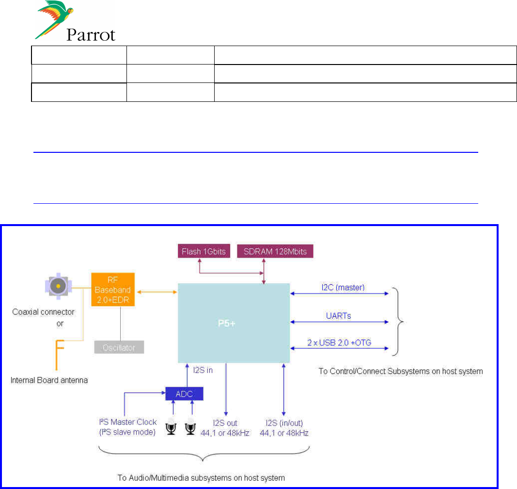
2.1 CK5050+ internal Block Diagram
CK5050+ Simplified Block Diagram
The main electrical interfaces provided by the CK5050+ are:
• Bluetooth: 2.0 EDR
• Audio:
Digital I2S interface: 1 stereo input + 2 stereo output (need to have an I2S codec on the motherboard)
Analog interface: 2 audio inputs
• Serial Link : UART for the software interface through AT commands
• 2 x USB 2.0 OTG
• I²C Interface
• 3.3 V Power Supply
• Flash : 256Mbits / 512Mbits / 1Gbits
• SDRAM: 64Mbits/ 128Mbits
6 (28)
Created by : Reference Title
David COROLLEUR
DC-2008-029 Hands Free Car Kit Module CK5050+ - Datasheet
Revised by : Date edition N° :
David COROLLEUR
09/09/2008 1.03
Approved by : Date Function
2.2 Electrical Interfaces Characteristics
Absolute Maximum Rating
Min
Max
Unit
Supply
Voltage
-
0.3
3.8
V
Storage
Temperature
-
40
+125
°C
Operating Conditions
Min
Max
Unit
Supply
Voltage
3,2
3.6
V
Ambiant
Temperature
-
40
+85
°C
UART: 16C550 Compatible Type. A bit “Start Bit=0” is added to the beginning of each word (8bits). The Least
Significant Bit (LSB) is sent first. A “Stop Bit=1” is sent by the transmitter at the end of each word.
MaxVOL=0.15V
MinVOH=Vcc-0v15 (at IOH=0.1mA) open collector with build in 2.5k pull up
MaxVIL=0.8V
MinVIH=2V
UART0_TX & UART1_TX:
Min
Max
Condition
Trise (ns)
10
Cload = 50pF
Tfall (ns)
10
Cload = 50pF
The UART1_RX and UART0_RX are Schmitt trigger inputs
I2C
MaxVOL=0.15V
MinVOH=Vcc-0v15
MaxVIL=0.8V
MinVIH=2V
RESET: Asynchronous reset signal, used to reset the Parrot Daughter Board, active low.
MaxVIL=0.4V
MinVIH=2.5V
MIC_PWR: Connect to electret condenser microphone (Impedance less than 2.2kOhms)
Electrical characteristics of microphone:
Operating voltage: 2..02V-2.48V DC
Current consumption: 500µA max.
Use of pre-amplified microphones is in option.
Optional: another power supply (from motherboard) can be used to supply the microphone(s)
VCC: Supply voltage 3.4V(-0.2V/+0.2V) including tolerances, thermal changes, noise over/under shoot due to
load change and/or car battery voltage change, load dump.
Mean current : <300 mA (All components active and communication or streaming mode)
Peak current < 1.5A during switch on: > mA during 700 ms (max).
7 (28)
Created by : Reference Title
David COROLLEUR
DC-2008-029 Hands Free Car Kit Module CK5050+ - Datasheet
Revised by : Date edition N° :
David COROLLEUR
09/09/2008 1.03
Approved by : Date Function
P
OWER
C
ONSUMPTION
F
UNCTIONING MODES
C
URRENT ON
3.4V
R
EMARKS
STOP MODE
<20 µA BT radio and Parrot5+ ASIC stopped, Internal voltage regulator
switched off.(Power off or Reset active)
STANDBY MODE
<200 mA BT module in sniff mode, Parrot ASIC in idle
HANDSFREE MODE
<300 mA Hands free communication with a Bluetooth enabled phone
AUDIO STREAMING
<300 mA Reception of an encoded stream, decoding, playing of the audio
8 (28)
Created by : Reference Title
David COROLLEUR
DC-2008-029 Hands Free Car Kit Module CK5050+ - Datasheet
Revised by : Date edition N° :
David COROLLEUR
09/09/2008 1.03
Approved by : Date Function
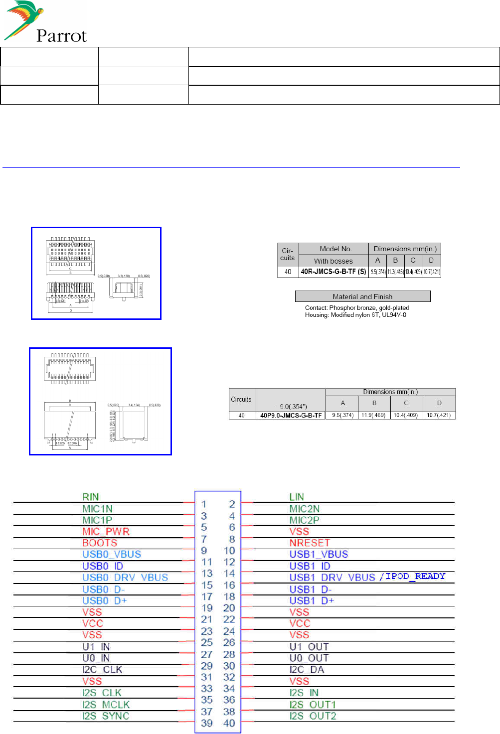
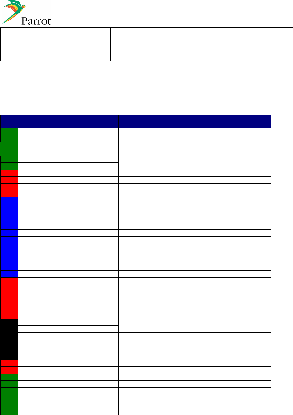
2.3 Main Connector Pinout
Main connectors:
Male connector:
Female connector:
The following pinout allows an interface to the CK5050+ according to market standards:
The following pinout allows an interface to the CK5050+ according to market standards:
9 (28)
Created by : Reference Title
David COROLLEUR
DC-2008-029 Hands Free Car Kit Module CK5050+ - Datasheet
Revised by : Date edition N° :
David COROLLEUR
09/09/2008 1.03
Approved by : Date Function
PIN
FUNCTION
INPUT
/ OUTPUT
COMMENT
1
RIN
I
Line in : right input
2
LIN
I
Line in : left input
3 MIC1N I
Microphones : Analog audio inputs
4
MIC2N
I
5
MIC1P
I
6
MIC2P
I
7
MIC_PWR
O
Microphone power supply
8
V
SS
I
Ground
9
BOOTS
I
To update the
soft
10
NRESET
I
RESET trigger Input
11 USB0_VBUS I
USB0 Vbus 5V
12
USB1_VBUS
I
USB1 Vbus 5V
13
USB0_ID
I
USB0
ID pin of mini AB receptacle
(OTG)
14
USB1_ID
I
USB1
ID pin of mini AB receptacle
(OTG)
15
USB0_DRV_VBUS
O
Drive VBUS (OTG) USB0
16
USB1
_DRV_VBUS /
IPOD_READY O/I
Drive VBUS (OTG) USB1 / Connected to
IPOD_Authentication_Coprocessor
17
USB0_D
-
O/
I
USB0 interface D
-
signal
18
USB1_D
-
O/I
USB1 interface D
-
signal
19
USB0_D+
O
/I
USB0 interface D+
signal
20
USB1_D+
O/
I
USB1 interface D+
sig
nal
21
VSS
I
Ground
22
VSS
I
Ground
23
VCC
I
POWER 3.
4
V
24
VCC
I
POWER 3.
4
V
25
VSS
I
Ground
26
VSS
I
Ground
27
U1_IN
I
16C550 Compatible type
(for Debug interface)
28
U1_OUT
O
29
U0_IN
I
16C550 Compatible type
(for Host AT commands and Flash Update interface)
30
U0_OUT
O
31
I2C_CLK
O
I2C
clock
32
I2C_DA
O/I
I2C data
33
VSS
I
Ground
34
VSS
I
Ground
35
I2S_CLK
O/I
I2S serial clock
36
I2S_IN
I
I2S serial data in 1
37
I2S_MCLK
O/I
I2S Master clock
38
I2S_OUT1
O
I2S serial data out
39
I2S_SY
NC
O/I
I2S
synchronization
40
I2S_OUT2
O
I2S serial data out (secondary)
10 (28)
Created by : Reference Title
David COROLLEUR
DC-2008-029 Hands Free Car Kit Module CK5050+ - Datasheet
Revised by : Date edition N° :
David COROLLEUR
09/09/2008 1.03
Approved by : Date Function
3 Hardware layout
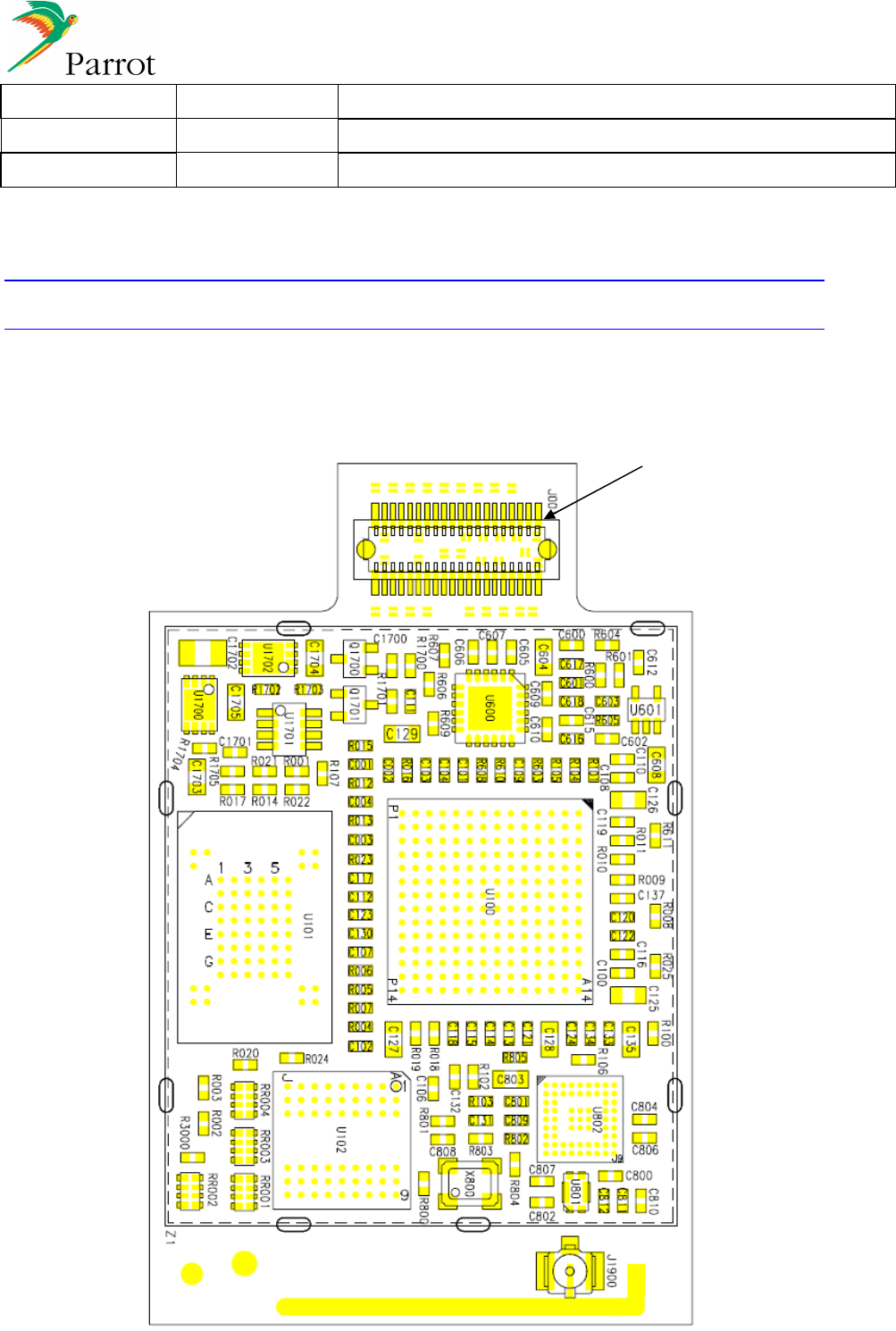
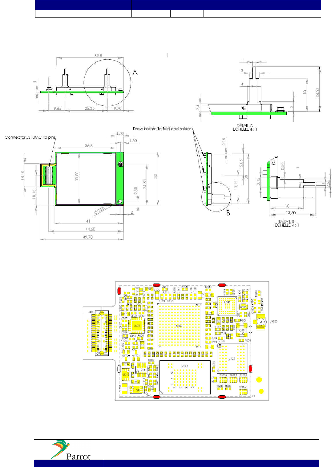
3.1 Components placement with internal antenna (PI040123AA)
Details:
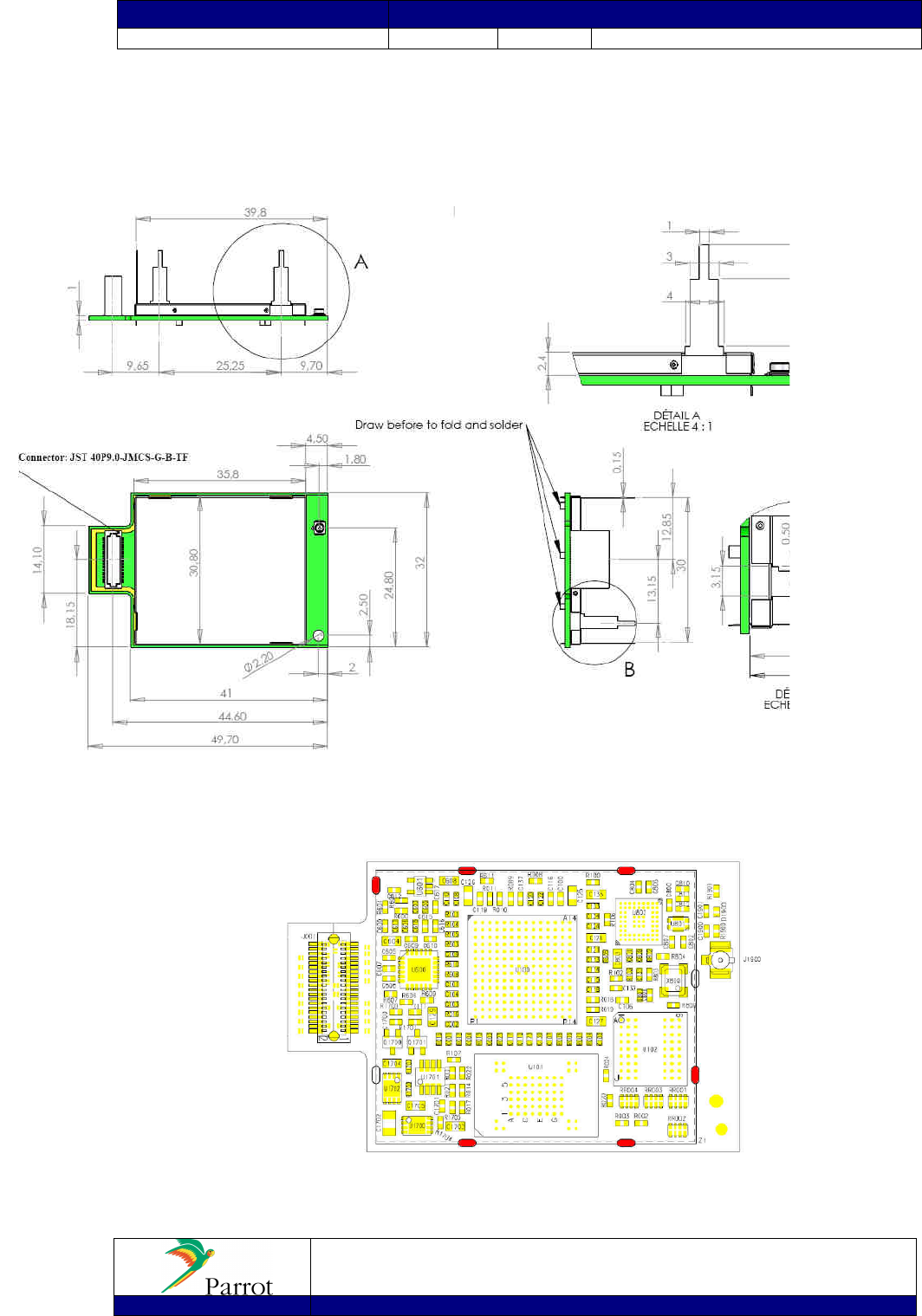
U100: Parrot5+ ASIC (BGA) + U101/U102: SDRam/Flash (BGA) + U802 BT radio transceiver (BGA) + U1702:
1V8 Voltage regulator (DFN8) + U1700: 1V2 Voltage regulator (DFN8) + U1701: Voltage supervisor (TSOT8)
+U600: ADC (QFN) +X800: Precision crystal oscillator + J001: Main connector
COMPONENTS SIDE
1
11 (28)
Created by : Reference Title
David COROLLEUR
DC-2008-029 Hands Free Car Kit Module CK5050+ - Datasheet
Revised by : Date edition N° :
David COROLLEUR
09/09/2008 1.03
Approved by : Date Function
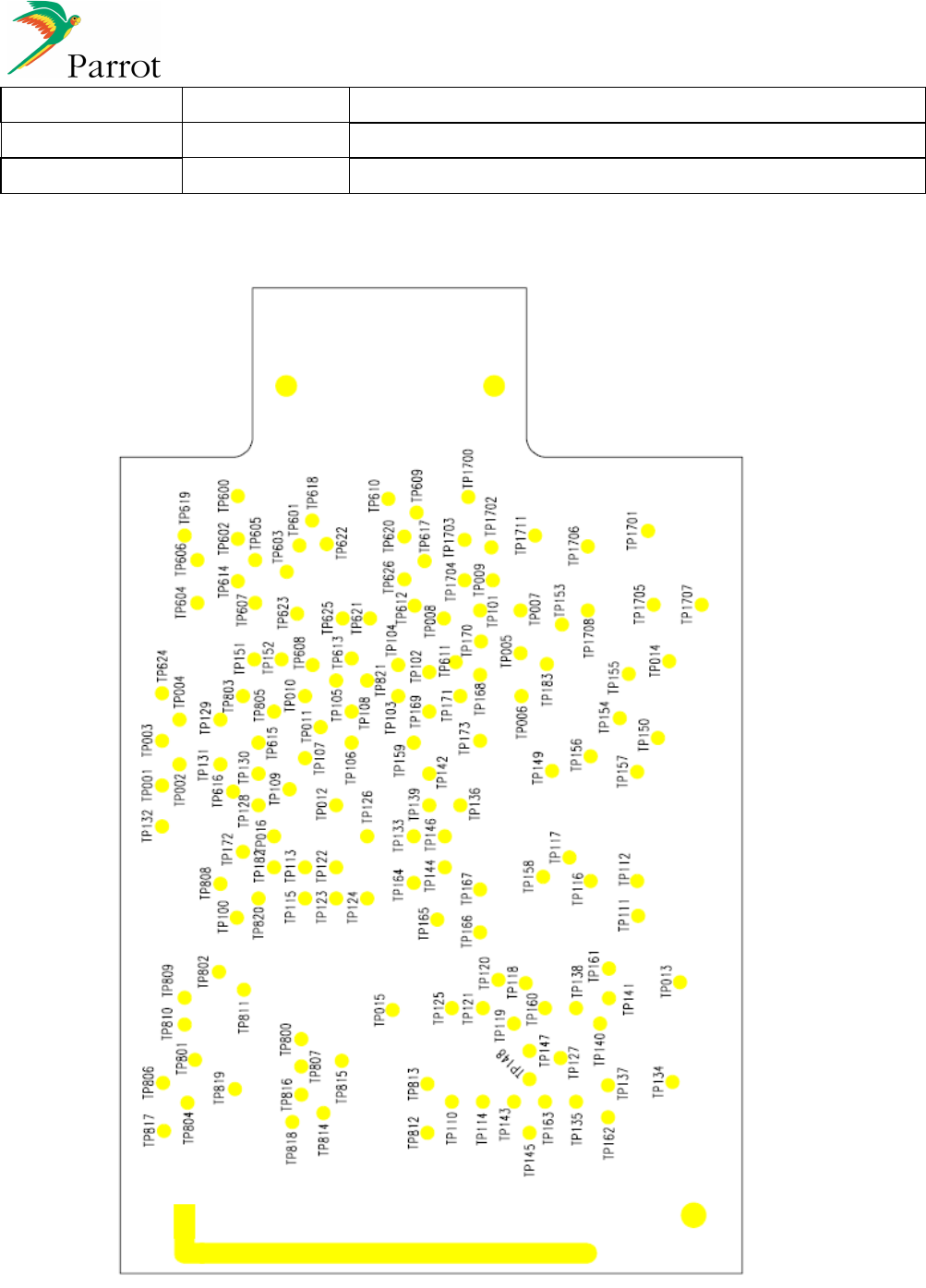
BOTTOM SIDE
PCB size: 32mm x 50.7mm Tolerances +/- 0.1 mm
12 (28)
Created by : Reference Title
David COROLLEUR
DC-2008-029 Hands Free Car Kit Module CK5050+ - Datasheet
Revised by : Date edition N° :
David COROLLEUR
09/09/2008 1.03
Approved by : Date Function
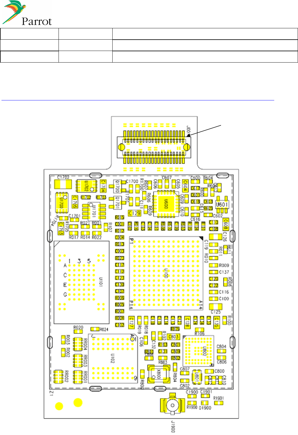
3.2 Components placement without internal antenna (PI040114AA - PI040124AA)
COMPONENTS SIDE
1
13 (28)
Created by : Reference Title
David COROLLEUR
DC-2008-029 Hands Free Car Kit Module CK5050+ - Datasheet
Revised by : Date edition N° :
David COROLLEUR
09/09/2008 1.03
Approved by : Date Function
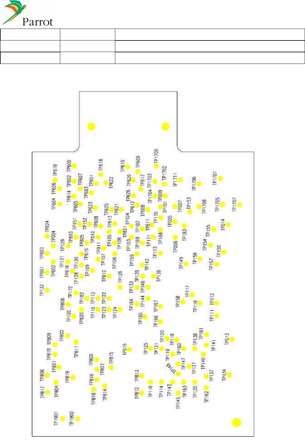
BOTTOM SIDE
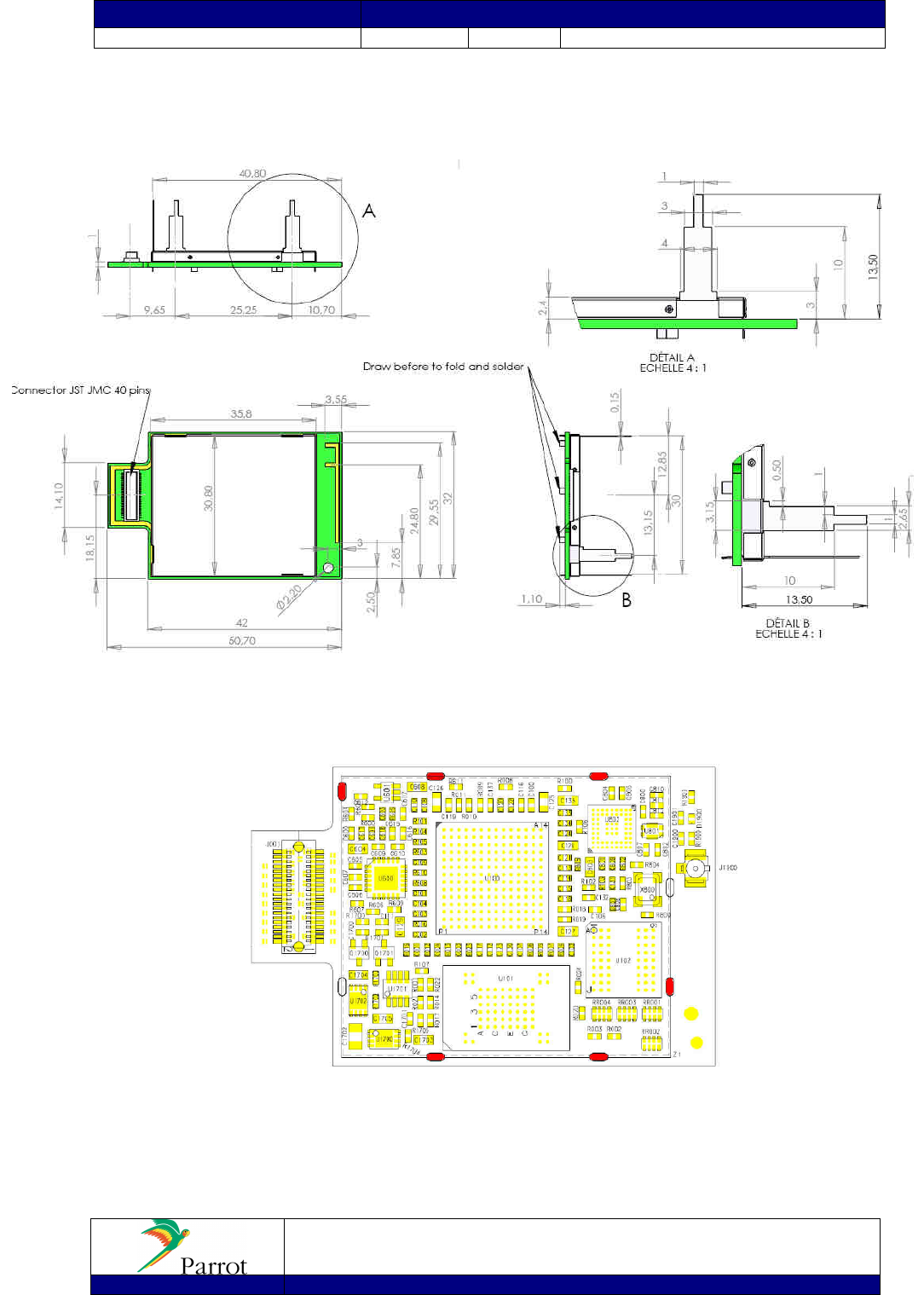
PCB size: 32mm x 49.7mm Tolerances +/- 0.1 mm
14 (28)
Created by : Reference Title
David COROLLEUR
DC-2008-029 Hands Free Car Kit Module CK5050+ - Datasheet
Revised by : Date edition N° :
David COROLLEUR
09/09/2008 1.03
Approved by : Date Function
4 Software Specifications
4.1 Bluetooth Stack
HCI (Host Controller interface),
L2CAP (Logical Link Control and Adaptation Protocol),
RFCOMM (TS011...),
SDP (Service Discovery Protocol),
OBEX (IrDA Object Exchange).
4.2 Bluetooth Profiles Supported
Generic Access Profile
GAP
Phone Management
•
HFP 0.96 - 1.0 - 1.5
•
HSP 1.0
Message Management
•
MAP 1.0
Phone Book
•
PBAP 1.0
•
SYNC 1.1 (IrMC SYNC over BT)
•
SYNCML
•
OPP 1.0 Server/Client (Vcard 2.1)
•
GSM 07.07 AT Commands
•
Nokia synchronization protocol
Multimedia
•
A2DP (Audio)
•
SBC decoding
•
(optional MP3 decoding)
•
AVDTP
•
AVRCP
Others
•
SPP 1.1
•
BNEP, PAN
•
FTP 1.0
•
Image transfer over OPP
•
DUNP 1.1
•
Software update over SPP
•
Remote configuration
4.3 Software Architecture
See Bluetooth Stack Software Specification (Confidential).
15 (28)
Created by : Reference Title
David COROLLEUR
DC-2008-029 Hands Free Car Kit Module CK5050+ - Datasheet
Revised by : Date edition N° :
David COROLLEUR
09/09/2008 1.03
Approved by : Date Function
4.4 Software Interface
The main target of the software interface is to provide a high level command set, hiding the internal complexity of
the Bluetooth function and the variability of its standard across different devices.
This software interface is based on well-known AT commands. Some of these commands are directly derived from
the GSM 07.07 recommendation and from the appropriate Bluetooth profiles.
Some supplementary commands are used to manage Bluetooth related functions like device pairing and connection
management as well as the acoustic and speech recognition functions.
AT Command List and Bluetooth AT Command Software Specification is available.
BLUES supports Unicode, which allows the management of accents and phonebook in any language.
BLUES is also very friendly with a flexible MMI. One can use BLUES with a simple single or double key interface as
well as a diversity of graphic displays.
16 (28)
Created by : Reference Title
David COROLLEUR
DC-2008-029 Hands Free Car Kit Module CK5050+ - Datasheet
Revised by : Date edition N° :
David COROLLEUR
09/09/2008 1.03
Approved by : Date Function
5 Mechanical Design
The CK5050+ features a male connector allowing a connection to the motherboard through a female connector.
Board to Board Main Connector
40 PIN connector
0.5mm pitch double row
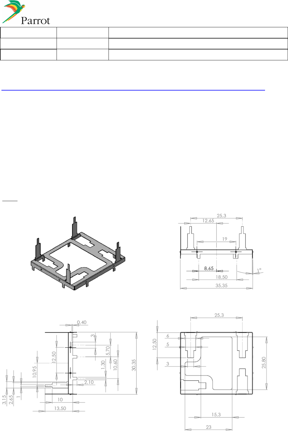
5.1.1 Shielding
S
HIELDING
P
ART
1
17 (28)
Created by : Reference Title
David COROLLEUR
DC-2008-029 Hands Free Car Kit Module CK5050+ - Datasheet
Revised by : Date edition N° :
David COROLLEUR
09/09/2008 1.03
Approved by : Date Function
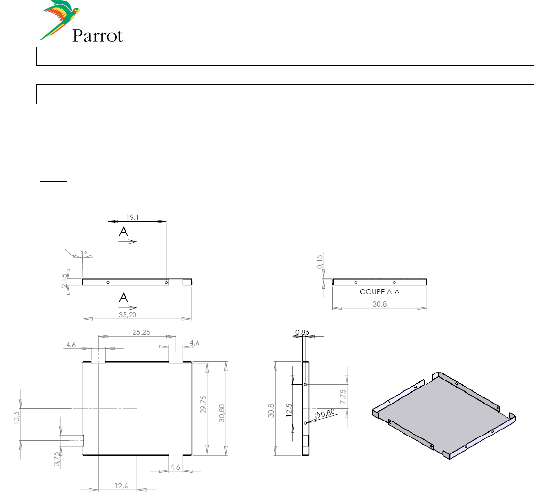
P
ART
2
18 (28)
Created by : Reference Title
David COROLLEUR
DC-2008-029 Hands Free Car Kit Module CK5050+ - Datasheet
Revised by : Date edition N° :
David COROLLEUR
09/09/2008 1.03
Approved by : Date Function
5.1.2 CK5050+ versions
CK5050+ VERSIONS
PI Number Connector type
Bluetooth Antenna
Model
PI040114 Female (9 mm) External CK5050+FEA
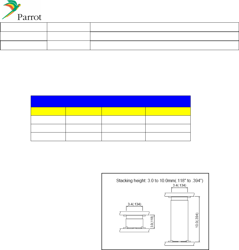
PI040123 Male Internal CK5050+MIA
PI040124 Male External CK5050+MEA
CK5050+
WITH
M
ALE
C
ONNECTOR
•
CK5050+
40R-JMCS-G-TF from JST
•
Host
40P3.0-JMCS-G-TF
Or
40P10.0-JMCS-G-TF
CK5050+
WITH
F
EMALE
C
ONNECTOR
•
CK5050+
40P9.0-JMCS-G-B-TF from JST
•
Host
40RF-JMCS-G-1-TF from JST (Absorption misalignment type)
19 (28)
Created by : Reference Title
David COROLLEUR
DC-2008-029 Hands Free Car Kit Module CK5050+ - Datasheet
Revised by : Date edition N° :
David COROLLEUR
09/09/2008 1.03
Approved by : Date Function
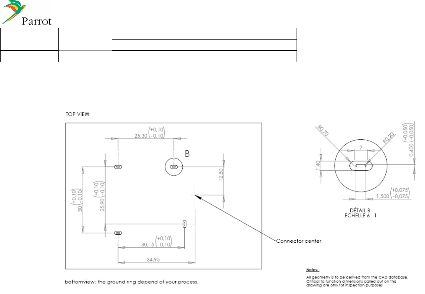
5.1.3 Integration on the motherboard
Prepared
David COROLLEUR
Title
CK5050
+
Datasheet
Approved
Hocine BELKHOUDJA
Date
1
5
/04
/08
Revision
1.01
File
CK5050
+_Datasheet_1.03.doc
PROPRIETARY AND CONFIDENTIAL
The information contained in this document is the sole property of Parrot.
Any reproduction in part or as a whole without the written permission of Parrot is prohibited.
Project
CK5050+
Part Numbers
20
20
5.1.4 CK5050+ mechanical design
CK5050+
WITH
E
XTERNAL
A
NTENNA
(PI040114AA)
Mechanical dimensions (Tolerances: -0.1/0.1 mm for the thickness and -0.2/0.2 mm for length and the
width) with external BT antenna
The holes highlighted in are the holes where the shielding is soldered
Prepared
David COROLLEUR
Title
CK5050
+
Datasheet
Approved
Hocine BELKHOUDJA
Date
1
5
/04
/08
Revision
1.01
File
CK5050
+_Datasheet_1.03.doc
PROPRIETARY AND CONFIDENTIAL
The information contained in this document is the sole property of Parrot.
Any reproduction in part or as a whole without the written permission of Parrot is prohibited.
Project
CK5050+
Part Numbers
21
21
CK5050+
WITH
PCB
A
NTENNA
(PI040123AA)
Mechanical dimensions (Tolerances: -0.1/0.1 mm for the thickness and -0.2/0.2 mm for length and the
width) with internal BT antenna
The holes highlighted are the holes where the shielding is soldered
Prepared
David COROLLEUR
Title
CK5050
+
Datasheet
Approved
Hocine BELKHOUDJA
Date
1
5
/04
/08
Revision
1.01
File
CK5050
+_Datasheet_1.03.doc
PROPRIETARY AND CONFIDENTIAL
The information contained in this document is the sole property of Parrot.
Any reproduction in part or as a whole without the written permission of Parrot is prohibited.
Project
CK5050+
Part Numbers
22
22
CK5050+
WITH
E
XTERNAL
A
NTENNA
(PI040124AA)
Mechanical dimensions (Tolerances: -0.1/0.1 mm for the thickness and -0.2/0.2 mm for length and the
width) with external BT antenna
The holes highlighted red are the holes where the shielding is soldered
Prepared
David COROLLEUR
Title
CK5050
+
Datasheet
Approved
Hocine BELKHOUDJA
Date
1
5
/04
/08
Revision
1.01
File
CK5050
+_Datasheet_1.03.doc
PROPRIETARY AND CONFIDENTIAL
The information contained in this document is the sole property of Parrot.
Any reproduction in part or as a whole without the written permission of Parrot is prohibited.
Project
CK5050+
Part Numbers
23
23
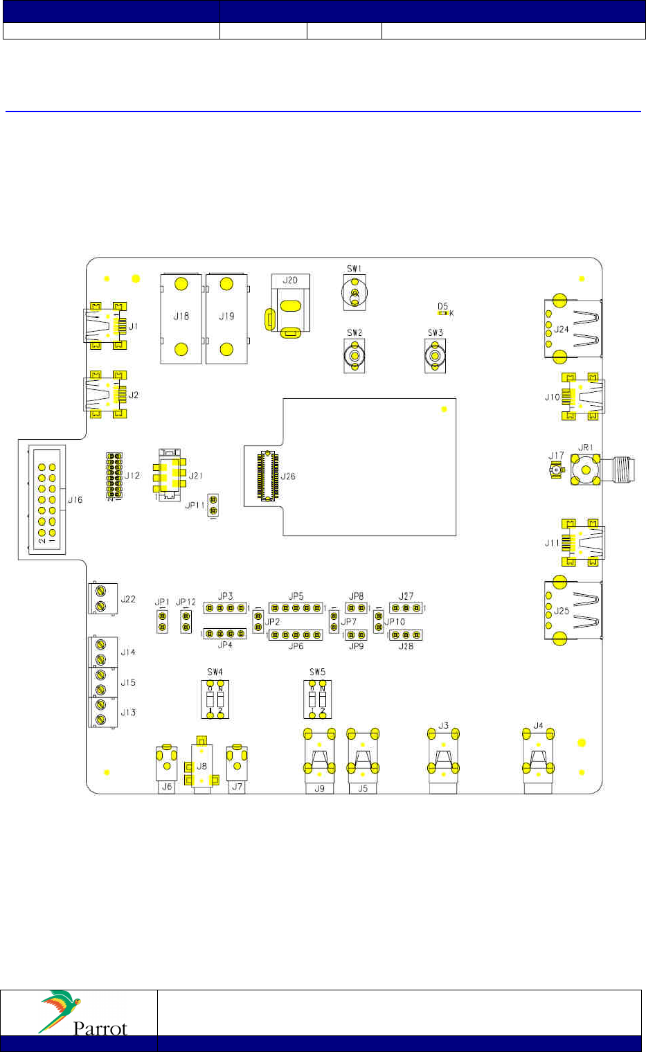
6 Development Tools
Demo board available
Host Software Interface specification
Host software example with C++ source code.
CK5050 WORKBENCH/TOP SIDE VIEW
Prepared
David COROLLEUR
Title
CK5050
+
Datasheet
Approved
Hocine BELKHOUDJA
Date
1
5
/04
/08
Revision
1.01
File
CK5050
+_Datasheet_1.03.doc
PROPRIETARY AND CONFIDENTIAL
The information contained in this document is the sole property of Parrot.
Any reproduction in part or as a whole without the written permission of Parrot is prohibited.
Project
CK5050+
Part Numbers
24
24
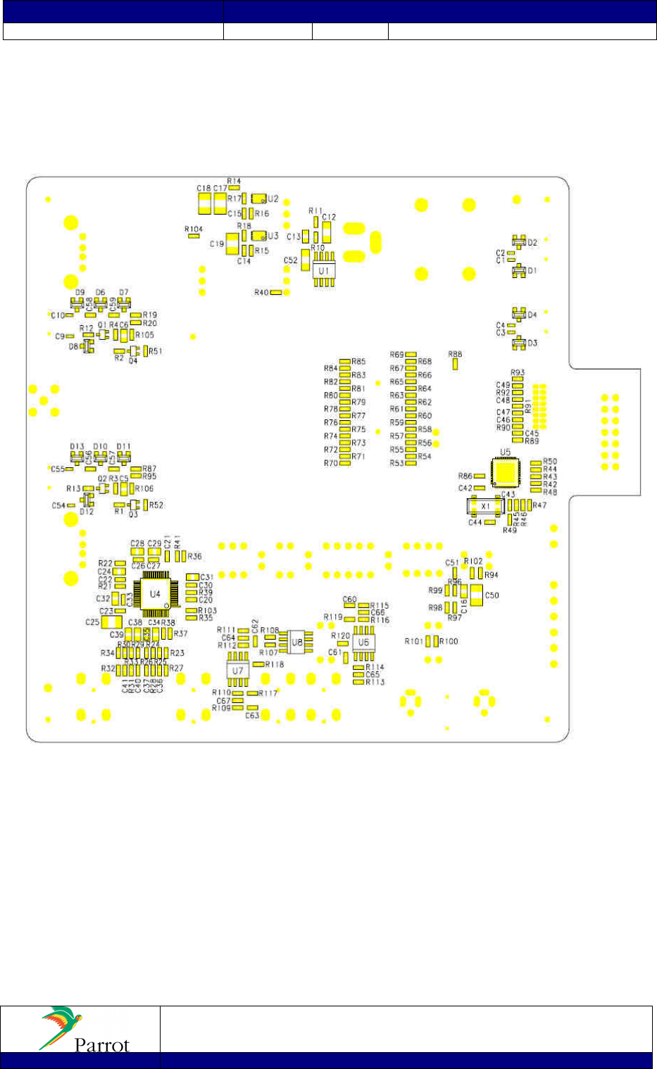
CK5050 WORKBENCH/BOTTOM SIDE VIEW (not released)

Prepared
David COROLLEUR
Title
CK5050
+
Datasheet
Approved
Hocine BELKHOUDJA
Date
1
5
/04
/08
Revision
1.01
File
CK5050
+_Datasheet_1.03.doc
PROPRIETARY AND CONFIDENTIAL
The information contained in this document is the sole property of Parrot.
Any reproduction in part or as a whole without the written permission of Parrot is prohibited.
Project
CK5050+
Part Numbers
25
25
7 FCC Requirements for module application
• CK5050+ with External Antenna (PI040114AA)
FCC ID: RKXCK5050PEA
In accordance with FCC Part 15, the CK5050+ is listed as a Limited Modular Transmitter device.
In support of the Modular Transmitter Approval, the following is stated:
• The module does have buffered modulation / data inputs.
• The module does regulate its own power supply.
• The module have its own RF shielding
• The module can be tested as a stand-alone device.
• The module is labeled with the proper FCC ID, and labeling instructions are provided to OEM end users
for external product labels.
• The module does have instruction for proper use.
• The module does meet the FCC RF regulations.
Limited Modular Transmitter Approval, is granted, instead of Modular Transmitter Approval, because the following
condition is not met:
• The module does not have a permanently attached antenna.
• The applicant of the final device into which the module CK5050+ is installed is not required to obtain a new
authorization for this. Moreover, module CK5050+ is also submitted to CE mark, Bluetooth certification, and is
considered is an automotive product. This product respects FCC part 15 C requirements for a Bluetooth application.
• Module CK5050+ is labelled with its own FCC number on its shielding, and, if the FCC ID is not visible when the
module is installed inside final device, then the outside of the device into which the module is installed must also
display a label referring to the enclosed module. This exterior label can use wording such as the following: “Contains
Transmitter Module FCC ID: RKXCK5050PEA” or “Contains FCC ID: RKXCK5050PEA.” Any similar wording
that expresses the same meaning may be used.
• Module CK5050+ can not be integrated in a final device which is connected to the AC power lines. It is necessary
that final device must be supplied by a battery.
• FCC RF exposure requirements: This device and its antenna(s) must not be collocated or operating in conjunction
with any other antenna or transmitter.
• THIS DEVICE COMPLIES WITH PART 15 OF THE FCC RULES. OPERATION IS SUBJECT TO THE
FOLLOWING TWO CONDITIONS:
(1) THIS DEVICE MAY NOT CAUSE HARMFUL INTERFERENCE, AND
(2) THIS DEVICE MUST ACCEPT ANY INTERFERENCE RECEIVED, INCLUDING
INTERFERENCE THAT MAY CAUSE UNDESIRED OPERATION.
NOTE: THE MANUFACTURER IS NOT RESPONSIBLE FOR ANY RADIO OR TV INTERFERENCE
CAUSED BY UNAUTHORIZED MODIFICATIONS TO THIS EQUIPMENT. SUCH MODIFICATIONS
COULD VOID THE USER’S AUTHORITY TO OPERATE THE EQUIPMENT.

Prepared
David COROLLEUR
Title
CK5050
+
Datasheet
Approved
Hocine BELKHOUDJA
Date
1
5
/04
/08
Revision
1.01
File
CK5050
+_Datasheet_1.03.doc
PROPRIETARY AND CONFIDENTIAL
The information contained in this document is the sole property of Parrot.
Any reproduction in part or as a whole without the written permission of Parrot is prohibited.
Project
CK5050+
Part Numbers
26
26
• CK5050+ with Internal Antenna (PI040123AA)
FCC ID: RKXCK5050PIA
In accordance with FCC Part 15, the CK5050+ is listed as a Modular Transmitter device.
In support of the Modular Transmitter Approval, the following is stated:
• The module does have buffered modulation / data inputs.
• The module does regulate its own power supply.
• The module have its own RF shielding
• The module can be tested as a stand-alone device.
• The module is labeled with the proper FCC ID, and labeling instructions are provided to OEM end users
for external product labels.
• The module does have instruction for proper use.
• The module does meet the FCC RF regulations.
• The module have a permanently attached antenna.
• The applicant of the final device into which the module CK5050+ is installed is not required to obtain a new
authorization for this. Moreover, module CK5050+ is also submitted to CE mark, Bluetooth certification, and is
considered is an automotive product. This product respects FCC part 15 C requirements for a Bluetooth application.
• Module CK5050+ is labelled with its own FCC number on its shielding, and, if the FCC ID is not visible when the
module is installed inside final device, then the outside of the device into which the module is installed must also
display a label referring to the enclosed module. This exterior label can use wording such as the following: “Contains
Transmitter Module FCC ID: RKXCK5050PIA” or “Contains FCC ID: RKXCK5050PIA.” Any similar wording
that expresses the same meaning may be used.
• Module CK5050+ cannot be integrated in a final device which is connected to the AC power lines. It is necessary
that final device must be supplied by a battery.
• FCC RF exposure requirements: This device and its antenna(s) must not be collocated or operating in conjunction
with any other antenna or transmitter.
• THIS DEVICE COMPLIES WITH PART 15 OF THE FCC RULES. OPERATION IS SUBJECT TO THE
FOLLOWING TWO CONDITIONS:
(1) THIS DEVICE MAY NOT CAUSE HARMFUL INTERFERENCE, AND
(2) THIS DEVICE MUST ACCEPT ANY INTERFERENCE RECEIVED, INCLUDING
INTERFERENCE THAT MAY CAUSE UNDESIRED OPERATION.
NOTE: THE MANUFACTURER IS NOT RESPONSIBLE FOR ANY RADIO OR TV INTERFERENCE
CAUSED BY UNAUTHORIZED MODIFICATIONS TO THIS EQUIPMENT. SUCH MODIFICATIONS
COULD VOID THE USER’S AUTHORITY TO OPERATE THE EQUIPMENT.

Prepared
David COROLLEUR
Title
CK5050
+
Datasheet
Approved
Hocine BELKHOUDJA
Date
1
5
/04
/08
Revision
1.01
File
CK5050
+_Datasheet_1.03.doc
PROPRIETARY AND CONFIDENTIAL
The information contained in this document is the sole property of Parrot.
Any reproduction in part or as a whole without the written permission of Parrot is prohibited.
Project
CK5050+
Part Numbers
27
27
8 CE DECLARATION
We, Parrot SA 174 quai de Jemmapes 75010 Paris France, declare under our sole responsibility that our product
(Parrot CK5050+) is in conformity with the Radio and Telecommunication equipment directive 1999/5/EC R&TTE
according to the essentials requirements and respect the norms listed bellow :
3.1-a) Electrical Safety EN60950-1:2001/A11:2004
EMF EN50371 (06/2002)
3.1-b) EMC EN301 489-17 V1.2.1
3.2 Radio EN300 328 V1.7.1
Paris, September 9th , 2008
Qualification Manager
Arezki Guerrab
.
28
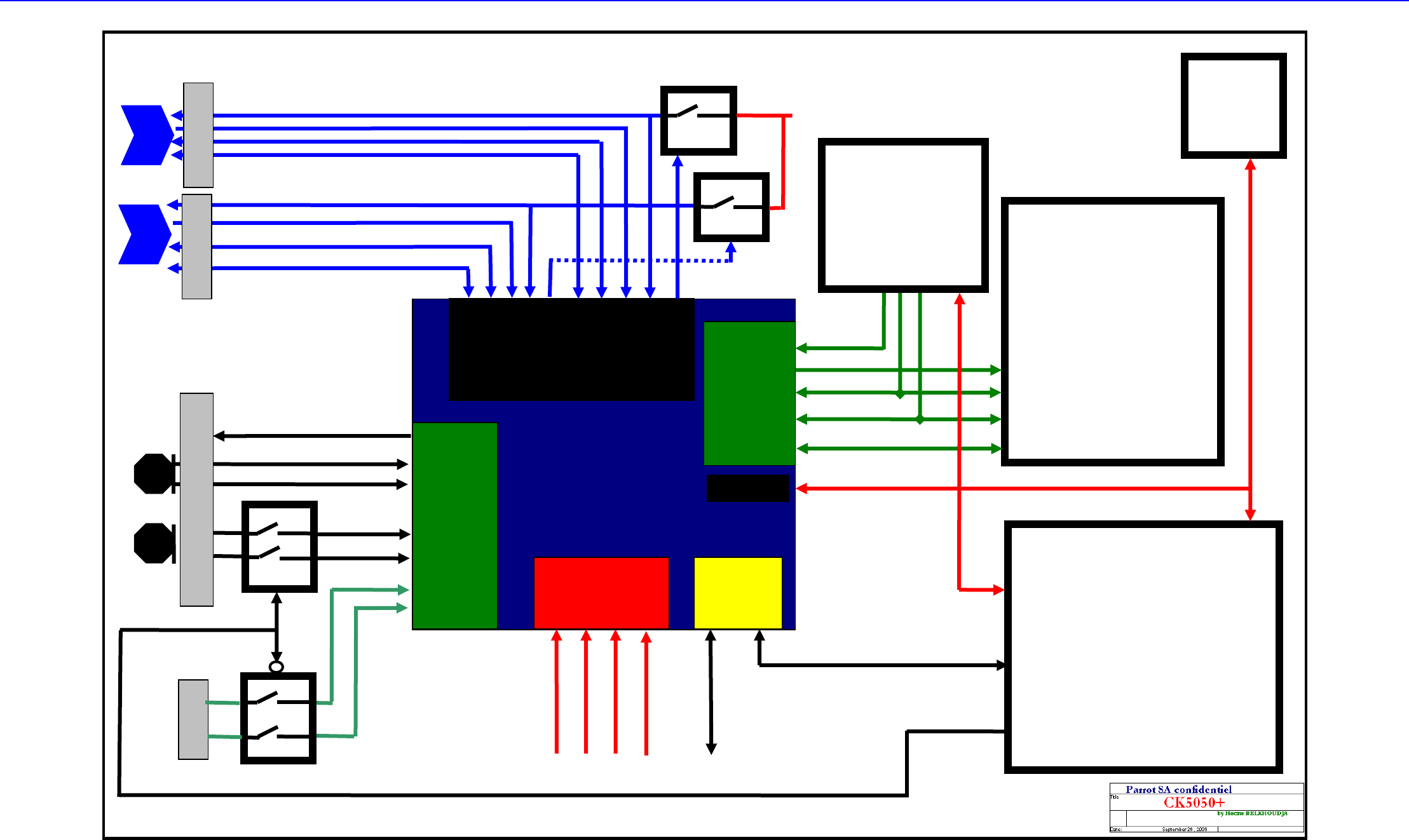
9 ANNEXE 1: CK5050+APPLICATION (example)
DSP Audio Processor
Parrot CK5050+
Microcontroller
UART1
UART0
MIC1
MIC1P
MIC1N
MIC2P
MIC2N
ADC
I2S
UART
I2S_IN
1
I2S_OUT
I2S_CLK
I2S_SYNC
Power
VCC
NRESET
VSS
P5+ Asic
SDRAM : 64 Mbits
Flash : 256 Mbits
Bluetooth 2.0 EDR
3.3V
Reset
Vss
CDRW
Integrated MP3/WMA
USB Co
nnector
I2S I2C
I2S
I2C
UART
USB 2.0 OTG
USB1_D+
USB1_D-
USB
1
_ID
USB1_VBUS
Drive Vbus
5V_USB
USB
1
_DRV_VBUS
Host AT commands and Flash Update
Apple
Authent.
IC
I2C
I2C
Debug Interface
I2S
_MCLK
USB Connector
USB0_D+
USB
0
_DRV_VBUS
USB0_D-
USB
0
_ID
USB
0
_VBUS
Drive Vbus
LINE IN
MICBIAS
Microphone
s
LIN
RIN
BOOTS
BOOTS
Audio input
Selection
: microphone inputs or
Line In
GPIO
MIC
2