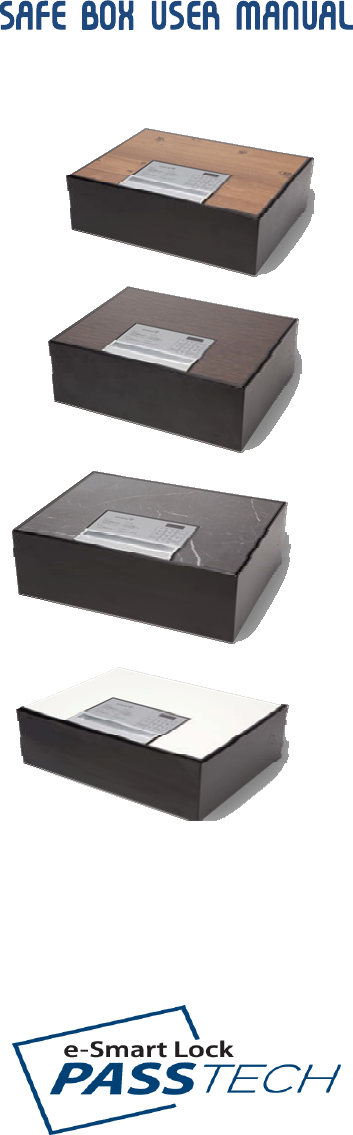
PASSTECH SB-100 Safebox User Manual passtech SB100 Manual

PASSTECH CO., LTD Safebox passtech SB100 Manual

Users Manual

  SAFE BOX USER MANUAL
 1. HOW TO USE SAFE BOX  SEQ.  Function  Operation 1  Initial setting  Safe box is unlocked entering password "1234" and   2  LOCK * with password     Press "RESET" button     Enter 4 digit password and press “LOCK” button..     Press “RESET” to cancel entering password.  * with card     Press "RESET" button     Place Guest Card on the “LOCK” of the safe box. 3  UNLOCK * With password     Safebox is unlocked entering 4 digit password     Press ‘RESET” button to cancel entering password..     The operation is on the halt for 30 minutes after       5 times wrong password entry. * With card     Press "RESET"  button     Place guest Card on the ‘LOCK’ of the Safe box.     Safebox is unlocked.     The operation is on the halt for 30 minutes after      5 times wrong password entry.  4  RELOCK Press "LOCK" button and safe box is locked. Previously  entered  password  is  valid  within  the  default  set time set by Setup settings after unlocking.
 2. HOW TO SET UP SAFE BOX  2.1 . General functions  - Safe box operates with card or password. - Systems cards for Safe box operation consist of Key Card, System Card, Guest Card and starts with pressing "RESET" button on the safe box. - Initial password is set as "1234" and new password is set with 4 digit. - Set necessary operational functions on the Setup Card before operating Safe box. - ‘SEr”  displays when the operational functions are missing and system is in the failure - “Err2”  displays when the operation or hardware function fails. 2.2 . Set-Up  - Necessary operational functions are set in the Setup Card. - Initial password is set as  “1234” - Warning sound beeps and  “SEr”  displays on the 7 segment when trying to use safe box without complete setup settings. - Safe box operates in the Free Mode, half-cycle mode.. - Password display is optional when locking (display as default) -   Password display is optional when unlocking (no display as default) - Operation  disabled  by  the  minutes  after  5  times  wrong  password entry  (default  15 min) - Lock the safe box by pressing “Relock” with same password previously  entered within the valid time set   * set RELOCK lapse time by the minute and as default ,   -    Time setting. -      Vender ID corresponds to hotel ID and Customer ID corresponds to Room number. -    Register Owner, Master Card -      Register upto 5 Master Cards.    3. SAFE BOX FUNCTIONS    3.1 User’s Function 3.1.1    Lock 1) Enter password and press  “LOCK”, when 7 Segment blinks 3 times.       Then confirmation melody of saved password sounds and displays ‘CLOS”       on the 7 segment. , 2) Lock the safe box by entering password only, without pressing "RESET".. 3) More than 5 seconds entry time lapse cancels the password input. 4) Pressing  “RESET”  during password entry cancels the input and have to retry..
 5) Warning signal sounds and  “Err2”  display on the 7 Segment if the safe box is not locked successfully.    3.1.2 Unlock   1) Enter password    and unlocked confirmation sounds and displays ‘OPEN”   on the      7 segment. , 2) Unlock the safe box by entering password only, without pressing "RESET".. 3) More than 5 seconds entry time lapse cancels the password input. 4) Pressing  “RESET”  during password entry cancels the input and have to retry.. 5) Warning signal sounds and  “Err2”  display on the 7 Segment if the safe box is not       unlocked    successfully.  3.1.3 Relock 1) Valid with password only 2) The safe box is locked with the same password previously entered by pressing ‘”RELOCK” within the set time.   3) Warning sounds and display  “Err2”  on the 7 segment if not locked successfully.  3.1.4 Count Down  1) Valid with password only. 2) After 5 times wrong password entries,  “Err1”  displays and warning sounds,       when  the  operation  of  the  safe  box  is  disabled  until  the  set  time  and  displays  the  time   count down    for 10 seconds. 3) Unlock with Master Card during the safe box disabled.
 4. DISPLAY MESSAGE  No  7 Segment Display  Function 1  CLOS  Lock the safe box 2  OPEN  Unlock the safe box 3  bAtt  Low battery 4  SEr  Operation failure or no settings 5  rtc  RTC(Real Time Clock) failure 6  Err1  Wrong password 7  Err2  Wrong operation or hardware failure 8  2910  Disabled Time Count down , e.g. ) remaining time 29 minutes, 10 seconds   9  ----  No display of entering password
 5. EMGERGENCY MEASURES No.  Message  Checklist  Action 1 Low  battery warning sound Check "bAtt" display on Check battery power Replace batteries 2  No power Check battery power Check the connection between    main and Front    panels Check Front Keypad status Replace batteries Connect Main and Front panels Replace Keypad   3 No password entered Confirm Keypad operation buzzer   Check connection  between  Main  and   Front panels. Check keypad Check 7 Segment display Connect Main and Front Replace Front   4  CLOSE failure Check battery power Check motor operation Check door, latch and stopper Replace batteries Replace or reinstall lock device 5  OPEN failure Check    if "Err1" displays on Reconfirm password entry Check if safe box is overload. Check Motor operation   Place  Master  Card  when  forgets the password Enter password while pressing door Open with emergency battery packEmergency break 6  Err1 display Confirm key enter sound on. Check Keypad   Place  Master  Card  when  forgets the password Replace Front   7  Ser display    Re-set LOCK with Setup Card Replace LOCK 8 7 Segment  Display smash   Replace Front   9  Operation disabled Check Count Down display    Disabled  for  30  minutes  after  5 times wrong password entry and   Unlock with Master Card
 6. Safebox SPECIFICATION Part  Component  Spec.  RemarkCPU  8-bit Microcontroller   Flash  32KBytes program memory   RAM  2KByte SRAM   EEPROM  1Kbytes   UART  1 programmable Serial   MCU Port  32 programmable I/O Lines   EEPROM  4kBytes, save 200 history records   RF Controller  13.56MHz, ISO 14443A / Mifare     Main RTC(Read  Time Clock)  Year, month, date, hour, minute, second   CPU  8-bit Microcontroller   Flash  8KBytes program memory   RAM  1KByte    SRAM   EEPROM  512Bytes   UART  1 programmable Serial   MCU Port  23 programmable I/O Lines   7 Segment  4 digits   Front Keypad  12Keys (10 number Key, RESET, LOCK)   Operating Voltage  DC 4.2V      (Battery 1.5V * 4 )   Power Power Consumption  standby 10uA,    max.280mA    [Safety warning] There is danger of explosion if the battery is inserted reversely. Power source: AA 1.5 V, 4 alkaline batteries are used.
FCC Part 15 Class B EquipmentThis equipment has been tested and found to comply with the limits for a Class B digital device, pursuant to Part 15 of the FCC Rules. These limits are designed to provide reasonable protection against harmful interference in a residential installation. This equipment generates, uses and can radiate radio frequency energy and, if not installed and used in accordance with the instructions, may cause harmful interference to radio communications. However, there is no guarantee that interference will not occur in a particular installation. If this equipment does cause harmful interference to radio or television reception, which can be determined by turning the equipment off and on, the user is encouraged to try to correct the interference by one or more of the following measures:• Reorient or relocate the receiving antenna.• Increase the separation between the equipment and receiver.• Connect the equipment into an outlet on a circuit different from that to which the receiver is connected.• Consult the dealer or an experienced radio/TV technician for help.FCC Information for UserThe users manual or instruction manual for an intentional or unintentional radiator shall caution the user that changes or modifications not expressly approved by the party responsible for compliance could void the user's authority to operate the equipment. In cases where the manual is provided only in a form other than paper, such as on a computer disk or over the Internet, the information required by this section may be included in the manual in that alternative form, provided the user can reasonably be expected to have the capability to access information in that form.

Navigation menu