PAX Technology PX7W Multi-Lane Payment Terminal User Manual PX7 W fcc
PAX Technology Limited Multi-Lane Payment Terminal PX7 W fcc
User manual
Reset Button and Audio Jack
7
Reset Button and Audio Jack
Mounting
Slots
Reset
Button
Audio Jack
If required, restart the terminal
by pressing in and holding the
reset button for 2-3 seconds.
Cable Lock
8
Cable Lock
If required, insert customer-provided
cable lock into K-Slot®. Loop cable
around permanent object to secure
in place.
Stand Installation
9
Stand Installation
PAX TECHNOLOGY INC.
Stylus Port
If required, a visually disabled
person can connect a headphone
to the terminal for audio prompting using the 3.5mm output
audio jack.
Route Cables
x
If required, the P terminal may be
mounted to a stand. Instructions
may vary depending on stand
specifications.
Carefully route the required cables
up through the stand pipe and out
the top. Connect the cables to the
x
P terminal ports.
Insert the three mounting slots on
the underside of the terminal into
the three metal prongs on the stand
base.
Slide the terminal firmly into position,
locking the terminal in place on the
stand. Secure with fastening screw
or locking device as required.
PAX TECHNOLOGY INC.
PAX TECHNOLOGY INC.
x
P termi nals that include a default commu nication
module come standard with one Et hernet port and RS 232,
USB, and PU SB network capabilities. However, if the
default commu nication mo dule is replaced with an optional
commu nication mo dule, your choice of these additional
netwo rk capabilities are available:
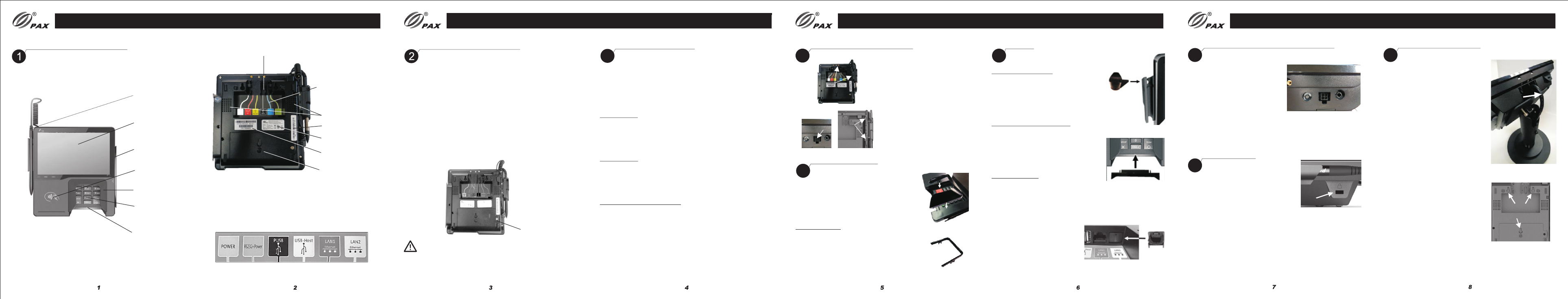
Communication Module
Communication Module Power Connections
Power Connections
3
PAX TECHNOLOGY INC.
Communication ports are labeled and color-coded:
Green Blue Black Yellow Red White
Product Description
Product Description
Stylus pen
Touch screen
Magnetic
stripe reader
Contactless
reader
Privacy shield
Keypad
Smart card
reader
Cable retention clips
Communication
ports
Speakers
MAC address label
Regulatory label
Communication
module
Part number/
serial number label
Power can be supplied via the power port or a single data cable
that carries power. This power can be provided via a “powered
cable” where the connected POS terminal provides the power
x
(i.e. PUSB or Power over Ethernet) or by connecting a P power
supply directly to the data cable (i.e. RS232 or USB).
1) Power Port
Insert the power connector into the green POWER port. Turn
the power connector, locking the tab behind the short plastic
wall.Dress the cable through the retention clips. A separate data
cable is also required.
2) POS Cable
Insert the cable connector into the appropriate port on the
terminal. Dress the cable through the retention clips opposite
the port. Connect power supply to cable as required.The cash
register could also supply power to terminal.
3) Power over Ethernet (PoE)
Power is available over the red LAN1 port when the optional
PoE and Ethernet hub communication module is installed.
• A second Et hernet port
• Power over Ethernet
• An Et hernet hub
• Wi-Fi and Bluetooth LE
• Wi-Fi and Cellular GS M
The commu nication module is located on the underside of
the termi nal.
Communication
module
A communication module must be installed before power can
be applied to the terminal. Once the new communication
module is properly installed, operate the terminal as usual.
WARNING:
Working Environment: Temperature -10°C~50°C (14°F~122°F)
R.H.: 10%~93% (non-condensing)
Storage Environment: Temperature -20°C~60°C (-4°F~140°F)
R.H.: 5%~95% (non-condensing)
Plugs
Plugs
6
1) Stylus Holder Plug
If required, to prevent stylus pen from
being inserted vertically into stylus
holder, firmly insert plug into opening
in holder, aligning with curve of stylus
holder.
2) Smart Card Reader Plug
If required, insert smart card reader
plug into smart card receptacle slot.
To remove, if required, gently pry out
the plug using a small screwdriver in
the slit along top of plug.
3) Ethernet Plug
An Ethernet plug is included in
case you want to block an inactive
LAN port. Align plug so that it
matches the shape of the port
and gently push into opening.
To remove, if required, gently
pry off using a small
screwdriver in the slit along
the top of the plug.
Note: LAN2 port is enabled only
when Ethernet hub or PoE and Ethernet hub
communication module is installed.
1) Stylus
Holder
Plug
2) Smart Card Reader Plug
3) Ethernet
Plug
1)
Mounting
Locations
2) Stylus Po rt 3)
Retention
Clips
1) Align stylus holder over metal
screw openings at left side or
top of terminal. Insert tabs into
indentations along edge. Attach
with captive screws.
2) Insert connector end of stylus
pen into stylus port on left side
of terminal.
3) Use enclosed plastic card to
press stylus cord into retention
clips on left side of terminal.
Privacy Shield
Privacy Shield
5
Insert tabs and snap shield firmly in place
to left and right of keypad. Not designed to
be removable. Removing the shield breaks
the retention tabs and the ability to remotely
track the status of the shield is lost.
1Privacy Shield
Decorative Plug
Decorative Plug – If a privacy shield is not
installed, a non-removable decorative plug
may be installed in its place. This plug does
not provide any PIN entry privacy.
CAUTION: If the privacy shield is not installed,
you must use PCI-approved alternative methods
to secure the PIN pad.
Stylus Holder and Pen
Stylus Holder and Pen
4
Payment Terminal
PAX TECHNOLOGY INC.
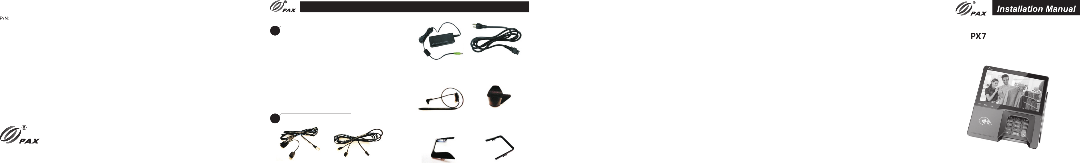
Available Accessories
Cleaning the Device
10
Cleaning the Device
WARNING:
Do not use industrial strength or abrasive cleaner as it may
damage or scratch the screen.
Do not immerse device in water (or liquid.)
Do not spray water or cleaner into the MSR slot, Smart Card
Reader or ports.
To clean screen, apply distilled water or mild glass cleaner
onto a soft, lint-free cloth and gently wipe terminal screen.
To clean terminal, apply distilled water or plastic-safe cleaner
onto a soft, lint-free cloth and gently wipe terminal.
11
Available Accessories
RS232 Cable
200204020000140
Requires Power Supply
USB Cable
200204020000141
Requires Power Supply
Power Supply
200310110000070
Requires Power Cord
Power Cord
200311020000023
Requires Power Supply
Stylus Pen
200209090000929
Stylus Holder Plug
200209090000930
Decorative Privacy
Shield Plug
2002090900001037
Privacy Shield
200209060000040
PAX TECHNOLOGY INC.
910
This docume nt is provided to you for informa tional purposes
only. All features and specifications are subject to change
without notice. PAX's name and PAX's logo are registered
tradema rks of PAX Technology Inc. All rights reserved.
PAX Technology Inc.
4901 Belfort Road, Suite 130
Jacksonville, FL 32256, US A
T: 877-859-0099
W: www.pax.us
E: sales@p ax.us
FCC Regulations:
This device complies with part 15 of the FCC Rules.
Operation is subject to the following two conditions: (1) This
device may not cause harmful interference, and (2) this
device must accept any interference received, including
interference that may cause undesired operation.
This device has been tested and found to comply with the
limits for a Class B digital device, pursuant to Part 15 of the
FCC Rules. These limits are designed to provide
reasonable protection against harmful interference in a
residential installation. This equipment generates, uses and
can radiated radio frequency energy and, if not installed and
used in accordance with the instructions, may cause
harmful interference to radio communications. However,
there is no guarantee that interference will not occur in a
particular installation If this equipment does cause harmful
interference to radio or television reception, which can be
determined by turning the equipment off and on, the user is
encouraged to try to correct the interference by one or more
of the following measures:
-Reorient or relocate the receiving antenna.
-Increase the separation between the equipment and
receiver.
-Connect the equipment into an outlet on a circuit
different from that to which the receiver is connected.
-Consult the dealer or an experienced radio/TV
technician for help.
Caution: Changes or modifications not expressly
approved by the party responsible for compliance could
void the user's authority to operate the equipment.
RF Exposure Information
This device meets the government's requirements for
exposure to radio waves.This device is designed and
manufactured not to exceed the emission limits for
exposure to radio frequency (RF) energy set by the
Federal Communications Commission of the U.S.
Government.
This device complies with FCC radiation exposure limits
set forth for an uncontrolled environment. In order to
avoid the possibility of exceeding the FCC radio
frequency exposure limits, human proximity to the
antenna shall not be less than 20cm (8 inches) during
normal operation.
11 12