PAYNE Package Units(both Units Combined) Manual L0610782
User Manual: PAYNE PAYNE Package Units(both units combined) Manual PAYNE Package Units(both units combined) Owner's Manual, PAYNE Package Units(both units combined) installation guides
Open the PDF directly: View PDF ![]() .
.
Page Count: 24
Installation Instructions
NOTE: Read the entire instruction manual before starting the
installation.
TABLE OF CONTENTS
Page
SAFETY CONSIDERATIONS ........................ 2
INTRODUCTION .................................. 2
RECEIVING AND INSTALLATION ................ 2-10
Check Equipment ................................. 2
Identify Unit ................................... 2
Inspect Shipment ................................ 2
Provide Unit Support .............................. 2
Slab Mount .................................... 2
Ground Mount ................................. 2
Provide Clearances ................................ 2
Place Unit ....................................... 2
Select and Install Ductwork .......................... 2
Configuring Units for Downflow (Vertical) Discharge . . . 3
Connect Condensate Drain .......................... 3
Install Electrical Connections ........................ 5
High-Voltage Connections ........................ 5
Routing Power Leads Into Unit ..................... 6
Connecting Ground Lead to Unit Ground ............. 6
Routing Control Power Wires ..................... 6
Accessory Electric Heat Wiring ..................... 6
PRE-START-UP ................................... 7
START-UP ..................................... 7-17
Check for Refrigerant Leaks ......................... 7
Start-Up Cooling and Make Adjustments ............... 7
Checking Cooling and Heating Control Operation ...... 7
Refrigerant Charge ................................ 8
No Charge ..................................... 8
Low Charge Cooling ............................. 8
Heating Mode Charge ............................ 8
Indoor Airflow and Airflow Adjustments ............... 8
Unit Controls .................................... 9
High-Pressure Relief Valve ........................ 9
Loss-of- Charge Switch .......................... 9
Compressor Overload ............................ 9
Compressor Rotation ............................. 9
Sequence of Operation ............................. 9
Fan Operation .................................. 9
A05194
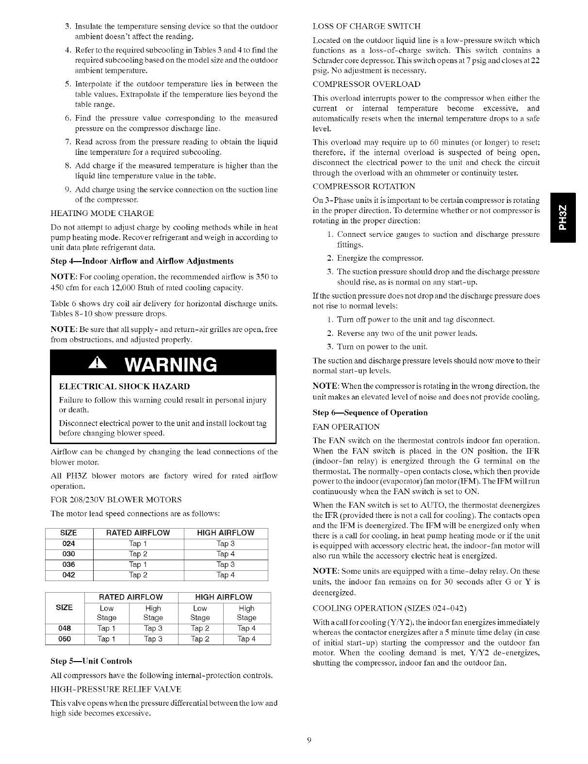
Fig. 1-Unit PH3Z
Cooling Operation ............................ 9, 17
Heating Operation .............................. 17
Continuous Fan ................................ 17
Defrost ...................................... 17
Electric Resistance Heating ....................... 17
MAINTENANCE ............................... 17-20
Air Filter ....................................... 18
Unit Top Removal ................................ 18
Indoor Blower and Motor .......................... 18
Outdoor (;oil, Indoor Coil. and Condensate Drain Pan .... 19
Outdoor Fan .................................... 19
Electrical Controls and Wiring ...................... 19
Refrigerant Circuit ................................ 20
Indoor Airflow .................................. 20
Metering Devices ................................ 20
Liquid Line Strainers .............................. 20
High Flow Valves ................................ 20
TROUBLESHOOTING ............................. 20
START-UP CHECKLIST ........................... 24
SAFETYCONSIDERATIONS
Installationandservicingofthisequipmentcanbehazardousdueto
mechanicalandelectricalcomponents.Onlytrainedandqualified
personnelshouldinstall,repair,orservicethisequipment.
Untrainedpersonnelcanperformbasicmaintenancefunctionssuch
ascleaningandreplacingairfilters.Allotheroperationsmustbe
performedbytrainedservicepersonnel.Whenworkingonthis
equipment,observeprecautionsintheliterature,ontags,andon
labelsattachedto orshippedwiththeunitandothersafety
precautionsthatmayapply.
Followallsafetycodes.Installationmustbeincompliancewith
localandnationalbuildingcodes.Wearsafetyglasses,protective
clothing,andworkgloves.Havefireextinguisheravailable.Read
theseinstructionsthoroughlyandfollowallwarningsorcautions
includedinliteratureandattachedtotheunit.
Recognizesafetyinformation.Thisisthesafety-alertsymbol'_.
Whenyouseethissymbolontheunitandininstructionsormanuals,
bealerttothepotentialforpersonalinjury.Understandthesesignal
words:DANGER.WARNING,andCAUTION.Thesewordsare
usedwiththesafety-alertsymbol.DANGERidentifiesthemostse-
rioushazardswhichwillresultinseverepersonalinjuryordeath.
WARNINGsignifieshazardswhichcouldresultinpersonalinjury
ordeath.CAUTIONisusedtoidentifyunsafepracticeswhichmay
resultinminorpersonalinjuryorproductandpropertydamage.
NOTEisusedtohighlightsuggestionswhichwillresultinen-
hancedinstallation,reliability,oroperation.
ELECTRICALSHOCKHAZARD
Failuretofollowthiswarningcouldresultinpersonalinjury
ordeath.
Beforeinstallingorservicingsystem,alwaysturnoffmain
powertosystem.Theremaybemorethanonedisconnect
switch.Turnoffaccessoryheaterpowerswitchifapplicable.
INTRODUCTION
ThePH3Zpackagedheatpumpis fullyself-containedand
designedforoutdoorinstallation(SeeFig.1).Standardunitsare
shippedinahorizontal-dischargeconfigurationforinstallationon
aground-levelslabordirectlyonthegroundiflocalcodespermit.
Standardunitscanbeconvertedtodownflow(vertical)discharge
configurationsfor rooftopapplicationswitha fieldsupplied
plenum.
RECEIVINGANDINSTALLATION
Stepl--Check Equipment
IDENTIFY UNIT
The unit model number and serial number are printed on the unit
informative plate. Check this information against shipping papers.
INSPECT SHIPMENT
Inspect for shipping damage while unit is still on shipping pallet. If
unit appears to be damaged or is torn loose from its anchorage, have
it examined by transportation inspectors before removal. Forward
claim papers directly to transportation company. Manufacturer is
not responsible for any damage incurred in transit. Check all items
against shipping list. Immediately notify the nearest Payne office if
any item is missing. To prevent loss or damage, leave all parts in
original packages until installation.
Step 2--Provide Unit Support
For hurricane tie downs, contact distributor for details and PE
(Professional Engineering) Certificate, if required.
SLAB MOUNT
Place the unit on a solid, level concrete pad that is a minimum of 4
in. thick with 2 in. above grade. The slab should extend
approximately 2 in. beyond the casing on all 4 sides of the unit. Do
not secure the unit to the slab except when required by local codes.
A 6-in. wide gravel apron should be used around the flat surface to
prevent airflow blockage by grass or shrubs. The unit should be
level To within 1/4 in. This is necessary for the unit drain to function
properly.
GROUND MOUNT
The unit may be installed either on a slab or placed directly on the
ground if local codes permit. Place the unit on level ground prepared
with gravel for condensate discharge.
Step 3--Provide Clearances
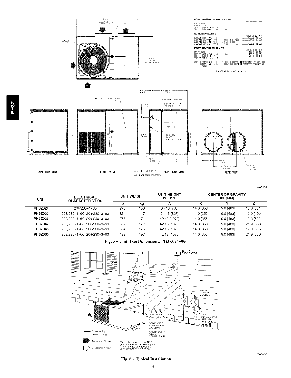
The required minimum service clearances are shown in Fig. 5.
Adequate ventilation and outdoor air must be provided.
The outdoor fan draws air through the outdoor coil and discharges
it through the top fan grille. Be sure that the fan discharge does not
recirculate to the outdoor coil. Do not locate the unit in either a
corner or under an overhead obstruction. The minimum clearance
under a partial overhang (such as a normal house overhang) is 48 in.
above the unit top. The maximum horizontal extension of a partial
overhang must not exceed 48 in.
IMPORTANT: Do not restrict outdoor airflow. An air restriction at
either the outdoor-air inlet or the fan discharge may be detrimental
to compressor life.
Do not place the unit where water, ice. or snow from an overhang
or roof will damage or flood the unit. Do not install the unit on
carpeting or other combustible materials. Slab-mounted units
should be at least 4 in. above the highest expected water and runoff
levels. Do not use unit if it has been under water.
Step 4--Place Unit
Unit can be moved with the rigging holds provided in the unit base.
Refer to Table 1 for operating weights. Use extreme caution to
prevent damage when moving the unit. Unit must remain in an
upright position during all moving operations. The unit nmst be
level within 1/4 in. for proper condensate drainage; the
ground-level pad must be level before setting the unit in place.
When a field-fabricated support is used. be sure that the support is
level and that it properly supports the unit.
Step 5--Select and Install Ductwork
The design and installation of the duct system must be in accordance
with the standards of the NFPA for installation of non-residence
type air conditioning and ventilating systems. NFPA 90A or
residence type, NFPA 90B and/or local codes and ordinances.
Select and size ductwork, supply- air registers, and return air grilles
according to ASHRAE (American Society of Heating,
Refrigeration, and Air Conditioning Engineers) recommendations.
Use the duct flanges provided on the supply- and return-air
openings on the side of the unit. See Fig. 5 for connection sizes and
locations. The 14-in. round duct collars are shipped inside the unit
attached to the base pan in the indoor blower compartment. They are
field-installed and must be removed from the indoor blower
compartment prior to start-up, even if they are not used for
installation.
Whendesigningandinstallingductwork,considertirefollowing: CONFIGURINGUNITSFORDOWNFLOW(VERTICAL)
DISCHARGE
UNITDAMAGEHAZARD
Failuretofollowthiscautionmayresultindamagetounit
components.
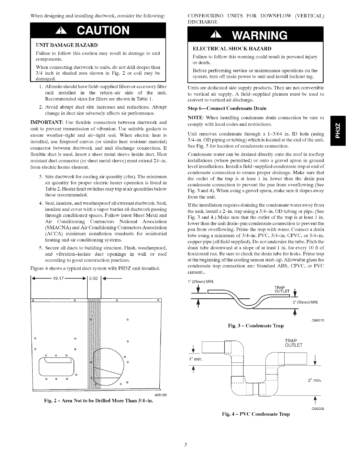
Whenconnectingductworktounits,donotdrilldeeperthan
3/4inchinshadedareashowninFig.2orcoilmaybe
damaged.
1.Allunitsshouldhavefield-suppliedfiltersoraccessoryfilter
rackinstalledin the return-airsideof the unit.
ReconmmndedsizesforfiltersareshowninTable1.
2.Avoidabruptductsizeincreasesandreductions.Abrupt
changeinductsizeadverselyaffectsairperformance.
IMPORTANT:Useflexibleconnectorsbetweenductworkand
unittopreventtransmissionofvibration.Usesuitablegasketsto
ensureweather-tightandair-tightseal.Whenelectricheatis
installed,usefireproofcanvas(orsimilarheatresistantmaterial)
connectorbetweenductworkandunitdischargeconnection.If
flexibleductisused,insertasheetmetalsleeveinsideduct.Heat
resistantductconnector(orsheetmetalsleeve)mustextend24-in.
fromelectricheaterelement.
3.Sizeductworkforcoolingairquantity(cfm).Theminimum
airquantityforproperelectricheateroperationislistedin
Table2.Heaterlimitswitchesmaytripatairquantitiesbelow
thoserecommended.
4.Seal,insulate,andweatherproofallexternalductwork.Seal,
insulateandcoverwithavaporbarrierallductworkpassing
throughconditionedspaces.FollowlatestSheetMetaland
Air ConditioningContractorsNationalAssociation
(SMACNA)andAirConditioningContractorsAssociation
(ACCA)minimuminstallationstandardsforresidential
heatingandairconditioningsystems.
5.Secureallductstobuildingstructure.Flash,weatherproof,
andvibration-isolateductopeningsin wallor roof
accordingtogoodconstructionpractices.
Figure4showsatypicalductsystemwithPH3Zunitinstalled.
•,_-._ 19.17 -----------_ _---
o
o
o
o
o
o o o
0O O
A05195
Fig. 2 -Area Not to be Drined More Than 3/4-in.
ELECTRICAL SHOCK HAZARD
Failure to follow this warning could result in personal injury
or death.
Before performing service or maintenance operations on the
system, turn off main power to unit and install lockout tag.
Units are dedicated side supply products. They are not convertible
to vertical air supply. A field-supplied plenum must be used to
convert to vertical air discharge.
Step 6--Connect Condensate Drain
NOTE: When installing condensate drain connection be sure to
comply with local codes and restrictions.
Unit removes condensate through a 1-3/64 in. ID hole (using
3/4-in. OD piping or tubing) which is located at the end of the unit.
See Fig. 5 for location of condensate connection.
Condensate water can be drained directly onto tire roof in rooftop
installations (where permitted) or onto a gravel apron in ground
level installations. Install a field-supplied condensate trap at end of
condensate connection to ensure proper drainage. Make sure that
the outlet of the trap is at least 1 in. lower than the drain pan
condensate connection to prevent the pan from overflowing (See
Fig. 3 and 4). When using a gravel apron, make sure it slopes away
from the unit.
If the installation requires draining the condensate water away from
the unit, install a 2-in. trap using a 3/4-in. OD tubing or pipe. (See
Fig. 3 and 4.) Make sure that the outlet of the trap is at least 1 in.
lower than the unit drain-pan condensate connection to prevent the
pan from overflowing. Prime the trap with water. Connect a drain
tube using a minimum of 3/4-in. PVC, 3/4-in. CPVC, or 3/4-in.
copper pipe (all field supplied). Do not undersize the tube. Pitch the
drain tube downward at a slope of at least 1 in. for every 10 ft of
horizontal run. Be sure to check the drain tube for leaks. Prinm trap
at the beginning of the cooling season start-up. Allowable glues for
condensate trap connection are: Standard ABS, CPVC, or PVC
cenmnt..
1" (25mm) MIN.
r'_,. TRAP ET ___
X_ 2"(50mm)MIN.
099013
Fig. 3 -Condensate Trap
TRAP
OUTLET
2" min.
Fig. 4- PVC Condensate Trap
C00009
OUIDOOR
COIL
LEFT SIDE VIEW
BOITO_ OF U_IT I_DO0_
t
g12fl
[3199_
_0110_ 0F UNII
_GU_ CLEARANCESTO CO_5T_LE MATL
lop o} _ o
SIDE 6_ _[_ OPPOSHED_C_ OPENINGS 0
NEC._E_ED_L_3R_.
6ROU_£_ S_RFAC_S PO_ER t_ SI_E _OG68 [42 00_
SIDEO_ _T OPPOS]_[ DUCTOP[NI_GS ........ _2 0[_000)
UNIT
PH3Z024
PH3Z030
PH3Z036
PH3Z042
PH3Z048
PH3Z060
A05201
ELECTRICAL
CHARACTERISTICS
208/230-1-60
208/230-1-60, 208/230-3-60
208/230-1-60, 208/230-3-60
208/230-1-60, 208/230-3-60
208/230-1-60, 208/230-3-60
208/230-1-60, 208/230-3-60
UNIT WEIGHT
Ib kg
283 133
324 147
377 171
389 177
384 175
433 197
UNIT HEIGHT
IN. [MM]
A
30.13 [765]
34.13 [867]
42.13 [10701
42.13 [1070]
42.13 [1070]
42.13 [1070]
CENTER OF GRAVITY
IN. [MM]
X Y
14.0 [356] 19.0 [483]
14.0 [356] 19.0 [483]
14.0 [356] 19.0 [483]
14.0 [356] 19.0 [483]
14.0 [356] 19.0 [483]
14.0 [356] 19.0 [483]
z
15.0 [381]
16.0 [4061
19.8[503]
21.9 [556]
19.8[503]
21.9 [556]
Fig. 5-Unit Base Dimensions, PH3Z024-060
-- Power WMng
-- Control Widng
_ ondenser Airflow
Evaporator Airflow
DRAIN
CONNECTION
"Separate disconnect per NEC
National Electrical Code required
i_r e ectr c heater when s ng e-
point connection is not used
Fig. 6 -Typical Installation
(UNIT AND
C00008
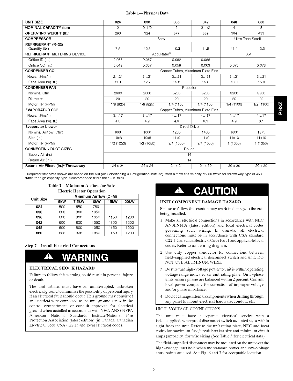
Table l--Physical Data
UNIT SIZE 024 030 036 042 048 060
NOMINAL CAPACITY (ton) 2 2- 1/2 3 3 -1/2 4 5
OPERATING WEIGHT (lb.) 293 324 377 389 384 433
COMPRESSOR Scroll Ultra Tech Scroll
REFRIGERANT (R-22)
Quantity (lb.) 7.5 10.3 11.4 13.3
REFRIGERANT METERING DEVICE TXV
0.067 0.067
0.049 0.057 0.070 0.073
Orifice ID (in.)
Orifice OD (in.)
CONDENSER COIL
Rows... Fins/in.
Face Area (sq. ft.)
CONDENSER FAN
Nominal Cfm
Diameter
Motor HP (RPM)
EVAPORATOR COIL
Rows... Fins/in.
Face Area (sq. ft.)
Evaporator blower
Nominal Airflow (Cfm)
Size (in.)
Motor HP (RPM)
CONNECTING DUCT SIZES
Supply Air (in.)
Return Air (in.)
Return-Air Filters (in.)* Throwaway
2...21 2...21 2...21 2...21
11.1 12.7 13.3 15.8
2600
20
1/8 (825)
2600
20
1/8 (825)
32OO
2O
1/4 (t100)
33OO
2O
1/2 (t100)
3...17 3...17 4...17 4...17
4.3 4.9 4.9 6.1
8OO
10x8
1/2 (t050)
10.3 11.9
AccuRater ®
0.082 0.086
0.059 0.063
Copper Tubes, Aluminum Plate Fins
2...21 2...21
15.8 15.8
Propeller
3200 3200
20 20
1/4 (1100) 1/4 (t100)
Copper Tubes, Aluminum Plate Fins
4...17 4...17
4.9 6.1
Direct Drive
1200 1400
11x9 11x9
3/4 (1050) 3/4 (1050)
Round
14
14
24 x 24 24 x 30
16OO
11x10
1 (1050)
1000
10x8
1/2 (t050)
1875
11x10
1(1050)
24 x 24 24 x 24 30 x 30 30 x 30
*Required filter sizes shown are based on the ARI (Air Conditioning & Refrigeration Institute) rated airflow at a velocity of 300 ft/min for throwaway type or 450
ff/min for high capacity type. Recommended filters are I -in. thick.
Table 2--Minimum Airflow for Safe
Electric Heater Operation
Unit Size Minimum Airflow (CFM)
5kW 7.5kW 10kW 15kW 20kW
024 500 650 750
030 600 800 1050
036 600 800 1050 1150 1200
042 600 800 1050 1150 1200
048 600 800 1050 1150 1200
060 600 800 1050 1150 1200
UNIT COMPONENT DAMAGE HAZARD
Failure to follow this caution may result in damage to the unit
being installed.
1. Make all electrical connections in accordance with NEC
ANSI/NFPA (latest edition) and local electrical codes
governing such wiring. In Canada, all electrical
connections must be in accordance with CSA standard
(;22. i Canadian Electrical ('ode Part iand applicable local
codes. Refer to unit wiring diagram.
2. Use only copper conductor for connections between
field-supplied electrical disconnect switch and unit. DO
NOT USE ALUMINUM WIRE.
3. Be sure that high-voltage power to unit is within operating
voltage range indicated on unit rating plate. On 3-phase
units, ensure phases are balanced within 2 percent. Consult
local power company for correction of improper voltage
and/or phase imbalance.
4. Do not damage internal components when drilling through
any panel to mount electrical hardware, conduit, etc.
HIGH-VOLTAGE CONNECTIONS
The unit must have a separate electrical service with a
field-supplied, waterproof disconnect switch mounted at, or within
sight from the unit. Refer to the unit rating plate. NEC and local
codes for maxinmm fuse/circuit breaker size and minimum circuit
amps (ampacity) for wire sizing (See Table 5 for electrical data).
The field-supplied disconnect may be mounted on the unit over the
high-voltage inlet hole when the standard power and low-voltage
entry points are used. See Fig. 6 and 7 for acceptable location.
Step 7--Install Electrical Connections
ELECTRICAL SHOCK HAZARD
Failure to follow this warning could result in personal injury
or death.
The unit cabinet must have an uninterrupted, unbroken
electrical ground to minimize the possibility of personal injury
if an electrical fault should occur. This ground may consist of
an electrical wire connected to the unit ground screw in the
control compartment, or conduit approved for electrical
ground when installed in accordance with NEC, ANSI/NFPA
American National Standards Institute/National Fire
Protection Association (latest edition) (in Canada. Canadian
Electrical Code CSA (;22.1) and local electrical codes.
Operationofunitonimproperlinevoltageconstitutesabuseand
maycauseunitdamagethatcouldaffectwarranty.
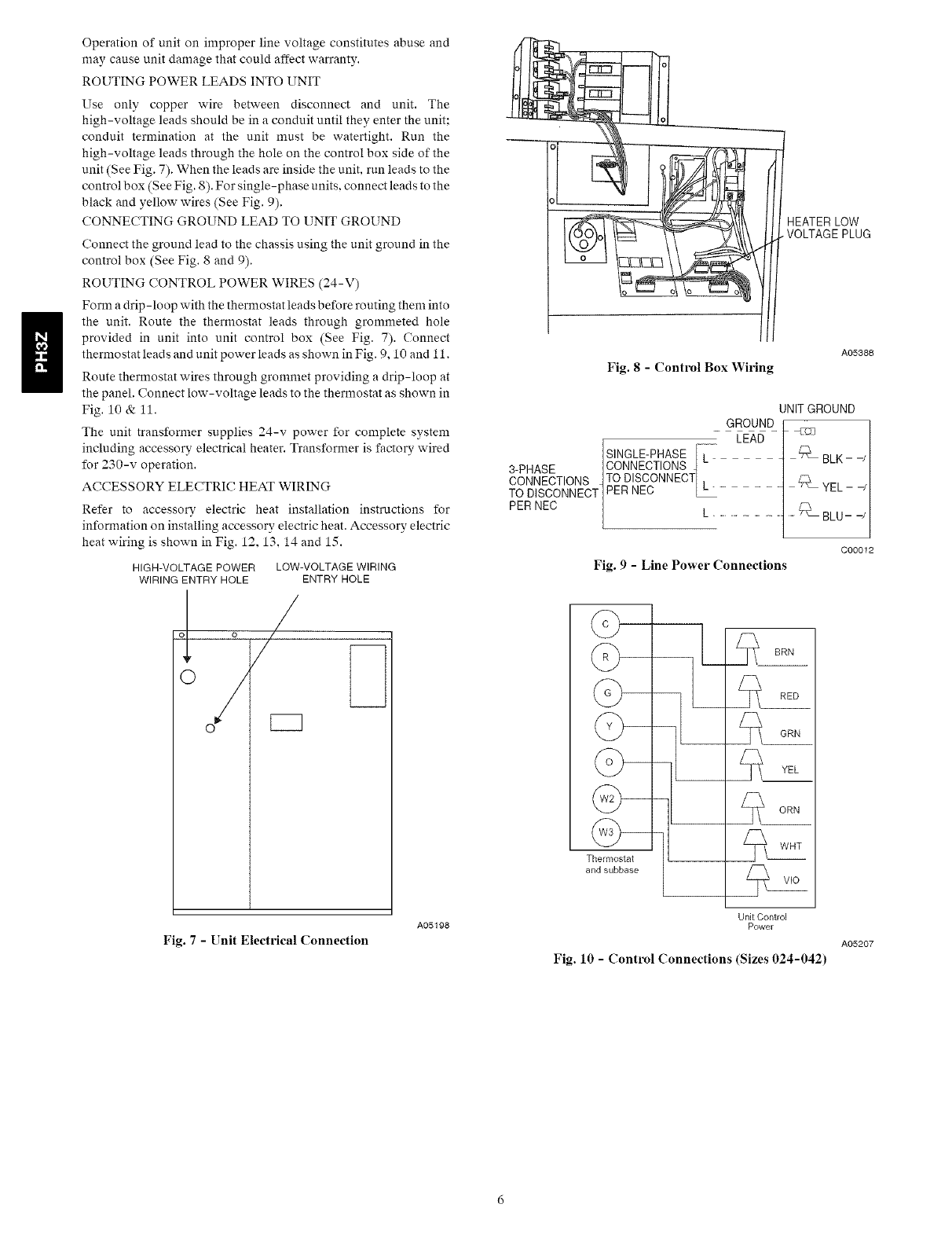
ROUTINGPOWERLEADSINTOUNIT
Useonlycopperwirebetweendisconnectandunit.The
high-voltageleadsshouldbeinaconduituntiltheyentertheunit;
conduitterminationattheunitmustbewatertight.Runthe
high-voltageleadsthroughtheholeonthecontrolboxsideofthe
unit(SeeFig.7).Whentheleadsareinsidetheunit,runleadstothe
controlbox(SeeFig.8).Forsingle-phaseunits,connectleadstothe
blackandyellowwires(SeeFig.9).
CONNECTINGGROUNDLEADTOUNITGROUND
Connectthegroundleadtothechassisusingtheunitgroundinthe
controlbox(SeeFig.8and9).
ROUTINGCONTROLPOWERWIRES(24-V)
Formadrip-loopwiththethermostatleadsbeforeroutingtheminto
theunit.Routethethermostatleadsthroughgrommetedhole
providedin unitintounitcontrolbox(SeeFig.7).Connect
thermostatleadsandunitpowerleadsasshowninFig.9,10and11.
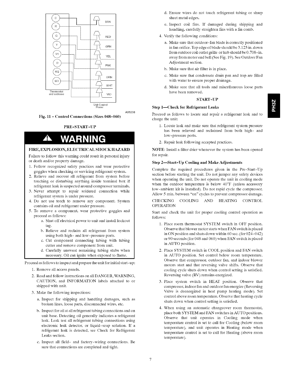
Routethermostatwiresthroughgrommetprovidingadrip-loopat
thepanel.Connectlow-voltageleadstothethermostatasshownin
Fig.10&11.
Theunittransformersupplies24-vpowerforcompletesystem
includingaccessoryelectricalheater.Transformerisfactorywired
for230-voperation.
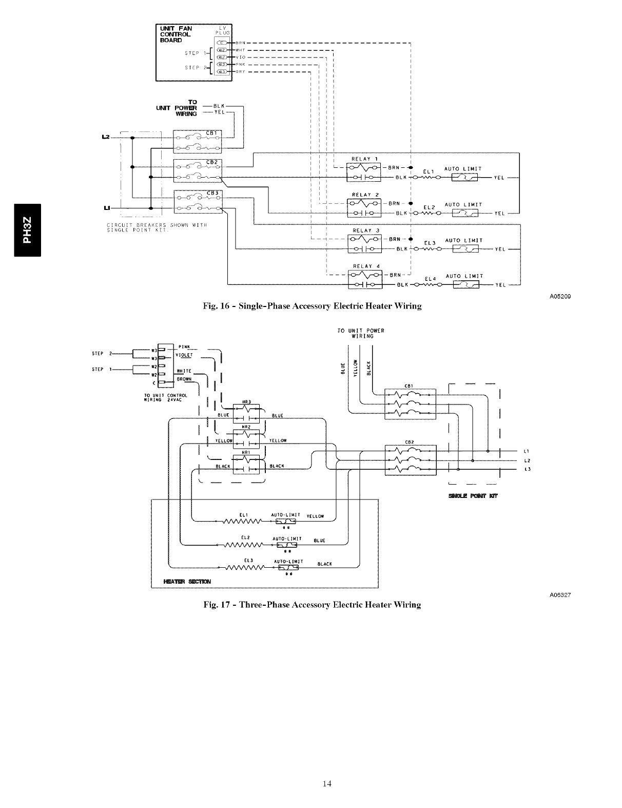
ACCESSORYELECTRICHEATWIRING
Referto accessoryelectricheatinstallationinstructionsfor
informationoninstallingaccessoryelectricheat.Accessoryelectric
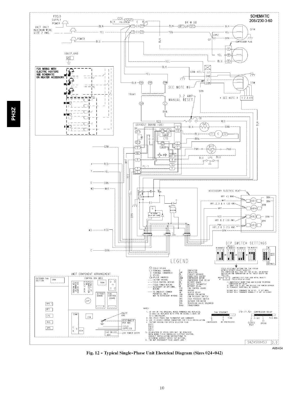
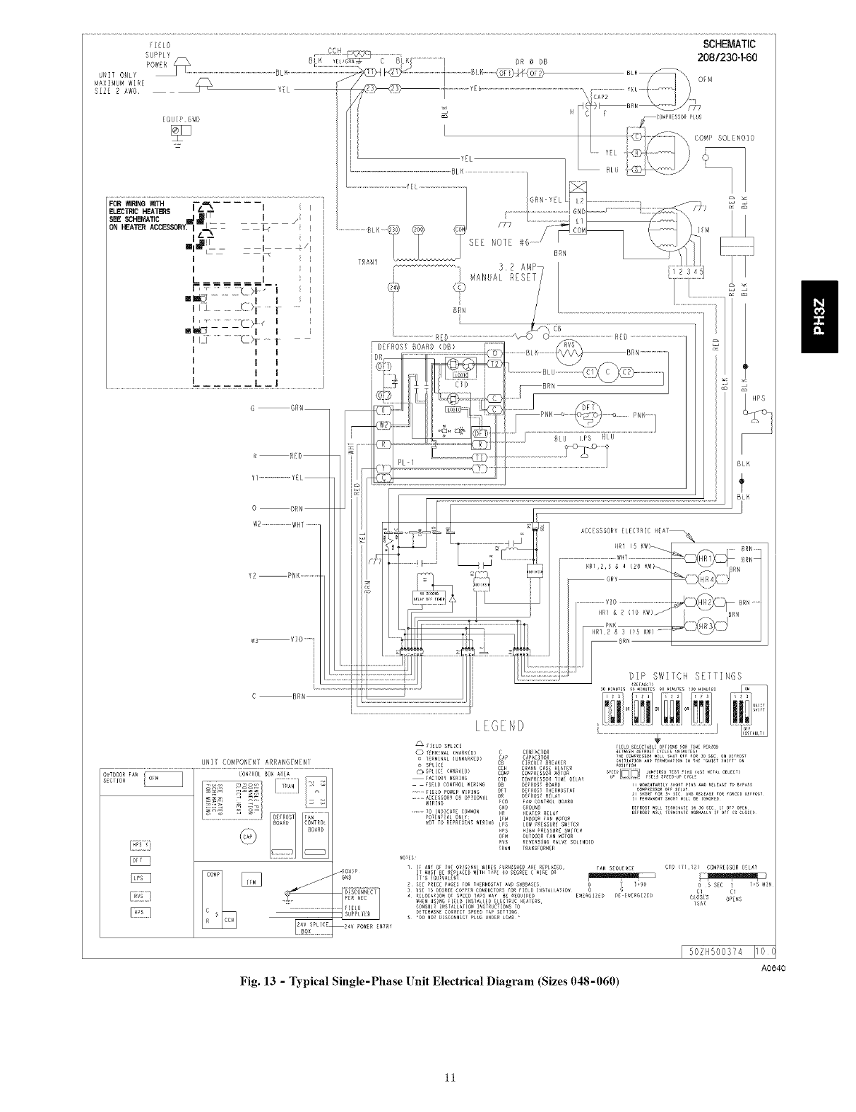
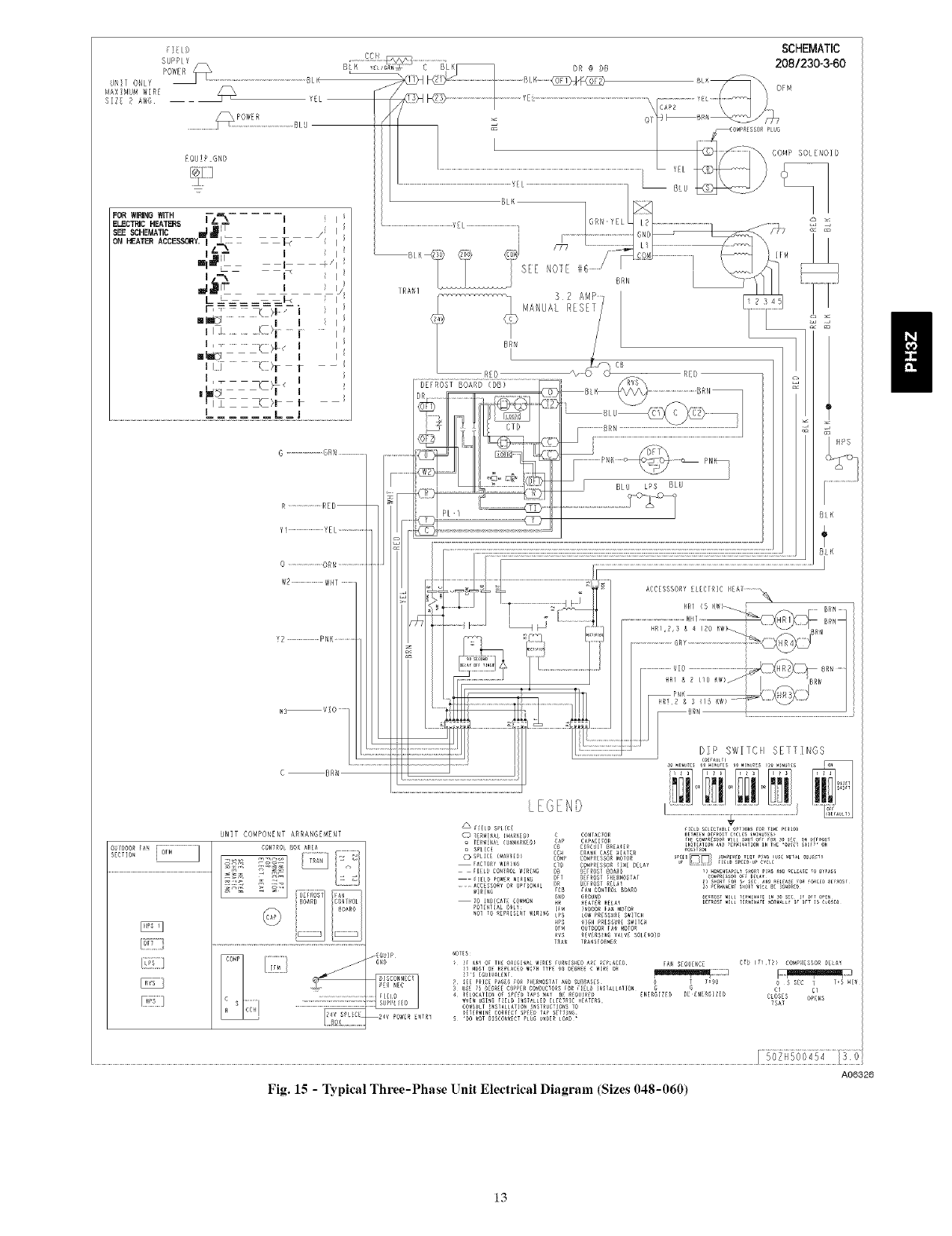
heatwiringisshowninFig.12,13,14and15.
HIGH-VOLTAGE POWER LOW-VOLTAGE WIRING
WIRING ENTRY HOLE ENTRY HOLE
o; o//
°o/
3-PHASE
CONNECTIONS
TO DISCONNECT
PER NEC
Fig. 8 - Control Box Widng
HEATER LOW
•VOLTAGE PLUG
A05388
UNIT GROUND
GROUND
LEAD
SINGLE-PHASE Z_ BLK- w
CONNECTIONS
TO DISCONNEC_
PERNEC L_ ...... _YEL-
L ................................_:Z_BLU-
Fig. 9 -Line Power Connections
L
Thermostat
and subbase
CO00i2
._ BRN
RED
GRN
Fig. 7 - Unit Electrical Connection
A05198 Unit Control
Power
Fig. 10 IControl Connections (Sizes 024-042)
A05207
@-
__
Thermostat
and subbase
Unit Control
Power
Fig. 11 - Control Connections (Sizes 048-060)
PRE- START- UP
A05208
FIRE, EXPLOSION, ELECTRICAL SHOCK HAZARD
Failure to follow this warning could result in personal injury
or death and/or property damage.
1. Follow recognized safety practices and wear protective
goggles when checking or servicing refrigerant system.
2. Relieve and recover all refrigerant from system before
touching or disturbing anything inside tenninal box if
refrigerant leak is suspected around compressor terminals.
3. Never attempt to repair soldered connection while
refrigerant system is under pressure.
4. Do not use torch to remove any component. System
contains oil and refrigerant under pressure.
5. To remove a component, wear protective goggles and
proceed as follows:
a. Shut off electrical power to unit and install lockout
tag.
b. Relieve and reclaim all refrigerant from system
using both high- and low-pressure ports.
c. Cut component connecting tubing with tubing
cutter and remove component from unit.
d. Carefully unsweat remaining tubing stubs when
necessary. Oil can ignite when exposed to flame.
Proceed as follows to inspect and prepare the unit for initial start- up:
1. Remove all access panels.
2. Read and follow instructions on all DANGER, WARNING.
CAUTION. and INFORMATION labels attached to or
shipped with unit.
3. Make the following inspections:
a. Inspect for shipping and handling damages, such as
broken lines, loose parts, disconnected ,,vires, etc.
b. Inspect for oil at all refrigerant tubing connections and on
unit base. Detecting oil generally indicates a refrigerant
leak. Leak test all refrigerant tubing connections using
electronic leak detector, or liquid-soap solution. If a
refrigerant leak is detected, see Check for Refrigerant
Leaks section.
c. Inspect all field- and factory-wiring connections. Be
sure that connections are completed and tight.
d. Ensure wires do not touch refrigerant tubing or sharp
sheet metal edges.
e. Inspect coil fins. If damaged during shipping and
handling, carefully straighten fins with a fin comb.
4. Verify the following conditions:
a. Make sure that outdoor-fan blade is correctly positioned
in fan orifice. Top edge of blade should be 3.125 in. down
from outdoor coil outlet grille or hub should be 0.708-in.
away from motor end bell (See Fig. 19). See Outdoor Fan
Adjustment section.
b. Make sure that air filter is in place.
c. Make sure that condensate drain pan and trap are filled
with water to ensure proper drainage.
d. Make sure that all tools and miscellaneous loose parts
have been removed.
START-UP
Step 1--Check for Refrigerant Leaks
Proceed as follows to locate and repair a refrigerant leak and to
charge the unit:
1. Locate leak and make sure that refrigerant system pressure
has been relieved and reclaimed from both high- and
low-pressure ports.
2. Repair leak following accepted practices.
NOTE: Install a filter drier whenever the system has been opened
for repair.
Step 2--Start-Up Cooling and Make Adjustments
Complete the required procedures given in the Pre-Start-Up
section before starting the unit. Do not jumper any safety devices
when operating the unit. Do not operate the unit in cooling mode
when the outdoor temperature is below 40°F (unless accesso_
low-ambient kit is installed). Do not rapid cycle the compressor.
Allow 5 min. between "on" cycles to prevent compressor damage.
CHECKING COOLING AND HEATING CONTROL
OPERATION
Start and check the unit for proper cooling control operation as
follows:
1. Place room thermostat SYSTEM switch in OFF position.
Observe that blower motor starts when FAN switch is placed
in ON position and shuts down within 60 sec. (for 024-042)
or 90 seconds (for 048 and 060) when FAN switch is placed
in AUTO position.
2. Place SYSTEM switch in COOL position and FAN switch
in AUTO position. Set control below room temperature.
Observe that compressor, outdoor fan, and indoor blower
motors start and that reversing valve shifts. Observe that
cooling cycle shuts down when control setting is satisfied.
Reversing valve (RV) remains energized.
3. Place system switch in HEAT position. Observe that
compressor, indoor fan and outdoor fan energize (Reversing
Valve is deenergized in heat pump heating mode). Set
control above room temperature. Observe that heating cycle
shuts down when control setting is satisfied.
4. When using an automatic changeover room thermostat,
place both SYSTEM and FAN switches in AUTO positions.
Observe that unit operates in Cooling mode when
temperature control is set to call for Cooling (below room
temperature), and unit operates in Heating mode when
temperature control is set to call for Heating (above room
temperature).
Mode[ Size
048
O6O
75 (24)
17.5 (9.7)
21 (11.7)
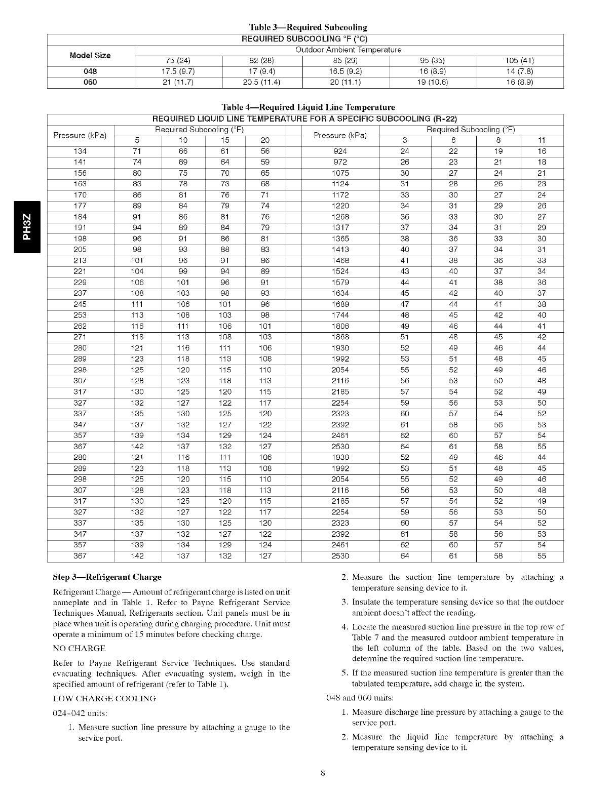
Table 3--Required Subcooling
REQUIRED SUBCOOLING °F (°C)
Outdoor Ambient Temperature
82 (28) 85 (29)
17 (9.4) 16.5 (9.2)
20.5 (11.4) 20 (11.1)
95 (35)
16 (8.9)
19 (10.6)
105 (41)
14 (7.8)
16 (8.9)
Pressure (kPa)
134
141
156
163
17O
177
184
191
198
2O5
213
221
229
237
245
253
262
271
28O
289
298
3O7
317
327
337
347
357
367
28O
289
298
3O7
317
327
337
347
357
367
5
71
74
8O
83
86
89
91
94
96
98
101
104
106
108
111
113
116
118
121
123
125
128
130
132
135
137
139
142
121
123
125
128
130
132
135
137
139
142
Table 4--Required Liquid Line Temperature
REQUIRED LIQUID LINE TEMPERATURE FOR ASPECIFIC SUBCOOLING (R-22)
Required Subcooling (°F)
10 15
66 61
69 64
75 70
78 73
81 76
84 79
86 81
89 84
91 86
93 88
96 91
99 94
101 96
103 98
106 101
108 103
111 106
113 108
116 111
118 113
120 115
123 118
125 120
127 122
130 125
132 127
134 129
137 132
116 111
118 113
120 115
123 118
125 120
127 122
130 125
132 127
134 129
137 132
Pressure (kPa)
20
56 924
59 972
65 1075
68 1124
71 1172
74 1220
76 1268
79 1317
81 1365
83 1413
86 1468
89 1524
91 1579
93 1634
96 1689
98 1744
101 1806
103 1868
106 1930
108 1992
110 2054
113 2116
115 2185
117 2254
120 2323
122 2392
124 2461
127 2530
106 1930
108 1992
110 2054
113 2116
115 2185
117 2254
120 2323
122 2392
124 2461
127 2530
3
24
26
3O
31
33
34
36
37
38
4O
41
43
44
45
47
48
49
51
52
53
55
56
57
59
6O
61
62
64
52
53
55
56
57
59
6O
61
62
64
Required Subcooling (°F)
6 8
22 19
23 21
27 24
28 26
30 27
31 29
33 30
34 31
36 33
37 34
38 36
40 37
41 38
42 40
44 41
45 42
46 44
48 45
49 46
51 48
52 49
53 50
54 52
56 53
57 54
58 56
60 57
61 58
49 46
51 48
52 49
53 50
54 52
56 53
57 54
58 56
60 57
61 58
11
16
18
21
23
24
26
27
29
3O
31
33
34
36
37
38
4O
41
42
44
45
46
48
49
5O
52
53
54
55
44
45
46
48
49
5O
52
53
54
55
Step 3--Refrigerant Charge
Refrigerant Charge --Amount of refrigerant charge is listed on unit
nameplate and in Table 1. Refer to Payne Refrigerant Service
Techniques Manual, Refrigerants section. Unit panels must be in
place when unit is operating during charging procedure. Unit must
operate a minimum of 15 minutes before checking charge.
NO CHARGE
Refer to Payne Refrigerant Service Techniques. Use standard
evacuating techniques. After evacuating system, weigh in the
specified amount of refrigerant (refer to Table 1).
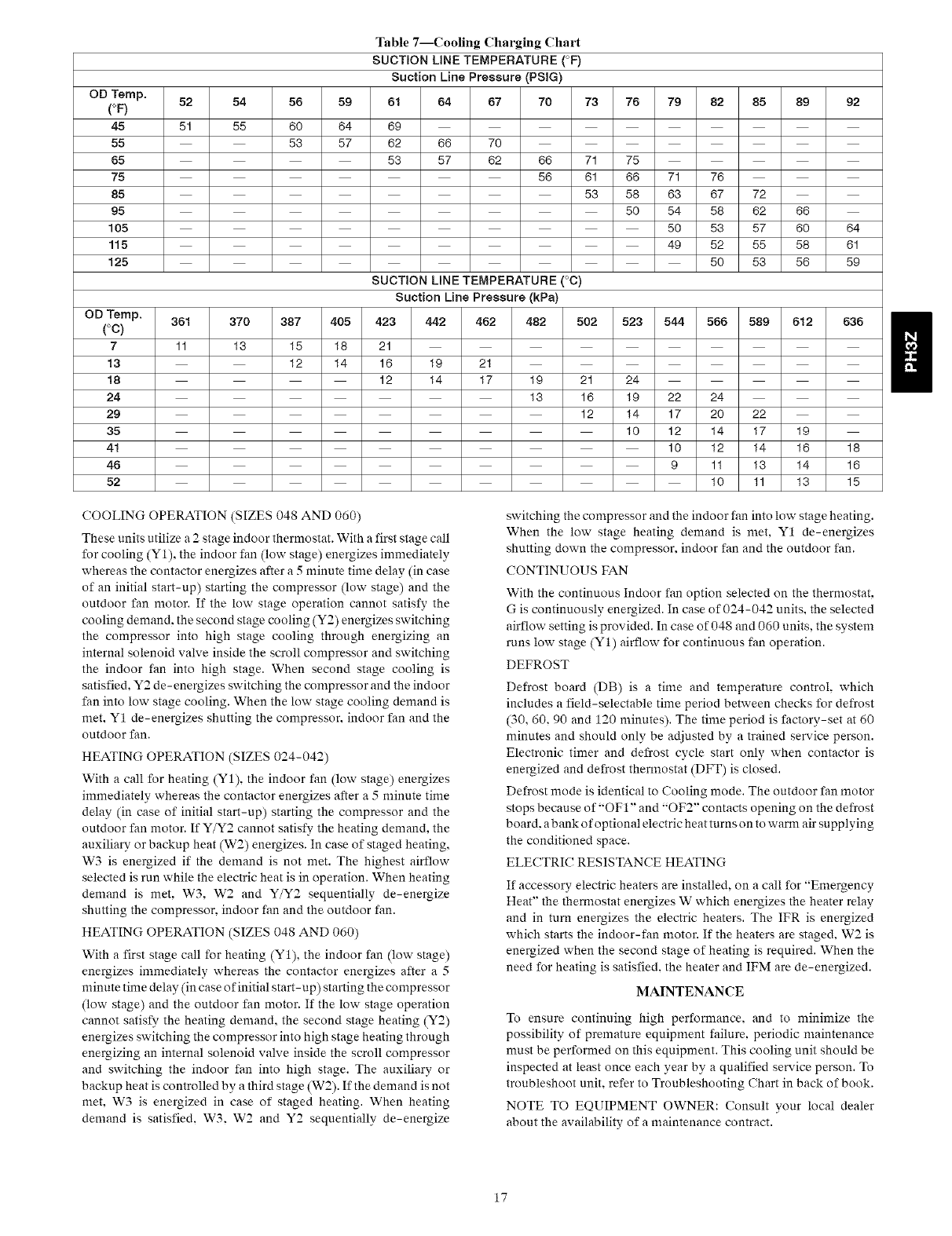
LOW CHARGE COOLING
024-042 units:
1. Measure suction line pressure by attaching a gauge to the
service port.
2. Measure the suction line temperature by attaching a
temperature sensing device to it.
3. Insulate the temperature sensing device so that the outdoor
ambient doesn't affect the reading.
4. Locate the measured suction line pressure in the top row of
Table 7 and the measured outdoor ambient temperature in
the left colunm of the table. Based on the two values,
determine the required suction line temperature.
5. If the measured suction line temperature is greater than the
tabulated temperature, add charge in the system.
048 and 060 units:
1. Measure discharge line pressure by attaching a gauge to the
service port.
2. Measure the liquid line temperature by attaching a
temperature sensing device to it.
3.Insulatethetemperaturesensingdevicesothattheoutdoor
ambientdoesn'taffectthereading.
4.RefertotherequiredsubcoolinginTables3and4tofindthe
requiredsubcoolingbasedonthenrodelsizeandtheoutdoor
ambienttemperature.
5.Interpolateif theoutdoortemperatureliesinbetweenthe
tablevalues.Extrapolateifthetemperatureliesbeyondthe
tablerange.
6.Findthepressurevaluecorrespondingtothemeasured
pressureonthecompressordischargeline.
7.Readacrossfromthepressurereadingtoobtaintheliquid
linetemperatureforarequiredsubcooling.
8.Addchargeif themeasuredtemperatureishigherthanthe
liquidlinetemperaturevalueinthetable.
9.Addchargeusingtheserviceconnectiononthesuctionline
ofthecompressor.
HEATINGMODECHARGE
Donotattempttoadjustchargebycoolingmethodswhileinheat
pumpheatingmode.Recoverrefrigerantandweighinaccordingto
unitdataplaterefrigerantdata.
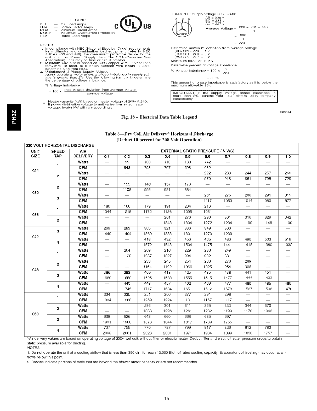
Step4--IndoorAirflowand Airflow Adjustments
NOTE: For cooling operation, the recommended airflow is 350 to
450 cfm for each 12,000 Btuh of rated cooling capacity.
Table 6 shows dry coil air delivery for horizontal discharge units.
Tables 8-10 show pressure drops.
NOTE: Be sure that all supply- and return-air grilles are open. free
from obstructions, and adjusted properly.
ELECTRICAL SHOCK HAZARD
Failure to follow this warning could result in personal injury
or death.
Disconnect electrical power to the unit and install lockout tag
before changing blower speed.
Airflow can be changed by changing the lead connections of the
blower motor.
All PH3Z blower motors are factory wired for rated airflow
operation.
FOR 208/230V BLOWER MOTORS
The motor lead speed connections are as follows:
SIZE RATED AIRFLOW HIGH AIRFLOW
024 Tap 1 Tap 3
030 Tap 2 Tap 4
036 Tap 1 Tap 3
042 Tap 2 Tap 4
RATED AIRFLOW HIGH AIRFLOW
SIZE Low High Low High
Stage Stage Stage Stage
048 Tap 1 Tap 3 Tap 2 Tap 4
060 Tap 1 Tap 3 Tap 2 Tap 4
Step 5--Unit Controls
All compressors have the following internal-protection controls.
HIGH-PRESSURE RELIEF VALVE
This valve opens when the pressure differential between the low and
high side becomes excessive.
LOSS OF CHARGE SWITCH
Located on the outdoor liquid line is a low-pressure switch which
functions as a loss-of-charge switch. This switch contains a
Schrader core depressor. This switch opens at 7 psig and closes at 22
psig. No adjustment is necessary.
COMPRESSOR OVERLOAD
This overload interrupts power to the compressor when either the
current or internal temperature become excessive, and
automatically resets when the internal temperature drops to a safe
level.
This overload may require up to 60 minutes (or longer) to reset:
therefore, if the internal overload is suspected of being open,
disconnect the electrical power to the unit and check the circuit
through the overload with an ohmmeter or continuity tester.
COMPRESSOR ROTATION
On 3-Phase units it is important to be certain compressor is rotating
in the proper direction. To determine whether or not compressor is
rotating in the proper direction:
1. Connect service gauges to suction and discharge pressure
fittings.
2. Energize the compressor.
3. The suction pressure should drop and the discharge pressure
should rise, as is normal on any start-up.
If the suction pressure does not drop and the discharge pressure does
not rise to normal levels:
1. Turn off power to the unit and tag disconnect.
2. Reverse any two of the unit power leads.
3. Turn on power to the unit.
The suction and discharge pressure levels should now move to their
normal start-up levels.
NOTE: When the compressor is rotating in the wrong direction, the
unit makes an elevated level of noise and does not provide cooling.
Step 6--Sequence of Operation
FAN OPERATION
The FAN switch on the thermostat controls indoor fan operation.
When the FAN switch is placed in the ON position, the IFR
(indoor-fan relay) is energized through the Gterminal on the
thermostat. The normally-open contacts close, which then provide
power to the indoor (evaporator) fan motor (IFM). The IFM will run
continuously when the FAN switch is set to ON.
When the FAN switch is set to AUTO, the thermostat deenergizes
the IFR (provided there is not a call for cooling). The contacts open
and the IFM is deenergized. The IFM will be energized only when
there is a call for cooling, in heat pump heating mode or if the unit
is equipped with accessory electric heat, the indoor-fan motor will
also run while the accessory electric heat is energized.
NOTE: Some units are equipped with a time-delay relay. On these
units, the indoor fan remains on for 30 seconds after G or Y is
deenergized.
COOLING OPERATION (SIZES 024-042)
With a call for cooling (Y/Y2), the indoor fan energizes immediately
whereas the contactor energizes after a 5 minute time delay (in case
of initial start-up) starting the compressor and the outdoor fan
motor. When the cooling demand is met. Y/Y2 de-energizes,
shutting the compressor, indoor fan and the outdoor fan.
H
F E_D SCHEMATIC
DNII ONIY
MAXIMUM WIRE
SIZE 2 A_G
SUPPLY ..... .........................] D{ @ D_ 2081230-3-60
po_,_ '_'_ ............<3_>'<_"1-_/ _:_>_<:_:_................................................"'_J-_ oM
......................................._'.........................._'_ i_EL \_'"_1 _
RED
DEEROST BOARD {DB)
R R
Y
0
c
I EGEND
UN]T COMPONENT ARRANGEMENT
OUTDOOR_AN CONTROLBOXAR_
M \ F3Et_SPNCZ
o T_R_]_ _Ut_ARKE_} PCAPACITOR
o SPLICE CC_ CR_ C_SE _AT_
O SPLICE _R_E_ CO_ COmPReSSOR_010_
......._AcroRYWIR}NG ClO CO_PR£SSORTIM[ DELAY
......FIZLD CONTROL_]RING @_ DZ}BOS_BOAR_
F]F:LDPO_F:R_IR_NG I)FT O_}ROS__HERMOSTAT
ACC}:SSORYOR OPT}ONAL DR D_FROST_ELAT
_]RjRG FC_ FAN CO_RO_ 50AR_
G_D GROURD
TO I_DICAI_ CO_ON _R _[AHR RE[A?
POI[_IAL O_#Ly
NOT_0 REPR[S(NIW!R[_G Z_ {NDOORFAN _OTOR
LO_ FBZSS_RES_]TCF_
NPS >HGNPRESSURES_ITCH
O_M OUTDOORFAN _010R
RVS REVERSINGVALVESOLENO]_
IRAN iRANS_OR_ER
IfA_Y OF TREORIGINA__RZS FUBO_EDARE RZ_AC[_ A_ QV C
F_:.......... /[OUlP _ _us__E REPLACZ__i_ _ypZ 90 DEGREEC _IRE OR .............
I S S_PPLIED _ _36=1
5 _[iOCATTO_IOF SP[[_ 7_PS MAY a[ REaU[R_9
24V SPLICE
_F_R_IS_ CORRECtsp_EpTAP S_INS
$_Do NOT_[SCONNECTP_UGUN_[RLOaD-
D P SWI1CH SE:1[(NGS
I I
CTD (TtT2] COMPRESSOR DELAY
CLOSES OP_S
TSA_
Fig. 12 -Typical Single-Phase Unit Electrical Diagram (Sizes 024-042)
A06404
i0
L_/ SCHEMATIC
SUPP Y 208/230+60
POW R
UNIT ONLY
MAN MUM W[R OM
SIZE 2 AWG Y_L
BL
COMP SOLENOID
TRAN!
I I)£FROST BOARD (DB)
/77
SEF NOTE #6
BUN
BIK
BtK
UNIT ¢OMPONEN} ARRANGEM[NI
O_TDOORFA#
s_cr;o_
[<!}
I_v!:3
COt_ROL BOX AREA
[i!i!:!!
........ COffTRO
@
FIELb
24V SPLICE 24y PO,_ER[_TRY
L_f][_D SFL]CE
¢I_CUI_ _EA_[R
_OU_
_OTTO R[?ESEN_ _I_I_6 IPS LO_ _ESSUR_ S_T¢_
HPS H_H _R{SSU_ES_HCH
RVS R[VE_SI_6 V_LV[ SOLENOID
1 iT AaYO_ TH[ORiGinAl _IR[S TURa_S_[__REffFPIA(ED fAN S£OUENC[ CTD {_1%2) COMPRESSOR_LAY
_ SE[ _IC£ ?_6[S ro_ _E_OSTAT _ S_88_SES _ _ _90 O_ '5 S£¢ '1¸ 1_ _
I 50ZH500314 IlO0
A0640
Fig. 13 - Typical Single-Phase Unit Electrical Diagram (Sizes 048-060)
D
11

H
P E_D SCHEMATIC
DNII ONIY
MAXIMUM WIRE
SIZE 2 A_G
SUPPLYpo_[_..... CCH ,VV<_ .........................] DR@ D 2081230-3-60
...... "_'_ ............<_J>_'<_"l-_/ _:_>_<°':_................................................"_J-_ oM
......................................_'.........................._'_ i_EL \_'"_1 )
...................._P_Y_ N BU ] ,_ OT I ) ..............._RN i_R _ilu_.........
II....................................................................................
EODIP GND
RED
DEPROST BOARD {DB)
R R
Y
O
I EGEND
UNIT COMPONENT ARRANGEF4ENT
OUTDOOR_A_ CONTROLBOX_,R_
/k F_EL_sPrEE
C_ _[R_NAL _R_ED} C CONT_CTOR
o T_R_]_ _Ut_RKE_} C_P C_P_CIrO_
o SPLICE CC_ CR_ C_SE _T_
......._AcroRYWIR}NG ClO CO_PR£SSORT[_[ DELAY
......FIELD CONTROL_]RING @_ DZ}BOS_BOAR_
FH:LD PO_F:RWIRING I)FT O_}ROS__HERMOSTAT
ACC}_SSORYOR OPT!ONAL DR D_ROST RELAY
G_D GROUND
TO I_DICAI_ CO_ON _R _[MER _[[A?
POI[_IAL O_#Ly
NOT_0 REPR_S_NIW!R[_G _ {NDOOR _OTOR
LO_ FBESSgRESW]TCF_
NPS }_iO_PRESSURES_ITCH
O_ OUTDOORFA_ _010R
RVS REVERSINGVALVESOLENOI_
]RAN IRANS_OR_ER
IfA_ OF THEORIGINA__RZS FUB_ED AR_ R[_AC[_ AR O_ C
F_:.......... _[QUIP
[] ..... ...........
I ............................l_"i"s_-o_cf"_ 3 USE 75_[GRKI COPPER COndUCTORSFORf[[l_ ;NSTAIIAT]ON G 6
I S S_PPLIED _36=1
_4V SPIICF
_F_IS_ CORRECtSP_EPTAP S_IN_
D P SWIICH SE f(NGS
I I
#
CTD (TtT2] COMPRESSOR DELAY
L_SEc_, ,.......
CLOSES OP_S
TSA_
Fig. 14 -Typical Three-Phase []nit Electrical Diagram (Sizes 030-042)
A06325
12
I)) SCHEMATIC
208/230-3-60
UN!T ONLY
MAN]MUM WIRE
S[Z[ 2 AW6 YEL
EONIPGND
FOR WIRING WITH
ELECTRIC HEAT['3RG J _'==_ J I
GE SCHEMATIC _T JjI
ON IIEATE_( ACCESSORy. J _ C _ I
I L'-'.- J) I
mS[ i _/i
J _ 1< Ii
r-_ = =-T->F7i i
•imJ ...................i i i
(lJ............_>J (..... i)
( ' ' ......... C>) _ ( i)
[](m_ ( i)
(ii.............C_ r -
IL1
6 ...........GRN...............
R ........................RED
Y! .......................TEL ....................
0 ORN
W2 .......................WNT ..........
Y2 .................PNN ...........
ws V]O .......
C BR
p':
EE:::}
UNIT COMPONENT ARRANGEMENT
_+_E_ _SI_G rlELD I_S_LLED [L_C;R_C _[AT_S
CONSGLr _S%ALLAIIO_ ]_STRSCT]ONS TO
_E%ERM[N{ CORRECT SPIED TAP $_:I11NG
2_v POW{R ENIRy 5 "DO _OT a)SCON_ECT ?t_G U_gER _O_D "
C_ (]_]2} COmpRESSORD{LAY
A06326
Fig. 15 -Typical Three-Phase Unit Electrical Diagram (Sizes 048-060)
D
13
CONTROL P I JC
BOARD _ _
STEP 1 W_T ...............
v;o
TO
ill RELAY1
i I_ •8RN _ AUTO LIMIT
I ii RELAY 2 I |
1 BRN • EL2 AUTO LINIT _J
_41 1BLN_YEL
• _ _ _L ,O,OLt_IT
I 3
i _BLK YEL-_
, !
I
IRELAY 4
-- BRN_] EL4 AUTO LIMIT
BLK "_ YEL
Fig. 16 -Single-Phase Accessory Electric Heater Wiring
PINK
?W3 VIOLET
TO #N fCO_fROL /I
WI_XNG 24VAC _ MR3
'1
BLACK BLAC]_
_It YELLOW
Jt
Et_ AUTO-LINIT BLUE
_,vvvvvv'_
EL3 AUTO.LINIT BLACN
TO UNIT POWER
WIRING
CB_ I
]
]L1
L2
L3
Fig. 17 -Three-Phase Accessory Electric Heater Wiring
A05209
A06327
14
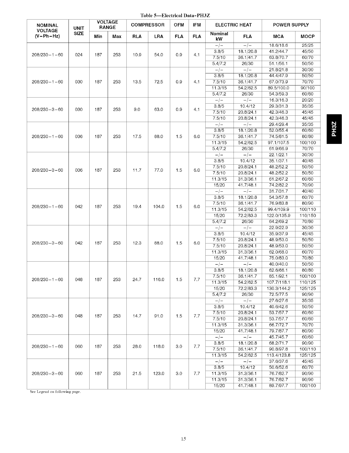
Table 5--Electrical Data-PH3Z
VOLTAGE
RANGE
NOMINAL UNIT
VOLTAGE SIZE
(V-Ph-Hz) Min Max
208/230-1 - 60 024 187 253
208/230-1 - 60 030 187 253
208/230- 3- 60 030 187 253
208/230-1 - 60 036 187 253
208/230- 3- 60 036 187 253
208/230-1 - 60 042 187 253
208/230- 3- 60 042 187 253
208/230-1 - 60 048 187 253
208/230- 3- 60 048 187 253
208/230-1 - 60 060 187 253
208/230- 3- 60 060 187 253
See Legend on following page.
COMPRESSOR OFM IFM ELECTRIC HEAT
Nominal
RLA LRA FLA FLA kW
--/--
3.6/5
lO.9 54.0 0.9 4.1 7.5/lO
5.4/7.2
--/--
3.6/5
13.5 72.5 0.9 4.1 7.5/lO
11.3/15
5.4/7.2
--/--
3.6/5
9.0 63.0 0.9 4.1 7.5/1o
7.5/lO
--/--
3.6/5
17.5 88.0 1.5 6.0 7.5/1o
11.3/15
5.4/7.2
--/--
3.6/5
7.5/lO
11.7 77.0 1.5 6.0 7.5/1o
11.3/15
15/2o
--/--
3.6/5
7.5/lO
19.4 lO4.O 1.5 6.0 11.3/15
15/2o
5.4/7.2
--/--
3.6/5
7.5/1o
12.3 88.0 1.5 6.0 7.5/1o
11.3/15
15/2o
--/--
3.6/5
7.5/1o
24.7 116.o 1.5 7.7 11.3/15
15/2o
5.4/7.2
--/--
3.6/5
7.5/1o
14.7 91.o 1.5 7.7 7.5/1o
11.3/15
15/2o
--/--
3.6/5
28.0 118.o 3.0 7.7 7.5/1o
11.3/15
--/--
3.6/5
21.5 123.o 3.0 7.7 11.3/15
11.3/15
15/2o
FLA
-/-
18.1/20.8
36.1/41.7
26/30
--/--
18.1/20.8
36.1/41.7
54.2/62.5
26/30
--/--
10.4/12
20.8/24.1
20.8/24.1
--/--
18.1/20.8
36.1/41.7
54.2/62.5
26/30
--/--
10.4/12
20.8/24.1
20.8/24.1
31.3/36.1
41.7/48.1
--/--
18.1/20.8
36.1/41.7
54.2/62.5
72.2/83.3
26/30
--/--
10.4/12
20.8/24.1
20.8/24.1
31.3/36.1
41.7/48.1
--/--
18.1/20.8
36.1/41.7
54.2/62.5
72.2/83.3
26/30
--/--
10.4/12
20.8/24.1
20.8/24.1
31.3/36.1
41.7/48.1
--/--
18.1/20.8
36.1/41.7
54.2/62.5
--/--
10.4/12
31.3/36.1
31.3/36.1
41.7/48.1
POWER SUPPLY
MCA MOCP
18.6/16.6 25/25
41.2/44.7 45/50
63.8/70.7 60/70
51.1/56.1 50/50
21.6/21.8 30/30
44.4/47.9 50/50
67.0/73.9 70/70
69.5/100.0 90/100
54.3/59.3 60/60
16.3/16.3 20/20
29.3/31.3 35/35
42.3/46.3 45/45
42.3/46.3 45/45
29.4/29.4 35/35
52.0/55.4 60/60
74.5/61.5 80/60
97.1/107.5 100/100
61.9/66.9 70/70
22.1/22.1 30/30
35.1/37.1 40/45
48.2/52.2 50/50
48.2/52.2 50/50
61.2/67.2 60/60
74.2/82.2 70/90
31.7/31.7 40/40
54.3/57.8 60/70
76.9/83.8 80/90
99.4/109.9 100/110
122.0/135.9 110/150
64.2/69.2 70/80
22.9/22.9 30/30
35.9/37.9 45/45
48.9/53.0 50/50
48.9/53.0 50/50
62.0/68.0 60/70
75.0/83.0 70/80
40.0/40.0 50/50
62.6/66.1 80/80
85.1/92.1 100/100
107.7/118.1 110/125
130.3/144.2 125/125
72.5/77.5 90/90
27.6/27.6 35/35
40.6/42.6 50/50
53.7/57.7 60/60
53.7/57.7 60/60
66.7/72.7 70/70
79.7/87.7 80/90
45.7/45.7 60/60
68.2/71.7 90/90
90.8/97.8 100/110
113.4/123.8 125/125
37.6/37.6 45/45
50.6/52.6 60/70
76.7/82.7 90/90
76.7/82.7 90/90
89.7/97.7 100/100
15
LEGEND @
FLA Full Load Amps
LRA Locked Rotor An/ps C US
MOA -- Minimum Circuit An/ps
MOCP Maxin/un/ Overcurrent Protection
RLA Rated Load An/ps
NOTES:
1. In compliance with NEO (National Electrical Code) requirements
for multht/otor and combination load equipment (refer to NEC
Articles 430 and 440), the overcurrent protective device for the
unit shall be Power Supply fuse. The CGA (Canadian Gas
Association) units may be fuse or circuit breakel:
2. Minimum wire size is based on 60°0 copper wire. If other than
60°0 wire is used, or if length exceeds wire length in table,
determine size from NEC.
3. Unbalanced 3-Phase Supply Voltage
Never oper>_te a motor wher_ a phase irnbaF_nce in supply volt-
age is greater than 2%. Use the following formula to determine
the percentage of voltage imbalance.
% Voltage imbalance
100 x max voltage deviation from average voltage
average voltage
.Heater capacity (kW) based on heater voltage of 208v & 240v.
If power distribution voltage to unit varies from rated heater
voltage, heater kW will vary accordingly.
EXAMPLE: Supply voltage is 230-3-60.
AB = 228 v
BG = 231 v
AO = 227 v
Average Voltage = 228 + 231 + 227
3
=68___£6
3
229
Determine n/aximun/ deviation from average voltage.
(AB) 229 - 228 1 v
(BO) 231 - 229 2 v
(AO) 229 -227 2 v
Maxin/un/ deviation is 2 v.
Determine percent of voltage imbalance.
2
% Voltage Imbalance 100 x --
229
0.6%
This amount of phase imbalance is satisfactory as it is below the
maxin/un/ allowable 2%.
IMPORTANT: If the supply local electdo utility company
voltage phase imbalance is
more than 2%, contact your
in/mediately.
Fig. 18 - Electrical Data Table Legend
008014
Table 6--Dlw Coil Air Delivery" Horizontal Discharge
(Deduct 10 percent for 208 Volt Operation)
230 VOLT HORIZONTAL DISCHARGE
UNIT SPEED AIR EXTERNAL STATIC PRESSURE (IN.WG)
SIZE TAP DELIVERY 0,1 0.2 0.3 0,4 0,5 0.6 0,7 0,8 0.9 1,0
Watts 99 1O0 118 130 142
1CFM 848 793 757 698 632
024 Watts 222 233 244 257 260
2CFM 970 918 861 795 729
Watts 155 146 157 170
2CFM 1108 995 951 884
030 Watts 261 275 286 291 315
3CFM 1117 1053 1014 980 877
Watts 180 166 179 191 204 216
1CFM 1344 1215 1172 1136 1095 1051
036 Watts 261 276 290 301 316 329 342
2CFM 1343 1304 1272 1234 1190 1148 1100
Watts 269 283 305 321 336 349 360
3CFM 1440 1404 1369 1333 1301 1273 1239
042 Watts 418 432 450 465 480 490 503 518
4CFM 1572 1543 1504 1475 1441 1418 1380 1332
Watts 204 209 216 229 236 249
1CFM 1129 1087 1027 994 932 881
Watts 233 245 254 266 276 289
2CFM 1164 1122 1066 1025 954 906
048 Watts 386 398 409 418 425 435 438 441 451
3CFM 1680 1652 1625 1583 1555 1515 1477 1444 1403
Watts 440 448 457 462 469 477 480 485 486
4CFM 1745 1717 1684 1651 1612 1573 1537 1508 1470
Watts 224 235 251 266 277 291 298
1CFM 1334 1288 1259 1224 1181 1157 1117
Watts 286 301 311 325 333 344 370
2CFM 1333 1296 1261 1232 1199 1170 1062
060 Watts 608 626 643 660 668 685 697
3CFM 1931 1900 1878 1844 1817 1789 1755
Watts 737 755 770 787 799 817 826 812 782
4CFM 2093 2061 2028 2001 1971 1934 1899 1850 1757
*Air delivery values are based on operating voltage of 230v, wet coit, without filter or electric heater. Deduct filter and electric heater pressure drops to obtain
static pressure available for ducting.
NOTES:
1. Do not operate the unit at a cooling airflow that is less than 350 cfm for each 12,000 Btuh of rated cooling capacity. Evaporator coil frosting may occur at air-
flows below this point.
2. Dashes indicate portions of table that are beyond the blower motor capacity or are not recommended.
ld
ODTemp. 52
(°F)
45 51
55
65
75
85
95
105
115
125
54 56 59
55 60 64 69
53 57 62 66
53 57
Table 7--Cooling Charging Chart
SUCTION LINE TEMPERATURE (°F)
Suction Line Pressure (PSIG)
61 64 67 70 73 76 79 82 85 89 92
70
62 66 71 75
56 61 66 71 76
53 58 63 67 72
50 54 58 62 66
50 53 57 60 64
49 52 55 58 61
50 53 56 59
SUCTION LINE TEMPERATURE (°C)
Suction Line Pressure (kPa)
OD Temp.
(°C) 361 370 387 405 423 442 462 482 502 523 544 566 589 612 636
7 11 13 15 18 21
13 12 14 16 19 21
18 12 14 17 19 21 24
24 13 16 19 22 24
29 12 14 17 20 22
35 10 12 14 17 19
41 10 12 14 16 18
46 9 11 13 14 16
52 10 11 13 15
COOLING OPERATION (SIZES 048 AND 060)
These units utilize a 2 stage indoor thermostat. With a first stage call
for cooling (Y1), the indoor fan (low stage) energizes immediately
whereas the contactor energizes after a 5 minute time delay (in case
of an initial start-up) starting the compressor (low stage) and the
outdoor fan motor. If the low stage operation cannot satisfy the
cooling demand, the second stage cooling (Y2) energizes switching
the compressor into high stage cooling through energizing an
internal solenoid valve inside the scroll compressor and switching
the indoor fan into high stage. When second stage cooling is
satisfied, Y2 de-energizes switching the compressor and the indoor
fan into low stage cooling. When the low stage cooling demand is
met, Y1 de-energizes shutting the compressor, indoor fan and the
outdoor fan.
HEATING OPERATION (SIZES 024-042)
With a call for heating (Y1), the indoor fan (low stage) energizes
immediately whereas the contactor energizes after a 5 minute time
delay (in case of initial start-up) starting the compressor and the
outdoor fan motor. If Y/Y2 cannot satisfy the heating demand, the
auxiliary or backup heat (W2) energizes. In case of staged heating,
W3 is energized if the demand is not met. The highest airflow
selected is run while the electric heat is in operation. When heating
demand is met. W3. W2 and Y/Y2 sequentially de-energize
shutting the compressor, indoor fan and the outdoor fan.
HEATING OPERATION (SIZES 048 AND 060)
With a first stage call for heating (Y1), the indoor fan (low stage)
energizes immediately whereas the contactor energizes after a 5
minute time delay (in case of initial start-up) starting the compressor
(low stage) and the outdoor fan motor. If the low stage operation
cannot satisfy the heating demand, the second stage heating (Y2)
energizes switching the compressor into high stage heating through
energizing an internal solenoid valve inside the scroll compressor
and switching the indoor fan into high stage. The auxiliary or
backup heat is controlled by a third stage (W2). If the demand is not
met, W3 is energized in case of staged heating. When heating
demand is satisfied, W3, W2 and Y2 sequentially de-energize
switching the compressor and the indoor fan into low stage heating.
When the low stage heating demand is met, Y1 de-energizes
shutting down the compressor, indoor fan and the outdoor fan.
CONTINUOUS FAN
With the continuous Indoor fan option selected on the thermostat.
G is continuously energized. In case of 024-042 units, the selected
airflow setting is provided. In case of 048 and 060 units, the system
runs low stage (Y1) airflow for continuous fan operation.
DEFROST
Defrost board (DB) is a time and temperature control, which
includes a field-selectable time period between checks for defrost
(30, 60, 90 and 120 minutes). The time period is factory-set at 60
minutes and should only be adjusted by a trained service person.
Electronic timer and defrost cycle start only when contactor is
energized and defrost thermostat (DFT) is closed.
Defrost mode is identical to Cooling mode. The outdoor fan motor
stops because of "OF1" and "OF2" contacts opening on the defrost
board, abank of optional electric heat turns on to warm air supplying
the conditioned space.
ELECTRIC RESISTANCE HEATING
If accessory electric heaters are installed, on a call for "Emergency
Heat" the thermostat energizes W which energizes the heater relay
and in turn energizes the electric heaters. The IFR is energized
which starts the indoor-fan motor. If the heaters are staged, W2 is
energized when the second stage of heating is required. When the
need for heating is satisfied, the heater and IFM are de-energized.
MAINTENANCE
To ensure continuing high performance, and to minimize the
possibility of premature equipment failure, periodic maintenance
must be performed on this equipment. This cooling unit should be
inspected at least once each year by a qualified service person. To
troubleshoot unit, refer to Troubleshooting Chart in back of book.
NOTE TO EQUIPMENT OWNER: Consult your local dealer
about the availability of a maintenance contract.
17
PERSONALINJURYANDUNITDAMAGE HAZARD
Failure to follow this warning could result in personal injury
or death and possible unit component damage.
The ability to properly perform maintenance on this
equipment requires certain expertise, mechanical skills, tools
and equipment. If you do not possess these, do not attempt to
perform any maintenance on this equipment, other than those
procedures recommended in the Owner's Manual.
The minimum maintenance requirements for this equipment are as
follows:
1. Inspect air filter(s) each month. Clean or replace when
necessary.
2. Inspect indoor coil, drain pan, and condensate drain each
cooling season for cleanliness. (;lean when necessary.
3. Inspect blower motor and wheel for cleanliness each cooling
season. (;lean when necessary.
4. Check electrical connections for tightness and controls for
proper operation each cooling season. Service when
necessary.
5. Ensure electric wires are not in contact with refrigerant
tubing or sharp metal edges.
ELECTRICAL SHOCK HAZARD
Failure to follow these warnings could result in personal
injury or death:
1. Turn off electrical power to the unit before performing any
maintenance or service on this unit.
2. Use extreme caution when removing panels and parts.
3. Never place anything combustible either on or in contact
with the unit.
Step 1--Air Filter
IMPORTANT: Never operate the unit without a suitable air filter
in the return- air duct system. Always replace the filter with the same
dimensional size and type as originally installed. See Table 1 for
recommended filter sizes.
Inspect air filter(s) at least once each month and replace
(throwaway-type) or clean (cleanable-type) at least twice during
each cooling season and twice during the heating season, or
whenever the filter becomes clogged with dust and lint.
Step 2--Unit Top Removal (Outdoor-Coil Side)
NOTE: When performing maintenance or service procedures that
require removal of the unit top, be sure to perform all of the routine
maintenance procedures that require top removal, including coil
inspection and cleaning, and condensate drain pan inspection and
cleaning.
ELECTRICAL SHOCK HAZARD
Failure to fnllow this warning could result in personal injury
or death.
Disconnect and tag electrical power to the unit before
removing top.
Only qualified service personnel should perform maintenance and
service procedures that require unit top removal.
Refer to the fnllowing top removal procedures:
18
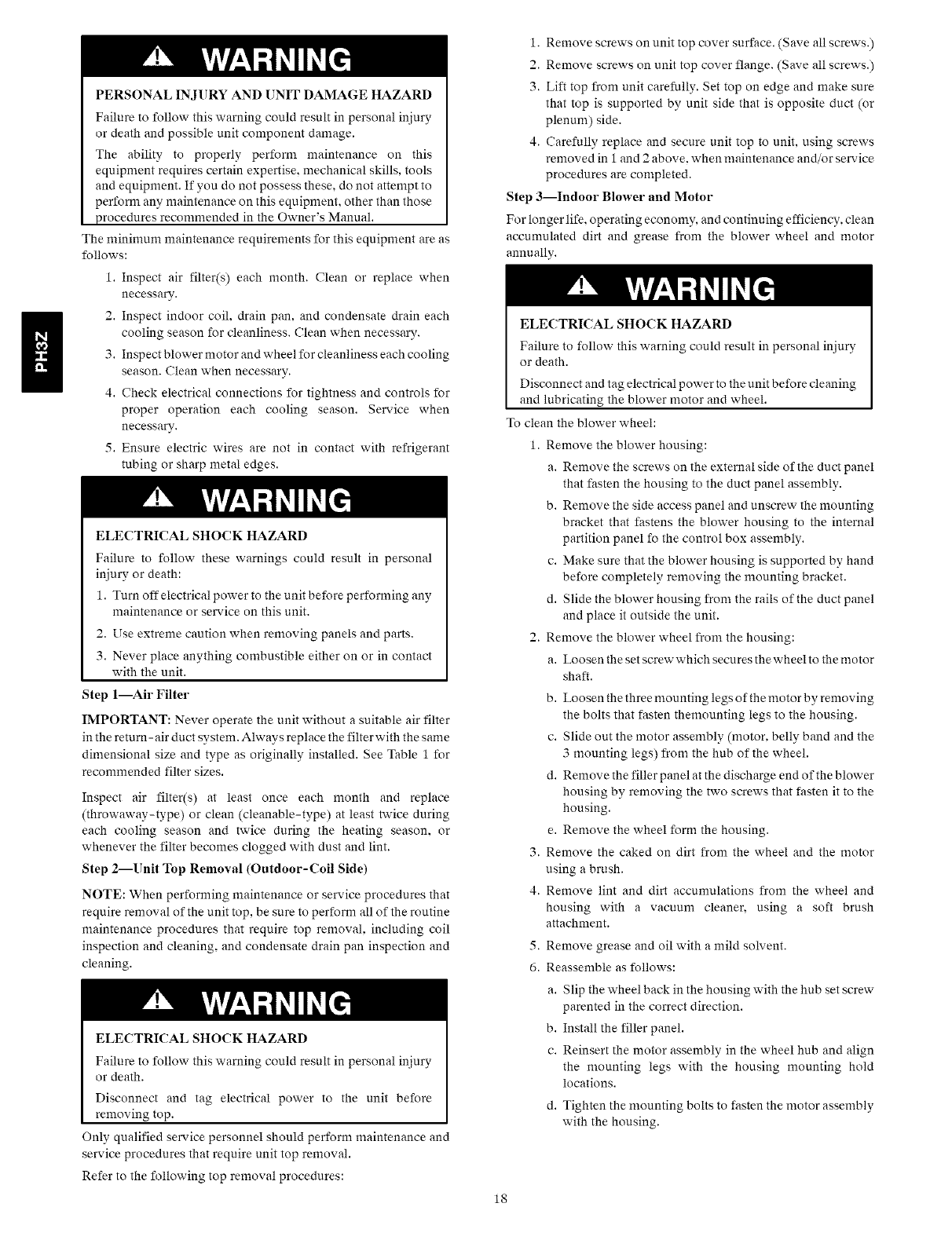
i. Remove screws on unit top cover surface. (Save all screws.)
2. Remove screws on unit top cover flange. (Save all screws.)
3. Lift top from unit carefully. Set top on edge and make sure
that top is supported by unit side that is opposite duct (or
plenum) side.
4. Carefully replace and secure unit top to unit, using screws
removed in 1 and 2 above, when maintenance and/or service
procedures are completed.
Step 3--Indoor Blower and Motor
For longer life, operating economy, and continuing efficiency, clean
accumulated dirt and grease from the blower wheel and motor
annually.
ELECTRICAL SHOCK HAZARD
Failure to follow this warning could result in personal injury
or death.
Disconnect and tag electrical power to the unit before cleaning
and lubricating the blower motor and wheel.
To clean the blower wheel:
1. Remove the blower housing:
a. Remove the screws on the external side of the duct panel
that fasten the housing to the duct panel assembly.
b. Remove the side access panel and unscrew the mounting
bracket that fastens the blower housing to the internal
partition panel fo the control box assembly.
c. Make sure that the blower housing is supported by hand
before completely removing the mounting bracket.
d. Slide the blower housing from the rails of the duct panel
and place it outside the unit.
2. Remove the blower wheel from the housing:
a. Loosen the set screw which secures the wheel to the motor
shaft.
b. Loosen the three mounting legs of the motor by removing
the bolts that fasten themounting legs to the housing.
c. Slide out the motor assembly (motor. belly band and the
3 mounting legs) from the hub of the wheel.
d. Remove the filler panel at the discharge end of the blower
housing by removing the two screws that fasten it to the
housing.
e. Remove the wheel form the housing.
3. Remove the caked on dirt from the wheel and the motor
using a brush.
4. Remove lint and dirt accumulations from the wheel and
housing with a vacuunr cleaner, using a soft brush
attachment.
5. Remove grease and oil with a mild solvent.
6. Reassemble as follows:
a. Slip the wheel back in the housing with the hub set screw
parented in the correct direction.
b. Install the filler panel.
c. Reinsert the motor assembly in the wheel hub and align
the mounting legs with the housing mounting hold
locations.
d. Tighten the mounting bolts to fasten the motor assembly
with the housing.
UNIT
SIZE
024
030
036
042
048
060
6O0
.027
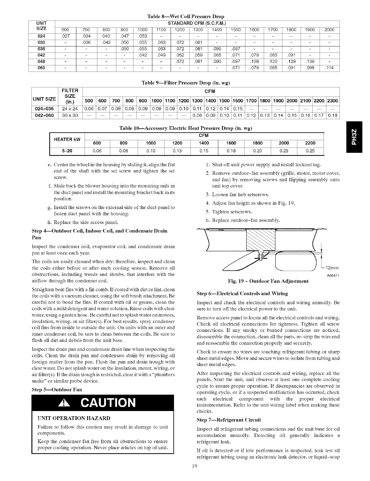
Table 8--Wet Coil Pressure Drop
STANDARD CFM (S.C.F.M.)
700 800 900 1000 1100 1200 1300 1400 1500 1600 1700 1800 1900 2000
.034 040 .047 .053
.036 .042 .050 .055 .063 .072 .081
-.050 .055 .063 .072 .081 .090 .097
- .042 .049 .052 .059 .065 .071 .078 .085 .091
- .072 .081 .090 .097 .108 .120 .129 .139
- .071 .078 .085 .091 .098 .114
UNIT SIZE
024-036
042-060
Table 9--Filter Pressure Drop (in. wg)
FILTER CFM
SIZE
(in.) 500 600 700 800 900 1000 1100 1200 1300 1400 1500 1600 1700 1800 1900 2000 2100 2200 2300
24x24 0.06 0.07 0.08 0.08 0.09 0.09 0.09 0.10 0.11 0.12 0.14 0.15
30x30 0.08 0.09 0.10 0.11 0.12 0.13 0.14 0.15 0.16 0.17 0.18
Table 10---Accessory Electric Heat Pressure Drop (in. wg)
CFM
HEATER kW 600 800 1000 1200 1400 1600 1800 2000 2200
5-20 0.06 0.08 0.10 0.13 0.15 0.18 0.20 0.23 0.25
e. (;enter the wheel in the housing by sliding it, align the flat
end of the shaft with the set screw and tighten the set
screw.
f. Slide back the blower housing into the mounting rails in
the duct panel and install the mounting bracket back in its
position.
g. Install the screws on the external side of the duct panel to
fasten duct panel with the housing.
h. Replace the side access panel.
Step 4--Outdoor Coil, Indoor Coil, and Condensate Drain
Pan
Inspect the condenser coil. evaporator coil and condensate drain
pan at least once each year.
The coils are easily cleaned when dry; therefore, inspect and clean
the coils either before or after each cooling season. Remove all
obstructions, including weeds and shrubs, that interfere with the
airflow through the condenser coil.
Straighten bent fins with afin comb. If coated with dirt or lint, clean
the coils with avacuum cleaner, using the soft brush attachment. Be
careful not to bend the fins. If coated with oil or grease, clean the
coils with amild detergent and water solution. Rinse coils with clear
water, using a garden hose. Be careful not to splash water on motors,
insulation, wiring, or air filter(s). For best results, spray condenser
coil fins from inside to outside the unit. On units with an outer and
inner condenser coil, be sure to clean between the coils. Be sure to
flush all dirt and debris from the unit base.
Inspect the drain pan and condensate drain line when inspecting the
coils. Clean the drain pan and condensate drain by removing all
foreign matter from the pan. Flush the pan and drain trough with
clear water. Do not splash water on the insulation, motor, wiring, or
air filter(s). If the drain trough is restricted, clear it with a "plumbers
snake" or similar probe device.
Step 5--Outdoor Fan
UNIT OPERATION HAZARD
Failure to follow this caution may result in damage to unit
components.
Keep the condenser fan free from all obstructions to ensure
proper cooling operation. Never place articles on top of unit.
i. Shut off unit power supply and install lockout tag.
2. Remove outdoor-fan assembly (grille, motor, motor cover,
and fan) by removing screws and flipping assembly onto
unit top cover.
3. Loosen fan hub setscrews.
4. Adjust fan height as shown in Fig. 19.
5. Tighten setscrews.
6. Replace outdoor-fan assembly.
12mm
A06411
Fig. 19 - Outdoor Fan Adjustment
Step 6--Electrical Controls and Wiring
Inspect and check the electrical controls and wiring annually. Be
sure to turn off the electrical power to the unit.
Remove access panel to locate all the electrical controls and wiring.
Check all electrical connections for tightness. Tighten all screw
connections. If any smoky or burned connections are noticed,
disassemble the connection, clean all the parts, re-strip the wire end
and reassemble the connection properly and securely.
Check to ensure no wires are touching refrigerant tubing or sharp
sheet metal edges. Move and secure wires to isolate from tubing and
sheet metal edges.
After inspecting the electrical controls and wiring, replace all the
panels. Start the unit, and observe at least one complete cooling
cycle to ensure proper operation. If discrepancies are observed in
operating cycle, or if a suspected malfunction has occurred, check
each electrical component with the proper electrical
instrumentation. Refer to the unit wiring label when making these
checks.
Step 7--Refrigerant Circuit
Inspect all refrigerant tubing connections and the unit base for oil
accumulation annually. Detecting oil generally indicates a
refrigerant leak.
If oil is detected or if low performance is suspected, leak test all
refrigerant tubing using an electronic leak detector, or liquid-soap
19
solution.If a refrigerantleakis detected,referto Checkfor
RefrigerantLeakssection.
Ifnorefrigerantleaksarefoundandlowperformanceissuspected,
refertoCheckingandAdjustingRefrigerantChargesection.
Step8--IndoorAirflow
Theheatingand/orcoolingairflowdoesnotrequirecheckingunless
improperperformanceissuspected.Ifaproblemexists,besurethat
all supply-andreturn-airgrillesareopenandfreefrom
obstructions,andthattheairfilterisclean.
Step 9--Metering Devices
Refrigerant cooling metering device is an AccuRater (024-042) or
TXV (048 and 060) located upstream of the indoor coil distributor
assembly. Refrigerant heating mode metering device is an
AccuRater located upstrem of the outdoor coil distributor assembly.
Step lO--Liquid Line Strainers
The liquid line strainers (to protect metering devices) are made of
wire mesh and are located in the liquid lines on the inlet side of the
metering devices.
Step ll--High Flow Valves
High flow valves are located on the compressor hot gas and suction
tubes. Large black plastic caps distinguish these valves with
O - rings located inside the caps. These valves can not be accessed for
service in the field. Ensure the plastic caps are in place and tight or
the possibility of refrigerant leakage could occur.
TROUBLESHOOTING
Refer to the Troubleshooting (;hart (Table 11) for troubleshooting
information.
START-UP CHECKLIST
Use the Start-Up Checklist at the back of this manual.
2O
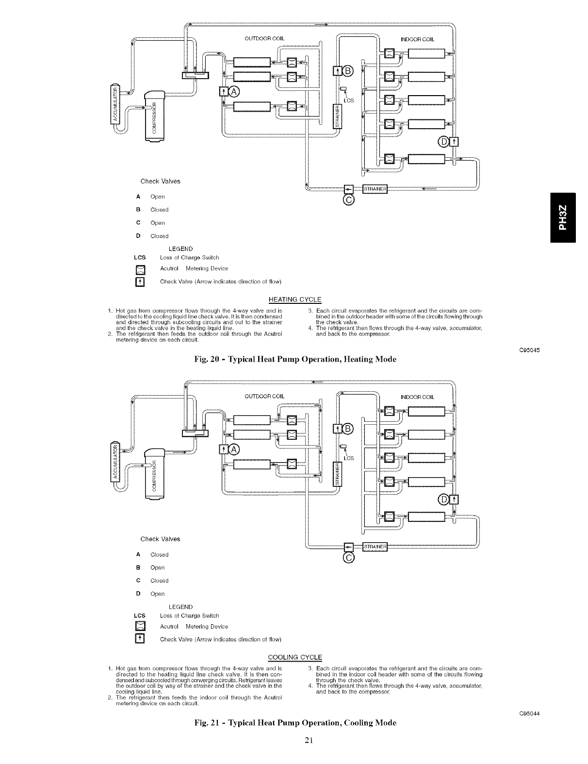
OUTDOOR COIL _ -- INDOOR COIL
Check Valves _ h
A Open
B Ck)sed
C Open
D Ck)sed
LEGEND
LCS Loss of Charge Switch
] Acutrol Metering Device
r_ Check Valve indicates direction of
(Arrow fk)w)
HEATING CYCLE
1. Hot gas from compressor flows through the 4-way valve and is
directed to the cooling liquid line check valve. It is then condensed
and directed through subcooling circuits and out to the strainer
and the check valve in the heating liquid line.
2. The refrigerant then feeds the outdoor coil through the Acutrol
metering device on each circuit.
3. Each circuit evaporates the refrigerant and the circuits are com-
bined in the outdoor header with some of the circuits flowing through
the check valve.
4. The refrigerant then flows through the 4-way valve, accumulator,
and back to the compressor.
Fig. 20 -Typical Heat Pump Operation, Heating Mode
C95045
Check Valves
OUTDOOR COIL
A Closed
B Open
C Ck)sed
D Open
LEGEND
LCS Loss of Charge Switch
] Acutrol Metering Device
] Check Valve (Arrow indicates direction of flow)
COOLING CYCLE
1. Hot gas from compressor flows through the 4-way valve and is
directed to the heating liquid line check valve. It is then con-
densed and subcooled th rough converging circuits. Refrigerant leaves
the outdoor coil by way of the strainer and the check valve in the
cooling liquid line.
2. The refrigerant then feeds the indoor coil through the Acutrol
metering device on each circuit.
3. Each circuit evaporates the refrigerant and the circuits are com-
bined in the indoor coil header with some of the circuits flowing
through the check valve.
4. The refrigerant then flows through the 4-way valve, accumulator,
and back to the compressor.
Fig. 21 - Typical Heat Pump Operation, Cooling Mode
C95044
21
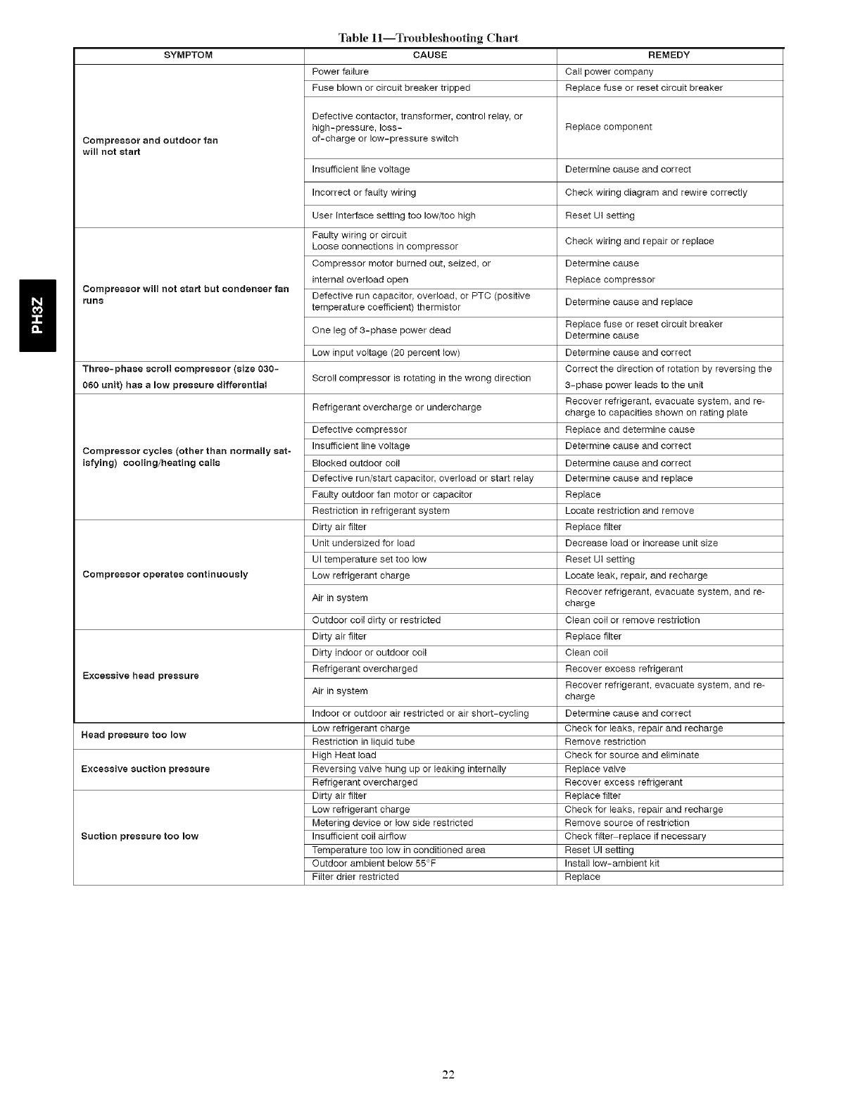
SYMPTOM
Compressor and outdoor fan
will not start
Compressor will not start but condenser fan
runs
Three=phase scroll compressor (size 030-
060 unit) has a low pressure differential
Compressor cycles (other than normally sat-
isfying) cooling/heating calls
Compressor operates continuously
Excessive head pressure
Head pressure tOO low
Excessive suction pressure
Suction pressure too low
Table ll--Troubleshooting Chart
CAUSE
Power failure
Fuse blown or circuit breaker tripped
REMEDY
Call power company
Replace fuse or reset circuit breaker
Defective contactor, transformer, control relay, or
high-pressure, loss- Replace component
of-charge or low-pressure switch
Determine cause end correct
Check wiring diagram and rewire correctly
Reset UI setting
Insufficient line voltage
Incorrect or faulty wiring
User Interface setting too low/too high
Faulty wiring or circuit
Loose connections in compressor
Compressor motor burned out, seized, or
internal overload open
Defective run capacitor, overload, or PTC (positive
temperature coefficient) thermistor
One leg of 3-phase power dead
Low input voltage (20 percent low)
Scroll compressor is rotating in the wrong direction
Refrigerant overcharge or undercharge
Defective compressor
Insufficient line voltage
Blocked outdoor coil
Defective run/start capacitor, overload or start relay
Faulty outdoor fan motor or capacitor
Restriction in refrigerant system
Dirty air filter
Unit undersized for load
UI temperature set too low
Low refrigerant charge
Air in system
Outdoor coil dirty or restricted
Dirty air filter
Dirty indoor or outdoor coil
Refrigerant overcharged
Air in system
Indoor or outdoor air restricted or air short-cycling
Low refrigerant charge
Restriction in liquid tube
High Heat load
Reversing valve hung up or leaking internally
Refrigerant overcharged
Dirty air filter
Low refrigerant charge
Metering device or low side restricted
Insufficient coil airflow
Temperature too low in conditioned area
Outdoor ambient below 55°F
Filter drier restricted
Check wiring end repair or replace
Determine cause
Replace compressor
Determine cause end replace
Replace fuse or reset circuit breaker
Determine cause
Determine cause end correct
Correct the direction of rotation by reversing the
3-phase power leads to the unit
Recover refrigerant, evacuate system, and re-
charge to capacities shown on rating plate
Replace and determine cause
Determine cause end correct
Determine cause end correct
Determine cause end replace
Replace
Locate restriction and remove
Replace filter
Decrease load or increase unit size
Reset UI setting
Locate leak, repair, end recharge
Recover refrigerant, evacuate system, and re-
charge
Clean coil or remove restriction
Replace filter
Clean coil
Recover excess refrigerant
Recover refrigerant, evacuate system, and re-
charge
Determine cause end correct
Check for leaks, repair and recharge
Remove restriction
Check for source end eliminate
Replace valve
Recover excess refrigerant
Replace filter
Check for leaks, repair and recharge
Remove source of restriction
Check filtemreplace if necessary
Reset UI setting
Install low-ambient kit
Replace
22
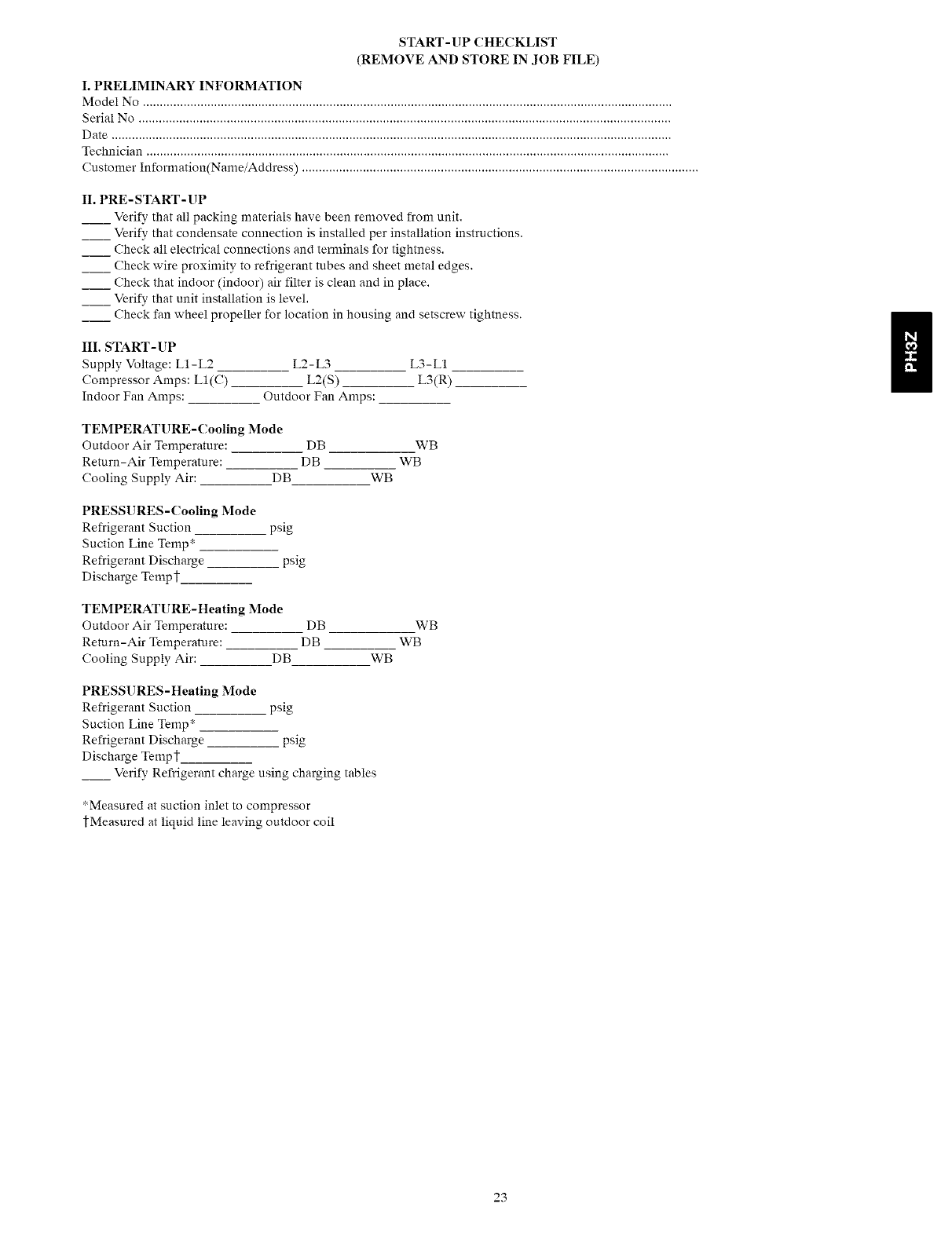
START-UP CHECKLIST
(REMOVE AND STORE IN JOB FILE)
I. PRELIMINARY INFORMATION
Model No ............................................................................................................................................................
Serial No .............................................................................................................................................................
Date .....................................................................................................................................................................
Technician ..........................................................................................................................................................
Customer Information(Name/Address) .....................................................................................................................
II. PRE-START-UP
__ Verify that all packing materials have been removed from unit.
__ Verify that condensate connection is installed per installation instructions.
__ Check all electrical connections and terminals for tightness.
__ Check wire proximity to refrigerant tubes and sheet metal edges.
__ Check that indoor (indoor) air filter is clean and in place.
__ Verify that unit installation is level.
__ Check fan wheel propeller for location in housing and setscrew tightness.
III. START-UP
Supply Voltage: L1-L2 L2-L3 L3-L1
Compressor Amps: LI(C) L2(S) L3(R)
Indoor Fan Amps: Outdoor Fan Amps:
TEMPERATURE-Cooling Mode
Outdoor Air Temperature:
Return-Air Temperature:
Cooling Supply Air: DB
DB WB
DB WB
WB
PRESSURES - Cooling Mode
Refrigerant Suction psig
Suction Line Temp*
Refrigerant Discharge psig
Discharge Tempt
TEMPERATURE-Heating Mode
Outdoor Air Temperature:
Return-Air Temperature:
Cooling Supply Air: DB
DB
DB
WB
WB
WB
PRESSURES-Heating Mode
Refrigerant Suction psig
Suction Line Temp*
Refrigerant Discharge psig
Discharge Tempt
__ Verify Refrigerant charge using charging tables
*Measured at suction inlet to compressor
tMeasured at liquid line leaving outdoor coil
23
g
!_ 2006 Payne Heating & Cooling Systems • 7310 W. Morris St. * Indianapolis, IN 46231 Printed in the U.S.A. Edition Date: 08/06
Manufacturer reserves the right to change_ at any time_ specifications and design without notice and without obligation.
Catalo_l No: IM-PH3Z-02
Replaces: IM- PH3Z-0t
24
