PBE Europe as Axell Wireless 50-0637SERIES UHF Signal Extender User Manual RECEIVER MULTICOUPLER
Axell Wireless UHF Signal Extender RECEIVER MULTICOUPLER
UserManual.wiki
>
PBE Europe as Axell Wireless
>
50 0637SERIES User Manual
Handbook
Navigation menu
Upload a User Manual
Namespaces
Wiki Guide
HTML
PDF
Info
Views
User Manual
Discussion / Help
Navigation
![Denver Channelised CEUser/Maintenance HandbookHandbook Nō.-50-063708HBKM Issue No:-2 Date:-03/11/2003 Page:-13 of 513. SPECIFICATION3.1 50-063701 Parts Lists50-063702 BASE ANT SIDE UHF DUPLEX/PA CHASSIS 150-063703 DOWNLINK UHF 5 CHANNEL CHASSIS 150-063704 UPLINK UHF 4 CHANNEL CHASSIS 150-063705 LCX SIDE UHF DUPLEX/PA CHASSIS 150-063706 UHF SIMPLEX CHANNEL CHASSIS 150-063707 POWER SUPPLY CHASSIS, 110V AC INPUT 197-500033 38U RACK 38U 600 x 600mm RAL7035 197-500065 EURORACK GND/EARTHING KIT 13.1.1 Base Antenna Side UHF Duplex/PA Shelf 50-063702 Parts List02-010701 5POLE UHF COMBLINE BANDPASS FILTER 205-002603 UHF 3dB SPLITTER SMA 108-004905 25Watt 2 PORT ISOLATOR N 330-470MHz 110-000701 1/4Watt 0-30dB SWITCHED ATTENUATOR 111-006102 LPA 380-500MHz 1Watt 111-007302 LNA. 380-500MHz 20dB 111-007402 LNA. 380-500MHz 30dB 112-016301 POWER AMPLIFIER 380-470MHz 20Watt CLASS A 117-004327 ATTENUATOR COVER 117-004730 ATTENUATOR MOUNTING 119-000826 19" CHASSIS 400mm DEEP LID 119-001021 4U 19" RACKMOUNT 400mm DEEP CHASSIS 119-001024 4U 19" CHASSIS FRONT PANEL 180-063820 HEATSINK 20Watt PA 191-030002 N ADAPTOR PANEL FEMALE/FEMALE 191-130005 SMA BULKHEAD ADAPTOR FEMALE/FEMALE 291-500001 POWER PLUG 3 PIN PANEL MOUNT NC-X 191-600014 'D' 9 WAY SOCKET (NON FILTERED) 391-600015 'D' 9 WAY PLUG (NON FILTERED) 191-600019 'D'15 WAY SHELL (2W7) 191-640004 LARGE PIN FOR 91-660001 D SOCKET 291-660001 2W5 MIXED D TYPE SOCKET (7 WAY) 196-110021 T10A 0.25 x 1.25' FUSE CERAMIC 296-110034 FUSE HOLDER 16-30A, 32mm 196-700034 LED RED 5mm IP67 196-700035 LED GREEN 5mm IP67 197-400002 4U HANDLE [ALLOY] 2](https://usermanual.wiki/PBE-Europe-as-Axell-Wireless/50-0637SERIES/User-Guide-370774-Page-13.png)
![Denver Channelised CEUser/Maintenance HandbookHandbook Nō.-50-063708HBKM Issue No:-2 Date:-03/11/2003 Page:-14 of 513.1.2 Downlink UHF 5 Channel Shelf 50-063703 Parts List05-002603 UHF 3dB SPLITTER SMA 205-003803 3 WAY SPLITTER, UHF 413-001803 DUAL DC/DC CONVERTER 24V-12V 1A 217-003012 CHANNEL MODULE 450MHz, 15kHz (8p) 519-000826 19" CHASSIS 400mm DEEP LID 119-001021 4U 19" RACK MOUNT 400mm DEEP CHASSIS 119-001024 4U 19" CHASSIS FRONT PANEL 120-001601 12V RELAY BOARD 391-130005 SMA BULKHEAD ADAPTOR FEMALE/FEMALE 291-500001 POWER PLUG 3 PIN PANEL MOUNT NC-X 191-600015 'D' 9 WAY PLUG (NON FILTERED) 191-620001 'D' 25 WAY SOCKET 593-930003 SMA 50ohm TERMINATION 296-110001 FUSE HOLDER 20 x 5mm6.3A 196-110011 T 4A A.SURGE FUSE 20mm 296-600002 INSULATING BOOT SMALL 196-600003 INSULATING BOOT D.C. 196-700034 LED RED 5mm IP67 196-700035 LED GREEN 5mm IP67 197-400002 4U HANDLE [ALLOY] 2](https://usermanual.wiki/PBE-Europe-as-Axell-Wireless/50-0637SERIES/User-Guide-370774-Page-14.png)
![Denver Channelised CEUser/Maintenance HandbookHandbook Nō.-50-063708HBKM Issue No:-2 Date:-03/11/2003 Page:-15 of 513.1.3 Uplink UHF 4 Channel Shelf 50-063704 Parts List05-002603 UHF 3dB SPLITTER SMA 105-003401 4 WAY SPLITTER LOW POWER 105-003803 3 WAY SPLITTER, UHF 213-001803 DUAL DC/DC CONVERTER 24V-12V 1A 217-003012 CHANNEL MODULE 450MHz, 15kHz (8p) 419-000826 19" CHASSIS 400mm DEEP LID 119-001021 4U 19" CHASSIS 400mm DEEP CHASSIS 119-001024 4U 19" CHASSIS FRONT PANEL 120-001601 12V RELAY BOARD 291-130005 SMA BULKHEAD ADAPTOR FEMALE/FEMALE 391-500001 POWER PLUG 3 PIN PANEL MOUNT NC-X 191-600015 'D' 9 WAY PLUG 191-620001 'D' 25 WAY SOCKET 493-930003 SMA 50ohm TERMINATION 196-110001 FUSE HOLDER 20 x 5mm6.3A 196-110011 T 4A A.SURGE FUSE 20mm 296-600002 INSULATING BOOT SMALL 196-600003 INSULATING BOOT D.C. 196-700034 LED RED 5mm IP67 196-700035 LED GREEN 5mm IP67 197-400002 4U HANDLE [ALLOY] 2](https://usermanual.wiki/PBE-Europe-as-Axell-Wireless/50-0637SERIES/User-Guide-370774-Page-15.png)
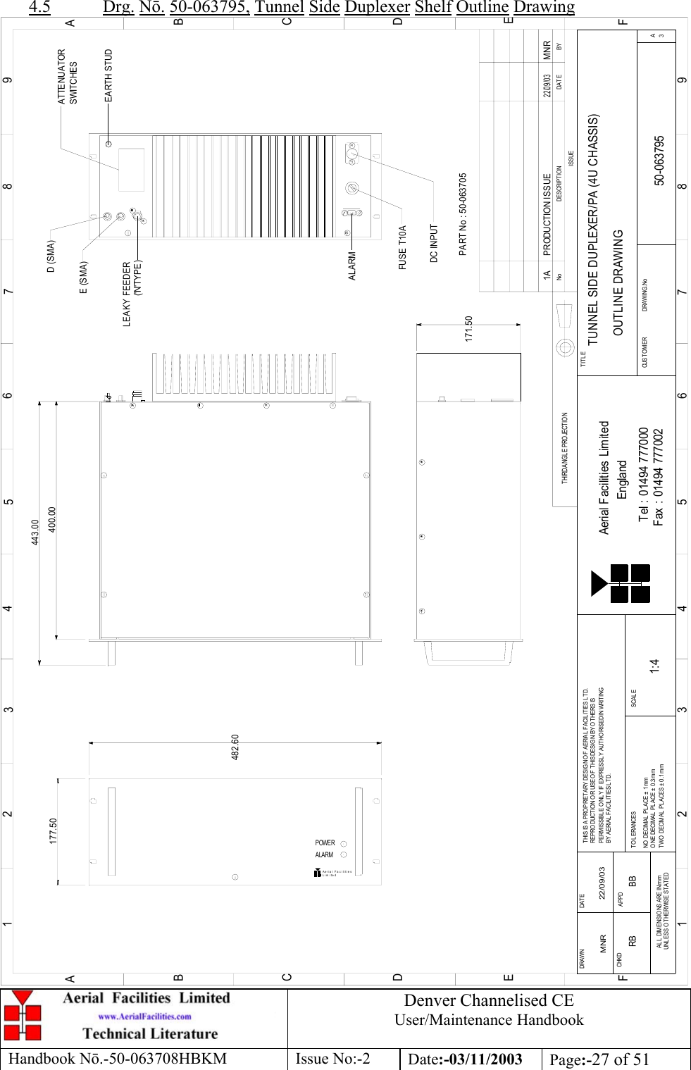
![Denver Channelised CEUser/Maintenance HandbookHandbook Nō.-50-063708HBKM Issue No:-2 Date:-03/11/2003 Page:-16 of 513.1.4 Tunnel side UHF Duplex/PA Shelf 50-063705 Parts List02-010701 5POLE COMBLINE BANDPASS FILTER 210-000701 1/4Watt 0-30dB SWITCHED ATTENUATOR 111-006102 LPA 380-500MHz 1Watt 111-007302 LNA. 380-500MHz 20dB 111-007402 LNA. 380-500MHz 30dB 112-016301 POWER AMPLIFIER 380-470MHz 20Watt CLASS A 113-001803 DUAL DC/DC CONVERTER 24V-12V 1A 117-004327 ATTENUATOR COVER 117-004730 ATTENUATOR MOUNTING 119-000826 19" CHASSIS 400mm DEEP LID 119-001021 4U 19" RACK MOUNT 400mm DEEP CHASSIS 119-001024 4U 19" CHASSIS FRONT PANEL 180-063820 HEATSINK 20Watt PA 191-030002 N ADAPTOR PANEL FEMALE/FEMALE 191-130005 SMA BULKHEAD ADAPTOR FEMALE/FEMALE 291-500001 POWER PLUG 3 PIN PANEL MOUNT NC-X 191-600014 'D' 9 WAY SOCKET (NON FILTERED) 391-600015 'D' 9 WAY PLUG (NON FILTERED) 191-600019 'D'15 WAY SHELL (2W7) 191-640004 LARGE PIN FOR 91-660001 D SOCKET 291-660001 2W5 MIXED D TYPE SOCKET (7 WAY) 196-110021 T10A 0.25 x 1.25' FUSE CERAMIC 296-110034 FUSE HOLDER 16-30A, 32mm 196-700034 LED RED 5mm IP67 196-700035 LED GREEN 5mm IP67 197-400002 4U HANDLE [ALLOY] 2](https://usermanual.wiki/PBE-Europe-as-Axell-Wireless/50-0637SERIES/User-Guide-370774-Page-16.png)
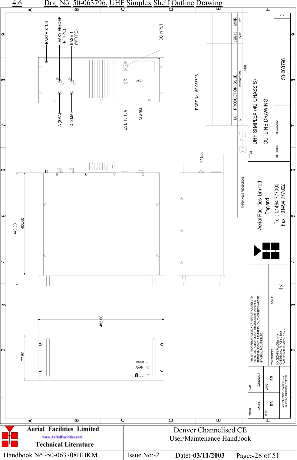
![Denver Channelised CEUser/Maintenance HandbookHandbook Nō.-50-063708HBKM Issue No:-2 Date:-03/11/2003 Page:-17 of 513.1.5 UHF Simplex Shelf 50-063706 Parts List02-010701 5POLE COMBLINE BANDPASS FILTER 208-930003 2 PORT ISOLATOR 360-470MHz SMA 110-000701 1/4Watt 0-30dB SWITCHED ATTENUATOR 111-006102 LNA 380-500MHz 1Watt 211-007402 LNA. 380-500MHz 30dB 313-001803 DUAL DC/DC CONVERTER 24V-12V 1A 213-002811 SIMPLEX CONTROLLER 117-001201 ALC ATTENUATOR 217-002802 SIMPLEX RX/SQUELCH & AF 217-004327 ATTENUATOR COVER 117-004730 ATTENUATOR MOUNTING 117-010802 CHANNEL MODULE 450MHz 8p 15kHz BW + IF OUT 219-000826 19" CHASSIS 400mm DEEP LID 119-001021 4U 19" RACK MOUNT 400mm DEEP CHASSIS 119-001024 4U 19" CHASSIS FRONT PANEL 120-001601 12V RELAY BOARD 191-030002 N ADAPTOR PANEL FEMALE/FEMALE 291-130005 SMA BULKHEAD ADAPTOR FEMALE/FEMALE 291-500001 POWER PLUG 3 PIN PANEL MOUNT NC-X 191-600014 'D' 9 WAY SOCKET (NON FILTERED) 591-600015 'D' 9 WAY PLUG (NON FILTERED) 191-620001 'D' 25 WAY SOCKET 196-110034 FUSE HOLDER 16-30A, 32mm 196-700034 LED RED 5mm IP67 196-700035 LED GREEN 5mm IP67 197-400002 4U HANDLE [ALLOY] 2](https://usermanual.wiki/PBE-Europe-as-Axell-Wireless/50-0637SERIES/User-Guide-370774-Page-17.png)