PBE Europe as Axell Wireless 50-0637SERIES UHF Signal Extender User Manual RECEIVER MULTICOUPLER
Axell Wireless UHF Signal Extender RECEIVER MULTICOUPLER
Handbook

Denver Channelised CE
User/Maintenance Handbook
Handbook Nō.-50-063708HBKM Issue No:-2 Date:-03/11/2003 Page:-1 of 51
Channelised Bi-Directional RF Amplifier
Operation & Maintenance Manual
For
Dicarlo Associates, Inc.
AFL product part Nō.: 50-063701

Denver Channelised CE
User/Maintenance Handbook
Handbook Nō.-50-063708HBKM Issue No:-2 Date:-03/11/2003 Page:-2 of 51
Table of Contents
AMENDMENT LIST RECORD SHEET ................................................................................................. 4
INTRODUCTION ....................................................................................................................................... 5
Scope...........................................................................................................................................................................5
Purpose.......................................................................................................................................................................5
Glossary of Terms .....................................................................................................................................................6
Key to AFL RF Module Drawing Symbols.............................................................................................................7
1. SAFETY CONSIDERATIONS ....................................................................................................... 8
1.1 Electric Shock Hazard .................................................................................................................................8
1.2 RF Radiation Hazard...................................................................................................................................8
1.3 Chemical Hazard..........................................................................................................................................9
1.4 Emergency Contact Numbers .....................................................................................................................9
2. OVERVIEW/SYSTEM DESCRIPTION ..................................................................................... 10
3. SPECIFICATION .......................................................................................................................... 13
3.1 50-063701 Parts Lists .................................................................................................................................13
3.1.1 UHF Duplex Shelf 50-063702 Parts List .................................................................................................13
3.1.2 Downlink UHF 5 Channel Shelf 50-063703 Parts List............................................................................14
3.1.3 Uplink UHF 4 Channel Shelf 50-063704 Parts List ................................................................................15
3.1.4 Leaky Feeder UHF Duplex/PA Shelf 50-063705 Parts List ....................................................................16
3.1.5 UHF Simplex Shelf 50-063706 Parts List................................................................................................17
3.1.6 Power Supply Shelf 50-063707 Parts List................................................................................................18
3.2 Technical Specification ..............................................................................................................................19
3.2.1 Channel Module Frequencies ..................................................................................................................20
3.3 Mechanical Specification ...........................................................................................................................21
4. SYSTEM DRAWINGS .................................................................................................................. 22
4.1 Drg. Nō. 50-063751, Channelised Cell Enhancer Rack Layout Drawing .............................................22
4.2 Drg. Nō. 50-063781, Channelised Cell Enhancer System Diagram .......................................................23
4.3 Drg. Nō. 50-063792, Base Side Duplex Shelf Outline Drawing ..............................................................24
4.3 Drg. Nō. 50-063793, Downlink Channels Shelf Outline Drawing ..........................................................25
4.4 Drg. Nō. 50-063794, Uplink Channels Shelf Outline Drawing...............................................................26
4.5 Drg. Nō. 50-063795, Tunnel Side Duplexer Shelf Outline Drawing ......................................................27
4.6 Drg. Nō. 50-063796, UHF Simplex Shelf Outline Drawing ....................................................................28
4.7 Drg. Nō. 50-063797, Power Supply Shelf Outline Drawing....................................................................29
5. SUB-UNIT MODULES.................................................................................................................. 30
5.1 UHF Duplex Shelf 50-063702 ....................................................................................................................30
5.1.1 Bandpass Filter (02-010701) ...................................................................................................................30
5.1.1.1 Description .......................................................................................................................................30
5.1.1.2 Technical Specification ....................................................................................................................30
5.1.2 3dB UHF Splitter (05-002603) ................................................................................................................31
5.1.2.1 Description .......................................................................................................................................31
5.1.2.2 Technical Specification ....................................................................................................................31
5.1.3 Ferrite Isolator (08-930003)....................................................................................................................32
5.1.3.1 Description .......................................................................................................................................32
5.1.4 ¼Watt 0- -30dB Switched Attenuator (10-000701)..................................................................................33
5.1.4.1 General Application ........................................................................................................................33
5.1.4.2 Switched Attenuators .......................................................................................................................33
5.1.5 Low Noise Amplifiers (11-006102, 11-007302 & 11-007402).................................................................34
5.1.5.1 Description .......................................................................................................................................34
5.1.5.2 Technical Specification, 11-007302.................................................................................................34
5.1.5.3 Technical Specification, 11-007402.................................................................................................35
5.1.5.4 Technical Specification, 11-006102.................................................................................................35
5.1.6 20W Power Amplifier (12-016301) ..........................................................................................................36

Denver Channelised CE
User/Maintenance Handbook
Handbook Nō.-50-063708HBKM Issue No:-2 Date:-03/11/2003 Page:-3 of 51
5.1.6.1 Description .......................................................................................................................................36
5.1.6.2 Technical Specification ....................................................................................................................36
5.2 5 Channel UHF Downlink Shelf 50-063703 .............................................................................................37
5.2.1 3dB Splitter 905-002603) See section 5.1.2 .............................................................................................37
5.2.2 3 Way Splitter/Combiner (05-003803).....................................................................................................37
5.2.2.1 Description .......................................................................................................................................37
5.2.2.2 Technical Specification ....................................................................................................................37
5.2.3 Dual DC/DC Converter (13-001803) ......................................................................................................38
5.2.3.1 Description .......................................................................................................................................38
5.2.3.2 Technical Specification ....................................................................................................................38
5.2.4 Channel Selective Module (17-003006)...................................................................................................39
5.2.4.1 Description .......................................................................................................................................39
5.2.4.2 Drg. Nō. 17-003080, Generic Channel Module Block Diagram......................................................40
5.2.5 12V Relay Board (20-001601) .................................................................................................................41
5.2.5.1 Description .......................................................................................................................................41
5.2.5.2 Technical Specification ....................................................................................................................41
5.3 UHF Uplink 4 Channel Shelf 50-063704 ..................................................................................................42
5.3.1 Four Way Splitter (05-003401)................................................................................................................42
5.3.1.1 Description .......................................................................................................................................42
5.3.1.2 Technical Specification 05-003401..................................................................................................42
5.4 UHF Duplex/PA Shelf 50-063705..............................................................................................................42
5.5 UHF Simplex Channel Shelf 60-063706 ...................................................................................................43
5.5.1 Simplex Controller PCB (13-002811)......................................................................................................43
5.5.1.1 Description .......................................................................................................................................43
5.5.2 ALC Attenuator Module (17-001201) ......................................................................................................43
5.5.2.1 Description .......................................................................................................................................43
5.5.3 Simplex Squelch Controller PCB (17-002802) ........................................................................................43
5.5.3.1 Description .......................................................................................................................................43
5.6 Power Supply Shelf 50-063707..................................................................................................................44
5.6.1 24V, 400W Power Supply Pack (96-300054)...........................................................................................44
5.6.1.1 Description .......................................................................................................................................44
5.6.1.1 Technical Specification ....................................................................................................................44
6. INSTALLATION............................................................................................................................ 45
6.1 Initial Installation Record .........................................................................................................................45
7. MAINTENANCE............................................................................................................................ 46
7.1 General Procedures....................................................................................................................................46
7.1.1 Fault Finding ...........................................................................................................................................46
7.1.2 Downlink ..................................................................................................................................................47
7.1.3 Uplink.......................................................................................................................................................47
7.1.4 Fault repair ..............................................................................................................................................47
7.1.5 Checking service ......................................................................................................................................48
7.1.6 Service Support ........................................................................................................................................48
7.2 Tools & Test Equipment............................................................................................................................48
7.3 Care of Modules .........................................................................................................................................49
7.3.1 General Comments...................................................................................................................................49
7.3.2 Module Removal (LNA’s, general procedure):........................................................................................49
7.3.3 Module Replacement (general):...............................................................................................................49
7.3.4 Power Amplifiers......................................................................................................................................49
7.3.5 Low Power Amplifier Replacement..........................................................................................................50
7.3.6 Module Transportation:...........................................................................................................................50
APPENDIX A INITIAL EQUIPMENT SET-UP CALCULATIONS............................................... 51
Denver Channelised CE
User/Maintenance Handbook
Handbook Nō.-50-063708HBKM Issue No:-2 Date:-03/11/2003 Page:-4 of 51
AMENDMENT LIST RECORD SHEET
Issue
Nō.
Date Incorporated
by
Page No.’s
Amended
Reason for new issue
1 29/09/2003 CMH 1st Issue
2 03/11/03 PLB 8 Add FCC RF exposure Note
Document Ref:-50-063708HBKM

Denver Channelised CE
User/Maintenance Handbook
Handbook Nō.-50-063708HBKM Issue No:-2 Date:-03/11/2003 Page:-5 of 51
INTRODUCTION
Scope
This handbook is for use solely with the equipment identified by the AFL Part Number
shown on the front cover. It is not to be used with any other equipment unless specifically
authorised by Aerial Facilities Limited.
Purpose
The purpose of this handbook is to provide the user/maintainer with sufficient information
to service and repair the equipment to the level agreed. Maintenance and adjustments to any
deeper level must be performed by AFL, normally at the company’s repair facility in
Chesham, England.
This handbook has been prepared in accordance with BS 4884, and AFL’s Quality
procedures, which maintain the company’s registration to ISO 9001: 1994 and to the
R&TTE Directive of the European Parliament. Copies of the relevant certificates and the
company Quality Manual can be supplied on application to the Quality Manager.
This document fulfils the relevant requirements of Article 6 of the R&TTE Directive.
Limitation of Information Notice
This manual is written for the use of technically competent operators/service persons. No
liability is accepted by AFL for use or misuse of this manual, the information contained
therein, or the consequences of any actions resulting from the use of the said information,
including, but not limited to, descriptive, procedural, typographical, arithmetical, or listing
errors.
Furthermore, AFL does not warrant the absolute accuracy of the information contained
within this manual, or it’s completeness, fitness for purpose, or scope.
AFL has a policy of continuous product development and enhancement, and as such,
reserves the right to amend, alter, update and generally change the contents, appearance and
pertinence of this document without notice.
All AFL products carry a twelve month warranty from date of shipment. The warranty is
expressly on a return to base repair or exchange basis and the warranty cover does not
extend to on-site repair or complete unit exchange.

Denver Channelised CE
User/Maintenance Handbook
Handbook Nō.-50-063708HBKM Issue No:-2 Date:-03/11/2003 Page:-6 of 51
Glossary of Terms
Repeater or
Cell Enhancer A Radio Frequency (RF) amplifier which can simultaneously
amplify and re-broadcast Mobile Station (MS) and Base
Transceiver Station (BTS) signals.
Band Selective Repeater A Cell Enhancer designed for operation on a range of channels
within a specified frequency band.
Channel Selective
Repeater A Cell Enhancer, designed for operation on specified channel(s)
within a specified frequency band. Channel frequencies may be
factory set or on-site programmable.
BTS Base Transceiver Station
C/NR Carrier-to-Noise Ratio
Downlink (D.L.) RF signals transmitted from the BTS and to the MS
Uplink (U.L.) RF signals transmitted from the MS to the BTS
RSA Receiver/Splitter Amplifier
EMC Electromagnetic Compatibility
GND Ground
DC Direct Current
AC Alternating Current
ID Identification Number
OIP3 Output Third Order Intercept Point = RFout +(C/I)/2
LED Light Emitting Diode
M.S. Mobile Station
N/A Not Applicable
N/C No Connection
NF Noise Figure
RF Radio Frequency
Rx Receiver
Tx Transmitter
S/N Serial Number
Denver Channelised CE
User/Maintenance Handbook
Handbook Nō.-50-063708HBKM Issue No:-2 Date:-03/11/2003 Page:-7 of 51
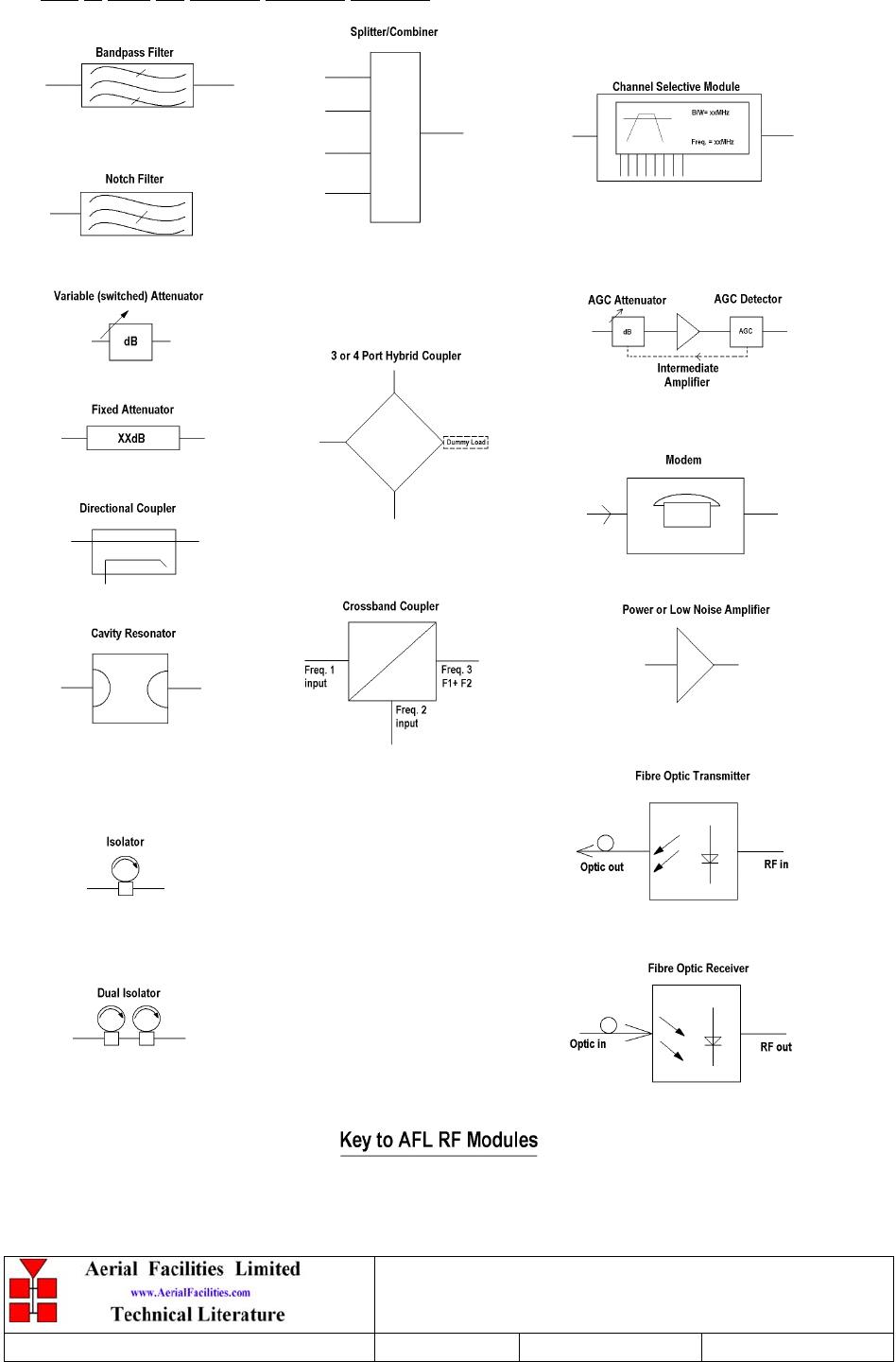
Key to AFL RF Module Drawing Symbols

Denver Channelised CE
User/Maintenance Handbook
Handbook Nō.-50-063708HBKM Issue No:-2 Date:-03/11/2003 Page:-8 of 51
1. SAFETY CONSIDERATIONS
1.1 Electric Shock Hazard
Electrical shocks due to faulty mains driven power supplies.
Whilst ever potentially present in any electrical equipment, such a condition would be
minimised by quality installation practice and thorough testing at:
a) Original assembly
b) Commissioning
c) Regular intervals, thereafter.
All test equipment to be in good working order prior to its use. High current power supplies
can be dangerous because of the possibility of substantial arcing. Always switch off during
disconnection and reconnection.
1.2 RF Radiation Hazard
RF radiation, (especially at UHF frequencies) arising from transmitter outputs connected to
AFL’s equipment, must be considered a safety hazard.
This condition might only occur in the event of cable disconnection, or because a ‘spare’
output has been left unterminated. Either of these conditions would impair the system’s
efficiency. No investigation should be carried out until all RF power sources have been
removed. This would always be a wise precaution, despite the severe mismatch between the
impedance of an N type connector at 50Ω, and that of free space at 377Ω, which would
severely mitigate against the efficient radiation of RF power. Radio frequency burns could
also be a hazard, if any RF power carrying components were to be carelessly touched!
Antenna positions should be chosen to comply with requirements (both local & statutory)
regarding exposure of personnel to RF radiation. When connected to an antenna, the unit is
capable of producing RF field strengths, which may exceed guideline safe values especially if
used with antennas having appreciable gain. In this regard the use of directional antennas
with backscreens and a strict site rule that personnel must remain behind the screen while the
RF power is on, is strongly recommended.
IMPORTANT NOTE: To comply with FCC RF exposure compliance requirements, a
separation distance of at least 20cm must be maintained between the leaky feeder attached to
this device and all persons. Furthermore the gain of antennas attached must be chosen and
located so as to satisfy the MPE categorical exclusion and co-location requirements.
Where the equipment is used near power lines, or in association with temporary masts not
having lightning protection, the use of a safety earth connected to the case-earthing bolt is
strongly advised.
Denver Channelised CE
User/Maintenance Handbook
Handbook Nō.-50-063708HBKM Issue No:-2 Date:-03/11/2003 Page:-9 of 51
1.3 Chemical Hazard
Beryllium Oxide, also known as Beryllium Monoxide, or Thermalox™, is sometimes used
in devices within equipment produced by Aerial Facilities Ltd. Beryllium oxide dust can be
toxic if inhaled, leading to chronic respiratory problems. It is harmless if ingested or by
contact.
Products that contain beryllium are load terminations (dummy loads) and some power
amplifiers. These products can be identified by a yellow and black “skull and crossbones”
danger symbol (shown above). They are marked as hazardous in line with international
regulations, but pose no threat under normal circumstances. Only if a component containing
beryllium oxide has suffered catastrophic failure, or exploded, will there be any danger of the
formation of dust. Any dust that has been created will be contained within the equipment
module as long as the module remains sealed. For this reason, any module carrying the
yellow and black danger sign should not be opened. If the equipment is suspected of failure,
or is at the end of its life-cycle, it must be returned to Aerial Facilities Ltd for disposal.
To return such equipment, please contact the Quality Department, who will give you a
Returned Materials Authorisation (RMA) number. Please quote this number on the packing
documents, and on all correspondence relating to the shipment.
PolyTetraFluoroEthylene, (P.T.F.E.) and P.T.F.E. Composite Materials
Many modules/components in AFL equipment contain P.T.F.E. as part of the RF insulation
barrier.
This material should never be heated to the point where smoke or fumes are evolved. Any
person feeling drowsy after coming into contact with P.T.F.E. especially dust or fumes
should seek medical attention.
1.4 Emergency Contact Numbers
The AFL Quality Department can be contacted on:
Telephone +44 (0)1494 777000
Fax +44 (0)1494 777002
e-mail qa@aerial.co.uk

Denver Channelised CE
User/Maintenance Handbook
Handbook Nō.-50-063708HBKM Issue No:-2 Date:-03/11/2003 Page:-10 of 51
2. OVERVIEW/SYSTEM DESCRIPTION
The equipment covered in this manual is a UHF Bi-directional Amplifier (also known as a
Repeater). Its main sphere of application is in urban areas where the topography is such that
shadows occur in the propagation pattern (for example within large buildings, conference
centres and tunnels, etc.)
The Amplifier is a 4-port device for direct connection to two Base facing antennas, usually a
highly directional Yagi or similar aligned towards the base (donor) site, and two radiating
cable feeders to cover the mobiles. The channel frequencies passed by the Amplifier are set
as per the specific customer requirements. In this instance, the channel module frequencies
have been ‘hard-wired’ and so it is not possible to change frequencies without some re-
configuration of the channel programming.
The system for which the Amplifier is to be used with is mainly duplex channel UHF radio
system but with a single simplex channel. The duplex channels operate constantly in each
direction using the Base Antenna port 2 and Radiating Cable port 2. There are five
Downlink (Base Transmit) duplex channels and four Uplink (Base Receive) duplex
channels. In addition there is the Uplink simplex (talkaround) channel operating via these
ports.
The Downlink simplex channel operates through the Base Antenna port 1 and Radiating
Cable port 1 ports. This is to avoid any interaction between the common frequency channel
high gain paths. Using separate antennas adds the isolation required for the simplex part of
the Amplifier to work.
The simplex channels are not constantly operating in their entirety. Instead, each simplex
path has the output amplification disabled and when an input is detected in one path that
amplifier will be switched on and the other path will be held off until that input signal has
stopped. In this way, the simplex part of the system is constantly ready to pass the channel in
either path.
The Bi-directional Amplifier consists of six different 19” rack mount 4U chassis. These are
a Base side Duplex/PA chassis (AFL part: 50-063702) to provide the link with Antenna 2
and the remainder of the system. In addition there is a Tunnel side Duplex/PA chassis (AFL
part: 50-063705) to connect the Radiating cable 2 to the remainder of the system. The
channel selectivity is made in the Downlink by a Downlink Channel chassis (AFL part: 50-
063703) and in the Uplink by the Uplink Channel chassis (AFL part: 50-063704). The
Downlink simplex channel and part of the Uplink simplex channel circuit is housed in the
Simplex chassis (AFL part: 50-063706) and there is a Power Supply chassis (AFL part: 50-
063707) to provide the DC supply to each of the five RF units.
The Bi-directional Amplifier is housed in a single 38U 19” rack. All external connections
are made towards the bottom of the rear of the rack suitable for cable entry via cable ducts
through the open underside of the rack. External connections are for the 110V AC input,
four ‘N’ type female RF connectors and a Krone block for the alarm output.

Denver Channelised CE
User/Maintenance Handbook
Handbook Nō.-50-063708HBKM Issue No:-2 Date:-03/11/2003 Page:-11 of 51
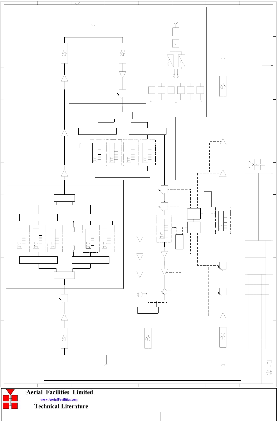
For better understanding of the system, the system diagram on page 23 should be consulted.
Downlink path
Duplex system signals in the Downlink path arriving at Base Antenna port 2 are first passed
to the Base side chassis and so through a duplexed bandpass filter to ensure good input
selectivity. This is then followed by a 31dB gain LNA to provide some amplification and a
switchable attenuator then allows up to 30dB of gain adjustment in 2dB steps.
From here signals are routed to the Downlink Channel chassis where a 2 way splitter is
followed by two three way splitters to provide six equal paths. One of these is terminated
with a 50ohm load and the remaining five each connect to a channel selectivity module. The
Downlink channel modules offer 15dB gain and have ALC circuitry to limit the module
output to -25dBm. This is ensure that the total output power may not become higher than the
specified level. The channel module outputs are taken to two three way combiners for
connection to a two way combiner which then routes signals out of the Downlink Channel
chassis and to the Tunnel side chassis.
The Downlink duplex channel frequencies factory set are:
457.050MHz
458.225MHz
457.850MHz
457.300MHz
457.775MHz
In the Tunnel side chassis a 21dB gain LNA is then followed by a 15dB gain LPA to drive a
23dB gain 20Watt Power Amplifier which provides the final stage of amplification. The
Power Amplifier is followed by a duplexed bandpass filter connecting to the Radiating cable
port 2.
The Downlink simplex channel, 452.850MHz, is received at Base Antenna port 1 and is
passed through a bandpass filter to provide selectivity. A 31dB gain LNA then provides
initial amplification and this is followed by a switchable attenuator giving up to 30dB of
gain adjustment in 2dB steps. An ALC attenuator is then fitted for muting the input of the
channel module when an Uplink path signal has been detected and is being amplified in that
direction. The channel module following the attenuator has 15dB of gain and has ALC
circuitry to limit the module output to -20dBm to limit the total output power to that
specified in case of an increase in off-air signal input. The channel module is followed by a
31dB gain LNA and then a 15dB gain 1Watt LPA. A bandpass filter after the LPA connects
to the Radiating cable port 1.
Uplink path
All Uplink channels enter the Bi-Directional Amplifier at Radiating Cable port 2 and pass to
the Tunnel side chassis where a duplexed bandpass filter routes the signals to the Uplink
input amplifier, a 31dB gain LNA. A switchable attenuator then gives up to 30dB of gain
adjustment in 2dB steps before signals connect to the Uplink Channel chassis.
In the Uplink Channel chassis, a 2 way splitter connects to two three way splitters to provide
six equal paths. One of these is unused and so is terminated with a 50ohm load. Four of the
remaining paths each connect to a channel selectivity module giving 15dB gain with an
ALC limited maximum output of -23dBm. The four module outputs then connect to a four
way combiner for routing to the Base side chassis. The last of the six paths is routed to the
Simplex chassis which will be described later in this section.

Denver Channelised CE
User/Maintenance Handbook
Handbook Nō.-50-063708HBKM Issue No:-2 Date:-03/11/2003 Page:-12 of 51
The Uplink duplex channel frequencies are factory set:
452.050MHz
453.225MHz
452.300MHz
452.775MHz
The four Uplink duplex channels arrive in the Base side chassis and pass through a 21dB
gain then a 15dB gain LPA driver before a 23dB gain 20Watt Power Amplifier. There is an
isolator fitted at the PA output to provide protection from the Uplink simplex channel path.
A 2 way combiner then combines the four duplex channels with the simplex channel and a
bandpass filter then connects to the Base Antenna port 2.
In the Simplex chassis, the Uplink path from the Uplink Channel chassis is first routed
through two ALC attenuators to mute the input to the Uplink channel selectivity module
when a Downlink simplex signal is being passed in the other path. A channel selectivity
module, set for 452.850MHz, then gives 25dB of gain and has an ALC level of -17dBm.
The module is followed by a 31dB gain LNA and then a 15dB gain LPA with an isolator at
the output to provide protection from the duplex path PA. The Uplink simplex signal then
connects to the Mobile side chassis for routing to the 2 way combiner.
The Power Supply Unit operates from an AC supply of 110V and has a 7.5Ampere circuit
breaker to switch the chassis On or Off. A 15A filter then provides some protection against
instabilities in the AC supply. There are two 400Watt PSU modules fitted and the outputs of
these are distributed to six 24V DC output sockets at the rear of the Power Supply chassis.
The RF connectors used for user interface are ‘N’ type female and interconnecting RF
chassis connectors are SMA female. Each of the five RF chassis has a DC input fuse and the
front panels have a green ‘Power ON’ LED and a red ‘ Alarm’ LED. The Power Supply
chassis has a single green ‘Power ON’ front panel LED.
Each chassis has a summary alarm output connecting to the Krone block at the lower rear of
the rack for user interface. In addition, the 19” rack has intruder alarms fitted to the front and
rear doors of the rack. The alarm outputs may be connected to singly or in parallel as a rack
summary. The alarm outputs are voltage free dry contacts being Closed in normal operation
and Open in an Alarm state.
Denver Channelised CE
User/Maintenance Handbook
Handbook Nō.-50-063708HBKM Issue No:-2 Date:-03/11/2003 Page:-13 of 51
3. SPECIFICATION
3.1 50-063701 Parts Lists
50-063702 BASE ANT SIDE UHF DUPLEX/PA CHASSIS 1
50-063703 DOWNLINK UHF 5 CHANNEL CHASSIS 1
50-063704 UPLINK UHF 4 CHANNEL CHASSIS 1
50-063705 LCX SIDE UHF DUPLEX/PA CHASSIS 1
50-063706 UHF SIMPLEX CHANNEL CHASSIS 1
50-063707 POWER SUPPLY CHASSIS, 110V AC INPUT 1
97-500033 38U RACK 38U 600 x 600mm RAL7035 1
97-500065 EURORACK GND/EARTHING KIT 1
3.1.1 Base Antenna Side UHF Duplex/PA Shelf 50-063702 Parts List
02-010701 5POLE UHF COMBLINE BANDPASS FILTER 2
05-002603 UHF 3dB SPLITTER SMA 1
08-004905 25Watt 2 PORT ISOLATOR N 330-470MHz 1
10-000701 1/4Watt 0-30dB SWITCHED ATTENUATOR 1
11-006102 LPA 380-500MHz 1Watt 1
11-007302 LNA. 380-500MHz 20dB 1
11-007402 LNA. 380-500MHz 30dB 1
12-016301 POWER AMPLIFIER 380-470MHz 20Watt CLASS A 1
17-004327 ATTENUATOR COVER 1
17-004730 ATTENUATOR MOUNTING 1
19-000826 19" CHASSIS 400mm DEEP LID 1
19-001021 4U 19" RACKMOUNT 400mm DEEP CHASSIS 1
19-001024 4U 19" CHASSIS FRONT PANEL 1
80-063820 HEATSINK 20Watt PA 1
91-030002 N ADAPTOR PANEL FEMALE/FEMALE 1
91-130005 SMA BULKHEAD ADAPTOR FEMALE/FEMALE 2
91-500001 POWER PLUG 3 PIN PANEL MOUNT NC-X 1
91-600014 'D' 9 WAY SOCKET (NON FILTERED) 3
91-600015 'D' 9 WAY PLUG (NON FILTERED) 1
91-600019 'D'15 WAY SHELL (2W7) 1
91-640004 LARGE PIN FOR 91-660001 D SOCKET 2
91-660001 2W5 MIXED D TYPE SOCKET (7 WAY) 1
96-110021 T10A 0.25 x 1.25' FUSE CERAMIC 2
96-110034 FUSE HOLDER 16-30A, 32mm 1
96-700034 LED RED 5mm IP67 1
96-700035 LED GREEN 5mm IP67 1
97-400002 4U HANDLE [ALLOY] 2
Denver Channelised CE
User/Maintenance Handbook
Handbook Nō.-50-063708HBKM Issue No:-2 Date:-03/11/2003 Page:-14 of 51
3.1.2 Downlink UHF 5 Channel Shelf 50-063703 Parts List
05-002603 UHF 3dB SPLITTER SMA 2
05-003803 3 WAY SPLITTER, UHF 4
13-001803 DUAL DC/DC CONVERTER 24V-12V 1A 2
17-003012 CHANNEL MODULE 450MHz, 15kHz (8p) 5
19-000826 19" CHASSIS 400mm DEEP LID 1
19-001021 4U 19" RACK MOUNT 400mm DEEP CHASSIS 1
19-001024 4U 19" CHASSIS FRONT PANEL 1
20-001601 12V RELAY BOARD 3
91-130005 SMA BULKHEAD ADAPTOR FEMALE/FEMALE 2
91-500001 POWER PLUG 3 PIN PANEL MOUNT NC-X 1
91-600015 'D' 9 WAY PLUG (NON FILTERED) 1
91-620001 'D' 25 WAY SOCKET 5
93-930003 SMA 50ohm TERMINATION 2
96-110001 FUSE HOLDER 20 x 5mm6.3A 1
96-110011 T 4A A.SURGE FUSE 20mm 2
96-600002 INSULATING BOOT SMALL 1
96-600003 INSULATING BOOT D.C. 1
96-700034 LED RED 5mm IP67 1
96-700035 LED GREEN 5mm IP67 1
97-400002 4U HANDLE [ALLOY] 2
Denver Channelised CE
User/Maintenance Handbook
Handbook Nō.-50-063708HBKM Issue No:-2 Date:-03/11/2003 Page:-15 of 51
3.1.3 Uplink UHF 4 Channel Shelf 50-063704 Parts List
05-002603 UHF 3dB SPLITTER SMA 1
05-003401 4 WAY SPLITTER LOW POWER 1
05-003803 3 WAY SPLITTER, UHF 2
13-001803 DUAL DC/DC CONVERTER 24V-12V 1A 2
17-003012 CHANNEL MODULE 450MHz, 15kHz (8p) 4
19-000826 19" CHASSIS 400mm DEEP LID 1
19-001021 4U 19" CHASSIS 400mm DEEP CHASSIS 1
19-001024 4U 19" CHASSIS FRONT PANEL 1
20-001601 12V RELAY BOARD 2
91-130005 SMA BULKHEAD ADAPTOR FEMALE/FEMALE 3
91-500001 POWER PLUG 3 PIN PANEL MOUNT NC-X 1
91-600015 'D' 9 WAY PLUG 1
91-620001 'D' 25 WAY SOCKET 4
93-930003 SMA 50ohm TERMINATION 1
96-110001 FUSE HOLDER 20 x 5mm6.3A 1
96-110011 T 4A A.SURGE FUSE 20mm 2
96-600002 INSULATING BOOT SMALL 1
96-600003 INSULATING BOOT D.C. 1
96-700034 LED RED 5mm IP67 1
96-700035 LED GREEN 5mm IP67 1
97-400002 4U HANDLE [ALLOY] 2
Denver Channelised CE
User/Maintenance Handbook
Handbook Nō.-50-063708HBKM Issue No:-2 Date:-03/11/2003 Page:-16 of 51
3.1.4 Tunnel side UHF Duplex/PA Shelf 50-063705 Parts List
02-010701 5POLE COMBLINE BANDPASS FILTER 2
10-000701 1/4Watt 0-30dB SWITCHED ATTENUATOR 1
11-006102 LPA 380-500MHz 1Watt 1
11-007302 LNA. 380-500MHz 20dB 1
11-007402 LNA. 380-500MHz 30dB 1
12-016301 POWER AMPLIFIER 380-470MHz 20Watt CLASS A 1
13-001803 DUAL DC/DC CONVERTER 24V-12V 1A 1
17-004327 ATTENUATOR COVER 1
17-004730 ATTENUATOR MOUNTING 1
19-000826 19" CHASSIS 400mm DEEP LID 1
19-001021 4U 19" RACK MOUNT 400mm DEEP CHASSIS 1
19-001024 4U 19" CHASSIS FRONT PANEL 1
80-063820 HEATSINK 20Watt PA 1
91-030002 N ADAPTOR PANEL FEMALE/FEMALE 1
91-130005 SMA BULKHEAD ADAPTOR FEMALE/FEMALE 2
91-500001 POWER PLUG 3 PIN PANEL MOUNT NC-X 1
91-600014 'D' 9 WAY SOCKET (NON FILTERED) 3
91-600015 'D' 9 WAY PLUG (NON FILTERED) 1
91-600019 'D'15 WAY SHELL (2W7) 1
91-640004 LARGE PIN FOR 91-660001 D SOCKET 2
91-660001 2W5 MIXED D TYPE SOCKET (7 WAY) 1
96-110021 T10A 0.25 x 1.25' FUSE CERAMIC 2
96-110034 FUSE HOLDER 16-30A, 32mm 1
96-700034 LED RED 5mm IP67 1
96-700035 LED GREEN 5mm IP67 1
97-400002 4U HANDLE [ALLOY] 2

Denver Channelised CE
User/Maintenance Handbook
Handbook Nō.-50-063708HBKM Issue No:-2 Date:-03/11/2003 Page:-17 of 51
3.1.5 UHF Simplex Shelf 50-063706 Parts List
02-010701 5POLE COMBLINE BANDPASS FILTER 2
08-930003 2 PORT ISOLATOR 360-470MHz SMA 1
10-000701 1/4Watt 0-30dB SWITCHED ATTENUATOR 1
11-006102 LNA 380-500MHz 1Watt 2
11-007402 LNA. 380-500MHz 30dB 3
13-001803 DUAL DC/DC CONVERTER 24V-12V 1A 2
13-002811 SIMPLEX CONTROLLER 1
17-001201 ALC ATTENUATOR 2
17-002802 SIMPLEX RX/SQUELCH & AF 2
17-004327 ATTENUATOR COVER 1
17-004730 ATTENUATOR MOUNTING 1
17-010802 CHANNEL MODULE 450MHz 8p 15kHz BW + IF OUT 2
19-000826 19" CHASSIS 400mm DEEP LID 1
19-001021 4U 19" RACK MOUNT 400mm DEEP CHASSIS 1
19-001024 4U 19" CHASSIS FRONT PANEL 1
20-001601 12V RELAY BOARD 1
91-030002 N ADAPTOR PANEL FEMALE/FEMALE 2
91-130005 SMA BULKHEAD ADAPTOR FEMALE/FEMALE 2
91-500001 POWER PLUG 3 PIN PANEL MOUNT NC-X 1
91-600014 'D' 9 WAY SOCKET (NON FILTERED) 5
91-600015 'D' 9 WAY PLUG (NON FILTERED) 1
91-620001 'D' 25 WAY SOCKET 1
96-110034 FUSE HOLDER 16-30A, 32mm 1
96-700034 LED RED 5mm IP67 1
96-700035 LED GREEN 5mm IP67 1
97-400002 4U HANDLE [ALLOY] 2
Denver Channelised CE
User/Maintenance Handbook
Handbook Nō.-50-063708HBKM Issue No:-2 Date:-03/11/2003 Page:-18 of 51
3.1.6 Power Supply Shelf 50-063707 Parts List
80-008902 24V RELAY PCB ASSEMBLY 1
80-008920 DUAL PSU HEATSINK 2
80-008921 DUAL PSU CASE 1
80-008922 DUAL PSU LID 1
80-008925 DUAL PSU FRONT PANEL 1
91-510004 3 PIN PANEL MOUNT SOCKET NC-X 6
91-510035 3 WAY MATE N LOK PLUG HOUSING 2
91-520001 POWER MAINS INLET FIXED 1
91-520005 MAINS LEAD (IEC) 1
91-520010 MAINS RETAINING CLIP 1
91-520032 MATE N LOK SOCKET CONTACT 20/14 AWG 6
91-600015 'D' 9 WAY PLUG (NON FILTERED) 1
91-700017 ICD 15 WAY 0.1' CONNECTOR 1
91-700062 6 WAY 0.1' CONNECTOR 2
91-800015 TRIPLE DECK TERMINAL BLOCK 6
91-800016 TRIPLE DECK TERMINAL JUMPER 2
91-800017 TRIPLE DECK TERMINAL END 1
91-800031 SYMETRIC 35 x 7.5mm DIN RAIL 1
92-900014 DIN RAIL (TOP HAT) EARTH CLAMP M5 1
96-300054 24V 17A PSU 400W (XP BCC) 2
96-500005 DC INPUT FILTERS 6
96-500009 SURGE FILTER, 15A, 110V, DIN RAIL 1
96-600001 INSULATING BOOT LARGE 1
96-700034 LED RED 5mm IP67 1
96-700035 LED GREEN 5mm IP67 1
Denver Channelised CE
User/Maintenance Handbook
Handbook Nō.-50-063708HBKM Issue No:-2 Date:-03/11/2003 Page:-19 of 51
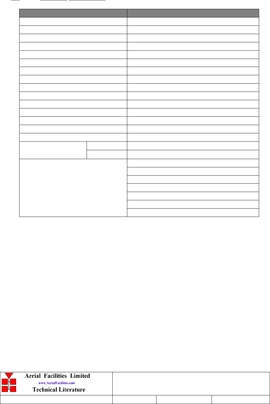
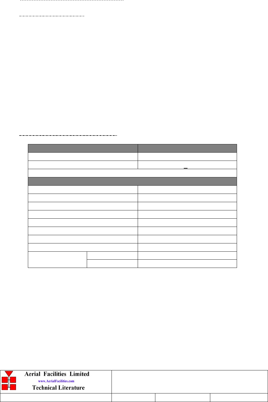
3.2 Technical Specification
PARAMETER SPECIFICATION
Frequency range: 457.0-458.5MHz (Downlink) + 452.850MHz
452.0-453.5MHz (Uplink)
Bandwidth: 1.5MHz
Gain: 80dB (70dB +/- 10dB)
Gain Adjustment: 0 - 30dB (in 2dB steps)
Channel Bandwidth: 15kHz
Channel Selectivity: > 20dBc at +/-12.5kHz
Uplink Power output: +23dBm per channel
Downlink Power output: +23dBm per channel
OIP3: Uplink +50dBm
Downlink +54dBm
In-band Spurious Noise Figure: <-36dBm (30kHz B/W)
ALC: Fitted in each channel module
VSWR: better than 1.5:1
RF Connectors: N type, female
operational: -30°C to +60°C
Temperature range:
storage: -40°C to +70°C
1 PSU Chassis
2 Tunnel side Chassis
3 Base side Chassis
4 Simplex Chassis
5 Downlink Channels Chassis
6 Uplink Channels Chassis
Summary alarm:
(volt-free contacts at Krone block)
7 Rack Doors Open
Denver Channelised CE
User/Maintenance Handbook
Handbook Nō.-50-063708HBKM Issue No:-2 Date:-03/11/2003 Page:-20 of 51
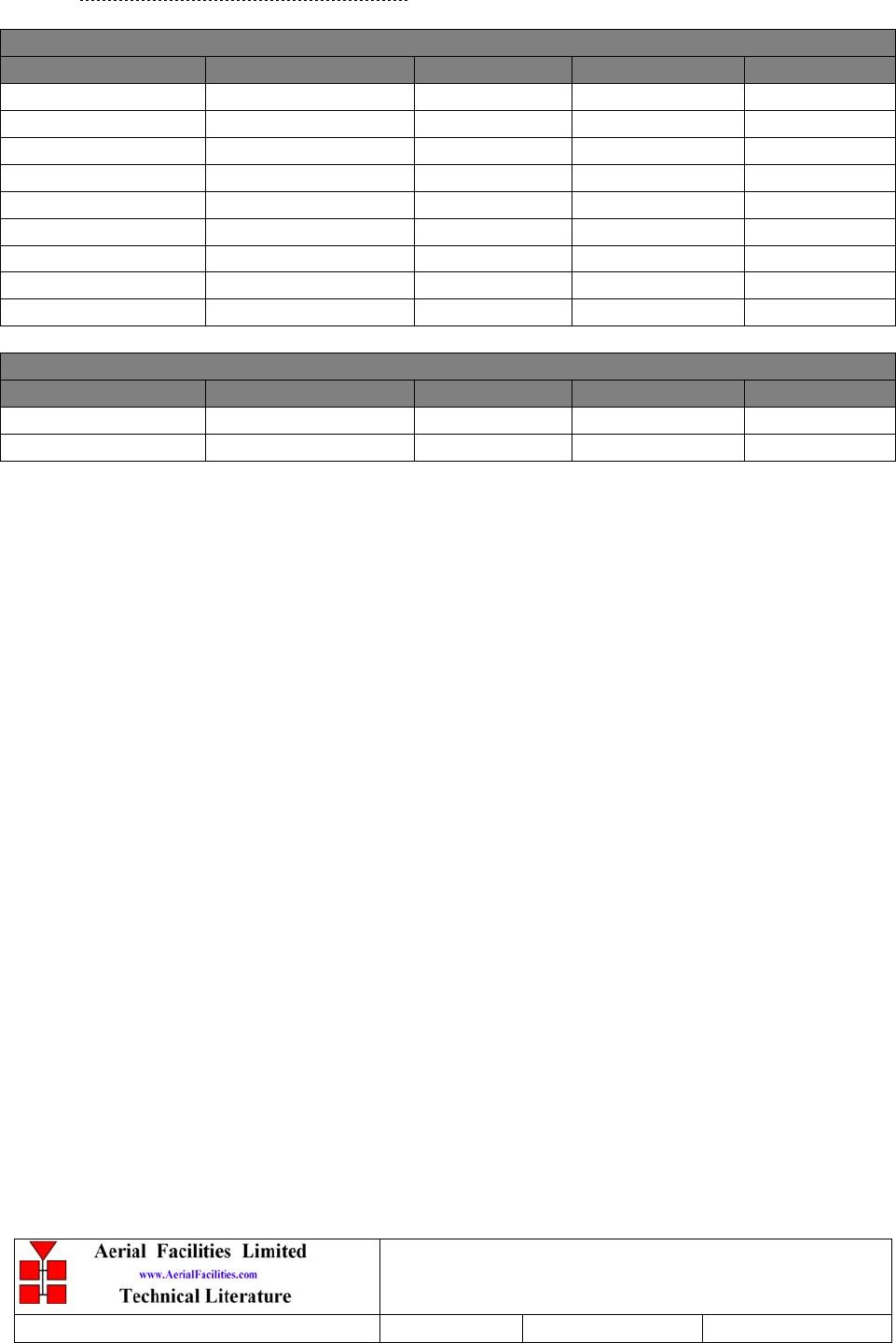
3.2.1 Channel Module Frequencies
17-003012 Duplex Channel Modules
Frequency (MHz) Bandwidth Gain ALC Qty.
457.050 (Downlink) 15kHz 15dB -25dBm 1
457.300 (Downlink) 15kHz 15dB -25dBm 1
457.775 (Downlink) 15kHz 15dB -25dBm 1
457.850 (Downlink) 15kHz 15dB -25dBm 1
458.225 (Downlink) 15kHz 15dB -25dBm 1
452.050 (Uplink) 15kHz 15dB -23dBm 1
452.300 (Uplink) 15kHz 15dB -23dBm 1
457.775 (Uplink) 15kHz 15dB -23dBm 1
453.225 (Uplink) 15kHz 15dB -23dBm 1
17-010802 Simplex Channel Modules
Frequency (MHz) Bandwidth Gain ALC Qty.
452.850(Uplink) 15kHz 25dB -17dBm 1
452.850(Downlink) 15kHz 15dB -20dBm 1
All with hardwired frequency selection
Denver Channelised CE
User/Maintenance Handbook
Handbook Nō.-50-063708HBKM Issue No:-2 Date:-03/11/2003 Page:-21 of 51
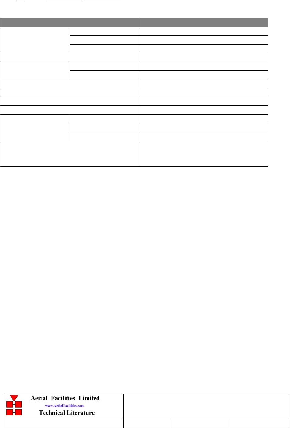
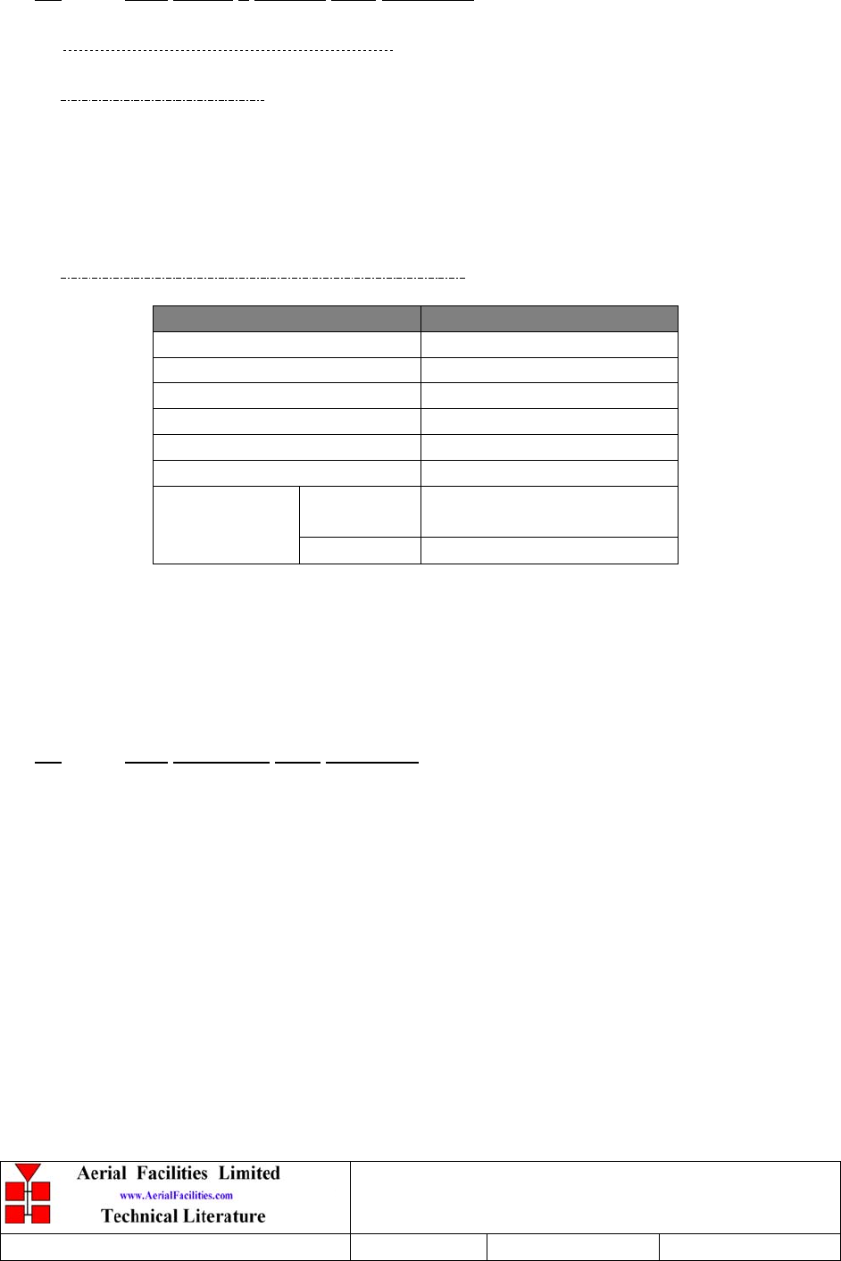
3.3 Mechanical Specification
PARAMETER SPECIFICATION
Height: 38U Eurorack (1U=44.5mm)
Width: 600mmCase (rack) size:
Depth: 600mm
operational: -30°C to +60°C
Temperature Range: storage: -40°C to +70°C
Weight: >100kg*
Humidity: 10 – 90% non-condensing
RF Connectors: N type female
Environmental Protection: IP40
Shelves: Alocrom
Heatsinks: Black anodisedFinish:
Handles: Alloy
Supply Cable:
Unit supplied with suitable supply input
leads with connector and specified
length of cable.
* Note: Individual shelf weights not specified.
Denver Channelised CE
User/Maintenance Handbook
Handbook Nō.-50-063708HBKM Issue No:-2 Date:-03/11/2003 Page:-22 of 51
4. SYSTEM DRAWINGS
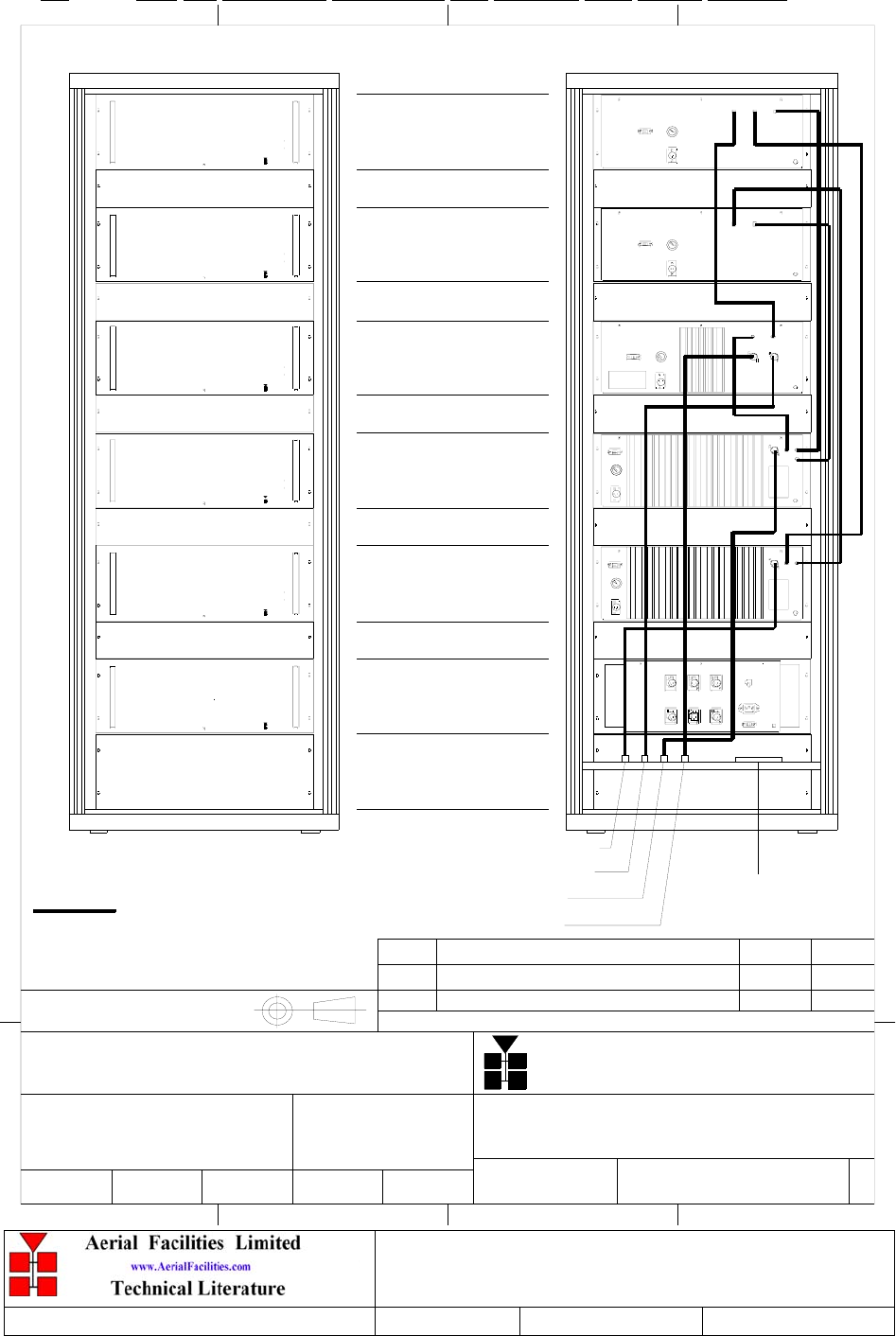
4.1 Drg. Nō. 50-063751, Channelised Cell Enhancer Rack Layout Drawing
THIRD ANGLE PROJECTI ON
1234
A
B
C
D
E
F F
E
D
C
B
A
4
321
No DESCRIPTION
ISSUE
DATE BY
BY AERIAL FACILITIES LTD.
TWO DECIMAL PLACES ± 0.1mm
ONE DECIMAL PLACE ± 0.3mm
NO DECIMAL PLACE ± 1m m
PERMISSIBLE ONLY IF EXPRESSLY AUTHORISED IN WRITING
REP RODUCT ION OR USE OF T HIS DE S IGN B Y OT HE RS IS
THIS IS A PROPRIETARY DESIGN OF AERIAL FACILITIES LTD.
TOLERANCES
DRAWN DATE APPD
CHKD
mm UNLESS OTHERWISE
ALL DIMENSIONS ARE IN
STATED
SCALE
T el : 01494 777000 F ax : 01494 777002
Aerial Facilities Limited
CUST OM E R
TITLE
DRAWING No
A
4
RACK INTERCONNECTION AND LAYOUT
FOR 5 CHN UHF CHANNELISED CE 80dB
50-063751
1A
1: 10MNR 23/ 09/ 03
Limit ed
Aer ial Fa cilit ie s
Limit ed
Aer ial Fa cilit ie s
50-063704
2U SPACE
50-063703
2U SPACE
50-063706
2U SPACE
50-063702
2U SPACE
50-063705
2U SPACE
50-063707
4U SPACE
PRODUCTION ISSUE MNR
23/ 09/ 03
Limit ed
Aer ial Fa cilit ie s
Limit ed
Aer ial Fa cilit ie s
Limit ed
Aer ial Fa cilit ie s
Limit ed
Aer ial Fa cilit ie s
OFF
ON
FRONT BACK
RF INTERCONNECTION CABLES
ALARM
POWER
ALARM
POWER
ALARM
POWER
ALARM
POWER
ALARM
POWER
ALARM OUTPUT
BASE PORT 1
BASE PORT 2
LEAKY FEEDER 1
LEAKY FEEDER 2
RB BB
Denver Channelised CE
User/Maintenance Handbook
Handbook Nō.-50-063708HBKM Issue No:-2 Date:-03/11/2003 Page:-23 of 51
4.2 Drg. Nō. 50-063781, Channelised Cell Enhancer System Diagram
5 CHN UHF CHANNELISED CE 80dB
SYSTEM DIAGRAM
50-063781
1A
-
MNR 30/07/03
dB
dB
dB
dB dB
SQUELCH
SQUELCH
BANDPASS FILTER
457-458.5MHz
02-010701
LNA
31dB GAIN
11-007402 10-000701
0-30dB
ATTENUATOR
SPLITTER
05-002603
SPL ITTER
05-003803
5 x CHANNEL MO DUL E
17-003012
05-003803
CO M BINER
05-003803
SPL ITTER
05-003803
CO M BINER
CO M BINER
05-002603 LNA
21dB GAIN
11-007302 11-006102
LPA
15dB GAIN
12-016301
23dB GAIN
20W PA
02-010701
457-458.5MHz
BANDPASS FIL TER
02-010701
452-453.5MHz
BANDPASS FILTER
SPL ITTER
05-002603
ISOLATOR
08-004905 11-006102
15dB GAIN
LPA
12-016301
23dB GAIN
20W PA
11-007302
21dB GAIN
LNA
AT T E NUAT O R
10-000701
0-30dB LNA
11-007402
31dB GAIN 452-453.5MHz
BANDPASS FIL TER
02-010701
05-002603
SPLITTER
05-003803
SPL ITTER
SPL ITT ER
05-003803
05-003401
CO M BINER
08-004905
ISOLATOR
11-006102
15dB GAIN
LPA AGC ATT.
17-001201
451.5-453MHz
BANDPASS FILTER
02-010701
451.5-453MHz
02-010701
BANDPASS FILTER
ATT ENUATOR
10-000701
0-30dB
17-001201
AGC ATT.
31dB GAIN
11-007402
LNA
31dB GAIN
LNA
11-007402 11-006102
15dB GAIN
LPA
4 x CHANNEL MO DUL E
17-003012
CHANNEL M O DUL E
17-010802
CHANNEL MO DULE
17-010802
11-007402
31dB GAIN
LNA
17-002802
17-002802
ANT
F ACI NG
BASE 2
F ACI NG
BASE 1
ANT
FEEDER
L EAKY
PORT 1
PORT 2
FEEDER
L EAKY
50-063702
BASE SIDE
DUPL EX/PA
CHASSIS,4U
50-063703
DO WNL INK
CHANNEL S
4U
CHANNEL S
UPL INK
50-063704
4U
LCX SIDE
50-063705
CHASSIS ,4 U
DUPL EX/PA
50-063707
PSU CHASSIS
110V
AC
INPUT
OUTPUT
TO
DC
6 x DC FIL TERS
400W
PSU
400W
PSU
7.5A MCB
96-920045
96-500009
FILTER
AC
15A
FREQUENCY PROGRAMMING DATA
B/W=15kHz
FREQUENCY PROGRAMMING DATA
B/W=15kHz
FREQUENCY PROGRAMMING DATA
B/W=15kHz
FREQUENCY PROGRAMMING DATA
B/W=15kHz
FREQUENCY PROGRAMMING DATA
B/W=15kHz
FREQUENCY PROGRAMMING DATA
B/W=15kHz
FREQUENCY PROGRAMMING DATA
B/W=15kHz
FREQUENCY PROGRAMMING DATA
B/W=15kHz
FREQUENCY PROGRAMMING DATA
B/W=15kHz
FREQUENCY PROGRAMMING DATA
B/W=15kHz
FREQUENCY PROGRAMMING DATA
B/W=15kHz
24V
UNITS
457. 050M H z
457. 300M H z
457. 775M H z
457. 850M H z
458. 225M H z
452. 050M H z
452. 300M H z
452. 775M H z
453. 225M H z
452. 850M H z
452. 850M H z
DATEDESCRIPTIONNo
ISSUE
THIRD ANGL E PRO JECTION
123456789101112
A
B
C
D
E
F
G
H
123456789101112
A
B
C
D
E
F
G
H
PERMISSIBLE ONLY IF EXPRESSLY AUTHORISED IN WRITING
RE PRODUCTI ON OR US E OF THIS DE SIGN BY OTH ERS IS
THIS IS A PROPRIETARY DESIGN OF AERIAL FACILITIES LTD.
UNLESS OTHERWISE STATED
ALL DIMENSIONS ARE IN mm
DATEDRAWN
CHKD APPD
TWO DECIMAL PLACES ± 0.1mm
NO DECIMAL PLACE ± 1mm
ONE DECIMAL PLACE ± 0.3mm
BY AERIAL FACILITIES LTD.
TOLERANCES SCALE
CUSTOME R DRAWING No
Fax : 01494 777002
Tel : 01494 777000
Aerial Facilities Limited
England
TI TLE
2
A
PRO DUCT IO N ISSUE MNR
30/ 07/ 03
GAIN 15dB
ALC -25dBm
17-001201
AGC ATT.
dB
2 x SIMPLEX
CO NTRO L L ER
13-002811
RB PB
CHASSIS,4U
UHF SIMPL EX
50-063706
ADDING TEXT
23/ 09/ 03
MNR1B
BY
ALC -23dBm
GAIN 15dB
AL C -1 7 dBm
G AIN 2 5d B
ALC -2 0 d Bm
GAIN 15dB
Denver Channelised CE
User/Maintenance Handbook
Handbook Nō.-50-063708HBKM Issue No:-2 Date:-03/11/2003 Page:-24 of 51
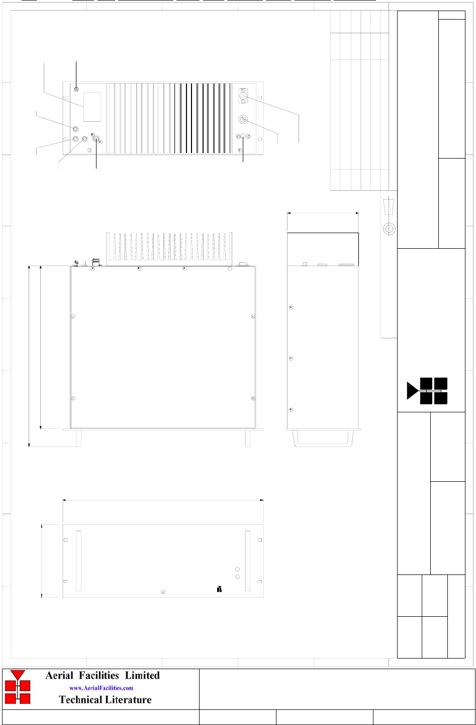
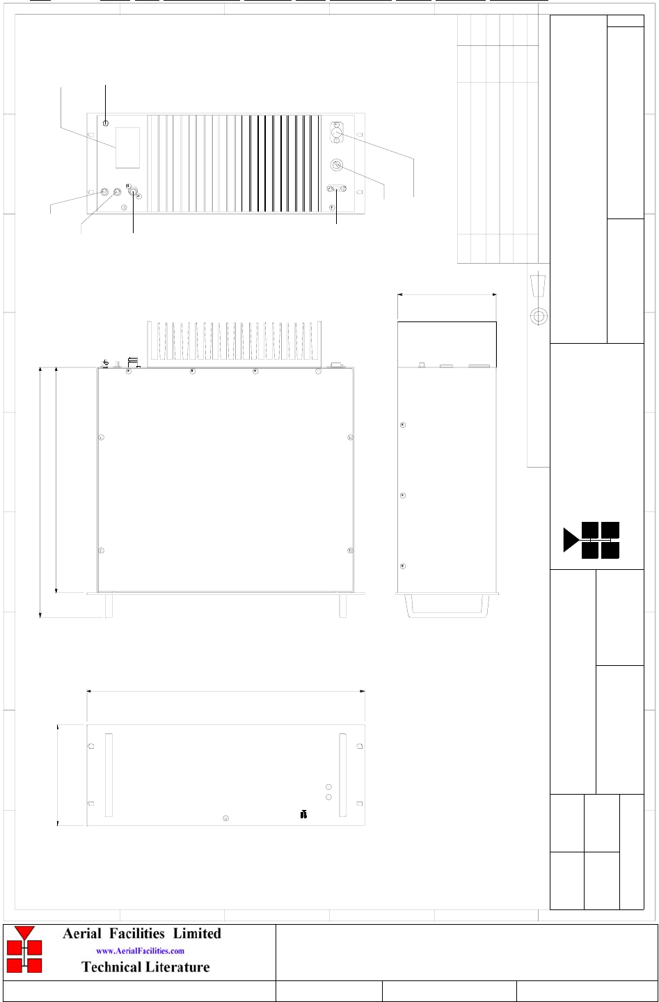
4.3 Drg. Nō. 50-063792, Base Side Duplex Shelf Outline Drawing
Lim ited
Ae ria l Fa c i litie s
177.50
443.00
400.00
171.50
482.60
BYDAT EDES CRIP TIO NNo
ISSUE
THIRD ANGL E PRO JECTION
12
3456789
A
B
C
D
E
F
1 23456789
A
B
C
D
E
F
Fax : 01494 777002
Tel : 01494 777000
Aerial Facilities Limited
THIS IS A PROPRIETARY DESIGN OF AERIAL FACILITIES L TD.
REP RO DUCT IO N O R USE O F THIS DESIG N BY O THERS IS
PERMISSIBLE O NL Y IF EXPRESSLY AUTHORISED IN WRITING
BY AERIAL FACIL ITIES LTD.
NO DECIM AL PL ACE ± 1 mm
ONE DECIMAL PL ACE ± 0.3mm
TWO DECIMAL PL ACES ± 0.1mm
AL L DIMENSIO NS ARE IN m m
UNL ESS OTHERWISE STATED
CHKD
DRAWN
APPD
DAT E
T O L ERANCES SCALE
England
CUST O MER DRAWING .No
TITLE
3
A
BASE SIDE DUPLEX/PA (4U CHASSIS)
OUTLINE DRAWING
50-063792
1:4
1A
MNR 22/09/03
PRODUCTION ISSUE
22/09/03
MNR
EARTH STUD
ATTENUATOR
SWITCHES
A (SMA)B (SMA)
C (SMA)
BASE 2 ('N'TYPE)
ALARM
FUSE T10A
DC INPUT
PART No : 50-063702
ALARM
POWER
RB BB
Denver Channelised CE
User/Maintenance Handbook
Handbook Nō.-50-063708HBKM Issue No:-2 Date:-03/11/2003 Page:-25 of 51
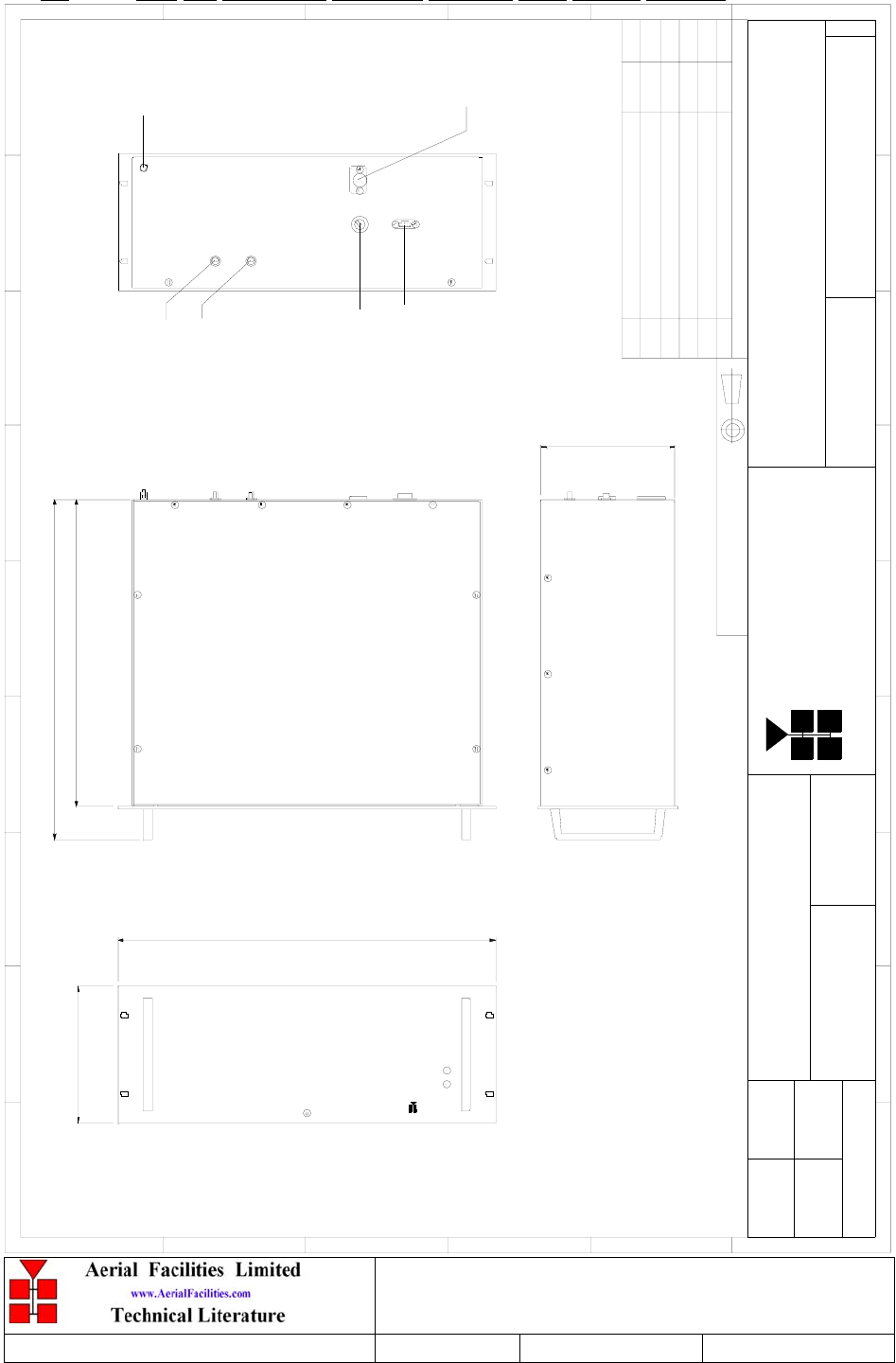
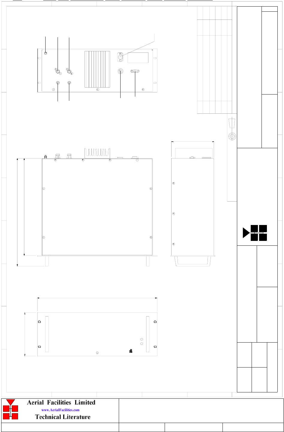
4.3 Drg. Nō. 50-063793, Downlink Channels Shelf Outline Drawing
Lim ited
Ae ria l Fa c i litie s
177.50
443.00
400.00
171.50
482.60
BYDAT EDES CRIP TIO NNo
ISSUE
THIRD ANGL E PRO JECTION
12
3456789
A
B
C
D
E
F
1 23456789
A
B
C
D
E
F
Fax : 01494 777002
Tel : 01494 777000
Aerial Facilities Limited
THIS IS A PROPRIETARY DESIGN OF AERIAL FACILITIES L TD.
REP RO DUCT IO N O R USE O F THIS DESIG N BY O THERS IS
PERMISSIBLE O NL Y IF EXPRESSLY AUTHORISED IN WRITING
BY AERIAL FACIL ITIES LTD.
NO DECIM AL PL ACE ± 1 mm
ONE DECIMAL PL ACE ± 0.3mm
TWO DECIMAL PL ACES ± 0.1mm
AL L DIMENSIO NS ARE IN m m
UNL ESS OTHERWISE STATED
CHKD
DRAWN
APPD
DAT E
T O L ERANCES SCALE
England
CUST O MER DRAWING .No
TITLE
3
A
DOWNLINK CHANNELS (4U CHASSIS)
OUTLINE DRAWING
50-063793
1:4
1A
MNR 22/09/03
PRODUCTION ISSUE
22/09/03
MNR
EARTH STUD
A (SMA)
D (SMA)
ALARM
FUSE T3.15A
DC INPUT
ALARM
POWER
PART No : 50-063703
RB BB
Denver Channelised CE
User/Maintenance Handbook
Handbook Nō.-50-063708HBKM Issue No:-2 Date:-03/11/2003 Page:-26 of 51
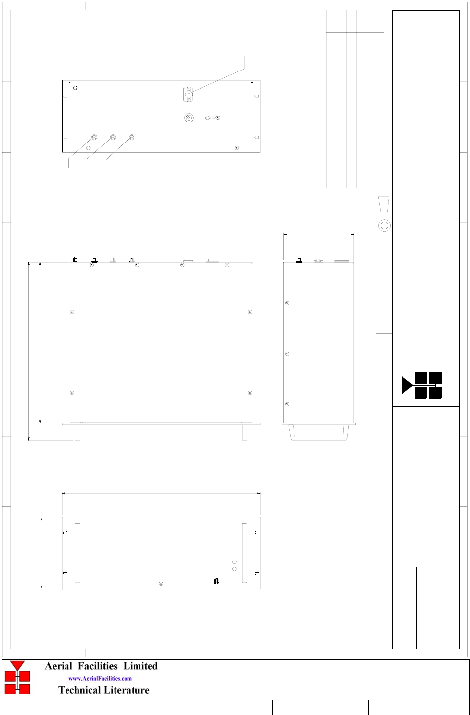
4.4 Drg. Nō. 50-063794, Uplink Channels Shelf Outline Drawing
Lim ited
Ae ria l Fa c i litie s
177.50
443.00
400.00
171.50
482.60
BYDAT EDES CRIP TIO NNo
ISSUE
THIRD ANGL E PRO JECTION
12
3456789
A
B
C
D
E
F
1 23456789
A
B
C
D
E
F
Fax : 01494 777002
Tel : 01494 777000
Aerial Facilities Limited
THIS IS A PROPRIETARY DESIGN OF AERIAL FACILITIES L TD.
REP RO DUCT IO N O R USE O F THIS DESIG N BY O THERS IS
PERMISSIBLE O NL Y IF EXPRESSLY AUTHORISED IN WRITING
BY AERIAL FACIL ITIES LTD.
NO DECIM AL PL ACE ± 1 mm
ONE DECIMAL PL ACE ± 0.3mm
TWO DECIMAL PL ACES ± 0.1mm
AL L DIMENSIO NS ARE IN m m
UNL ESS OTHERWISE STATED
CHKD
DRAWN
APPD
DAT E
T O L ERANCES SCALE
England
CUST O MER DRAWING .No
TITLE
3
A
UPLINK CHANNELS (4U CHASSIS)
OUTLINE DRAWING
50-063794
1:4
1A
MNR 22/09/03
PRODUCTION ISSUE
22/09/03
MNR
EARTH STUD
E (SMA)
F (SMA)
ALARM
FUSE T3.15A
DC INPUT
B (SMA)
ALARM
POWER
PART No : 50-063704
RB BB
Denver Channelised CE
User/Maintenance Handbook
Handbook Nō.-50-063708HBKM Issue No:-2 Date:-03/11/2003 Page:-27 of 51
4.5 Drg. Nō. 50-063795, Tunnel Side Duplexer Shelf Outline Drawing
Lim ited
Ae ria l Fa c i litie s
177.50
443.00
400.00
171.50
482.60
BYDAT EDES CRIP TIO NNo
ISSUE
THIRD ANGL E PRO JECTION
12
3456789
A
B
C
D
E
F
1 23456789
A
B
C
D
E
F
Fax : 01494 777002
Tel : 01494 777000
Aerial Facilities Limited
THIS IS A PROPRIETARY DESIGN OF AERIAL FACILITIES L TD.
REP RO DUCT IO N O R USE O F THIS DESIG N BY O THERS IS
PERMISSIBLE O NL Y IF EXPRESSLY AUTHORISED IN WRITING
BY AERIAL FACIL ITIES LTD.
NO DECIM AL PL ACE ± 1 mm
ONE DECIMAL PL ACE ± 0.3mm
TWO DECIMAL PL ACES ± 0.1mm
AL L DIMENSIO NS ARE IN m m
UNL ESS OTHERWISE STATED
CHKD
DRAWN
APPD
DAT E
T O L ERANCES SCALE
England
CUST O MER DRAWING .No
TITLE
3
A
TUNNEL SIDE DUPLEXER/PA (4U CHASSIS)
OUTLINE DRAWING
50-063795
1:4
1A
MNR 22/09/03
PRODUCTION ISSUE
22/09/03
MNR
EARTH STUD
ATTENUATOR
SWITCHES
D (SMA)
E (SMA)
LEAKY FEEDER
('N'TYPE)
ALARM
FUSE T10A
DC INPUT
ALARM
POWER
PART No : 50-063705
RB BB
Denver Channelised CE
User/Maintenance Handbook
Handbook Nō.-50-063708HBKM Issue No:-2 Date:-03/11/2003 Page:-28 of 51
4.6 Drg. Nō. 50-063796, UHF Simplex Shelf Outline Drawing
Lim ited
Ae ria l Fa c i litie s
177.50
443.00
400.00
171.50
482.60
BYDAT EDES CRIP TIO NNo
ISSUE
THIRD ANGL E PRO JECTION
12
3456789
A
B
C
D
E
F
1 23456789
A
B
C
D
E
F
Fax : 01494 777002
Tel : 01494 777000
Aerial Facilities Limited
THIS IS A PROPRIETARY DESIGN OF AERIAL FACILITIES L TD.
REP RO DUCT IO N O R USE O F THIS DESIG N BY O THERS IS
PERMISSIBLE O NL Y IF EXPRESSLY AUTHORISED IN WRITING
BY AERIAL FACIL ITIES LTD.
NO DECIM AL PL ACE ± 1 mm
ONE DECIMAL PL ACE ± 0.3mm
TWO DECIMAL PL ACES ± 0.1mm
AL L DIMENSIO NS ARE IN m m
UNL ESS OTHERWISE STATED
CHKD
DRAWN
APPD
DAT E
T O L ERANCES SCALE
England
CUST O MER DRAWING .No
TITLE
3
A
UHF SIMPLEX (4U CHASSIS)
OUTLINE DRAWING
50-063796
1:4
1A
MNR 22/09/03
PRODUCTION ISSUE
22/09/03
MNR
EARTH STUD
A (SMA)
D (SMA)
ALARM
FUSE T3.15A
DC INPUT
LEAKY FEEDER
('N'TY PE)
BASE 1
('N'TYPE)
ALARM
POWER
PART No : 50-063706
RB BB
Denver Channelised CE
User/Maintenance Handbook
Handbook Nō.-50-063708HBKM Issue No:-2 Date:-03/11/2003 Page:-29 of 51
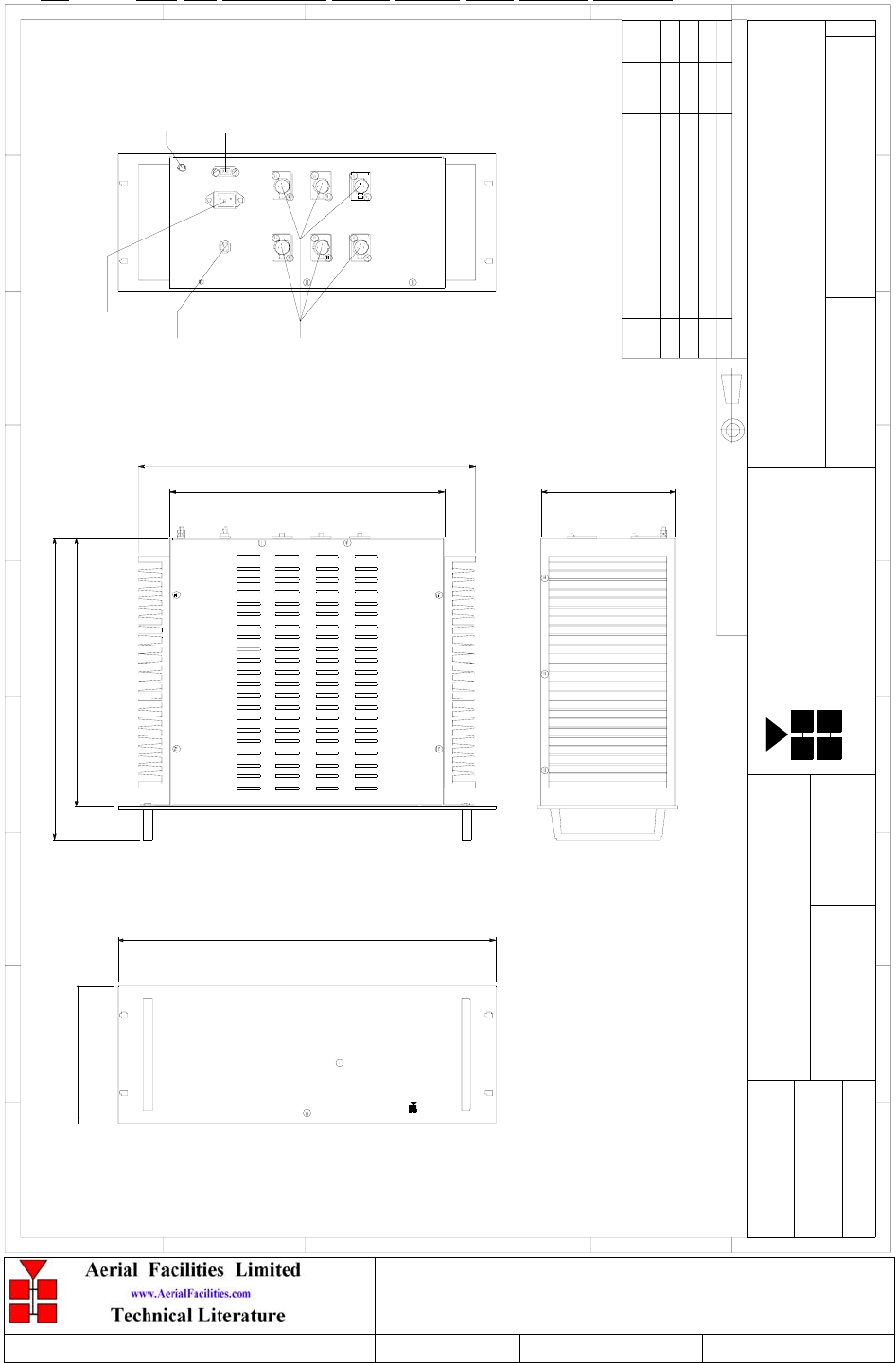
4.7 Drg. Nō. 50-063797, Power Supply Shelf Outline Drawing
Lim ited
Ae ria l Fa c i litie s
177.50
393.00
350.00
350.00
171.50
482.60
BYDAT EDES CRIP TIO NNo
ISSUE
THIRD ANGL E PRO JECTION
12
3456789
A
B
C
D
E
F
1 23456789
A
B
C
D
E
F
Fax : 01494 777002
Tel : 01494 777000
Aerial Facilities Limited
THIS IS A PROPRIETARY DESIGN OF AERIAL FACILITIES L TD.
REP RO DUCT IO N O R USE O F THIS DESIG N BY O THERS IS
PERMISSIBLE O NL Y IF EXPRESSLY AUTHORISED IN WRITING
BY AERIAL FACIL ITIES LTD.
NO DECIM AL PL ACE ± 1 mm
ONE DECIMAL PL ACE ± 0.3mm
TWO DECIMAL PL ACES ± 0.1mm
AL L DIMENSIO NS ARE IN m m
UNL ESS OTHERWISE STATED
CHKD
DRAWN
APPD
DAT E
T O L ERANCES SCALE
England
CUST O MER DRAWING .No
TITLE
3
A
POWER SUPPLY UNIT (4U CHASSIS)
OUTLINE DRAWING
50-063797
1:4
1A
MNR 22/09/03
PRODUCTION ISSUE MNR
22/09/03
ON
OFF
430.00
MAINS
TRIP
SWITCH
110/125V AC
INPUT
EARTH STUD
ALARMS
24V DC
OUTP UT
PART No : 50-063707
RB BB
Denver Channelised CE
User/Maintenance Handbook
Handbook Nō.-50-063708HBKM Issue No:-2 Date:-03/11/2003 Page:-30 of 51
5. SUB-UNIT MODULES
5.1 UHF Duplex Shelf 50-063702
5.1.1 Bandpass Filter (02-010701)
5.1.1.1 Description
The bandpass filters are multi-section designs with a bandwidth dependent upon the
passband frequencies, (both tuned to customer requirements). The response shape is basically
Chebyshev with a passband design ripple of 0.1dB. The filters are of combline design, and
are carefully aligned during manufacture in order to optimise the insertion loss, VSWR and
intermodulation characteristics of the unit. The tuned elements are silver-plated to reduce
surface ohmic losses and maintain a good VSWR figure and 50Ω load at the input and output
ports.
Being passive devices, the bandpass filters should have an extremely long operational life
and require no maintenance. Should a filter be suspect, it is usually most time efficient to
replace the module rather than attempt repair or re-tuning.
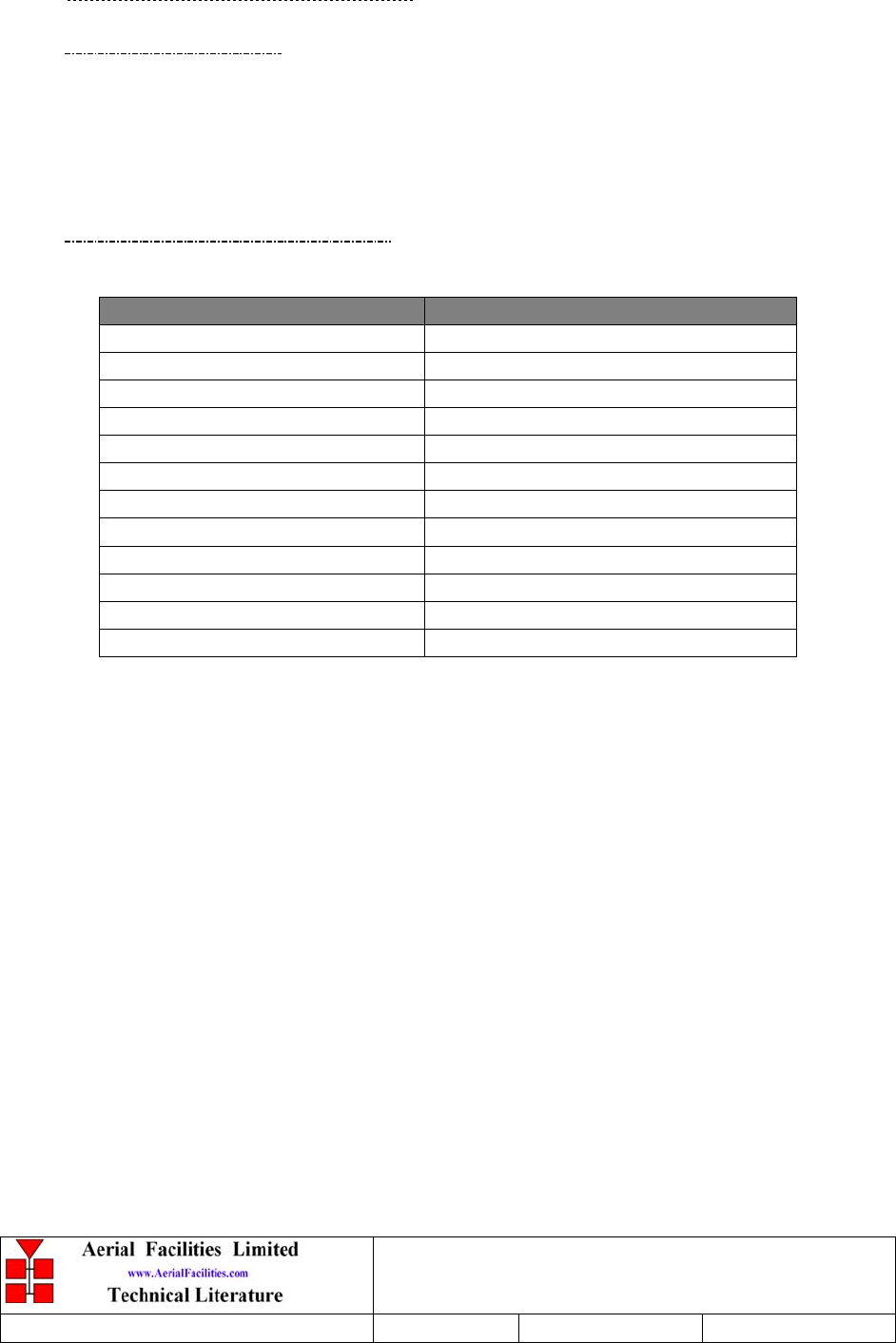
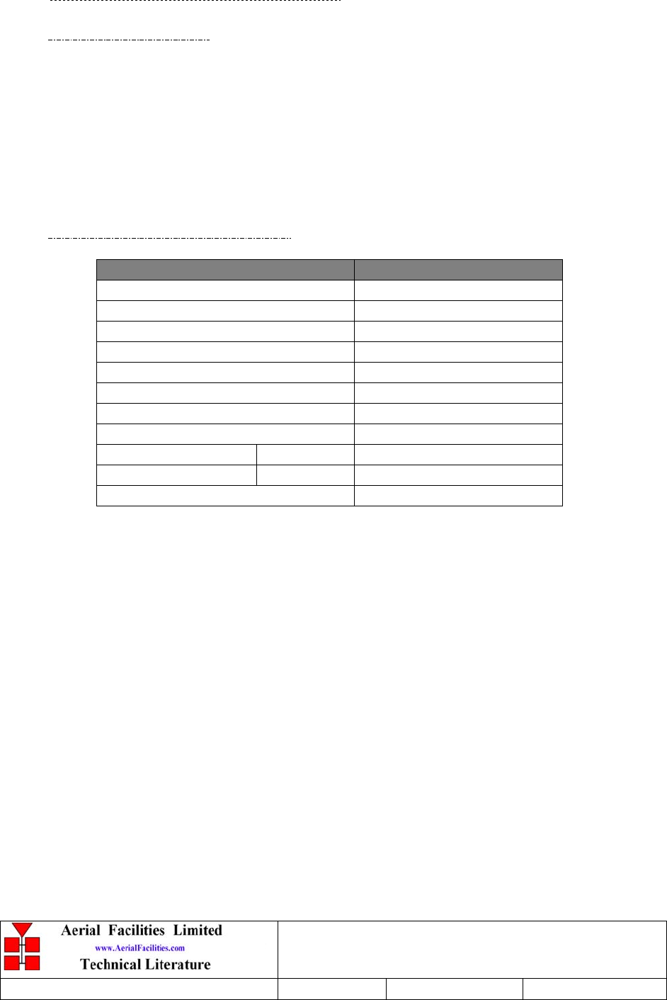
5.1.1.2 Technical Specification
PARAMETER SPECIFICATION
Response Type: Chebyshev
457.0-458.5MHz (Downlink)
Frequency Range: 452.0-453.5MHz (Uplink)
Bandwidth: 1.5 MHz
Number of Sections: 5
Insertion Loss: 1.7 dB (typical)
VSWR: better than 1.2:1
Connectors: SMA
Power Handling: 100W max
operation: -30°C to +60°C
Temperature range storage: -40°C to +70°C
Weight: 3 kg (typical)
Denver Channelised CE
User/Maintenance Handbook
Handbook Nō.-50-063708HBKM Issue No:-2 Date:-03/11/2003 Page:-31 of 51
5.1.2 3dB UHF Splitter (05-002603)
5.1.2.1 Description
The 3dB Splitter/Combiner used is a device for accurately matching two or more RF signals
to single or multiple ports, whilst maintaining an accurate 50Ω load to all inputs/outputs
over the specified frequency range and ensuring that the VSWR and insertion losses are kept
to a minimum.
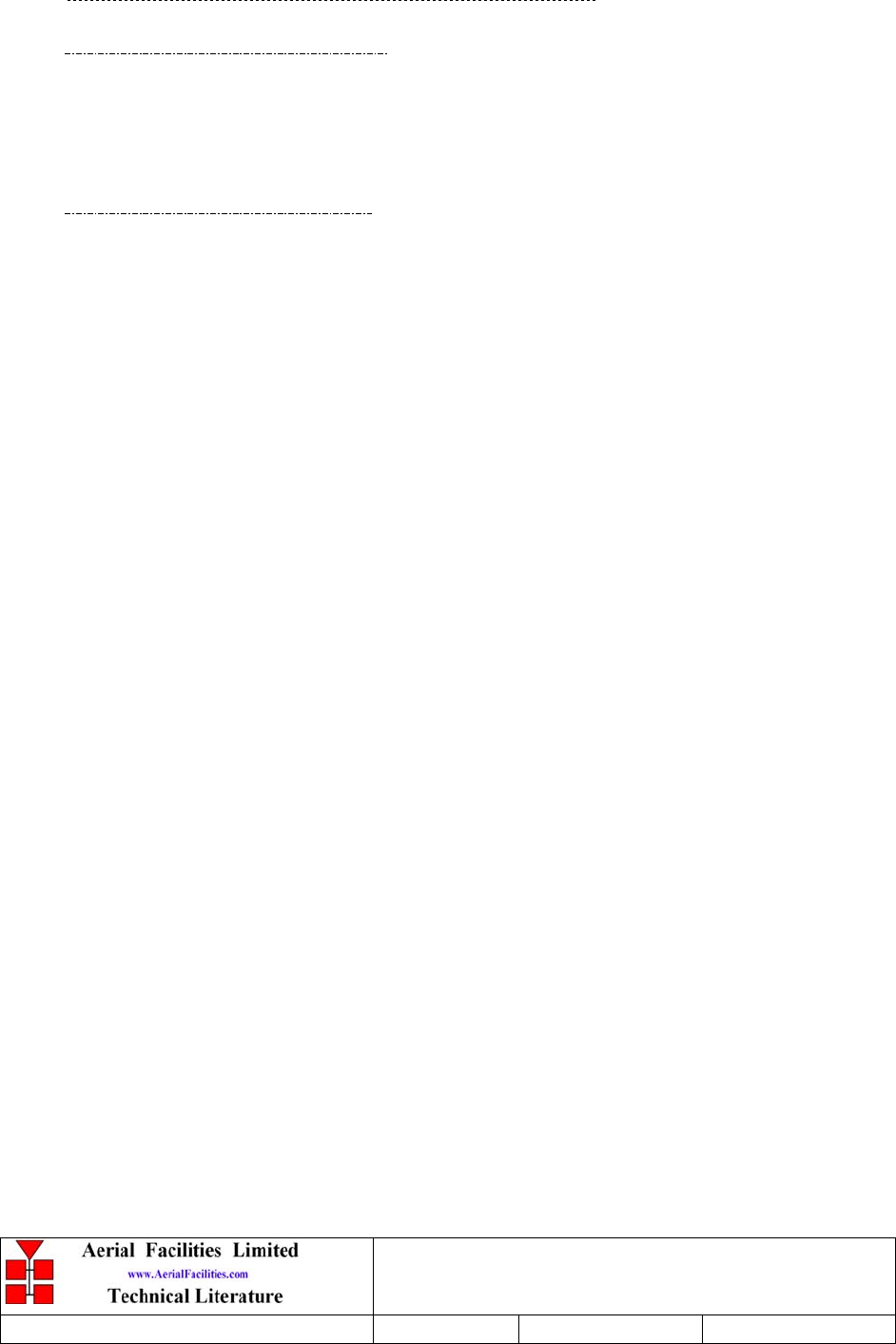
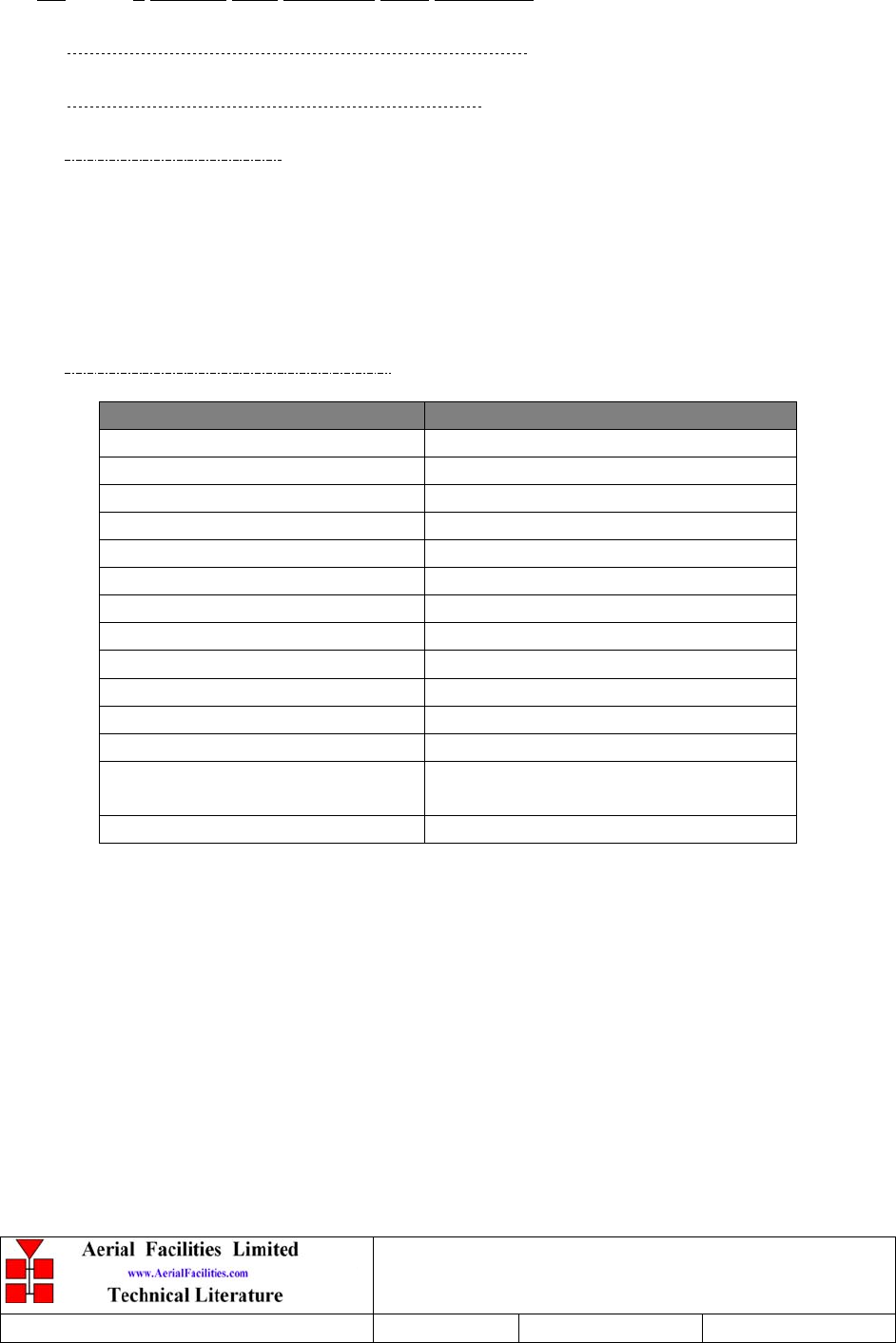
5.1.2.2 Technical Specification
PARAMETER SPECIFICATION
Frequency Range: 380 - 520 MHz
Bandwidth: 140 MHz
Inputs: 1
Outputs: 2
Insertion Loss: 3.5 dB (typical)
Isolation: >18 dB
Return Loss (VSWR) – Input: Better than 1.3:1
Impedance: 50 ς
Power Rating – Splitter: 20 Watts
Power Rating – Combiner: 0.5 Watt
Connectors: SMA female
Weight: 200 gm (approximately)

Denver Channelised CE
User/Maintenance Handbook
Handbook Nō.-50-063708HBKM Issue No:-2 Date:-03/11/2003 Page:-32 of 51
5.1.3 Ferrite Isolator (08-930003)
5.1.3.1 Description
The purpose of fitting an isolator to the output of a transmitter in a multi-transmitter
environment is such that each output is afforded a degree of isolation from every other.
Were this not to be the case, two simultaneous transmissions could interfere to create
intermodulation products, especially in the non-linear power amplifier output stages of
the transmitters. Whilst this effect would not affect the intelligibility of the two original
transmissions, a further two new transmissions would be created which could themselves
cause interference to third party users. In this case it is to isolate the duplex and simplex
uplink power amplifiers from inter-modulating each other.
A ferrite-isolator, (or junction circulator, as it is sometimes known) generally consists of
several major components; for example a ferrite region, a magnetic circuit and matching
circuitry which can form a three port isolator.
The ferrite isolator is a ferro-magnetic device, which has directional properties. In the
forward direction, RF arriving at the input is passed to the output with minimal
attenuation. In the reverse direction, RF arriving at the output due to reflected power
from a badly matched load, or due to coupling with another transmitter, is routed into an
RF load where it is absorbed. The isolator therefore functions to prevent reflected RF
energy reaching the power amplifier where it could cause intermodulation products or
premature device failure.
Ferrite materials form the active part of the junction in which the actual circulation signal
flow occurs. When a signal encounters a ferrite disk (e.g. port l) biased with a magnetic
field, it divides and part of the signal flows in a clockwise direction, while a portion of
the signal travels in the counter-clockwise direction, each with a different velocity. The
combined effects of the two rotating signals, create a standing wave around the perimeter
of the ferrite disk. By choosing the proper value of the ferrite’s magnetisation and the
magnetic field, the standing wave can be made to create a voltage null at port 3, such that
no power is transferred to it and a peak voltage at port 2, transferring maximum power to
it from port l. If a termination is placed on port 3 to absorb the signal flow in the reverse
direction the device functions as an isolator.
Denver Channelised CE
User/Maintenance Handbook
Handbook Nō.-50-063708HBKM Issue No:-2 Date:-03/11/2003 Page:-33 of 51
5.1.4 ¼Watt 0- -30dB Switched Attenuator (10-000701)
5.1.4.1 General Application
In many practical applications for Cell Enhancers etc., the gain in each path is found to be
excessive. Therefore, provision is made within the unit for the setting of attenuation in
each path, to reduce the gain.
5.1.4.2 Switched Attenuators
The AFL switched attenuators are available in two different types; 0 – 30dB in 2 dB steps
(as in this case), or 0 – 15dB in 1 dB steps. The attenuation is simply set using the four
miniature toggle switches on the top of each unit. Each switch is clearly marked with the
attenuation it provides, and the total attenuation in line is the sum of the values switched
in. They are designed to maintain an accurate 50Ω impedance over their operating
frequency at both input and output.
Denver Channelised CE
User/Maintenance Handbook
Handbook Nō.-50-063708HBKM Issue No:-2 Date:-03/11/2003 Page:-34 of 51
5.1.5 Low Noise Amplifiers (11-006102, 11-007302 & 11-007402)
5.1.5.1 Description
The low noise amplifiers used are double stage solid-state low-noise amplifiers. 11-
006102 is a low noise amplifier with a 1Watt power device in its final stage, enabling it to
be used as a driver for the 20W power amplifier. Class A circuitry is used in the units to
ensure excellent linearity over a very wide dynamic range. The two active devices are
very moderately rated to provide a long trouble-free working life. There are no
adjustments on these amplifiers, and in the unlikely event of failure the entire amplifier
should be replaced.
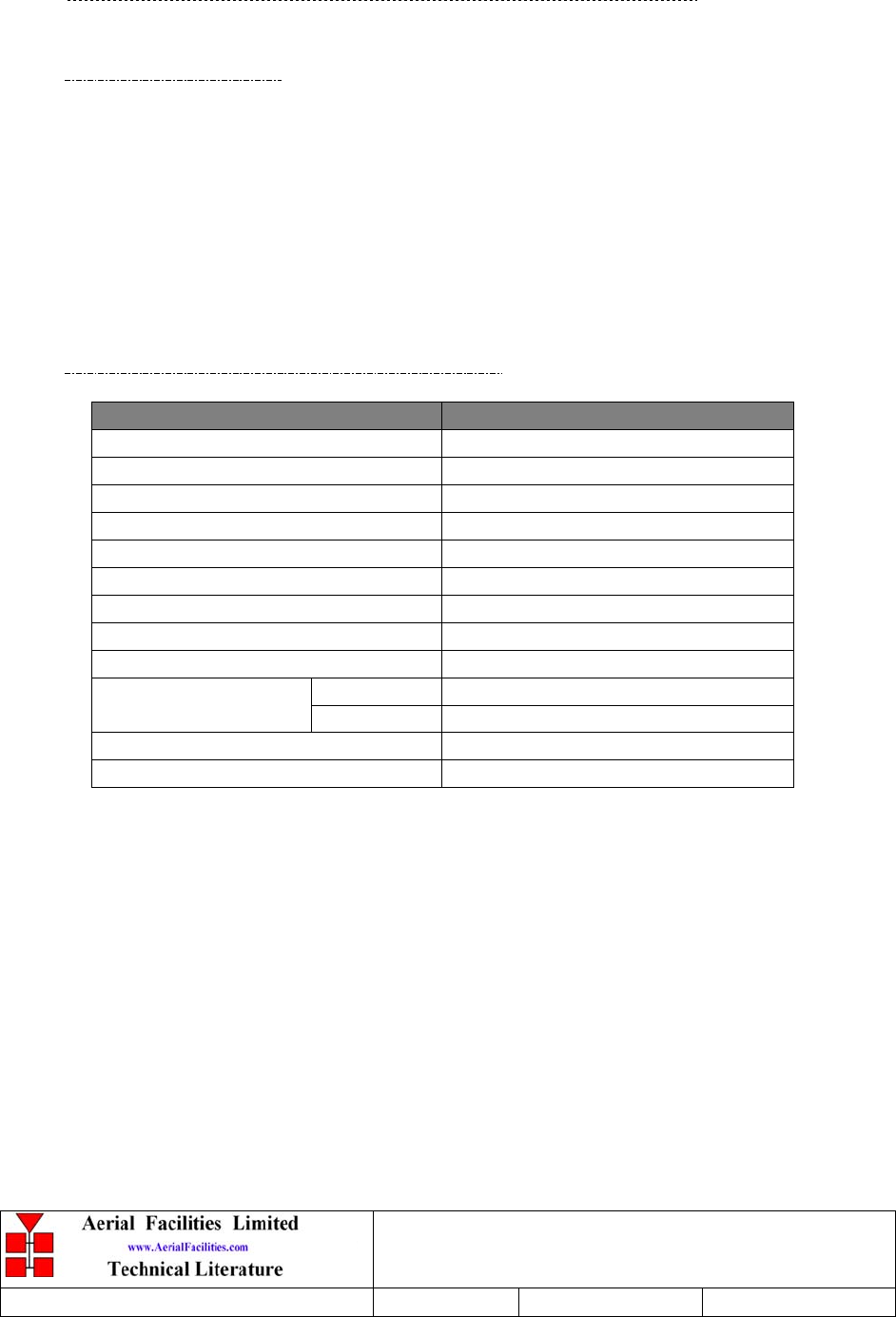
5.1.5.2 Technical Specification, 11-007302
PARAMETER SPECIFICATION
Frequency range: 380-500MHz
Bandwidth: <140MHz
Gain: 20-22dB
1dB Compression Point: +23.5dB (typical)
3rd order intercept: +36dB (typical)
Input/Output return loss: >20dB
Noise figure: <1.3dB
Connectors: SMA female
Supply: 200-230mA @ 24V DC
operational: -30°C to +60°C
Temperature range: storage: -30°C to +70°C
Weight: <300gm
Size: 90 x 55 x 30.2mm (case only)
Denver Channelised CE
User/Maintenance Handbook
Handbook Nō.-50-063708HBKM Issue No:-2 Date:-03/11/2003 Page:-35 of 51
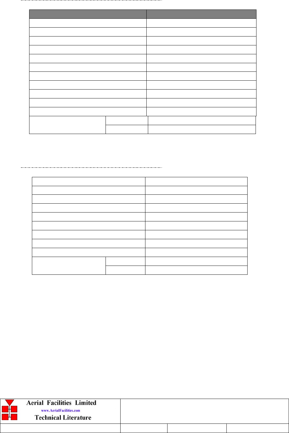
5.1.5.3 Technical Specification, 11-007402
PARAMETER SPECIFICATION
Frequency range: 380-500MHz
Bandwidth: <140MHz
Gain: 30-32dB
1dB Compression Point: +22dBm (typical)
3rd order intercept: +34-35dBm (typical)
Input/Output return loss: >20dB
Noise figure: <1.3dB
Connectors: SMA female
Supply: 300-330mA @ 24V DC
Weight: <300gm
Size: 90 x 55 x 30.2mm (case only)
operation: -30°C to +60°C
Temperature range storage: -40°C to +70°
5.1.5.4 Technical Specification, 11-006102
Frequency range: 380-500MHz
Bandwidth: <150MHz
Gain: 15dB (typical)
1dB compression point: +31dBm
IP3: +46dBm
I/O return loss: >18dB
Noise figure: <1.3dB
Supply requirement: 10 – 24V, DC
Consumption: 510-540mA @ (10 – 24V)
operation: -30°C to +60°C
Temperature range storage: -40°C to +70°
Denver Channelised CE
User/Maintenance Handbook
Handbook Nō.-50-063708HBKM Issue No:-2 Date:-03/11/2003 Page:-36 of 51
5.1.6 20W Power Amplifier (12-016301)
5.1.6.1 Description
This amplifier is a Class A 20W power amplifier from 380MHz to 470MHz in a 1 stage
balanced configuration. It demonstrates a very high linearity and a very good input/output
return loss. A built in a Current Fault Alarm Function monitors DC conditions to both
transistor collectors and gives an alarm upon bias change.
Its housing is a machined aluminium case (Alocrom 1200 finish) with SMA connectors
for the RF input/output and a D-Type connector for the power supply and the Current
Fault Alarm Function.
5.1.6.2 Technical Specification
PARAMETER SPECIFICATION
Frequency range: 380-470MHz
Small signal gain: 23dB
Gain flatness: ±1.7dB
I/O Return loss: >18dB
1dB compression point: +43dBm
OIP3: +55dBm
Supply voltage: 24V DC
Supply current: 3.8Amps (typical)
Temperature range operational: -30°C to +60°C
storage: -40°C to +70°C
Weight: <2kg (no heatsink)
Denver Channelised CE
User/Maintenance Handbook
Handbook Nō.-50-063708HBKM Issue No:-2 Date:-03/11/2003 Page:-37 of 51
5.2 5 Channel UHF Downlink Shelf 50-063703
5.2.1 3dB Splitter 905-002603) See section 5.1.2
5.2.2 3 Way Splitter/Combiner (05-003803)
5.2.2.1 Description
The 3 way Splitter/Combiner used is a ‘Zinger’ type design for accurately matching three
RF signals to a single port, whilst maintaining an accurate balance between ports, and
ensuring that the VSWR and insertion losses attain the best possible specification. They are
specialist passive devices and must be replaced in the unlikely event of failure.
5.2.2.2 Technical Specification
PARAMETER SPECIFICATION
Frequency Range: 380 - 520 MHz
Bandwidth: 140 MHz (typical)
Inputs: 3
Outputs: 1
Insertion Loss: 5.2 dB (typical)
Isolation: >18 dB
Return Loss (VSWR) – Input: Better than 1.35:1
Return Loss (VSWR) – Output: Better than 1.35:1
Impedance: 50 ς
Power Rating – Splitter: 20 Watts
Power Rating – Combiner: 0.5 Watt
Connectors: SMA female
Size: 54 x 44 x 21 mm (including
connectors)
Weight: 200 gm (approximately)
Denver Channelised CE
User/Maintenance Handbook
Handbook Nō.-50-063708HBKM Issue No:-2 Date:-03/11/2003 Page:-38 of 51
5.2.3 Dual DC/DC Converter (13-001803)
5.2.3.1 Description
This unit is employed where it is necessary to derive two fixed voltage power supply rails
from some higher voltage. Typically it is used to derive 5, 8, 12 or 15V from a 24V input.
The circuit is based upon a pair of LM257 series variable voltage regulators (LM2576, 12
& 15V & LM2575, 5V), which are each capable of supplying an absolute maximum of
1.5A output current. Note that at full output current, the dissipation of the device must
remain within design limits, bearing in mind the voltage which is being dropped across it.
The maximum allowable dissipation will also depend on the efficiency of the heatsink on
which the device is mounted.
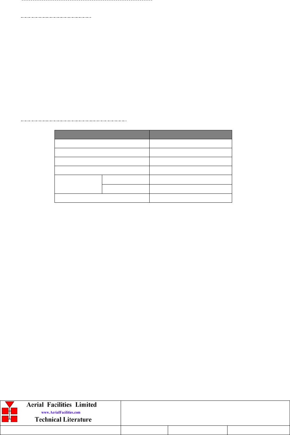
5.2.3.2 Technical Specification
PARAMETER SPECIFICATION
Operating Voltage: 21 – 27V DC
Output Voltage: 12V & 12V (typical)
Output Current: 1.0A (maximum per o/p)
Connections: Screw Terminal Block
operational: -30ΒC to +60ΒC
Temperature
Range storage -40ΒC to +70ΒC
PCB Size: 85 x 63mm

Denver Channelised CE
User/Maintenance Handbook
Handbook Nō.-50-063708HBKM Issue No:-2 Date:-03/11/2003 Page:-39 of 51
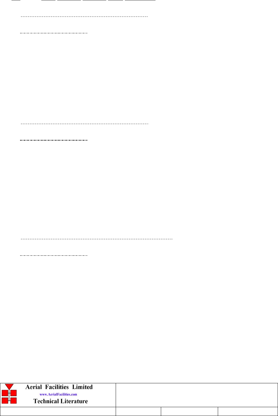
5.2.4 Channel Selective Module (17-003006)
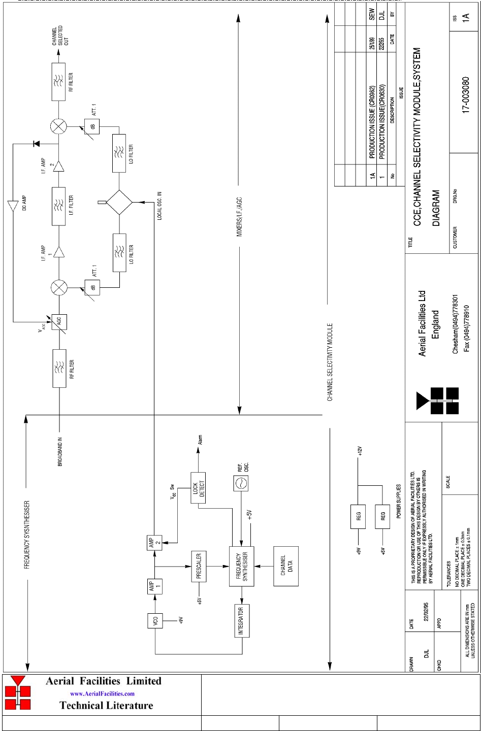
5.2.4.1 Description
The channel selectivity module is employed when the Cell Enhancer requirement dictates
that very narrow bandwidths (single operating channels), must be selected from within
the operating passband. One channel selectivity module is required for each channel.
The Channel Selectivity Module is an Up/Down frequency converter that mixes the
incoming channel frequency with a synthesised local oscillator, so that it is down-
converted to an Intermediate Frequency (IF) in the upper HF range. An eight pole crystal
filter in the IF amplifier provides the required selectivity to define the operating passband
of the Cell Enhancer to a single PMR channel. The same local oscillator then converts the
selected IF signal back to the channel frequency.
Selectivity is obtained from a fixed bandwidth block filter operating at an intermediate
frequency (IF) in the low VHF range. This filter may be internal to the channel selectivity
module (Crystal or SAW filter) or an externally mounted bandpass filter, (LC or Helical
Resonator). Various IF bandwidths can therefore be accommodated. A synthesized Local
Oscillator is employed in conjunction with high performance frequency mixers, to
translate between the signal frequency and IF.
The operating frequency of each channel selectivity module is set by the programming of
channel selectivity module frequencies and is achieved digitally, via hard wired links,
banks of DIP switches, or via an onboard RS232 control module, providing the ability to
remotely set channel frequencies.
Automatic Level Control (ALC) is provided within each channel selectivity module such
that the output level is held constant for high level input signals. This feature prevents
saturation of the output mixer and of the associated amplifiers.
Alarms within the module inhibit the channel if the synthesised frequency is not locked.
The synthesiser will not usually go out of lock unless a frequency far out of band is
programmed.
The channel selectivity module is extremely complex and, with the exception of channel
frequency programming within the design bandwidth, it cannot be adjusted or repaired
without extensive laboratory facilities and the necessary specialised personnel. If a fault
is suspected with any channel selectivity module it should be tested by substitution and
the complete, suspect module should then be returned to AFL for investigation.
Denver Channelised CE
User/Maintenance Handbook
Handbook Nō.-50-063708HBKM Issue No:-2 Date:-03/11/2003 Page:-40 of 51
5.2.4.2 Drg. Nō. 17-003080, Generic Channel Module Block Diagram
Denver Channelised CE
User/Maintenance Handbook
Handbook Nō.-50-063708HBKM Issue No:-2 Date:-03/11/2003 Page:-41 of 51
5.2.5 12V Relay Board (20-001601)
5.2.5.1 Description
The General Purpose Relay Board allows the inversion of signals and the isolation of
circuits. It is equipped with two dual pole change-over relays RL1 and RL2, with
completely isolated wiring, accessed via screw terminals.
Both relays are provided with polarity protection diodes and diodes for suppressing the
transients caused by "flywheel effect" which can destroy switching transistors or induce
spikes on neighbouring circuits. It’s common use is to amalgamate all the alarm signals into
one, volts-free relay contact pair for the main alarm system.
Note that the board is available for different voltages (12 or 24V) depending on the type of
relays fitted at RL1 and RL2.
5.2.5.2 Technical Specification
PARAMETER SPECIFICATION
Operating voltage: 8 to 30V (floating earth)
Alarm Threshold: Vcc - 1.20 volt +15%
Alarm output relay contacts:
Max. switch current: 1.0Amp
Max. switch volts: 120Vdc/60VA
Max. switch power: 24W/60VA
Min. switch load: 10.0µA/10.0mV
Relay isolation: 1.5kV
Mechanical life: >2x10⁷ operations
Relay approval: BT type 56
Connector details: Screw terminals
operational: :-30°C to +60°C
Temperature range storage: :-40°C to +70°C
Denver Channelised CE
User/Maintenance Handbook
Handbook Nō.-50-063708HBKM Issue No:-2 Date:-03/11/2003 Page:-42 of 51
5.3 UHF Uplink 4 Channel Shelf 50-063704
5.3.1 Four Way Splitter (05-003401)
5.3.1.1 Description
The Splitter/Combiner used is a device for accurately matching two or more RF signals to
single or multiple ports, whilst maintaining an accurate 50Ω load to all inputs/outputs and
ensuring that the VSWR and insertion losses are kept to a minimum. Any unused ports
will be terminated with an appropriate 50Ω load.
5.3.1.2 Technical Specification 05-003401
PARAMETER SPECIFICATION
Frequency range: 70 – 250MHz
Bandwidth: 180MHz
Rejection: >14dB
Insertion loss: 6.5dB (in band, typical)
Connectors: SMA
Weight: <1.5kg
operational
:
-30ΒC to +60ΒC
Temperature
range: storage -40ΒC to +70ΒC
All other modules in this shelf are described elsewhere in this document.
5.4 UHF Duplex/PA Shelf 50-063705
All modules in this shelf are described elsewhere in this document.
Denver Channelised CE
User/Maintenance Handbook
Handbook Nō.-50-063708HBKM Issue No:-2 Date:-03/11/2003 Page:-43 of 51
5.5 UHF Simplex Channel Shelf 60-063706
5.5.1 Simplex Controller PCB (13-002811)
5.5.1.1 Description
The Simplex controller logic PCB monitors the receiver squelch output for a signal change
and activates the supply switching for either the uplink or down link path accordingly. In
normal operation, the low level Rx path is activated, any the associated Tx path is switched
off. When a signal is detected by the Rx Squelch module, the Rx squelch output goes low
(0v), which triggers the controller logic PCB. The PCB mutes the power supply to the
opposite path Rx LNA’s and switches on the power to the output power stage. In order to
prevent the power stage noise blocking the opposite path’s low level receiver, the power
amplifier is normally muted.
5.5.2 ALC Attenuator Module (17-001201)
5.5.2.1 Description
The AFL Automatic Gain Control system consists of two units, a detector/amplifier and an
attenuator. The detector/amplifier unit is inserted in the RF path on the output of the power
amplifier, and the attenuator is situated in the RF path between the 1st and 2nd stages of
amplification. However, in this case only the attenuator is employed as part of the simplex
control system
The attenuator comprises a 50Ω P.I.N diode, voltage-variable attenuator with a range of 3 to
30dB. The attenuation is controlled by a DC voltage which is derived in this instance from
the simplex controller board.
5.5.3 Simplex Squelch Controller PCB (17-002802)
5.5.3.1 Description
The difference in signal levels between the up and downlink paths means that the channel
modules would latch onto any signal in the band rather than a signal at the desired channel
frequency. This is achieved, in part, to having the simplex controller apply maximum
attenuation (via the AGC attenuator unit) to the downlink path, when the uplink is active.
All other modules in this shelf are described elsewhere in this document.
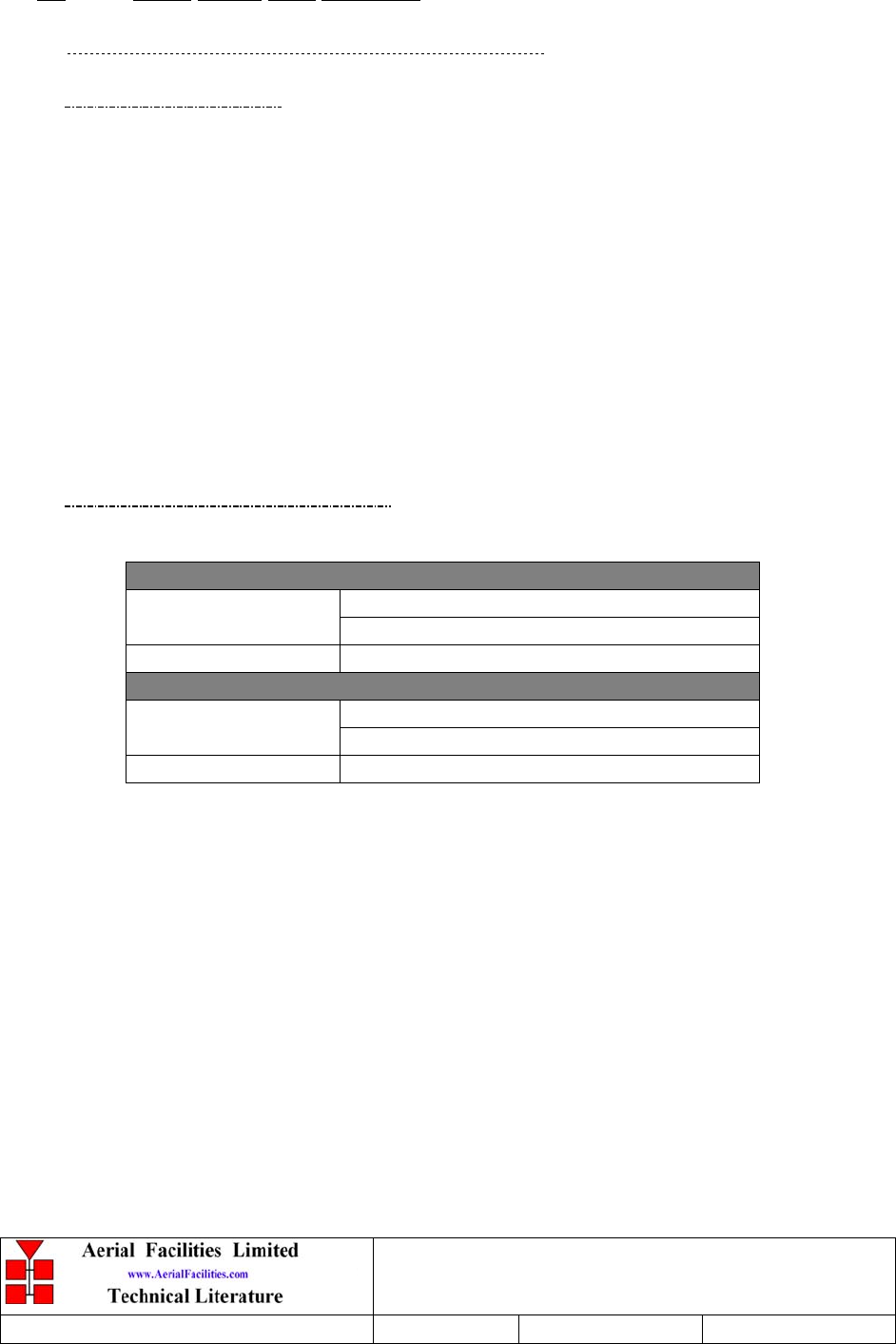
Denver Channelised CE
User/Maintenance Handbook
Handbook Nō.-50-063708HBKM Issue No:-2 Date:-03/11/2003 Page:-44 of 51
5.6 Power Supply Shelf 50-063707
5.6.1 24V, 400W Power Supply Pack (96-300054)
5.6.1.1 Description
The power supply unit is a switched-mode type capable of supplying 24V DC at 17.0Amps
continuously. Equipment of this type typically requires approximately 10.0 Amps at 24V
DC, so the PSU will be used conservatively ensuring a long operational lifetime.
No routine maintenance of the PSU is required. If a fault is suspected, then the output
voltage from the power supply may be measured on its output terminals. This is typically set
to 24.5V using the multi-turn potentiometer mounted close to the DC output studs on the
PSU PCB.
All the PSU’s used in AFL Cell Enhancers are capable of operation from either 110 or
220V nominal AC supplies. The line voltage is sensed automatically, so no adjustment or
link setting is needed by the operator.
5.6.1.1 Technical Specification
AC Input Supply
110 or 220V nominal
Voltages: 90 to 132 or 180 to 264V (absolute limits)
Frequency: 47 to 63Hz
DC Output Supply:
24V DC (nominal)
Voltage: 20 to 28V (absolute limits)
Maximum current: 17A
All other modules in this shelf are described elsewhere in this document.

Denver Channelised CE
User/Maintenance Handbook
Handbook Nō.-50-063708HBKM Issue No:-2 Date:-03/11/2003 Page:-45 of 51
6. INSTALLATION
6.1 Initial Installation Record
When this equipment is initially commissioned, please use the equipment set-up record sheet
(or similar) in Appendix A. This will help both the installation personnel and AFL should
these figures be needed for future reference or diagnosis.
Installation will be a matter of securing each shelf into its appropriate place in the rack
cabinet, connecting all the cables (RF, AC, DC and alarm) to their correct ports/connectors
and system testing (at the customer’s discretion) to prove the original specification. Power
should not be applied until all connections have been double-checked and verified.
Refer to the system/layout drawing(s) in section 4.0 for cabling details.

Denver Channelised CE
User/Maintenance Handbook
Handbook Nō.-50-063708HBKM Issue No:-2 Date:-03/11/2003 Page:-46 of 51
7. MAINTENANCE
7.1 General Procedures
7.1.1 Fault Finding
In the event that the performance of the system is suspect, a methodical and logical approach
to the problem will reveal the cause of the difficulty. The System consists of modules within
a wall mounted, environmentally protected enclosure
Transmissions from the main base stations are passed though the system to the mobile radio
equipment; this could be a handheld radio or a transceiver in a vehicle. This path is referred
to as the downlink. The return signal path from the mobile radio equipment to the base
station is referred to as the uplink.
The first operation is to check the alarms of each of the active units and determine that the
power supplies to the equipment are connected and active.
This can be achieved remotely (via CEMS, the RS232 Cell Enhancer Management System,
if fitted), or locally with the front panel LED’s. The green LED on the front panel should be
illuminated, while the red alarm indicator should be off.
If an Alarm is on, then that individual shelf must be removed and individually tested against
the original test specification.
The individual amplifier units within the shelf have a green LED showing through a hole in
their piggy-back alarm board, which is illuminated if the unit is working correctly.
If an amplifier is suspect, check the DC power supply to the unit. If no other fault is
apparent use a spectrum analyser to measure the incoming signal level at the input and then
after reconnecting the amplifier input, measure the output level. Consult with the system
diagram to determine the expected gain and compare result.
In the event that there are no alarms on and all units appear to be functioning it will be
necessary to test the system in a systematic manner to confirm correct operation.

Denver Channelised CE
User/Maintenance Handbook
Handbook Nō.-50-063708HBKM Issue No:-2 Date:-03/11/2003 Page:-47 of 51
7.1.2 Downlink
Confirm that there is a signal at the expected frequency and strength from the base station. If
this is not present then the fault may lay outside the system. To confirm this, inject a
downlink frequency signal from a known source at the master site BTS input and check for
output at the remote site feeder output.
If a signal is not received at the output it will be necessary to follow the downlink path
through the system to find a point at which the signal is lost. The expected downlink output
for the given input can be found in the end-to-end test specification.
7.1.3 Uplink
Testing the uplink involves a similar procedure to the downlink except that the frequencies
used are those transmitted by the mobile equipment.
7.1.4 Fault repair
Once a faulty component has been identified, a decision must be made on the appropriate
course to carry out a repair. A competent engineer can quickly remedy typical faults such as
faulty connections or cables. The exceptions to this are cable assemblies connecting
bandpass filter assemblies that are manufactured to critical lengths to maintain a 50-ohm
system. Care should be taken when replacing cables or connectors to ensure that items are of
the correct specification. The repair of component modules such as amplifiers and bandpass
filters will not usually be possible in the field, as they frequently require specialist
knowledge and test equipment to ensure correct operation. It is recommended that items of
this type are replaced with a spare unit and the faulty unit returned to AFL for repair.

Denver Channelised CE
User/Maintenance Handbook
Handbook Nō.-50-063708HBKM Issue No:-2 Date:-03/11/2003 Page:-48 of 51
7.1.5 Checking service
Following the repair of any part of the system it is recommended that a full end-to-end test is
carried out in accordance with the test specification and that the coverage is checked by
survey.
It is important to bear in mind that the system includes a radiating cable network and base
stations that may be faulty or may have been damaged.
7.1.6 Service Support
Advice and assistance with maintaining and servicing this system are available by contacting
Aerial Facilities Ltd.
7.2 Tools & Test Equipment
The minimum tools and test equipment needed to successfully service this AFL product are
as follows:-
Spectrum analyser: 100kHz to 2GHz (Dynamic range = 90dB).
Signal Generator: 30MHz to 2GHz (-120dBm to 0dBm o/p level).
Attenuator: 20dB, 10W, DC-2GHz, (N male – N female).
Test Antenna: Yagi or dipole for operating frequency.
Digital multi-meter: Universal Volt-Ohm-Amp meter.
Test cable x 2: N male – N male, 2M long RG214.
Test cable x 2: SMA male – N male, 1m long RG223.
Hand tools: Philips #1&2 tip screwdriver.
3mm flat bladed screwdriver.
SMA spanner and torque setter.
Denver Channelised CE
User/Maintenance Handbook
Handbook Nō.-50-063708HBKM Issue No:-2 Date:-03/11/2003 Page:-49 of 51
7.3 Care of Modules
7.3.1 General Comments
Many of the active modules contain semiconductor devices utilising MOS technology, which
can be damaged by electrostatic discharge. Correct handling of such modules is mandatory to
ensure their long-term reliability.
To prevent damage to a module, it must be withdrawn/inserted with care. The module may
have connectors on its underside, which might not be visible to the service operative.
7.3.2 Module Removal (LNA’s, general procedure):
The following general instructions should be followed to remove a module:
1 Remove power to the unit
2 Remove all visible connectors (RF, DC & alarm)
3 Release module retaining screws.
4 Slowly but firmly, pull the module straight out of its position. Take care not to twist/turn
the module during withdrawal. (When the module is loose, care may be needed, as there
may be concealed connections underneath).
7.3.3 Module Replacement (general):
1 Carefully align the module into its location then slowly push the module directly straight
into its position, taking care not to twist/turn it during insertion.
2 Reconnect all connectors, RF, alarm, power etc.,(concealed connectors may have to be
connected first).
3 Replace retaining screws (if any).
4 Double-check all connections before applying power.
7.3.4 Power Amplifiers
1) Remove power to the unit. (Switch off @ mains/battery, or remove DC in connector)
2) Remove alarm wires from alarm screw terminal block or disconnect multi-way alarm
connector.
3) Carefully disconnect the RF input and output coaxial connectors (usually SMA)
If alarm board removal is not required, go to step 5.
4) There is (usually) a plate attached to the alarm board which fixes it to the amplifier,
remove its retaining screws and the alarm board can be withdrawn from the amplifier in
its entirety. On certain types of amplifier the alarm board is not mounted on a dedicated
mounting plate; in this case it will have to firstly be removed by unscrewing it from the
mounting pillars, in most cases, the pillars will not have not have to be removed before
lifting the amplifier.
Denver Channelised CE
User/Maintenance Handbook
Handbook Nō.-50-063708HBKM Issue No:-2 Date:-03/11/2003 Page:-50 of 51
5) If the amplifier to be removed has a heatsink attached, there may be several different
ways it can have been assembled. The most commonly used method, is screws through
the front of the heatsink to threaded screw holes (or nuts and bolts), into the amplifier
within the main case. If the heatsink is mounted on the rear of the main case (e.g., against
a wall in the case of wall mounted enclosures), then the fixing method for the heatsink
will be from within the case, (otherwise the enclosure would have to be removed from the
wall in order to remove the heatsink).
When the heatsink has been removed, the amplifier may be unscrewed from the main
casing by its four corner fixings and gently withdrawn.
Fitting a new power amplifier module will be the exact reverse of the above.
Note: Do not forget to apply fresh heatsink compound to the heatsink/main case
joint and also between the amplifier and the main case.
7.3.5 Low Power Amplifier Replacement
1 Disconnect the mains power supply and disconnect the 24V dc supply connector for the
LPA.
2 Disconnect the RF input and output cables from the LPA.
3 Disconnect the alarm connector.
4 Remove the alarm monitoring wires from (D type connector) pins 9 and 10.
5 Remove the LPA module by removing the four retaining screws, replace with a new
LPA module and secure it with the screws.
6 Connect the RF cables to the LPA input and output connectors. Reconnect the wires to
the alarm board connector pins 9 and 10.
7 Reconnect the DC supply connector and turn the mains switch on.
Note: Tighten SMA connectors using only a dedicated SMA torque spanner. If
SMA connectors are over-tightened, irreparable damage will occur. . Do not use
adjustable pliers to loosen/tighten SMA connectors.
Also take care not to drop or knock the module as this can damage (or misalign in the
case of tuned passive modules) sensitive internal components. Always store the modules
in an environmentally friendly location
7.3.6 Module Transportation:
To maintain the operation, performance and reliability of any module it must be stored and
transported correctly. Any module not installed in a whole system must be kept in an anti-
static bag or container. These bags or containers are normally identified by being pink or
black, and are often marked with an ESD label. Any module sent back to AFL for
investigation/repair must be so protected. Please contact AFL’s quality department before
returning a module.
Denver Channelised CE
User/Maintenance Handbook
Handbook Nō.-50-063708HBKM Issue No:-2 Date:-03/11/2003 Page:-51 of 51
APPENDIX A INITIAL EQUIPMENT SET-UP CALCULATIONS
GENERAL INFORMATION
Site Name: Client Name:
Date: AFL Equip. Model Nō.
ANTENNA SYSTEMS
Model Gain Azimuth Comments
A - Service Antenna
B – Donor Antenna
Type Loss Length Comments
C – Service Feeder
D – Donor Feeder
INITIAL PARAMETERS
E – CE Output Power dBm
F – Antenna Isolation dB
G – Input signal level from donor BTS dBm
Operating Voltage V
DOWNLINK CALCULATIONS
Parameter Comments Value
Input signal level (G)dBm
CE max. o/p power (E)dBm
Gain setting E - G dB
Isolation required (Gain + 10dB) dB
Service antenna gain (A)dB
Service antenna feeder loss (C)dB
Effective radiated power (ERP) E+A-C dBm
Attenuator setting CE gain-gain setting dB
If the input signal level in the uplink path is known and steady, use the following calculation
table to determine the gain setting. If the CE features Automatic Gain Control the attenuator
should be set to zero and if not, then the attenuation setting for both uplink and downlink
should be similar.
UPLINK CALCULATIONS
Parameter Comments Value
Input signal level dBm
CE max. o/p power (E)dBm
Gain setting dB
Required isolation dB
Donor antenna gain (B)dB
Donor antenna feeder loss (D)dB
Effective radiated power (ERP)E+B-D dBm
Attenuator setting (CE gain-gain setting) dB