PBE Europe as Axell Wireless 50-0780-800 800MHz Cell Enhancer 50-078021 MV Upgrade User Manual Manual
Axell Wireless 800MHz Cell Enhancer 50-078021 MV Upgrade Manual
UserManual.wiki
>
PBE Europe as Axell Wireless
>
50-0780-800 User Manual
>
Manual
Contents
1.
User manual
2.
Manual
Manual
Navigation menu
Upload a User Manual
Namespaces
Wiki Guide
HTML
PDF
Info
Views
User Manual
Discussion / Help
Navigation
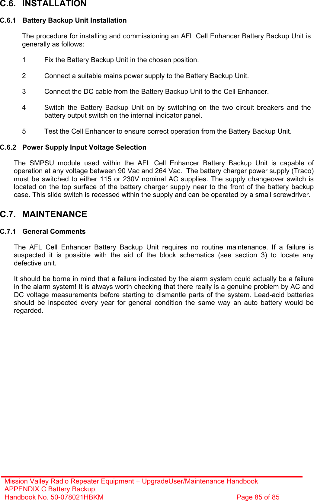
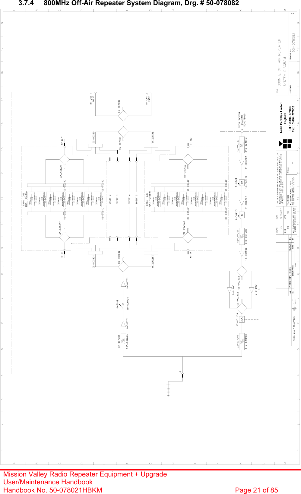
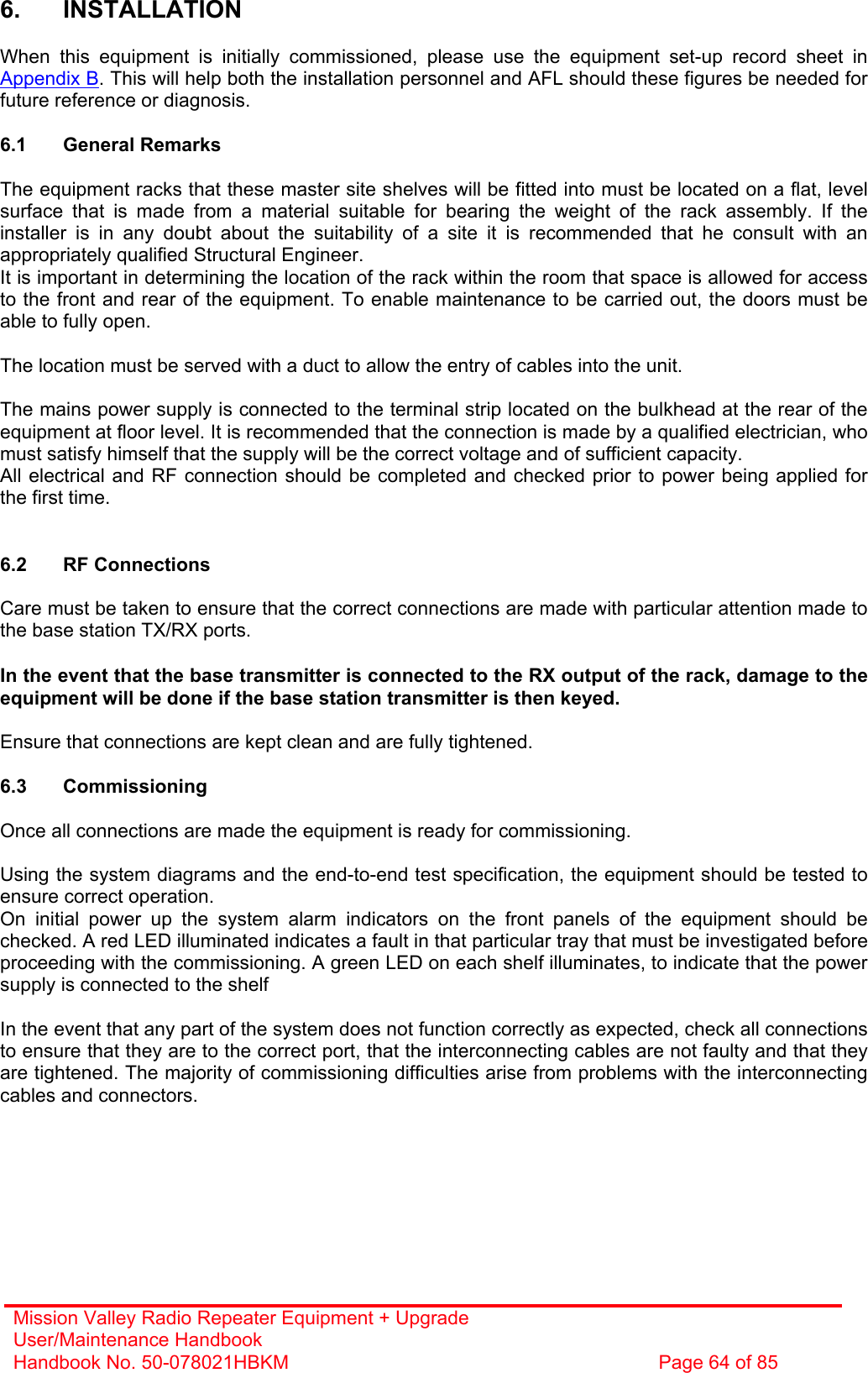
![Mission Valley Radio Repeater Equipment + Upgrade User/Maintenance Handbook Handbook No. 50-078021HBKM Page 20 of 85 3.7.3 Parts List AFL Part # Part Description Qty. 02-007201 900MHz 8POLE 10-20MHz B/W SMA 4 05-002602 900MHz SPLITTER/COMBINER, 20W 5 05-003801 3WAY GEN.SPLIT 900MHz GEN.ASS 4 10-000701 1/4W0-30dB SWITCHED ATTENUATOR 2 11-005902 900MHz LOW NOISE AMP WITH RELAY ASS 3 11-006702 GA 800-1000MHz LNA 29dB (WITH RELAY 4 12-018001 PA 800-960MHz 10W 30dB 2 14-000225 CASE RAIL LONG R.S.A./R.F.A. 4 17-001109 CE AGC UNIT LOG DET/AMP ASSY (12V) 1 17-001201 C/E AGC UNIT ATTENUATOR ASSY 1 20-001601 12V RELAY BOARD 1 50-012820 CCE RACK MOUNTED 8U CHASSIS 1 50-012822 CCE RACK MOUNTED LID 1 50-012825 CCE RACK MOUNTED HEATSINK BRACKET 4 50-027720 RACK MTD CHAN C.E. MODIFIED HEATSIN 2 80-090822 C/E 8U FRONT PANEL, AFL (RAL7035) 1 80-310420 BCC 400W POWER SUPPLY HEATSINK 1 91-030002 N ADAPTOR PANEL FEMALE:FEMALE 4 91-130005 SMA BULKHEAD ADAPTOR F/F 12 91-500025 3 PIN RIGHT ANGLE FREE PLUG NC-X 3 91-510003 3 PIN R.ANGLE FREE SOC.NC-X. 3 91-510004 3 PIN PNL.MOUNT SOCKET NC-X 3 91-510032 20A SOCKET CONTACT PIN 4 91-520001 PWR MAINS INL FIXED/SOLD.TERMS 1 91-520005 MAINS LEAD 1 91-520010 MAINS RETAINING CLIP 1 91-600007 'D' 9 WAY BLACK SHELL 8 91-600014 'D' 9 WAY SOCKET S/B (NON FILTERED) 7 91-600015 'D' 9 WAY PLUG S/B (NON FILTERED) 1 91-660001 2W5 MIXED D TYPE SOCKET (7 WAY) 2 96-110034 FUSE HOLDER 16-30A, 32mm BODY 3 96-300057 15V 27A PSU 400W (XP BCC) 1 96-700034 LED RED 5mm IP67 INTEGRAL RES. 24V 1 96-700035 LED GREEN 5mm IP67 INTEGRAL RES 24V 1 96-900018 AC TRIP SWITCH (5 AMP M.C.B.) 2 97-400005 HANDLE TYPE H6802 3U [ALLOY] 2 99-200008 DANGER HIGH VOLTAGE LABEL 2’ x 2' 1 99-200017 CAUTION HEAVY LABEL 75 x 55mm 2](https://usermanual.wiki/PBE-Europe-as-Axell-Wireless/50-0780-800.Manual/User-Guide-777495-Page-20.png)
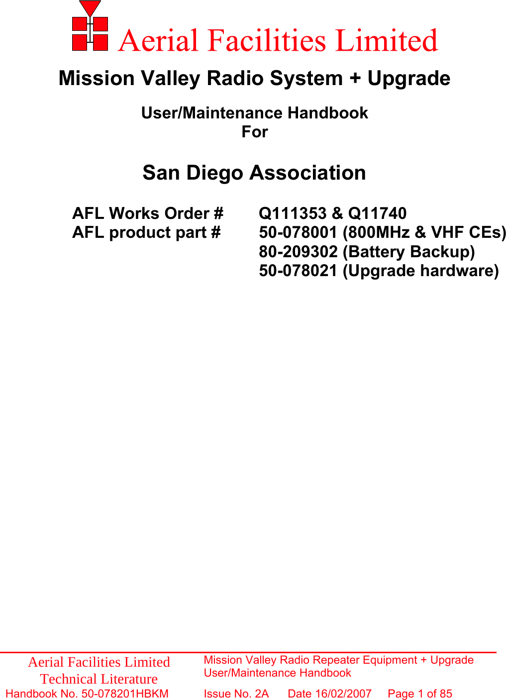
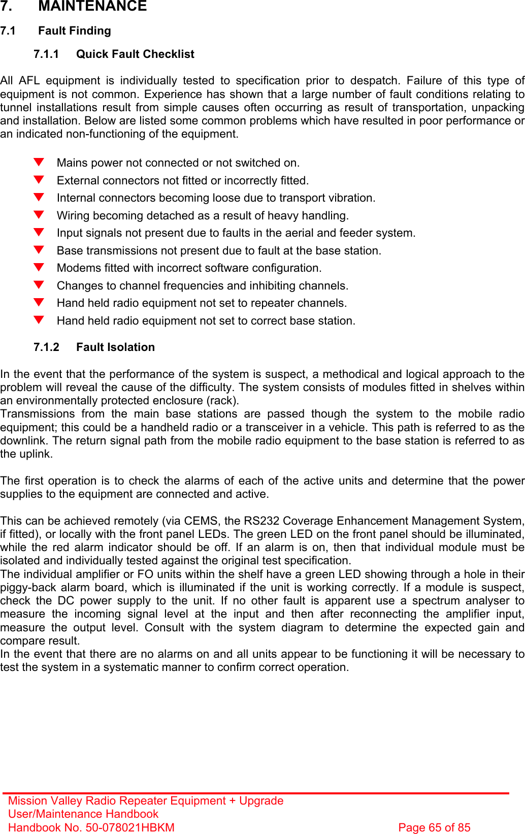
![Mission Valley Radio Repeater Equipment + Upgrade User/Maintenance Handbook Handbook No. 50-078021HBKM Page 30 of 85 3.9.3 Parts List AFL Part # Part Description Qty. 02-007201 900MHz 8POLE 10-20MHz B/W SMA 1 05-002602 900MHz SPLITTER/COMBINER, 20W 2 10-000901 SW. ATTENUATOR 0.25W 0-15dB 1 11-005802 900MHz DRIVER STAGE WITH RELAY 1 12-018002 PA 800-960MHz 20W CLASS A 2 14-000225 CASE RAIL LONG R.S.A./R.F.A. 2 50-012820 CCE RACK MOUNTED 8U CHASSIS 1 50-012822 CCE RACK MOUNTED LID 1 50-012825 CCE RACK MOUNTED HEATSINK BRACKET 4 50-027720 RACK MTD CHAN C.E. MODIFIED HEATSIN 2 80-090822 C/E 8U FRONT PANEL, AFL (RAL7035) 1 80-310420 BCC 400W POWER SUPPLY HEATSINK 1 91-030002 N ADAPTOR PANEL FEMALE:FEMALE 2 91-510032 20A SOCKET CONTACT PIN 4 91-520001 PWR MAINS INL FIXED/SOLD.TERMS 1 91-520005 MAINS LEAD 1 91-520010 MAINS RETAINING CLIP 1 91-600007 'D' 9 WAY BLACK SHELL 1 91-600014 'D' 9 WAY SOCKET S/B (NON FILTERED) 1 91-600015 'D' 9 WAY PLUG S/B (NON FILTERED) 1 91-660001 2W5 MIXED D TYPE SOCKET (7 WAY) 2 96-300057 15V 27A PSU 400W (XP BCC) 1 96-700034 LED RED 5mm IP67 INTEGRAL RES. 24V 1 96-700035 LED GREEN 5mm IP67 INTEGRAL RES 24V 1 96-900018 AC TRIP SWITCH (5 AMP M.C.B.) 1 97-400005 HANDLE TYPE H6802 3U [ALLOY] 2 99-200008 DANGER HIGH VOLTAGE LABEL 2’ x 2' 1 99-200017 CAUTION HEAVY LABEL 75 x 55mm 2](https://usermanual.wiki/PBE-Europe-as-Axell-Wireless/50-0780-800.Manual/User-Guide-777495-Page-30.png)
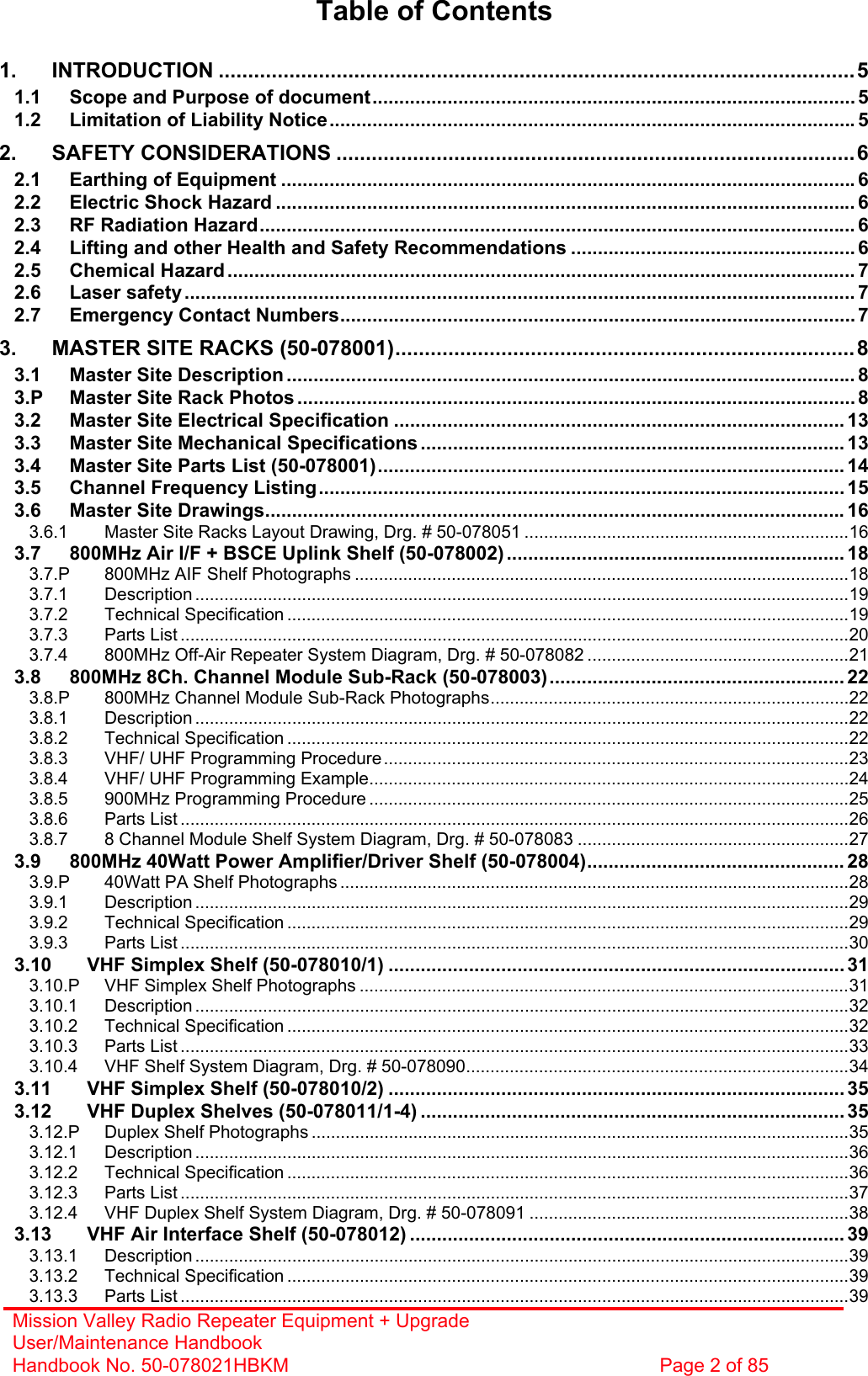
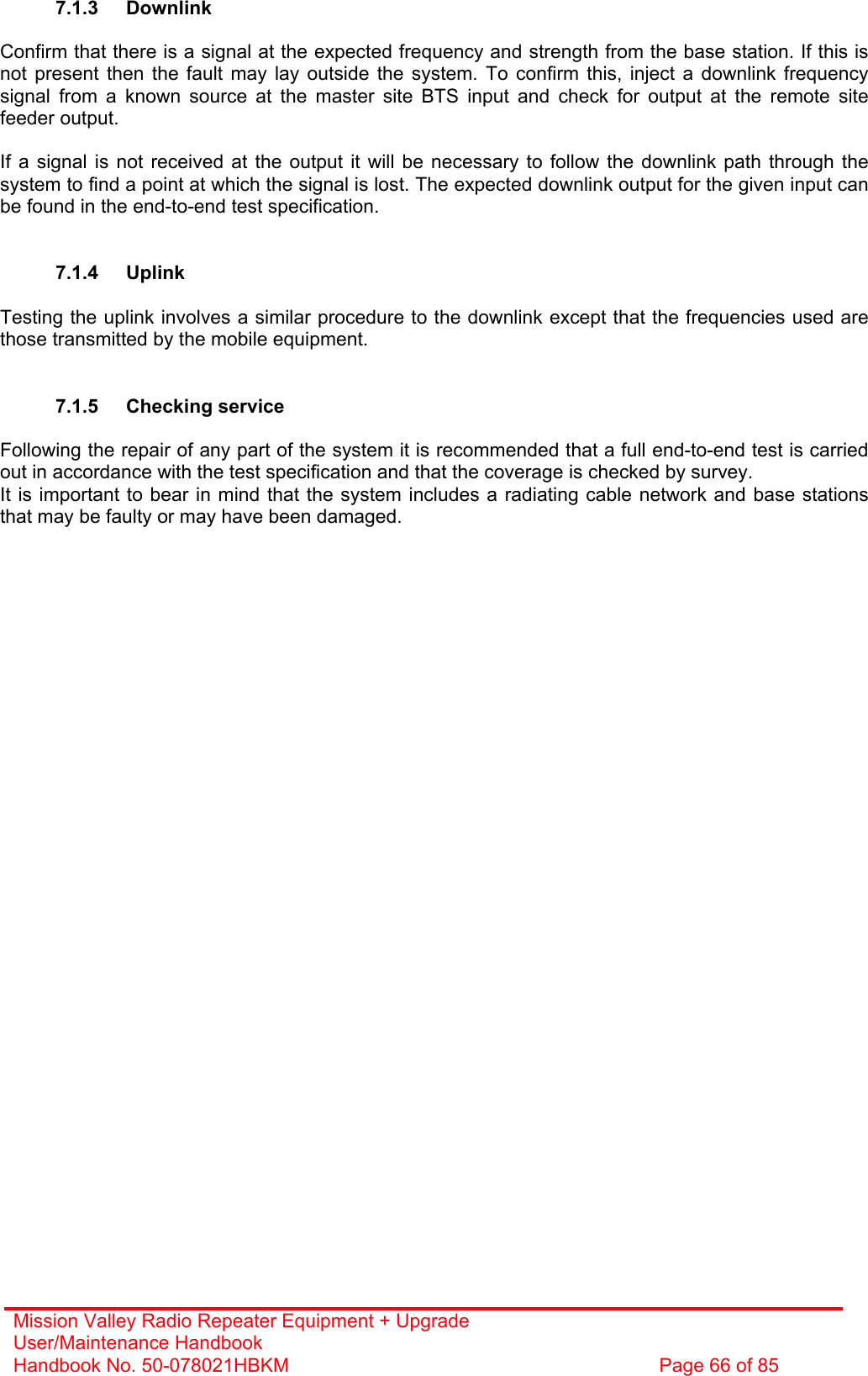
![Mission Valley Radio Repeater Equipment + Upgrade User/Maintenance Handbook Handbook No. 50-078021HBKM Page 33 of 85 3.10.3 Parts List AFL Part # Part Description Qty. 08-930002 2 PORT ISOLATOR 150-300MHz SMA 2 10-000901 SW. ATTENUATOR 0.25W 0-15dB 4 11-001202 10/600MHz LNA 24v SMA Alarm 7 12-002213 3 STAGE ALARM/SIMPLEXMUTE PCB SUB-ASS 2 12-002220 3 STAGE ALARM PCB COVER 2 12-002804 SINGLE CH. ALARM/SIMPLEX MUTE BOARD 7 12-002820 SINGLE CHANNEL ALARM COVER 7 12-004902 POWER AMP VHF 5W CLASS AB 2 13-001803 DUAL DC/DC CONVERTER 24V-12V 1A 1 13-001822 DC-DC CON 24V-5V/15V COVER 1 13-002811 SIMPLEX CONTROLLER PCB ASSEMBLY 2 17-001201 C/E AGC UNIT ATTENUATOR ASSY 4 17-002802 SIMPLEX C.E Rx/SQUELCH & AF (SMD) 2 17-009135 VHF 15Kstep CH MOD 15kHz 8P BW+IFRX 2 19-000826 2U,3U,4U 19" UNIT 400 DEEP LID 1 19-000921 3U 19" UNIT 400 DEEP CHASSIS + BKT 1 19-000924 3U 19" UNIT FRONT PANEL FAB 1 80-063920 HEATSINK 2U ASS140 (5W) 2 91-030002 N ADAPTOR PANEL FEMALE:FEMALE 4 91-500001 POWER PLG 3 PIN PNL.MOUNT NC-X 1 91-510003 3 PIN R.ANGLE FREE SOC.NC-X. 1 91-600001 'D'TYPE 9 WAY PLUG S/B TERM 1 91-600014 'D' 9 WAY SOCKET S/B (NON FILTERED) 2 91-620001 'D' 25 WAY SOCKET S/B TERM 2 91-700017 ICD 15 WAY 0.1' CONNECTOR 9 93-540035 1K3 0.25W 1% RES MRS25 M:F 2 *93-980109 161.295MHz CRYSTAL FILT FAN4M52500 4 **93-980112 160.530MHz CRYSTAL FILT FAN4M52500 4 96-110001 FUSE HOLDER 20 x 5mm6.3A 1 96-300014 PSU VOLTS ADJUSTER 2 96-700017 LED AMBER 5mm SEALED IP66 2 96-700034 LED RED 5mm IP67 INTEGRAL RES. 24V 1 96-700035 LED GREEN 5mm IP67 INTEGRAL RES 24V 1 97-400005 HANDLE TYPE H6802 3U [ALLOY] 2 * = Frequency selective crystal (50-078010/1 shelf) ** = Frequency selective crystal (50-078010/2 shelf)](https://usermanual.wiki/PBE-Europe-as-Axell-Wireless/50-0780-800.Manual/User-Guide-777495-Page-33.png)
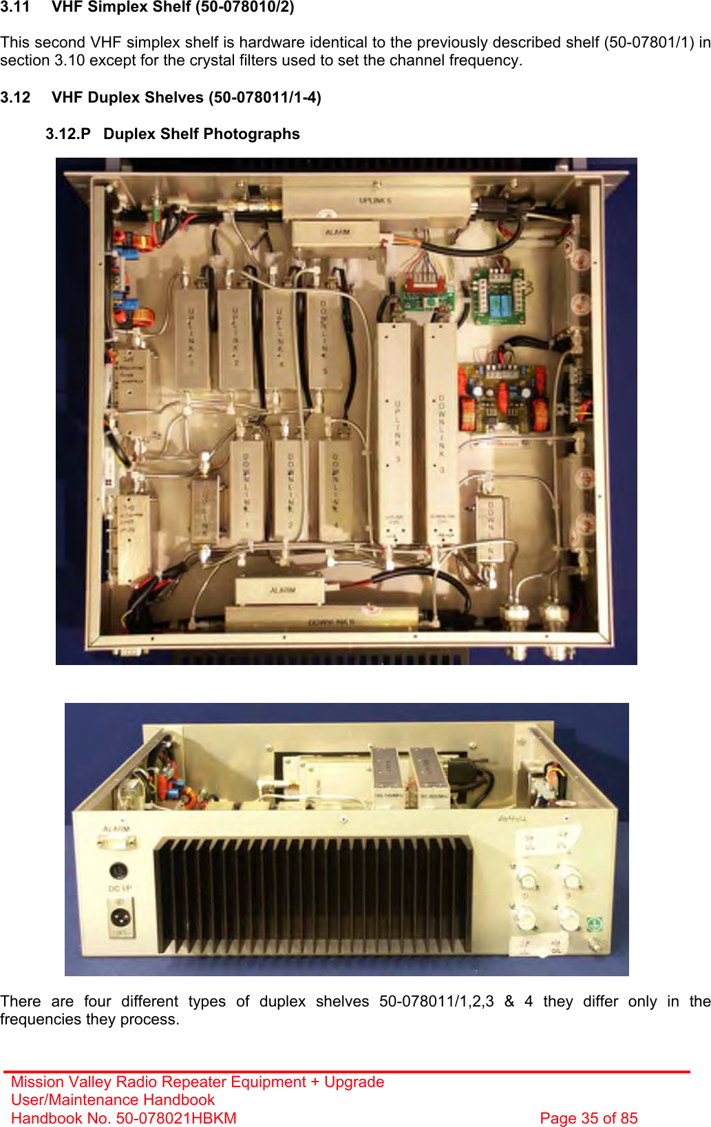
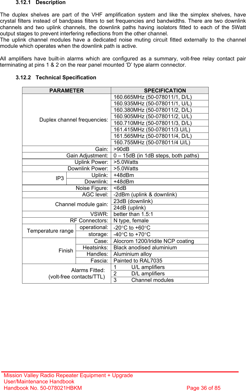
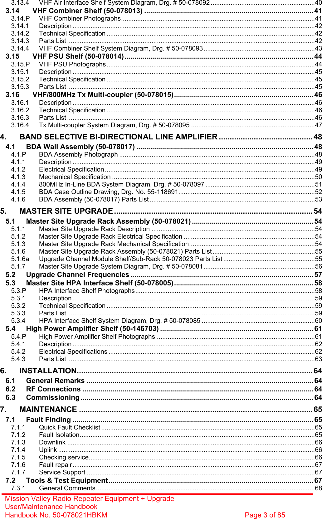
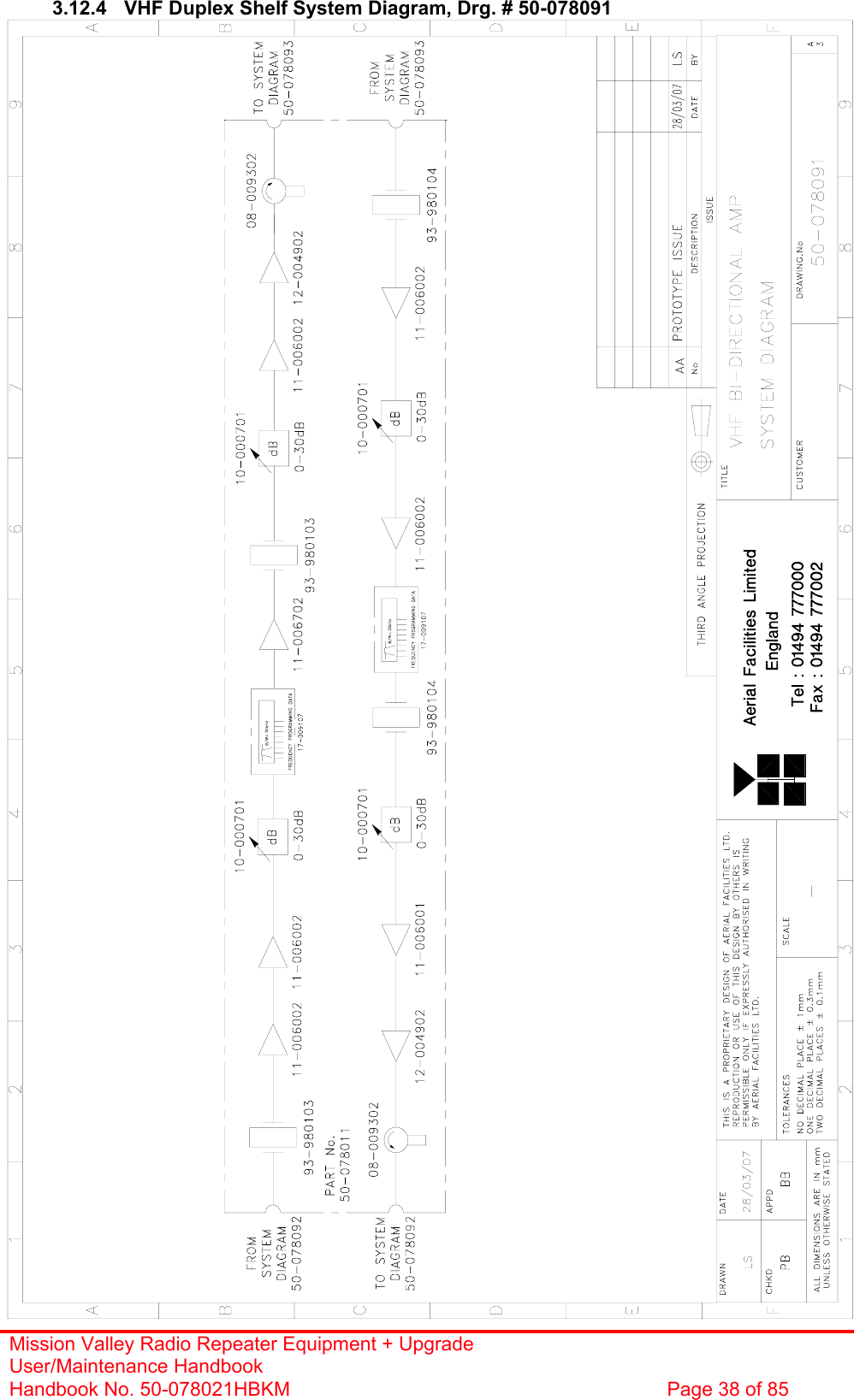
![Mission Valley Radio Repeater Equipment + Upgrade User/Maintenance Handbook Handbook No. 50-078021HBKM Page 37 of 85 3.12.3 Parts List AFL Part # Part Description Qty. 08-930002 2 PORT ISOLATOR 150-300MHz SMA 2 10-000901 SW. ATTENUATOR 0.25W 0-15dB 4 11-006002 LNA VHF 70-500MHz WITH RELAY 7 12-002201 3 STAGE AMPLIFIER ALARM BOARD 1 12-002203 3 STAGE ALARM BOARD SIMPLEX 1 12-002220 3 STAGE ALARM PCB COVER 2 12-004902 POWER AMP VHF 5W CLASS AB 2 13-001803 DUAL DC/DC CONVERTER 24V-12V 1A 2 13-001822 DC-DC CON 24V-5V/15V COVER 1 13-002812 SWITCH VERSION OF SIMPLEX CONT. 1 17-001105 CE AGC UNIT LOG DET/AMP ASSY (24V) 1 17-009135 VHF 15K step CH MOD 15kHz 8p BW+IFRX 2 19-000826 2U,3U,4U 19" UNIT 400 DEEP LID 1 19-000921 3U 19" UNIT 400 DEEP CHASSIS + BKT 1 19-000924 3U 19" UNIT FRONT PANEL FAB 1 80-063920 HEATSINK 2U ASS140 (5W) MILCHBUCK 2 91-030002 N ADAPTOR PANEL FEMALE:FEMALE 4 91-500001 POWER PLG 3 PIN PNL.MOUNT NC-X 1 91-510003 3 PIN R.ANGLE FREE SOC.NC-X. 1 91-600001 'D'TYPE 9 WAY PLUG S/B TERM 1 91-600014 'D' 9 WAY SOCKET S/B (NON FILTERED) 7 91-620001 'D' 25 WAY SOCKET S/B TERM 2 91-700017 ICD 15 WAY 0.1' CONNECTOR 2 96-110001 FUSE HOLDER 20 x 5mm 6.3A 1 96-700034 LED RED 5mm IP67 INTEGRAL RES. 24V 1 96-700035 LED GREEN 5mm IP67 INTEGRAL RES 24V 1 97-400005 HANDLE TYPE H6802 3U [ALLOY] 2 *93-980103 160.665MHz CRYSTAL FILT FAN4M52500 2 *93-980104 160.935MHz CRYSTAL FILT FAN4M52500 2 *93-980105 160.380MHz CRYSTAL FILT FAN4M52500 2 *93-980106 160.905MHz CRYSTAL FILT FAN4M52500 2 *93-980107 160.710MHz CRYSTAL FILT FAN4M52500 2 *93-980108 161.415MHz CRYSTAL FILT FAN4M52500 2 *93-980110 161.565MHz CRYSTAL FILT FAN4M52500 2 *93-980111 160.755MHz CRYSTAL FILT FAN4M52500 2 * These frequency selection crystals are different for each VHF duplex Cell Enhancer shelf.](https://usermanual.wiki/PBE-Europe-as-Axell-Wireless/50-0780-800.Manual/User-Guide-777495-Page-37.png)
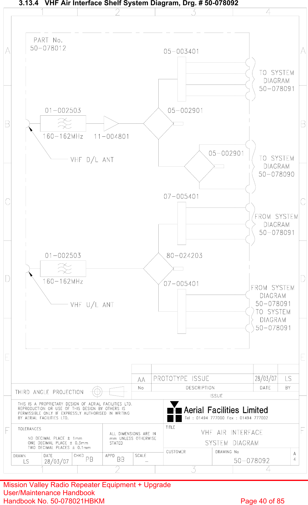
![Mission Valley Radio Repeater Equipment + Upgrade User/Maintenance Handbook Handbook No. 50-078021HBKM Page 39 of 85 3.13 VHF Air Interface Shelf (50-078012) 3.13.1 Description The VHF system is provided with three Yagi off-air antennas, two downlink, receiving downlink signals from two different directions, and one uplink, facing the nearest BTS. Bandpass filters exclude extraneous noise on the frequency bands to be processed and once filtered, the downlink signal is amplified (10dB gain) and separately split to the simplex and duplex shelves’ inputs. The uplink outputs from these six VHF shelves are combined, filtered and sent directly to the uplink off-air Yagi antenna. The downlink low-noise-amplifier has an alarm, configured as a summary, volt-free relay contact pair terminating at pins 1 & 2 on the ‘D’ type alarm connector. 3.13.2 Technical Specification PARAMETER SPECIFICATION Frequency range: 160-162MHz (D/L, U/L) VSWR: better than 1.5:1 Shelf size: 3U Insertion loss: <1.5dB Rejection: >30dB RF connectors: N type, female operational: -20°C to +60°C Temperature range storage: -40°C to +70°C Case: Alocrom 1200/Iridite NCP Heatsinks: None Handles: Aluminium alloy Finish Fascia: Painted to RAL 7035 Alarms Fitted: ‘D’ connector, pins 1& 2 3.13.3 Parts List AFL Part # Part Description Qty. 01-002503 FILTER VHF H/B 6 SMA S 100W 2 05-002901 3dB BROADBAND SPLITTER SMA 1WATT 2 05-003401 4 WAY SPLITTER LOW POWER 1 07-005401 160-470MHz 3 WAY SPLITTER 2 11-004802 450MHz (10dB GAIN) LNA 12V. 1 12-002801 SINGLE CHANNEL ALARM BOARD STD 1 13-001803 DUAL DC/DC CONVERTER 24V-12V 1A 1 19-000826 2U,3U,4U 19" UNIT 400 DEEP LID 1 19-000921 3U 19" UNIT 400 DEEP CHASSIS + BKT 1 80-024203 TRANSMITTER HYBD COUPL.3 PORT 1 80-063627 3U FRONT PANEL FOR H/S 80-063920 1 91-030002 N ADAPTOR PANEL FEMALE:FEMALE 15 91-500001 POWER PLG 3 PIN PNL.MOUNT NC-X 1 91-510003 3 PIN R.ANGLE FREE SOC.NC-X. 1 91-700017 ICD 15 WAY 0.1' CONNECTOR 6 93-540035 1K3 0.25W 1% RES MRS25 M:F 2 96-110001 FUSE HOLDER 20 x 5mm6.3A 1 96-700034 LED RED 5mm IP67 INTEGRAL RES. 24V 1 96-700035 LED GREEN 5mm IP67 INTEGRAL RES 24V 1 97-400005 HANDLE TYPE H6802 3U [ALLOY] 2](https://usermanual.wiki/PBE-Europe-as-Axell-Wireless/50-0780-800.Manual/User-Guide-777495-Page-39.png)
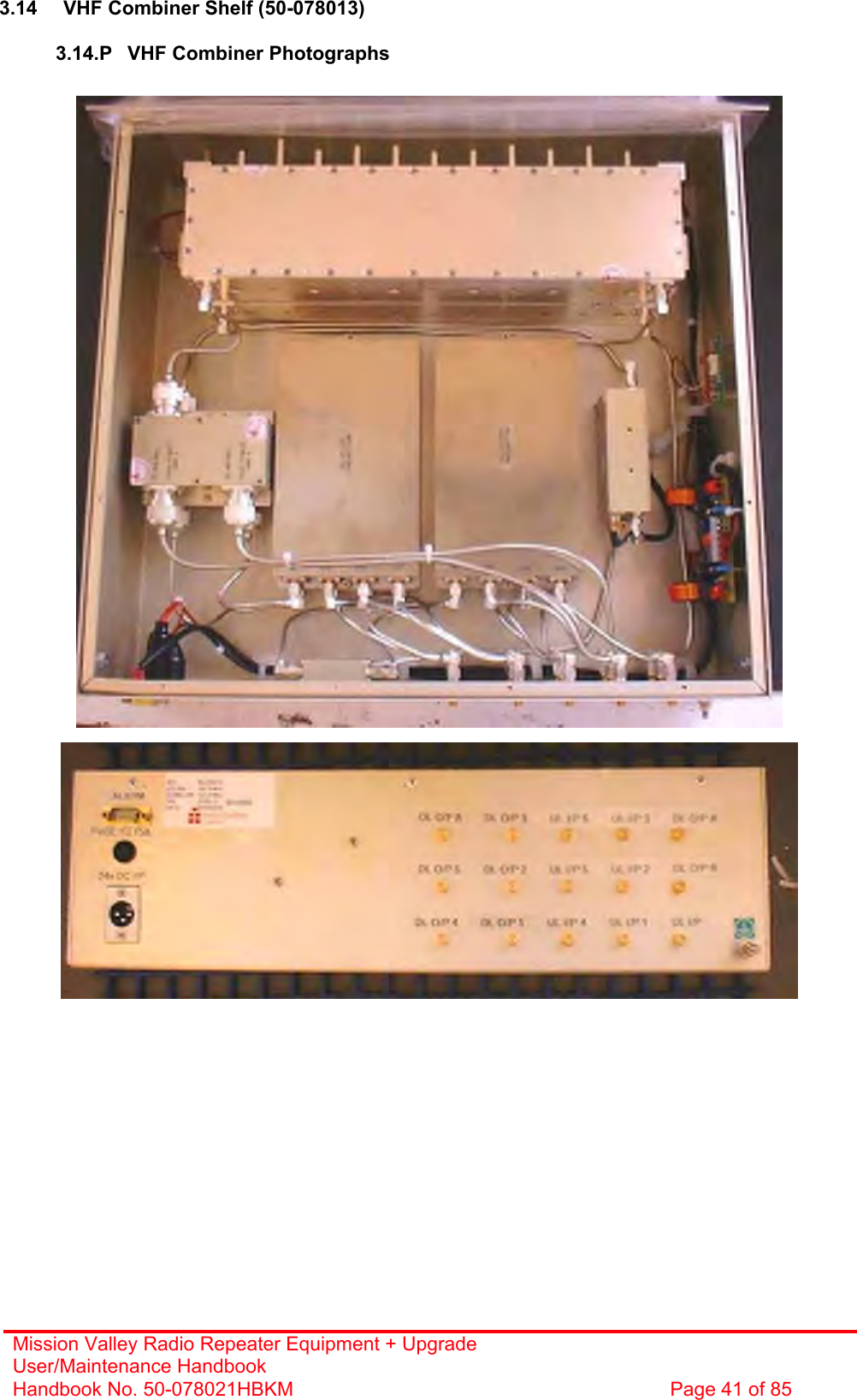
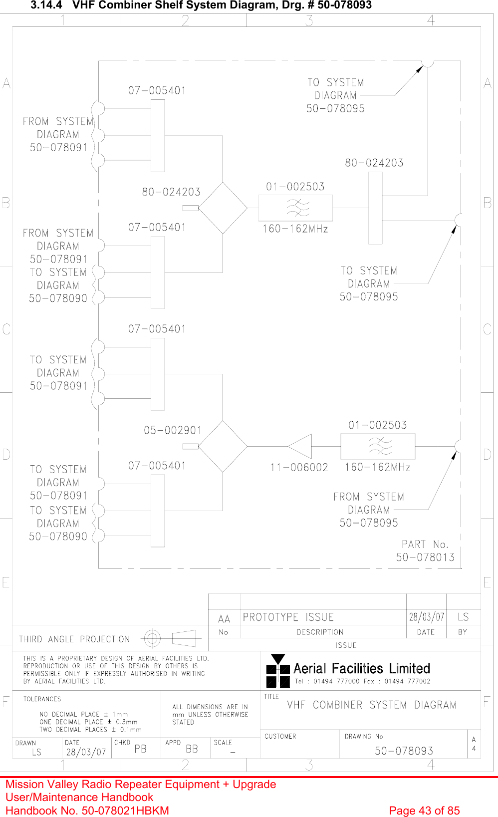
![Mission Valley Radio Repeater Equipment + Upgrade User/Maintenance Handbook Handbook No. 50-078021HBKM Page 42 of 85 3.14.1 Description The purpose of the VHF combiner is to take the downlink products of all the VHF shelves and combine them together so that they may, in turn, be combined with the 800MHz signals from the cellular amplifiers to feed the tunnel antennas. The reverse is true of the uplink path where the VHF signals from each of the tunnel antennæ are coupled from the 800MHz signals, filtered, amplified, combined and then split equally for the inputs of the VHF uplink amplifiers. The uplink low-noise-amplifier used in the shelf, has an alarm pair, configured as a summary, volt-free relay contact pair terminating at pins 1 & 2 on the ‘D’ type alarm connector. 3.14.2 Technical Specification PARAMETER SPECIFICATION Frequency ranges: 160-162MHz (D/L, U/L) VSWR: better than 1.5:1 Shelf size: 3U Uplink amplifier gain: 20dB (typical) Rejection: >30dB RF connectors: N type, female operational: -20°C to +60°C Temperature range storage: -40°C to +70°C Case: Alocrom 1200/Iridite NCP Heatsinks: None Handles: Aluminium alloy Finish Fascia: Painted to RAL 7035 Alarms Fitted: ‘D’ connector, pins 1& 2 3.14.3 Parts List AFL Part # Part Description Qty. 01-002503 FILTER VHF H/B 6 SMA S 100W 2 05-002901 3dB BROADBAND SPLITTER SMA 1WATT 1 07-005401 160-470MHz 3 WAY SPLITTER 4 11-006002 LNA VHF 70-500MHz WITH RELAY 1 13-001803 DUAL DC/DC CONVERTER 24V-12V 1A 1 19-000826 2U,3U,4U 19" UNIT 400 DEEP LID 1 19-000921 3U 19" UNIT 400 DEEP CHASSIS + BKT 1 80-024203 TRANSMITTER HYBD COUPL.3 PORT 2 80-063627 3U FRONT PANEL FOR H/S 80-063920 1 91-030002 N ADAPTOR PANEL FEMALE:FEMALE 15 91-500001 POWER PLG 3 PIN PNL.MOUNT NC-X 1 91-510003 3 PIN R.ANGLE FREE SOC.NC-X. 1 93-540035 1K3 0.25W 1% RES MRS25 M:F 2 96-110001 FUSE HOLDER 20 x 5mm6.3A 1 96-700034 LED RED 5mm IP67 INTEGRAL RES. 24V 1 96-700035 LED GREEN 5mm IP67 INTEGRAL RES 24V 1 97-400005 HANDLE TYPE H6802 3U [ALLOY] 2](https://usermanual.wiki/PBE-Europe-as-Axell-Wireless/50-0780-800.Manual/User-Guide-777495-Page-42.png)
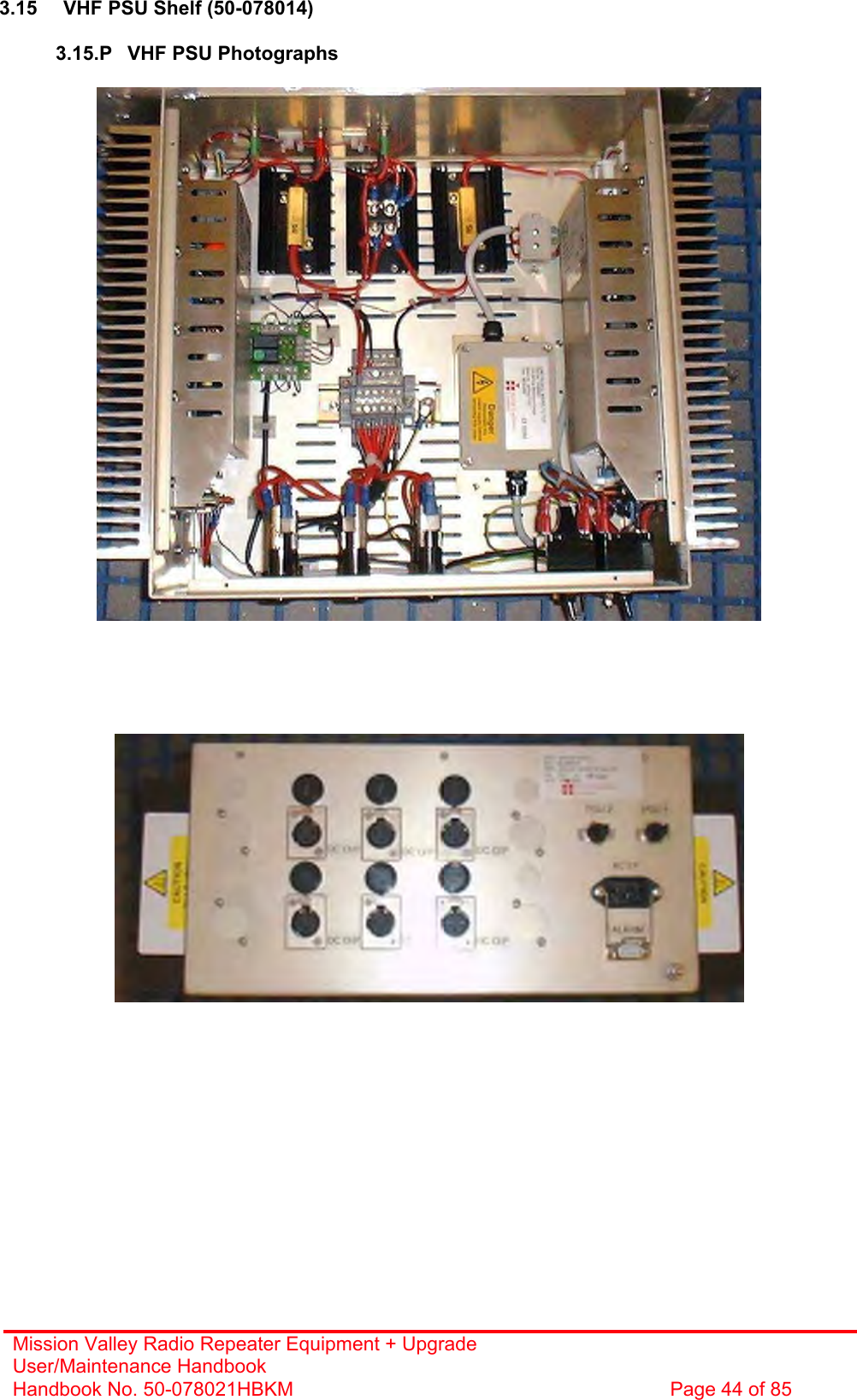
![Mission Valley Radio Repeater Equipment + Upgrade User/Maintenance Handbook Handbook No. 50-078021HBKM Page 45 of 85 3.15.1 Description The power supply shelves are separate for the VHF/UHF and 800MHz cell enhancers. The VHF/UHF supply shelf is a 24V DC shelf which supplies six, 24Volt XLR type connector outputs at a maximum total output power of 800Watts DC. These DC outputs are fused at a 10Amp rating although four of the six DC outputs will be drawing less than 5Amps each at any one time. 3.15.2 Technical Specification PARAMETER SPECIFICATION Input: 110V AC @50/60Hz (single port) Outputs: 6 x 24V DC @ 10A each (fused) Front panel indicators: (x 2) Green LED for ‘PSU1/PSU2 ON’’ Fuses: 1 x 10A each outlet socket DC Socket: XLR operational: -20°C to +60°C Temperature range storage: -40ºC to +70ºC Case: Alocrom 1200/Iridite NCP coating Heatsinks: Black anodised aluminium Handles: Aluminium alloy Finish Fascia: Painted to RAL7035 Alarmed devices: Either PSU failure Alarm interface (volt-free contacts): ‘D’ type alarm connector, pins 1 & 2 MTBF: >50,000 hours Earthing: M8 stud 3.15.3 Parts List AFL Part # Part Description Qty.13-003301 MAINS FILTER 8AMP ASSEMBLY 1 20-001602 24V RELAY BOARD 1 80-008920 DUAL PSU HEATSINK 2 80-008921 DUAL PSU CASE 1 80-008922 DUAL PSU LID 1 80-008925 DUAL PSU FRONT PANEL 1 80-020632 2U CHASSIS LID FIXING RAIL 4 91-500025 3 PIN RIGHT ANGLE FREE PLUG NC-X 6 91-510004 3 PIN PNL.MOUNT SOCKET NC-X 6 91-510035 3 WAY MATE N LOK PLUG HOUSING 2 91-520001 PWR MAINS INL FIXED/SOLD.TERMS 1 91-520005 MAINS LEAD 1 91-520010 MAINS RETAINING CLIP 1 91-520032 MATE N LOK SOCKET CONTACT 20/14 AWG 6 91-600015 'D' 9 WAY PLUG S/B (NON FILTERED) 1 91-800014 3 WAY TERMINAL BLOCK 1 94-100004 STPS12045TV 60A DUAL DIODE 1 96-100001 20 x 5mm,10A FUSE HOLDER/CARRIER 6 96-300054 24V 17A PSU 400W (XP BCC) 2 96-600001 INSULATING BOOT LARGE 1 96-700035 LED GREEN 5mm IP67 INTEGRAL RES 24V 2 96-900017 AC TRIP SWITCH (3 AMP M.C.B.) 2 97-400002 HANDLE TYPE H6803 4U.[ALLOY] 2](https://usermanual.wiki/PBE-Europe-as-Axell-Wireless/50-0780-800.Manual/User-Guide-777495-Page-45.png)
![Mission Valley Radio Repeater Equipment + Upgrade User/Maintenance Handbook Handbook No. 50-078021HBKM Page 63 of 85 5.4.3 Parts List AFL Part # Part Description Qty.05-002602 900MHz SPLITTER/COMBINER, 20W 6 05-002622 SPLITTER/COMBINER AUX. MTG PLATE 6 12-023301 PA 851-866MHz 20W LINEARIZED +24V 4 80-008902 24V RELAY PCB ASSEMBLY **NO LED** 2 80-245121 CLASS A LINEARIZED HEATSINK 2 80-245122 100WTETRA LINEARIZED H'SINK MTG BKT 2 80-245123 100WTETRA LINEARIZED SIDE PANEL 2 80-245124 100WTETRA LINEARIZED RACK LID 2 80-245125 100WTETRA LINEARIZED FRONT PANEL 1 80-245126 100WTETRA LINEARIZED DUCT END PLATE 2 80-245128 100WTETRA LINEARIZED DUCT MTG BLOCK 4 80-245129 100WTETRA LINEARIZED LID MTG BKT 4 80-245130 100WTETRA LINEARIZED DUCT TOP COVER 1 80-245131 100WTETRA LINEARIZED DUCT BOT COVER 1 80-245132 CLASS A LINEARIZED AMP CABLE TIDY 2 90-010021 RF CABLE SUPFLEX SMA R/A MALE 100mm 4 90-010024 RF CABLE SUPFLEX SMA R/A MALE 400mm 2 90-010026 RF CABLE SUPFLEX SMA R/A MALE 150mm 6 90-010027 RF CABLE SUPFLEX SMA R/A MALE 250mm 2 91-130005 SMA BULKHEAD ADAPTOR F/F 2 91-500001 POWER PLG 3 PIN PNL.MOUNT NC-X 2 91-600015 'D' 9 WAY PLUG S/B (NON FILTERED) 2 91-600019 'D'15 WAY SHELL (2W7) 4 91-640004 LARGE PIN FOR 91-660001 D SOCKET 8 91-660001 2W5 MIXED D TYPE SOCKET (7 WAY) 4 91-700017 ICD 15 WAY 0.1' CONNECTOR 2 91-700036 MISC 3 WAY PLUG HOUSING 4 91-700037 MISC 4 WAY PLUG HOUSING 2 91-700038 MISC PLG PIN FOR 3WAY HOUSING 14AWG 32 91-700039 MISC 3 WAY SOCKET HOUSING 6 91-700040 MISC 4 WAY SOCKET HOUSING 2 91-700042 MISC SOC.PIN FOR 3WAY HOUSING 14AWG 12 96-100004 32mm 20A (16A max load) FUSE HOLDER 2 96-110005 315mA FUSE GLASS A/SURGE 20X5 4 96-110015 T 15A A/SURGE FUSE 1.25' 2 96-110040 BULGIN IN-LINE FUSEHOLDER 20mm 4 96-400002 80 X 80MM 24V DC FAN SUNON 4 96-400003 PLASTIC FINGER GUARD 80X80mm 4 96-600003 INSULATING BOOT D.C. 2 96-700034 LED RED 5mm IP67 INTEGRAL RES. 24V 2 96-700035 LED GREEN 5mm IP67 INTEGRAL RES 24V 2 97-400002 HANDLE TYPE H6803 4U.[ALLOY] 2 97-600004 19" SUBRACK REAR RAIL 2 97-600005 19" SUBRACK FRONT RAIL 2 97-600008 19" SUBRACK TAPPED STRIP 2 97-600016 19" 4U SUBRACK MOUNTING FLANGE 2](https://usermanual.wiki/PBE-Europe-as-Axell-Wireless/50-0780-800.Manual/User-Guide-777495-Page-63.png)
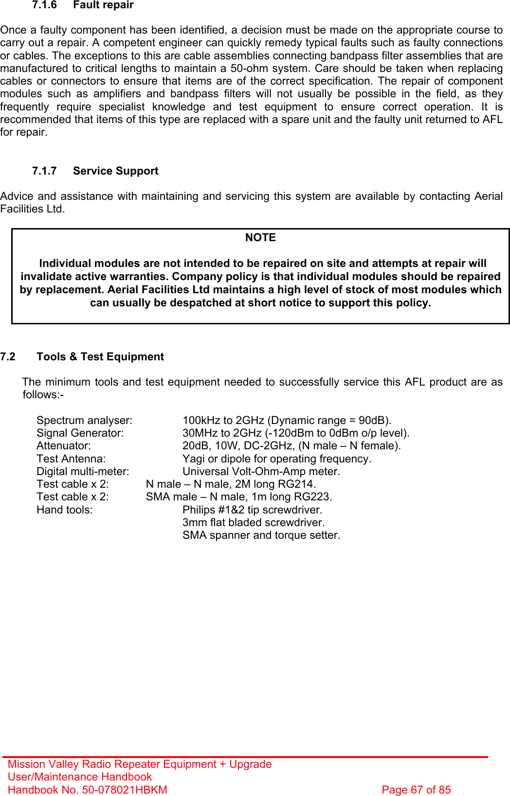
![Mission Valley Radio Repeater Equipment + Upgrade User/Maintenance Handbook Handbook No. 50-078021HBKM Page 72 of 85 A.3 EC Declaration of Conformity In accordance with BS EN ISO/IEC 17050-1&-2:2004 Aerial Facilities Limited Aerial House Asheridge Road Chesham Buckinghamshire HP5 2QD United Kingdom DECLARES, UNDER OUR SOLE RESPONSIBILITY THAT THE FOLLOWING PRODUCT: PRODUCT PART NO[S] 50-078017 & 50-078021 PRODUCT DESCRIPTION Mission Valley Tunnel radio repeater equipment IN ACCORDANCE WITH THE FOLLOWING DIRECTIVES: 1999/5/EC The Radio & Telecommunications Terminal Equipment Directive Annex V and its amending directives HAS BEEN DESIGNED AND MANUFACTURED TO THE FOLLOWING STANDARD[S] OR OTHER NORMATIVE DOCUMENT[S]: BS EN 60950 Information technology equipment. Safety. General requirements ETS EN 301 489-1 EMC standard for radio equipment and services. Part 1. Common technical requirements I hereby declare that the equipment named above has been designed to comply with the relevant sections of the above referenced specifications. The unit complies with all essential requirements of the Directives. SIGNED B S BARTON TECHNICAL DIRECTOR DATE: 22/01/2007 Registered Office: Aerial House, Asheridge Road, Chesham, Buckinghamshire, HP5 2QD England Registered No. 4042808 (England) www.aerialfacilities.com](https://usermanual.wiki/PBE-Europe-as-Axell-Wireless/50-0780-800.Manual/User-Guide-777495-Page-72.png)