PBE Europe as Axell Wireless 50-0780-800 800MHz Cell Enhancer 50-078021 MV Upgrade User Manual Manual
Axell Wireless 800MHz Cell Enhancer 50-078021 MV Upgrade Manual
Contents
- 1. User manual
- 2. Manual
Manual

Aerial Facilities Limited
Technical Literature
Mission Valley Radio Repeater Equipment + Upgrade
User/Maintenance Handbook
Handbook No. 50-078201HBKM Issue No. 2A Date 16/02/2007 Page 1 of 85
Mission Valley Radio System + Upgrade
User/Maintenance Handbook
For
San Diego Association
AFL Works Order # Q111353 & Q11740
AFL product part # 50-078001 (800MHz & VHF CEs)
80-209302 (Battery Backup)
50-078021 (Upgrade hardware)

Mission Valley Radio Repeater Equipment + Upgrade
User/Maintenance Handbook
Handbook No. 50-078021HBKM Page 2 of 85
Table of Contents
1. INTRODUCTION ............................................................................................................5
1.1 Scope and Purpose of document.......................................................................................... 5
1.2 Limitation of Liability Notice.................................................................................................. 5
2. SAFETY CONSIDERATIONS ........................................................................................6
2.1 Earthing of Equipment ........................................................................................................... 6
2.2 Electric Shock Hazard ............................................................................................................ 6
2.3 RF Radiation Hazard............................................................................................................... 6
2.4 Lifting and other Health and Safety Recommendations ..................................................... 6
2.5 Chemical Hazard ..................................................................................................................... 7
2.6 Laser safety............................................................................................................................. 7
2.7 Emergency Contact Numbers................................................................................................ 7
3. MASTER SITE RACKS (50-078001)..............................................................................8
3.1 Master Site Description .......................................................................................................... 8
3.P Master Site Rack Photos ........................................................................................................8
3.2 Master Site Electrical Specification .................................................................................... 13
3.3 Master Site Mechanical Specifications ............................................................................... 13
3.4 Master Site Parts List (50-078001)....................................................................................... 14
3.5 Channel Frequency Listing.................................................................................................. 15
3.6 Master Site Drawings............................................................................................................16
3.6.1 Master Site Racks Layout Drawing, Drg. # 50-078051 ...................................................................16
3.7 800MHz Air I/F + BSCE Uplink Shelf (50-078002) ............................................................... 18
3.7.P 800MHz AIF Shelf Photographs ......................................................................................................18
3.7.1 Description .......................................................................................................................................19
3.7.2 Technical Specification ....................................................................................................................19
3.7.3 Parts List ..........................................................................................................................................20
3.7.4 800MHz Off-Air Repeater System Diagram, Drg. # 50-078082 ......................................................21
3.8 800MHz 8Ch. Channel Module Sub-Rack (50-078003)....................................................... 22
3.8.P 800MHz Channel Module Sub-Rack Photographs..........................................................................22
3.8.1 Description .......................................................................................................................................22
3.8.2 Technical Specification ....................................................................................................................22
3.8.3 VHF/ UHF Programming Procedure ................................................................................................23
3.8.4 VHF/ UHF Programming Example...................................................................................................24
3.8.5 900MHz Programming Procedure ...................................................................................................25
3.8.6 Parts List ..........................................................................................................................................26
3.8.7 8 Channel Module Shelf System Diagram, Drg. # 50-078083 ........................................................27
3.9 800MHz 40Watt Power Amplifier/Driver Shelf (50-078004)................................................ 28
3.9.P 40Watt PA Shelf Photographs .........................................................................................................28
3.9.1 Description .......................................................................................................................................29
3.9.2 Technical Specification ....................................................................................................................29
3.9.3 Parts List ..........................................................................................................................................30
3.10 VHF Simplex Shelf (50-078010/1) .....................................................................................31
3.10.P VHF Simplex Shelf Photographs .....................................................................................................31
3.10.1 Description .......................................................................................................................................32
3.10.2 Technical Specification ....................................................................................................................32
3.10.3 Parts List ..........................................................................................................................................33
3.10.4 VHF Shelf System Diagram, Drg. # 50-078090...............................................................................34
3.11 VHF Simplex Shelf (50-078010/2) .....................................................................................35
3.12 VHF Duplex Shelves (50-078011/1-4) ............................................................................... 35
3.12.P Duplex Shelf Photographs ...............................................................................................................35
3.12.1 Description .......................................................................................................................................36
3.12.2 Technical Specification ....................................................................................................................36
3.12.3 Parts List ..........................................................................................................................................37
3.12.4 VHF Duplex Shelf System Diagram, Drg. # 50-078091 ..................................................................38
3.13 VHF Air Interface Shelf (50-078012) ................................................................................. 39
3.13.1 Description .......................................................................................................................................39
3.13.2 Technical Specification ....................................................................................................................39
3.13.3 Parts List ..........................................................................................................................................39

Mission Valley Radio Repeater Equipment + Upgrade
User/Maintenance Handbook
Handbook No. 50-078021HBKM Page 3 of 85
3.13.4 VHF Air Interface Shelf System Diagram, Drg. # 50-078092 ..........................................................40
3.14 VHF Combiner Shelf (50-078013) .....................................................................................41
3.14.P VHF Combiner Photographs............................................................................................................41
3.14.1 Description .......................................................................................................................................42
3.14.2 Technical Specification ....................................................................................................................42
3.14.3 Parts List ..........................................................................................................................................42
3.14.4 VHF Combiner Shelf System Diagram, Drg. # 50-078093..............................................................43
3.15 VHF PSU Shelf (50-078014)...............................................................................................44
3.15.P VHF PSU Photographs....................................................................................................................44
3.15.1 Description .......................................................................................................................................45
3.15.2 Technical Specification ....................................................................................................................45
3.15.3 Parts List ..........................................................................................................................................45
3.16 VHF/800MHz Tx Multi-coupler (50-078015)...................................................................... 46
3.16.1 Description .......................................................................................................................................46
3.16.2 Technical Specification ....................................................................................................................46
3.16.3 Parts List ..........................................................................................................................................46
3.16.4 Tx Multi-coupler System Diagram, Drg. # 50-078095 .....................................................................47
4. BAND SELECTIVE BI-DIRECTIONAL LINE AMPLIFIER ........................................... 48
4.1 BDA Wall Assembly (50-078017) ......................................................................................... 48
4.1.P BDA Assembly Photograph .............................................................................................................48
4.1.1 Description .......................................................................................................................................49
4.1.2 Electrical Specification .....................................................................................................................49
4.1.3 Mechanical Specification .................................................................................................................50
4.1.4 800MHz In-Line BDA System Diagram, Drg. # 50-078097 .............................................................51
4.1.5 BDA Case Outline Drawing, Drg. N. 55-118691............................................................................52
4.1.6 BDA Assembly (50-078017) Parts List ............................................................................................53
5. MASTER SITE UPGRADE........................................................................................... 54
5.1 Master Site Upgrade Rack Assembly (50-078021) ............................................................. 54
5.1.1 Master Site Upgrade Rack Description ...........................................................................................54
5.1.2 Master Site Upgrade Rack Electrical Specification .........................................................................54
5.1.3 Master Site Upgrade Rack Mechanical Specification......................................................................54
5.1.6 Master Site Upgrade Rack Assembly (50-078021) Parts List .........................................................55
5.1.6a Upgrade Channel Module Shelf/Sub-Rack 50-078023 Parts List ...................................................55
5.1.7 Master Site Upgrade System Diagram, Drg. # 50-078081..............................................................56
5.2 Upgrade Channel Frequencies ............................................................................................57
5.3 Master Site HPA Interface Shelf (50-078005)...................................................................... 58
5.3.P HPA Interface Shelf Photographs....................................................................................................58
5.3.1 Description .......................................................................................................................................59
5.3.2 Technical Specification ....................................................................................................................59
5.3.3 Parts List ..........................................................................................................................................59
5.3.4 HPA Interface Shelf System Diagram, Drg. # 50-078085 ...............................................................60
5.4 High Power Amplifier Shelf (50-146703) ............................................................................. 61
5.4.P High Power Amplifier Shelf Photographs ........................................................................................61
5.4.1 Description .......................................................................................................................................62
5.4.2 Electrical Specifications ...................................................................................................................62
5.4.3 Parts List ..........................................................................................................................................63
6. INSTALLATION............................................................................................................64
6.1 General Remarks .................................................................................................................. 64
6.2 RF Connections .................................................................................................................... 64
6.3 Commissioning ..................................................................................................................... 64
7. MAINTENANCE ...........................................................................................................65
7.1 Fault Finding ......................................................................................................................... 65
7.1.1 Quick Fault Checklist .......................................................................................................................65
7.1.2 Fault Isolation...................................................................................................................................65
7.1.3 Downlink ..........................................................................................................................................66
7.1.4 Uplink ...............................................................................................................................................66
7.1.5 Checking service..............................................................................................................................66
7.1.6 Fault repair.......................................................................................................................................67
7.1.7 Service Support ...............................................................................................................................67
7.2 Tools & Test Equipment....................................................................................................... 67
7.3.1 General Comments..........................................................................................................................68

Mission Valley Radio Repeater Equipment + Upgrade
User/Maintenance Handbook
Handbook No. 50-078021HBKM Page 4 of 85
7.3.2 Module Removal (LNAs, general procedure): .................................................................................68
7.3.3 Module Replacement (general): ......................................................................................................68
7.3.4 Power Amplifiers ..............................................................................................................................68
7.3.5 Low Power Amplifier Replacement..................................................................................................69
7.3.6 Module Transportation:....................................................................................................................69
APPENDIX A......................................................................................................................... 70
A.1 Glossary of Terms used in this document............................................................................. 70
A.2 Key to AFL RF Module Drawing Symbols .............................................................................. 71
A.3 EC Declaration of Conformity.................................................................................................. 72
A.4 Amendment List Record Sheet ...............................................................................................73
A.5. Waste Electrical and Electronic Equipment (WEEE) Notice................................................ 74
APPENDIX B INITIAL EQUIPMENT SET-UP CALCULATIONS ....................................... 75
APPENDIX C - BATTERY BACKUP.....................................................................................76
C.1 GENERAL DESCRIPTION........................................................................................76
C.2. BATTERY BACKUP PHOTOGRAPHS.....................................................................77
C.3. SPECIFICATION .......................................................................................................78
C.3.1 Technical Specification..................................................................................................... 78
C.3.2 Mechanical Specification.................................................................................................. 78
C.3.3 Technical Description .......................................................................................................79
C.4. GENERAL DRAWINGS ............................................................................................80
C.4.1 Drg. No. 80-209374, 160Ah 12V Battery Backup Circuit Diagram ................................. 80
C.4.2 Low Voltage Battery Disconnect and O/P Voltage Limiter Schematic ......................... 81
C.4.3 Battery Backup Case Outline Drawing ............................................................................ 82
C.4.4 BBU/Amplifier Power Wiring And Alarms Diagram........................................................ 83
C.5. BBU ALARMS & MONITORING SYSTEM ............................................................... 84
C.5.1 Description......................................................................................................................... 84
C.6. INSTALLATION.........................................................................................................85
C.6.1 Battery Backup Unit Installation ...................................................................................... 85
C.6.2 Power Supply Input Voltage Selection ............................................................................ 85
C.7. MAINTENANCE ........................................................................................................85
C.7.1 General Comments............................................................................................................85

Mission Valley Radio Repeater Equipment + Upgrade
User/Maintenance Handbook
Handbook No. 50-078021HBKM Page 5 of 85
1. INTRODUCTION
1.1 Scope and Purpose of document
This handbook is for use solely with the equipment identified by the AFL Part Number shown on the
front cover. It is not to be used with any other equipment unless specifically authorised by Aerial
Facilities Limited.
The purpose of this handbook is to provide the user/maintainer with sufficient information to service
and repair the equipment to the level agreed. Maintenance and adjustments to any deeper level must
be performed by AFL, normally at the company’s repair facility in Chesham, England.
This handbook has been prepared in accordance with BS 4884, and AFL’s Quality procedures, which
maintain the company’s registration to BS EN ISO 9001:2000 and to the R&TTE Directive of the
European Parliament. Copies of the relevant certificates and the company Quality Manual can be
supplied on application to the Quality Manager.
This document fulfils the relevant requirements of Article 6 of the R&TTE Directive.
1.2 Limitation of Liability Notice
This manual is written for the use of technically competent operators/service persons. No liability is
accepted by AFL for use or misuse of this manual, the information contained herein, or the
consequences of any actions resulting from the use of the said information, including, but not limited
to, descriptive, procedural, typographical, arithmetical, or listing errors.
Furthermore, AFL does not warrant the absolute accuracy of the information contained within this
manual, or its completeness, fitness for purpose, or scope.
AFL has a policy of continuous product development and enhancement, and as such, reserves the
right to amend, alter, update and generally change the contents, appearance and pertinence of this
document without notice.
All AFL products carry a twelve month warranty from date of shipment. The warranty is expressly on a
return to base repair or exchange basis and the warranty cover does not extend to on-site repair or
complete unit exchange.
Mission Valley Radio Repeater Equipment + Upgrade
User/Maintenance Handbook
Handbook No. 50-078021HBKM Page 6 of 85
2. SAFETY CONSIDERATIONS
2.1 Earthing of Equipment
Equipment supplied from the mains must be connected to grounded outlets and earthed
in conformity with appropriate local, national and international electricity supply and
safety regulations.
2.2 Electric Shock Hazard
The risk of electrical shocks due to faulty mains driven power supplies whilst
potentially ever present in any electrical equipment, would be minimised by adherence
to good installation practice and thorough testing at the following stages:
a) Original assembly.
b) Commissioning.
c) Regular intervals, thereafter.
All test equipment must be in good working order prior to its use. High current power supplies can be
dangerous because of the possibility of substantial arcing. Always switch off during disconnection and
reconnection.
2.3 RF Radiation Hazard
RF radiation, (especially at UHF frequencies) arising from transmitter outputs
connected to AFL’s equipment, must be considered a safety hazard.
This condition might only occur in the event of cable disconnection, or because a
‘spare’ output has been left un-terminated. Either of these conditions would impair the
system’s efficiency. No investigation should be carried out until all RF power sources have been
removed. This would always be a wise precaution, despite the severe mismatch between the
impedance of an N type connector at 50, and that of free space at 377, which would severely
mitigate against the efficient radiation of RF power. Radio frequency burns could also be a hazard, if
any RF power carrying components were to be carelessly touched!
Antenna positions should be chosen to comply with requirements (both local & statutory) regarding
exposure of personnel to RF radiation. When connected to an antenna, the unit is capable of
producing RF field strengths, which may exceed guideline safe values especially if used with
antennas having appreciable gain. In this regard the use of directional antennas with backscreens
and a strict site rule that personnel must remain behind the screen while the RF power is on, is
strongly recommended.
Where the equipment is used near power lines or in association with temporary masts not having
lightning protection, the use of a safety earth connected to the case-earthing bolt is strongly advised.
2.4 Lifting and other Health and Safety Recommendations
Certain items of AFL equipment are heavy and care should be taken when lifting them
by hand. Ensure that a suitable number of personnel, appropriate lifting apparatus and
appropriate personal protective equipment is used especially when installing Cell
Enhancers above ground e.g. on a mast or pole.
Mission Valley Radio Repeater Equipment + Upgrade
User/Maintenance Handbook
Handbook No. 50-078021HBKM Page 7 of 85
2.5 Chemical Hazard
Beryllium Oxide, also known as Beryllium Monoxide, or Thermalox™, is sometimes
used in devices within equipment produced by Aerial Facilities Ltd. Beryllium oxide
dust can be toxic if inhaled, leading to chronic respiratory problems. It is harmless if
ingested or by contact.
Products that contain beryllium are load terminations (dummy loads) and some power amplifiers.
These products can be identified by a yellow and black “skull and crossbones” danger symbol (shown
above). They are marked as hazardous in line with international regulations, but pose no threat under
normal circumstances. Only if a component containing beryllium oxide has suffered catastrophic
failure, or exploded, will there be any danger of the formation of dust. Any dust that has been created
will be contained within the equipment module as long as the module remains sealed. For this reason,
any module carrying the yellow and black danger sign should not be opened. If the equipment is
suspected of failure, or is at the end of its life-cycle, it must be returned to Aerial Facilities Ltd for
disposal.
To return such equipment, please contact the Quality Department, who will give you a Returned
Materials Authorisation (RMA) number. Please quote this number on the packing documents, and on
all correspondence relating to the shipment.
PolyTetraFluoroEthylene, (P.T.F.E.) and P.T.F.E. Composite Materials
Many modules/components in AFL equipment contain P.T.F.E. as part of the RF insulation barrier.
This material should never be heated to the point where smoke or fumes are evolved. Any person
feeling drowsy after coming into contact with P.T.F.E. especially dust or fumes should seek medical
attention.
2.6 Laser safety
General good working practices adapted from
EN60825-2: 2004/ EC 60825-2:2004
Do not stare with unprotected eyes or with any unapproved optical device at the fibre ends or
connector faces or point them at other people, Use only approved filtered or attenuating viewing aids.
Any single or multiple fibre end or ends found not to be terminated (for example, matched, spliced)
shall be individually or collectively covered when not being worked on. They shall not be readily
visible and sharp ends shall not be exposed.
When using test cords, the optical power source shall be the last connected and the first
disconnected; use only approved methods for cleaning and preparing optical fibres and optical
connectors.
Always keep optical connectors covered to avoid physical damage and do not allow any dirt/foreign
material ingress on the optical connector bulkheads.
The optical fibre jumper cable maximum bend radius is 3cm; any smaller radii may result in optical
cable breakage or excessive transmission losses.
Caution: The FO units are NOT weather proof.
2.7 Emergency Contact Numbers
The AFL Quality Department can be contacted on:
Telephone +44 (0)1494 777000
Fax. +44 (0)1494 777002
e-mail qa@aerialfacilities.com
Mission Valley Radio Repeater Equipment + Upgrade
User/Maintenance Handbook
Handbook No. 50-078021HBKM Page 8 of 85
3. MASTER SITE RACKS (50-078001)
3.1 Master Site Description
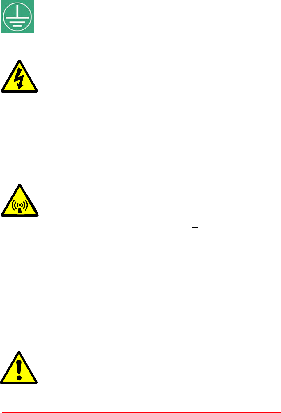
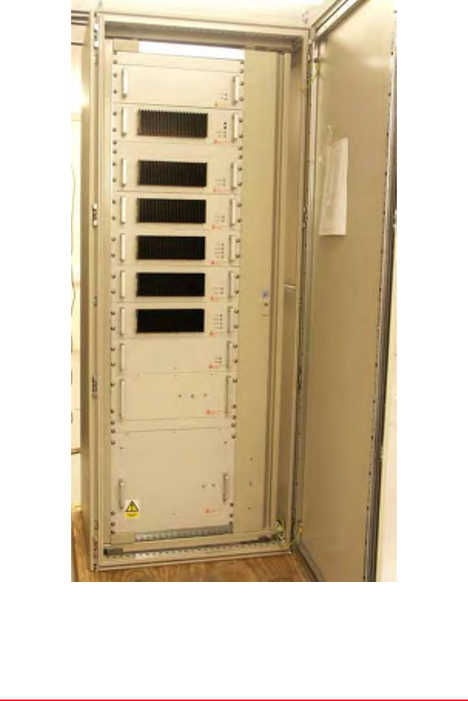
The master site system consists of three, swing-frame 19” rack cabinets which provides 800MHz
Channelised (x 24) & VHF Simplex/Duplex coverage for the various concourses, platforms and
tunnels with a 12V battery backup service (for the 800MHz line amplifiers) that will guarantee
limited continued coverage in case of mains power failure.
3.P Master Site Rack Photos
Mission Valley Radio Repeater Equipment + Upgrade
User/Maintenance Handbook
Handbook No. 50-078021HBKM Page 9 of 85
VHF channel modules and amplifier shelves (front view, door open)
Mission Valley Radio Repeater Equipment + Upgrade
User/Maintenance Handbook
Handbook No. 50-078021HBKM Page 10 of 85
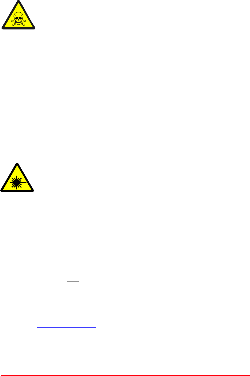
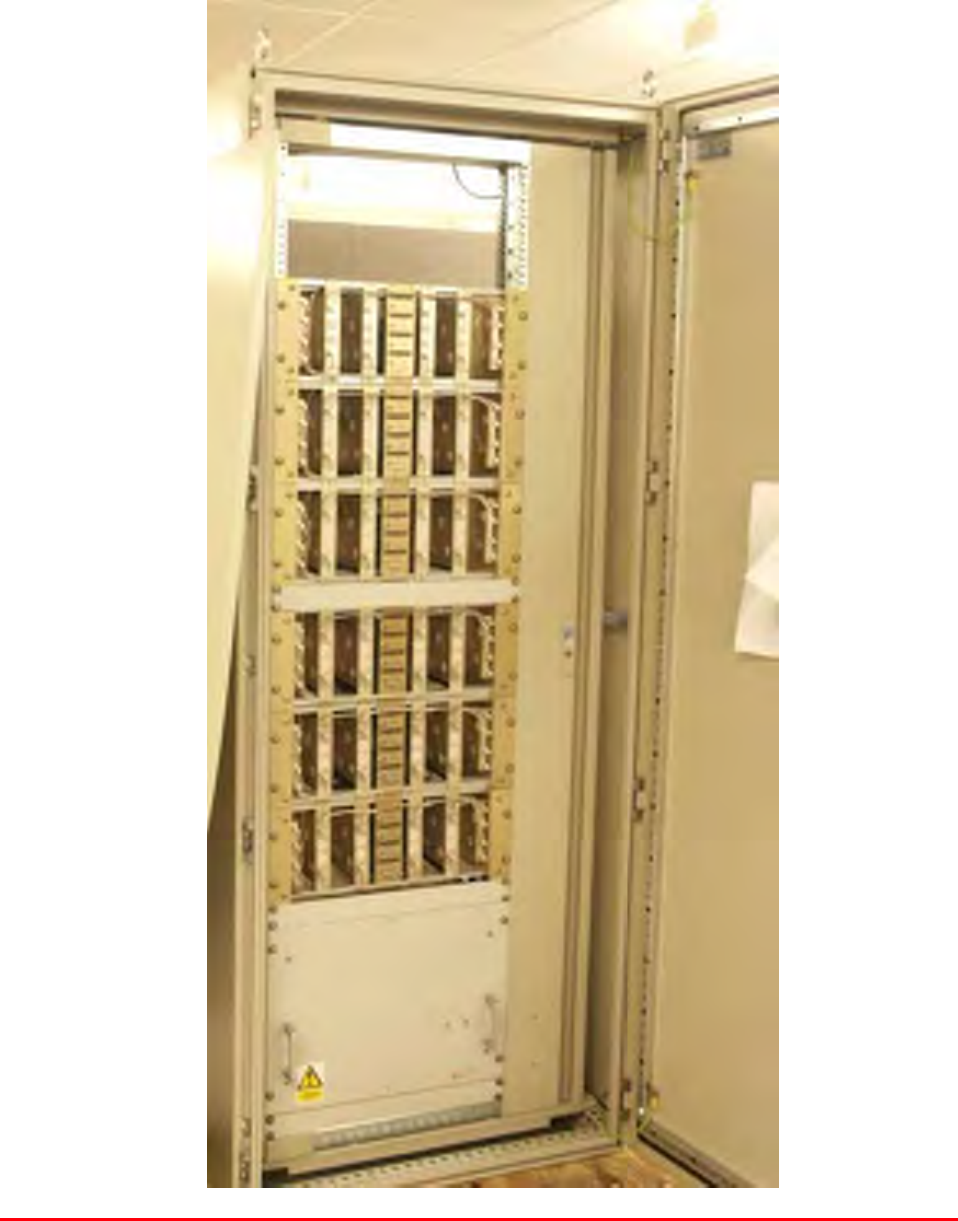
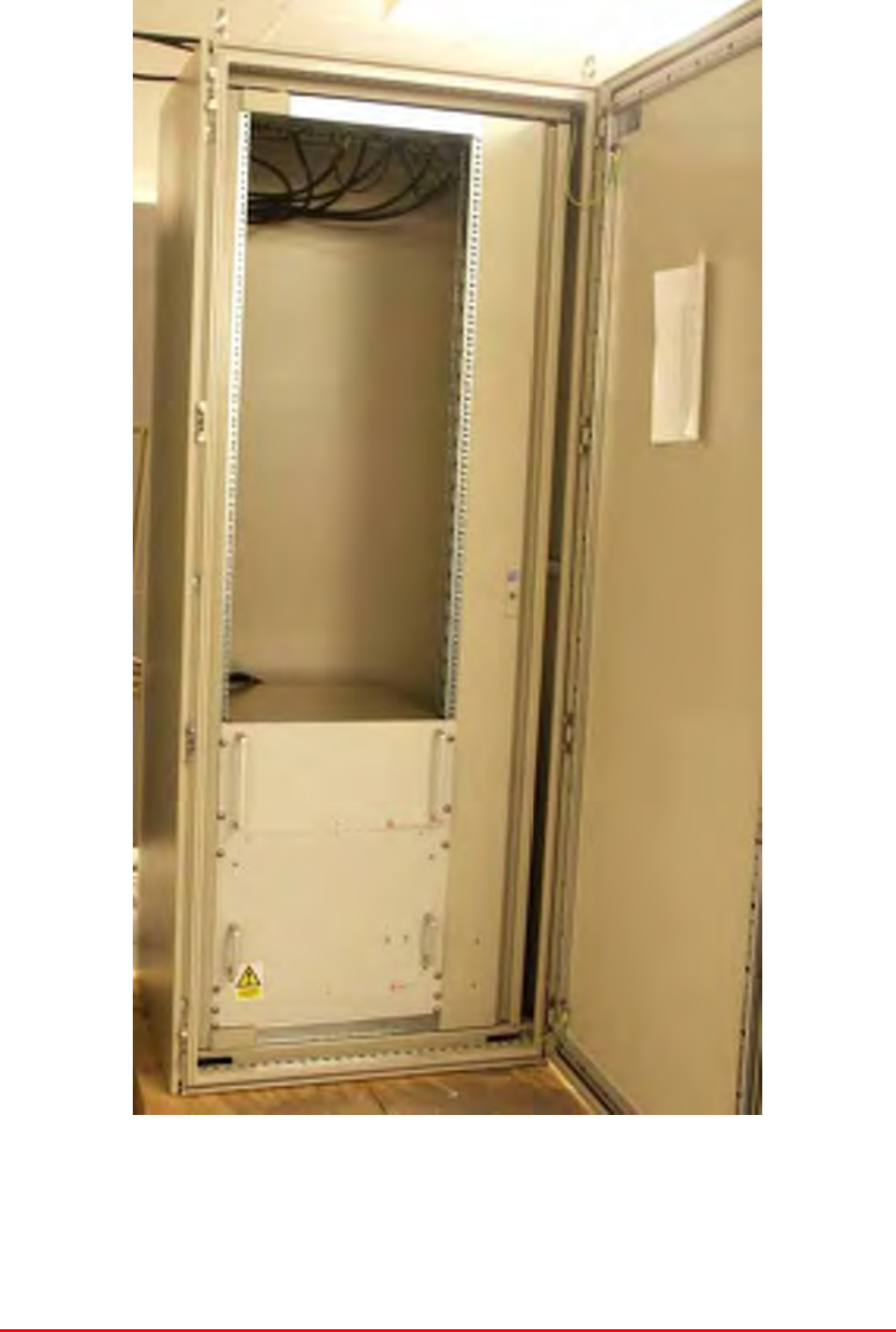
RF distribution rack (front view, door open)
800MHz rack (front view, door open)
Mission Valley Radio Repeater Equipment + Upgrade
User/Maintenance Handbook
Handbook No. 50-078021HBKM Page 11 of 85
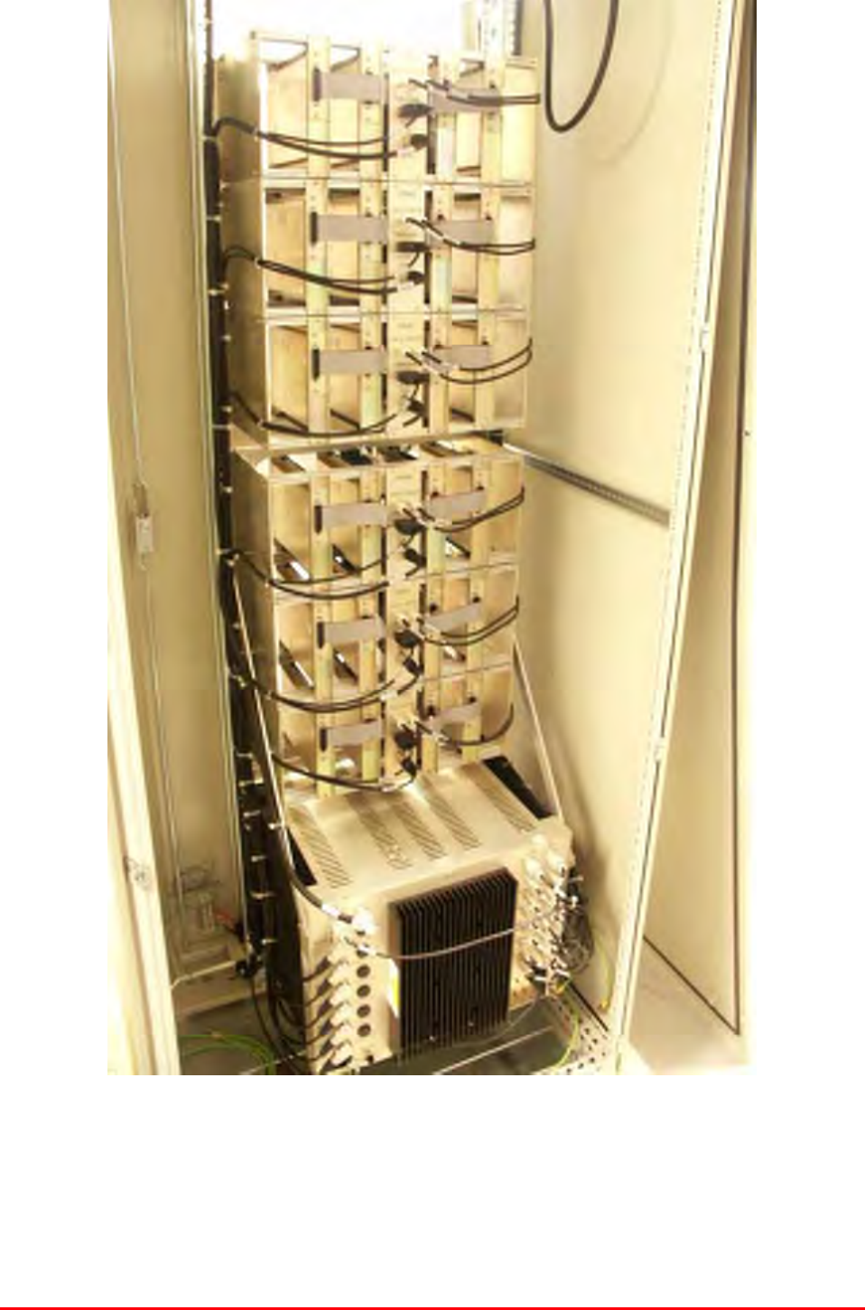
VHF rack (rear view, door open)
Mission Valley Radio Repeater Equipment + Upgrade
User/Maintenance Handbook
Handbook No. 50-078021HBKM Page 12 of 85
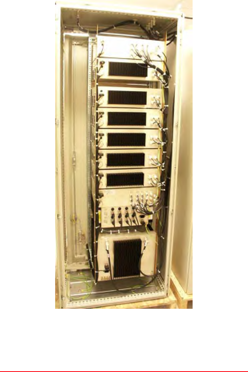
800MHz rack (rear view, door open)
Mission Valley Radio Repeater Equipment + Upgrade
User/Maintenance Handbook
Handbook No. 50-078021HBKM Page 13 of 85
3.2 Master Site Electrical Specification
PARAMETER SPECIFICATION
851-869MHz (Downlink)
Frequency range: 806-824MHz (Uplink)
160.2-161.8MHz (Simplex/Duplex)
18MHz (UHF)
Bandwidth: 1.6MHz (VHF)
>100dB (Uplink)
Gain: >90dB (Downlink)
Gain Adjustment: 0 - 30dB (in 2dB steps)
>5.0Watts (UHF)
Uplink Power: >5.0Watts (VHF)
>40.0Watts (UHF) *(100W upgrade)
Downlink Power >5.0Watts (VHF)
Uplink +43dBm
IP3: Downlink +50dBm (+53dBm upgrade)
Noise Figure: <6dB
AGC: -25dBm (factory set in channel module
)
VSWR: better than 1.5:1
RF Connectors: N type, female
1 PSU’s
2 Amplifiers
Alarms Fitted:
(non-latching, volt-free relay
contacts/TTL) 3 Channel modules
3.3 Master Site Mechanical Specifications
PARAMETER SPECIFICATION
Height: 40U Standard Eurorack (x3)
Width: 19" (482.6mm)
Rack
Depth: 600mm
Height: See parts lists
Width: 19" (482.6mm)
Shelves:
Depth: <450mm(excluding heatsinks, connectors,
and handles)
operational: -20°C to +60°C Temperature
range: storage: -40°C to +70°C
Weight: >100kg
Humidity: 5 – 95% non-condensing
RF Connectors: N type female
Environmental Protection: IP44
Case: Alocrom 1200/Iridite NCP
Heatsinks: Black anodised aluminium
Handles: Aluminium alloy
Finish:
Fascias Painted to RAL7035
Supply Cable:
Unit supplied with suitable supply input
leads, connector and specified length of
cable (where appropriate)

Mission Valley Radio Repeater Equipment + Upgrade
User/Maintenance Handbook
Handbook No. 50-078021HBKM Page 14 of 85
3.4 Master Site Parts List (50-078001)
AFL Part # Part Description Qty.
50-078002 800MHz AIR I/F + BSCE UPLINK SHELF 1
50-078003 800MHz 8CH CHANNEL MOD. SHELF 3
50-078004 800MHz 40W HPA / DRIVER SHELF 2
50-078010/1 VHF SIMPLEX SHELF 1
50-078010/2 VHF SIMPLEX SHELF 1
50-078011/1 VHF DUPLEX SHELF 1
50-078011/2 VHF DUPLEX SHELF 1
50-078011/3 VHF DUPLEX SHELF 1
50-078011/4 VHF DUPLEX SHELF 1
50-078012 VHF AIR I/F SHELF 1
50-078013 VHF COMBINER SHELF 1
50-078014 VHF PSU SHELF 1
50-078015 VHF/ 800 Tx MULTICOUPLER 1
50-078017 800MHz IN LINE AMPLIFIER 2
60-020608 40U SWING FRAME CABINET 3
80-209302 12V 160Ah BATTERY BACK UP STANDARD 2

Mission Valley Radio Repeater Equipment + Upgrade
User/Maintenance Handbook
Handbook No. 50-078021HBKM Page 15 of 85
3.5 Channel Frequency Listing
Frequencies (MHz) Ch. # User
Group Downlink Uplink Status
1 SD Trolley 160.6650 160.9350 Duplex
2 SD Trolley 160.3800 160.9050 Duplex (Note1)
3 SD Trolley 160.7100 161.4150 Duplex
4 SD Trolley 161.2950 161.2950 Simplex
5 SD Trolley 161.5650 160.7550 Duplex
6 SD Trolley 160.5300 160.5300 Simplex
800 MHz Band
1 SD City (PD/FD) 860.0500 815.0500 Duplex
2 SD City (PD/FD) 860.0250 815.0250 Duplex
3 SD City (PD/FD) 859.0500 814.0500 Duplex
4 SD City (PD/FD) 859.0250 814.0250 Duplex
5 SD City (PD/FD) 858.0500 813.0500 Duplex (Note 2)
6 SD City (PD/FD) 858.0250 813.0250 Duplex (Note 2)
7 SD City (PD/FD) 857.0500 812.0500 Duplex
8 SD City (PD/FD) 860.0000 815.0000 Duplex
9 SD City (PD/FD) 859.0000 814.0000 Duplex
10 SD City (PD/FD) 858.0000 813.0000 Duplex (Note 2)
11 SD City (PD/FD) 857.0250 812.0250 Duplex
12 SD City (PD/FD) 857.0000 812.0000 Duplex
13 SD City (PD/FD) 856.0500 811.0500 Duplex
14 SD City (PD/FD) 856.0250 811.0250 Duplex
15 SD City (PD/FD) 862.0500 817.0500 Duplex
16 SD City (PD/FD) 862.1000 817.1000 Duplex
17 SD City (PD/FD) 863.0500 818.0500 Duplex
18 SD City (PD/FD) 864.0500 819.0500 Duplex
19 SD City (PD/FD) 865.5000 820.0500 Duplex
20 SDSU Security 868.5750 823.5750 Duplex (Note 4)
21 SDSU Security 866.3875 821.3875 Duplex (Note 4)
22 SD City (PD/FD) 856.1500 811.1500 Duplex (Note 3)
23 TBD TBD TBD TBD
24 TBD TBD TBD TBD
Note 1: Channel 2 uplink frequency was changed to 160.9050 MHz from 161.9050MHz as required by
the Authority.
Note 2: Channel 4, 5 & 10 uplink frequency changed to 813.0500 MHz, 813.0250MHz, &
813.0000MHz from 816.050 MHz, 816.0250MHz & 816.000MHz respectively.
Note 3: Channel 22 is new frequency pair for SD City with 25KHz channel spacing.
Note 4: Channel 20 & 21 are analogue radio system with digital modulation (3600bps) and the donor
site for these channels has azimuth of 150 degree. The Azimuth of CH 1 to Ch 19 and the
new CH 22 is 40 degree.
Mission Valley Radio Repeater Equipment + Upgrade
User/Maintenance Handbook
Handbook No. 50-078021HBKM Page 16 of 85
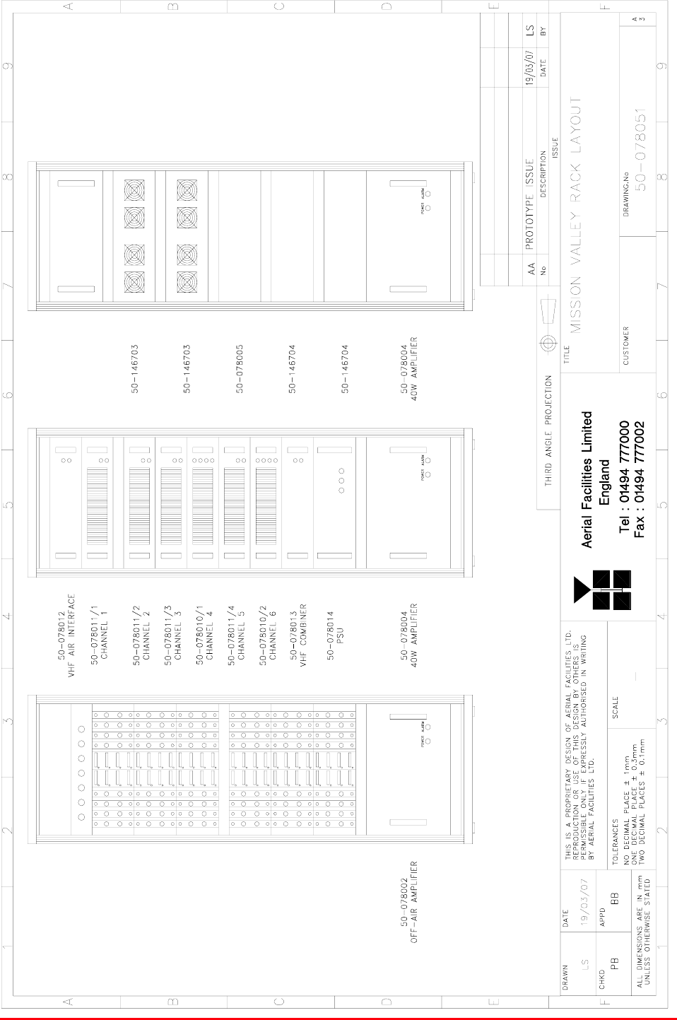
3.6 Master Site Drawings
3.6.1 Master Site Racks Layout Drawing, Drg. # 50-078051
Mission Valley Radio Repeater Equipment + Upgrade
User/Maintenance Handbook
Handbook No. 50-078021HBKM Page 17 of 85
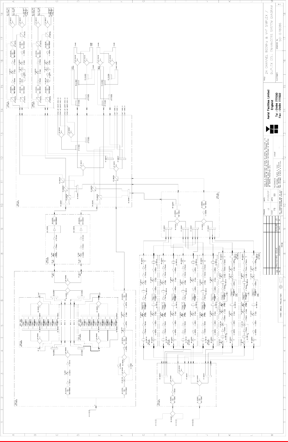
3.6.2 Master Site System Diagram, Drg. # 50-078086
Mission Valley Radio Repeater Equipment + Upgrade
User/Maintenance Handbook
Handbook No. 50-078021HBKM Page 18 of 85
3.7 800MHz Air I/F + BSCE Uplink Shelf (50-078002)
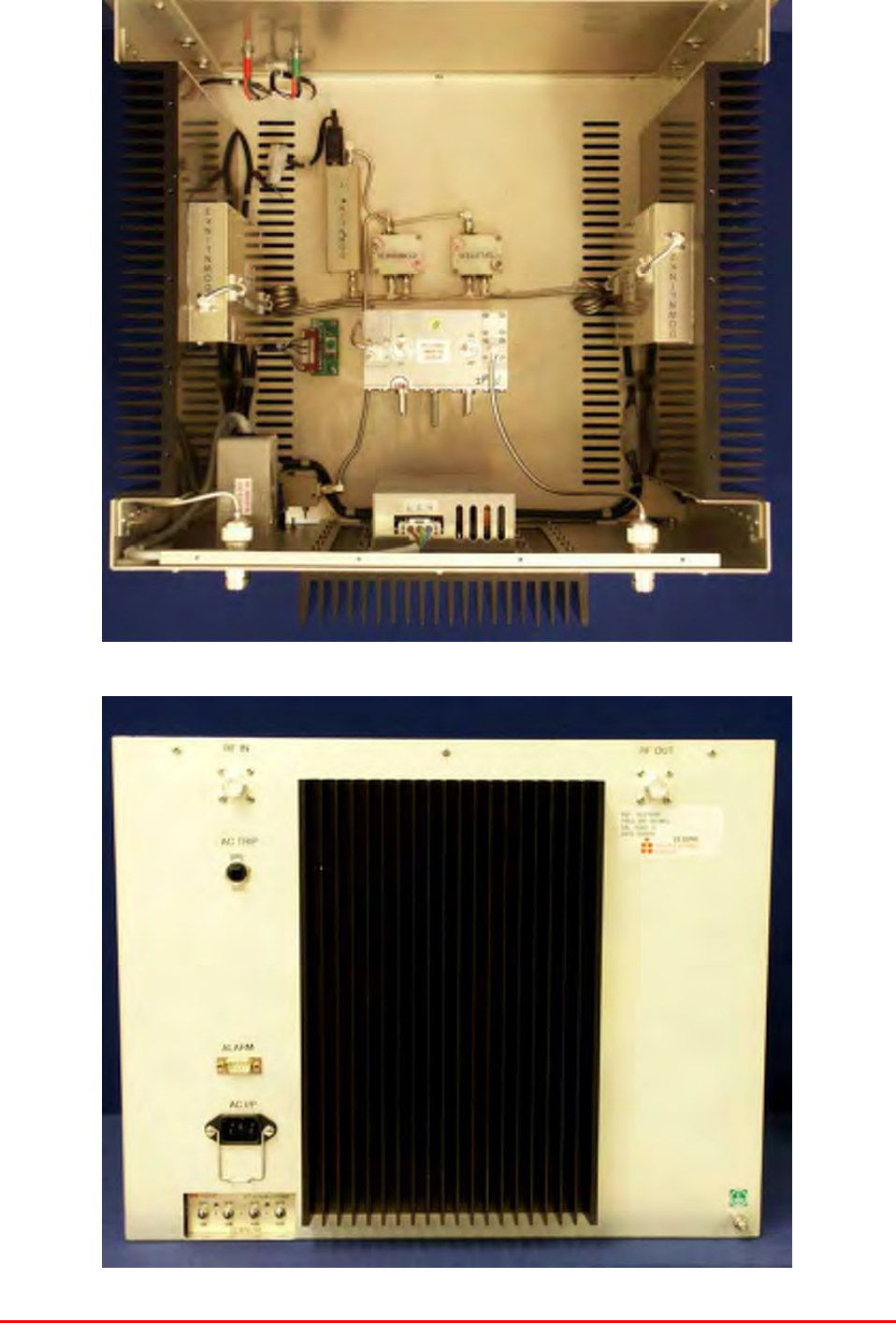
3.7.P 800MHz AIF Shelf Photographs
Mission Valley Radio Repeater Equipment + Upgrade
User/Maintenance Handbook
Handbook No. 50-078021HBKM Page 19 of 85
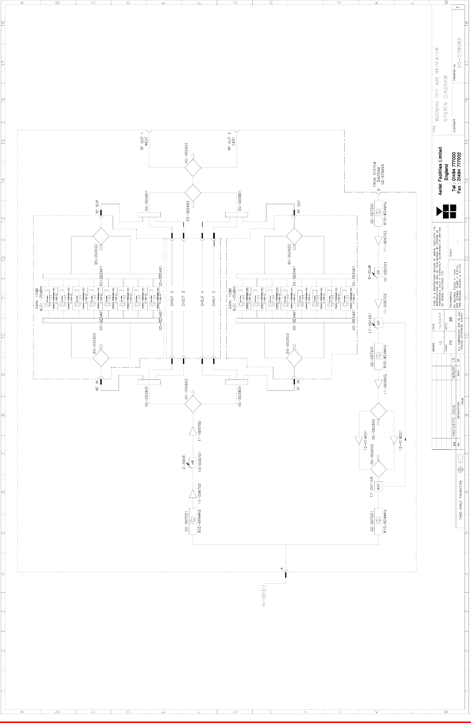
3.7.1 Description
This shelf is the interface between the system’s 800MHz bi-directional tunnel amplifiers and the off-air
antenna.
In the downlink direction, the incoming antenna RF is directed through a bandpass filter to a pair of
20dB gain low noise amplifiers that have a switchable 0-30dB attenuator between them. The resultant
single path is then divided several times and fed out of the shelf to the channel selective modules (x
24). When the outputs from the channel modules return, they are combined and exit to the two power
amplifier shelves that serve the East and West tunnel leaky feeders.
The uplink path originates from the tunnel antennas, and is band-selectively amplified and fed to a
pair of 10W power amplifiers. This final amplification stage in the uplink path has an automatic gain
control detector and attenuator to help negate the overloading effect of someone operating a mobile
close to the LCX tunnel antennas.
Note that this shelf has its own, dedicated mains driven, 12-15V DC PSU unit.
3.7.2 Technical Specification
PARAMETER SPECIFICATION
851-869MHz (Downlink)
Frequency range: 806-824MHz (Uplink)
Downlink output power: N/A
Uplink output power: 10Watts (x2)
AGC: Fitted in uplink path
AGC dynamic range: >35dB
Height: 8U
Width: 19" (482.6mm)
Shelf
dimensions Depth: <450mm (excluding connectors & handles)
operational: -20°C to +60°C Temperature
range storage: -40°C to +70°C
Weight: <15kg
Shelf gain: 60dB (typical)
Impedance: 50
Humidity: 5 – 95% non-condensing
RF Connectors: N type female
Environmental protection: IP44
Case: Alocrom 1200/Iridite NCP coating
Heatsinks: Black anodised aluminium
Handles: Silver anodised aluminium alloy
Finish
Fascia: Painted to RAL7035

Mission Valley Radio Repeater Equipment + Upgrade
User/Maintenance Handbook
Handbook No. 50-078021HBKM Page 20 of 85
3.7.3 Parts List
AFL Part # Part Description Qty.
02-007201 900MHz 8POLE 10-20MHz B/W SMA 4
05-002602 900MHz SPLITTER/COMBINER, 20W 5
05-003801 3WAY GEN.SPLIT 900MHz GEN.ASS 4
10-000701 1/4W0-30dB SWITCHED ATTENUATOR 2
11-005902 900MHz LOW NOISE AMP WITH RELAY ASS 3
11-006702 GA 800-1000MHz LNA 29dB (WITH RELAY 4
12-018001 PA 800-960MHz 10W 30dB 2
14-000225 CASE RAIL LONG R.S.A./R.F.A. 4
17-001109 CE AGC UNIT LOG DET/AMP ASSY (12V) 1
17-001201 C/E AGC UNIT ATTENUATOR ASSY 1
20-001601 12V RELAY BOARD 1
50-012820 CCE RACK MOUNTED 8U CHASSIS 1
50-012822 CCE RACK MOUNTED LID 1
50-012825 CCE RACK MOUNTED HEATSINK BRACKET 4
50-027720 RACK MTD CHAN C.E. MODIFIED HEATSIN 2
80-090822 C/E 8U FRONT PANEL, AFL (RAL7035) 1
80-310420 BCC 400W POWER SUPPLY HEATSINK 1
91-030002 N ADAPTOR PANEL FEMALE:FEMALE 4
91-130005 SMA BULKHEAD ADAPTOR F/F 12
91-500025 3 PIN RIGHT ANGLE FREE PLUG NC-X 3
91-510003 3 PIN R.ANGLE FREE SOC.NC-X. 3
91-510004 3 PIN PNL.MOUNT SOCKET NC-X 3
91-510032 20A SOCKET CONTACT PIN 4
91-520001 PWR MAINS INL FIXED/SOLD.TERMS 1
91-520005 MAINS LEAD 1
91-520010 MAINS RETAINING CLIP 1
91-600007 'D' 9 WAY BLACK SHELL 8
91-600014 'D' 9 WAY SOCKET S/B (NON FILTERED) 7
91-600015 'D' 9 WAY PLUG S/B (NON FILTERED) 1
91-660001 2W5 MIXED D TYPE SOCKET (7 WAY) 2
96-110034 FUSE HOLDER 16-30A, 32mm BODY 3
96-300057 15V 27A PSU 400W (XP BCC) 1
96-700034 LED RED 5mm IP67 INTEGRAL RES. 24V 1
96-700035 LED GREEN 5mm IP67 INTEGRAL RES 24V 1
96-900018 AC TRIP SWITCH (5 AMP M.C.B.) 2
97-400005 HANDLE TYPE H6802 3U [ALLOY] 2
99-200008 DANGER HIGH VOLTAGE LABEL 2’ x 2' 1
99-200017 CAUTION HEAVY LABEL 75 x 55mm 2
Mission Valley Radio Repeater Equipment + Upgrade
User/Maintenance Handbook
Handbook No. 50-078021HBKM Page 21 of 85
3.7.4 800MHz Off-Air Repeater System Diagram, Drg. # 50-078082
Mission Valley Radio Repeater Equipment + Upgrade
User/Maintenance Handbook
Handbook No. 50-078021HBKM Page 22 of 85
3.8 800MHz 8Ch. Channel Module Sub-Rack (50-078003)
3.8.P 800MHz Channel Module Sub-Rack Photographs
Photographs of this sub-rack are unavailable.
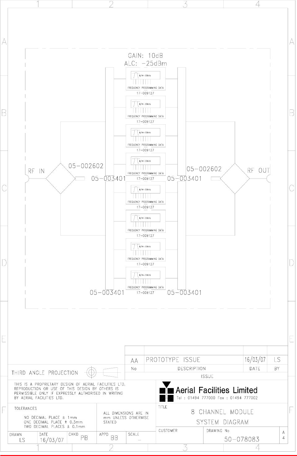
3.8.1 Description
The channel modules are built into a sub-rack which is the equivalent height of a 3U shelf. Each sub-
rack has eight channel selective modules (3 sub-racks=24 channels) and two channel control
modules that are DIP switch banks that configure the frequencies for the channel modules, see below
for channel module programming.
Each channel module has an alarm (alarm which is summed to form an overall alarm pair for the
whole sub-rack, that terminates at the rear-mounted 9-way alarm ‘D’ connector, pins 1 & 2.
3.8.2 Technical Specification
PARAMETER SPECIFICATION
855-869MHz (Downlink)
Frequency range: 810-824MHz (Uplink)
Height: 3U (equivalent)
Width: 19" (482.6mm)
Shelf
dimensions Depth: <400mm (excluding connectors & handles)
operational: -20°C to +60°C Temperature
range storage: -40°C to +70°C
Weight: <15kg
Channel module gain: 10dB
Channel module AGC level: -25dBm
Impedance: 50
DC power input: 12V @ 6.3A (fused)
Power consumption: <2.6Amps @ 12V DC
Humidity: 5 – 95% non-condensing
RF Connectors: N type female
Environmental protection: IP44
Case: Alocrom 1200/Iridite NCP coating
Heatsinks: None
Handles: None
Finish
Fascia: Painted to RAL7035

Mission Valley Radio Repeater Equipment + Upgrade
User/Maintenance Handbook
Handbook No. 50-078021HBKM Page 23 of 85
3.8.3 VHF/ UHF Programming Procedure
The operating frequency for each channel in the Cell Enhancer is programmed by 16 DIL (Dual In
Line) switches. The programming switches are mounted in the Channel Control Modules which are
located beside the channel modules in the module racking. The Channel Selectivity Modules are
connected to the Channel Control Module via 25 way ribbon cables.
Switch 16 is at the far left of the line of switches leading down to Switch 1 at the far right of the line.
Adjacent to the DIL switches for each channel is a toggle switch to turn on and off individual channels
as required. A green LED indicates the DC ON status of each channel.
A red LED shows the alarm condition for each channel. An illuminated alarm LED indicates that the
synthesiser has not achieved phase lock and that the module is disabled. There is a problem which
requires investigation, often a frequency programmed outside the operating frequency range.
The following information is necessary before attempting the programming procedure.
1) operating frequency
2) synthesiser channel spacing (step size)
3) synthesiser offset (IF)
Check that the required frequency falls within the operational frequency limits of the Cell Enhancer.
For each channel required, subtract the synthesiser offset from the required operating frequency and
record the resulting local oscillator frequency.
Divide each local oscillator frequency by the channel spacing and check that the result is an integer
(i.e.: no remainder).
If the synthesiser division ratio is not an integer value, check the required operational frequency and
repeat the calculation checking for mistakes.
Convert the required local oscillator frequency to synthesiser programming switch state patterns
according to the following table.
Switch number Synthesiser offset added when switch in UP position
1 +12.5kHz
2 +25kHz
3 +50kHz
4 +100kHz
5 +200kHz
6 +400kHz
7 +800kHz
8 +1.6MHz
9 +3.2MHz
10 +6.4MHz
11 +12.8MHz
12 +25.6MHz
13 +51.2MHz
14 +102.4MHz
15 +204.8MHz
16 +409.6MHz

Mission Valley Radio Repeater Equipment + Upgrade
User/Maintenance Handbook
Handbook No. 50-078021HBKM Page 24 of 85
3.8.4 VHF/ UHF Programming Example
Frequency required: 465.5MHz
Channel spacing: 12.5kHz
Synthesiser offset: 21.4MHz
The Local Oscillator frequency is therefore: 465.4 – 21.4 = 444.0 MHz
Dividing the LO frequency
by the channel spacing of: 0.0125MHz:
444.0 = 35520
0.0125
This is an integer value, therefore it is OK to proceed.
Switch settings
16 15 14 13 12 11 10 9 8 7 6 5 4 3 2 1
Local Oscillator
Frequency of:
444.0 MHz 1 0 0 0 1 0 1 0 1 1 0 0 0 0 0 0
Switch setting: 0 = switch DOWN (on, frequency ignored)
1 = switch UP (off, frequency added)

Mission Valley Radio Repeater Equipment + Upgrade
User/Maintenance Handbook
Handbook No. 50-078021HBKM Page 25 of 85
3.8.5 900MHz Programming Procedure
Check that the required downlink and uplink frequencies fall within the operational band limits of the
Cell Enhancer.
For each Downlink and Uplink channel frequency, subtract the appropriate synthesiser offset
frequency from the required operational frequency and record the resulting local oscillator
frequencies.
Divide each Downlink and Uplink local oscillator frequency by the synthesiser channel spacing and
check that the result is an integer (i.e. no remainder).
If the synthesiser division ratio is not an integer value, check the required operational frequency and
repeat the calculation checking for mistakes.
Convert the required local oscillator frequency to synthesiser programming switch state patterns
according to the following table.
NOTE: Ensure that the correct column is used from the table below according to the synthesiser
channel spacing of the particular channel modules fitted to the Cell Enhancer.
Synthesiser offset added when switch in UP position Switch
Number 25kHz channel spacing 100kHz channel spacing
1 +25kHz +100kHz
2 +50kHz +200kHz
3 +100kHz +400kHz
4 +200kHz +800kHz
5 +400kHz +1.6MHz
6 +800kHz +3.2MHz
7 +1.6MHz +6.4MHz
8 +3.2MHz +12.8MHz
9 +6.4MHz +25.6MHz
10 +12.8MHz +51.2MHz
11 +25.6MHz +102.4MHz
12 +51.2MHz +204.8MHz
13 +102.4MHz +409.6MHz
14 +204.8MHz +819.2MHz
15 +409.6MHz -
16 +819.2MHz -

Mission Valley Radio Repeater Equipment + Upgrade
User/Maintenance Handbook
Handbook No. 50-078021HBKM Page 26 of 85
3.8.6 Parts List
AFL Part # Part Description Qty.
05-003302 4 WAY SPLITTER GSM 900MHz 4
17-002101 CHANNEL CONTROL MODULE 2
17-002103 26WAY RIBBON CABLE LEAD 8
17-003022 MODULE PATTERNED LEAVE 8
17-003023 SUBRACK SIDE PANEL 4
17-003024 SUBRACK REAR BRACKET 8
17-003025 BOTTOM MODULE GUIDE 8
17-003028 MODULE SQUARE LEAVE 8
17-003029 TOP MODULE GUIDE 8
17-009127 CHAN MOD 810-860MHz 30KHz 8p TCXO 8
91-100004 SMA PLUG ELBOW UT-85/RG405 32
91-500001 POWER PLG 3 PIN PNL.MOUNT NC-X 2
91-510003 3 PIN R.ANGLE FREE SOC.NC-X. 2
91-600007 'D' 9 WAY BLACK SHELL 4
91-600014 'D' 9 WAY SOCKET S/B (NON FILTERED) 2
91-600015 'D' 9 WAY PLUG S/B (NON FILTERED) 2
92-280033 Captive Screw 16
96-110001 FUSE HOLDER 20 x 5mm 6.3A 2
96-110007 T 1.6A A.SURGE FUSE 20mm 4
97-000002 BLACK MODULE CAGE RUNNER 16
97-600001 SUBRACK FRONT HORIZ 4
97-600002 SUBRACK M2.5 STD TAP 4
Mission Valley Radio Repeater Equipment + Upgrade
User/Maintenance Handbook
Handbook No. 50-078021HBKM Page 27 of 85
3.8.7 8 Channel Module Shelf System Diagram, Drg. # 50-078083
Mission Valley Radio Repeater Equipment + Upgrade
User/Maintenance Handbook
Handbook No. 50-078021HBKM Page 28 of 85
3.9 800MHz 40Watt Power Amplifier/Driver Shelf (50-078004)
3.9.P 40Watt PA Shelf Photographs
Mission Valley Radio Repeater Equipment + Upgrade
User/Maintenance Handbook
Handbook No. 50-078021HBKM Page 29 of 85
3.9.1 Description
The 40Watt master site power amplifier shelf concerns itself with powering the 800MHz channel
information to the LCX tunnel antennas. The output from the channel module shelves is split into two
and input to each of the two PA shelves. Each PA powers either the East or West tunnel leaky feeder
antennas and a proportion of the LCX signal provides a feed to the 800MHz in-line amplifiers that
power the fire exit stairs antennas. All amplifiers in the shelf have alarms and they terminate at the
rear panel mounted 9-way ‘D’ connector, pins 1 & 2.
Since the Mission Valley system was first commissioned, the upgrade was designed and built using a
high power shelf (50-078005) instead of the 40Watt shelf described here. Therefore, this section is
shown for information only.
3.9.2 Technical Specification
PARAMETER SPECIFICATION
Frequency range: 855-869MHz
Downlink output power: 20-40Watts
AGC: N/A
Height: 8U
Width: 19" (482.6mm)
Shelf
dimensions: Depth: <450mm (excluding connectors & handles)
operational: -20°C to +60°C Temperature
range storage: -40°C to +70°C
Weight: <25kg
Shelf gain: 30dB (typical)
Impedance: 50
Humidity: 5 – 95% non-condensing
RF Connectors: N type female
Environmental protection: IP44
Case: Alocrom 1200/Iridite NCP coating
Heatsinks: Black anodised aluminium
Handles: Aluminium alloy
Finish
Fascia: Painted to RAL7035

Mission Valley Radio Repeater Equipment + Upgrade
User/Maintenance Handbook
Handbook No. 50-078021HBKM Page 30 of 85
3.9.3 Parts List
AFL Part # Part Description Qty.
02-007201 900MHz 8POLE 10-20MHz B/W SMA 1
05-002602 900MHz SPLITTER/COMBINER, 20W 2
10-000901 SW. ATTENUATOR 0.25W 0-15dB 1
11-005802 900MHz DRIVER STAGE WITH RELAY 1
12-018002 PA 800-960MHz 20W CLASS A 2
14-000225 CASE RAIL LONG R.S.A./R.F.A. 2
50-012820 CCE RACK MOUNTED 8U CHASSIS 1
50-012822 CCE RACK MOUNTED LID 1
50-012825 CCE RACK MOUNTED HEATSINK BRACKET 4
50-027720 RACK MTD CHAN C.E. MODIFIED HEATSIN 2
80-090822 C/E 8U FRONT PANEL, AFL (RAL7035) 1
80-310420 BCC 400W POWER SUPPLY HEATSINK 1
91-030002 N ADAPTOR PANEL FEMALE:FEMALE 2
91-510032 20A SOCKET CONTACT PIN 4
91-520001 PWR MAINS INL FIXED/SOLD.TERMS 1
91-520005 MAINS LEAD 1
91-520010 MAINS RETAINING CLIP 1
91-600007 'D' 9 WAY BLACK SHELL 1
91-600014 'D' 9 WAY SOCKET S/B (NON FILTERED) 1
91-600015 'D' 9 WAY PLUG S/B (NON FILTERED) 1
91-660001 2W5 MIXED D TYPE SOCKET (7 WAY) 2
96-300057 15V 27A PSU 400W (XP BCC) 1
96-700034 LED RED 5mm IP67 INTEGRAL RES. 24V 1
96-700035 LED GREEN 5mm IP67 INTEGRAL RES 24V 1
96-900018 AC TRIP SWITCH (5 AMP M.C.B.) 1
97-400005 HANDLE TYPE H6802 3U [ALLOY] 2
99-200008 DANGER HIGH VOLTAGE LABEL 2’ x 2' 1
99-200017 CAUTION HEAVY LABEL 75 x 55mm 2
Mission Valley Radio Repeater Equipment + Upgrade
User/Maintenance Handbook
Handbook No. 50-078021HBKM Page 31 of 85
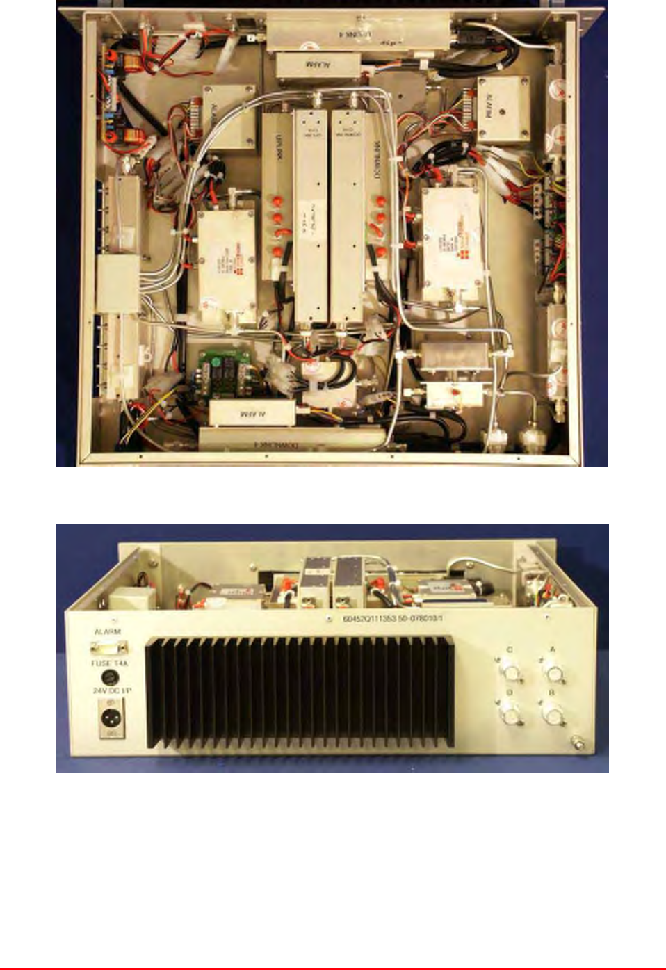
3.10 VHF Simplex Shelf (50-078010/1)
3.10.P VHF Simplex Shelf Photographs
Mission Valley Radio Repeater Equipment + Upgrade
User/Maintenance Handbook
Handbook No. 50-078021HBKM Page 32 of 85
3.10.1 Description
The VHF simplex shelves are two-path, single frequency cell enhancers that cut the DC power (and
thereby mute the amplifiers) to the opposing path whenever a signal is detected. This is achieved by
using highly accurate crystal filters to set the exact channel frequency and speciality channel selective
modules that react to detectors placed in each path. There are also switched attenuators before and
after the channel modules in order to accurately set the RF threshold levels for correct simplex
operation (this will already have been achieved at the time of final system test and should not need
adjustment). Isolators at the outputs of each path protect the power stages from potentially damaging
stray interference from other channels.
Each amplifier in the simplex CE shelves has an alarm as do the channel modules and the summary
alarms terminate at the rear panel mounted 9-way ‘D’ connector, pins 1 & 2.
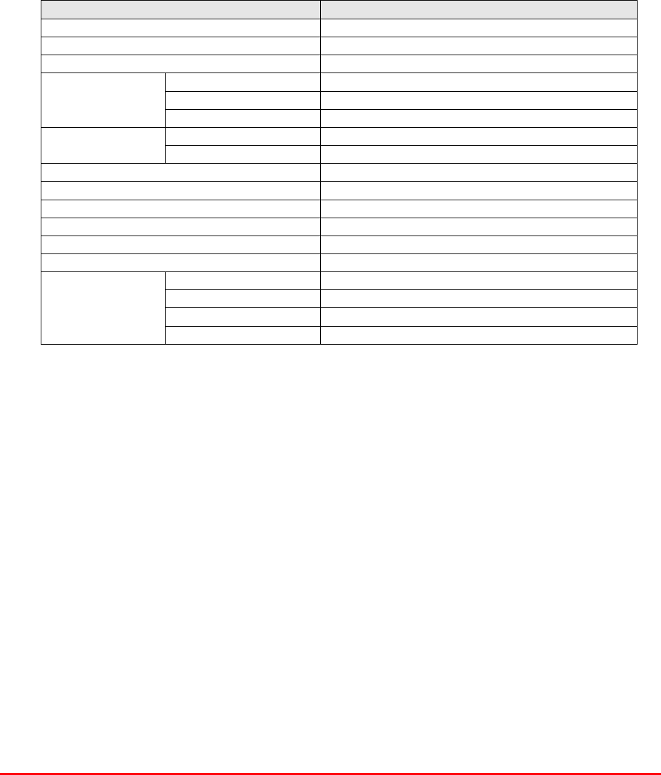
3.10.2 Technical Specification
PARAMETER SPECIFICATION
161.295MHz (50-078010/1)
Simplex frequencies: 159.0-161.0MHz (50-078010/2)
Gain: >90dB
Gain Adjustment: 0 – 15dB (in 1dB step)
Uplink Power: >5.0Watts (typical)
Downlink Power: >5.0Watts (typical)
Uplink: +48dBm
IP3 Downlink: +48dBm
Noise Figure: <6dB
23dB (downlink)
Channel module gain: 24dB (uplink)
VSWR: better than 1.5:1
RF Connectors: N type, female
operational: -20°C to +60°C
Temperature
range storage: -40°C to +70°C
Case: Alocrom 1200/Iridite NCP coating
Heatsinks: Black anodised aluminium
Handles: Aluminium alloy
Finish
Fascia: Painted to RAL7035
1 U/L amplifiers
2 D/L amplifiers
Alarms Fitted
(volt-free contacts/TTL) 3 Channel modules

Mission Valley Radio Repeater Equipment + Upgrade
User/Maintenance Handbook
Handbook No. 50-078021HBKM Page 33 of 85
3.10.3 Parts List
AFL Part # Part Description Qty.
08-930002 2 PORT ISOLATOR 150-300MHz SMA 2
10-000901 SW. ATTENUATOR 0.25W 0-15dB 4
11-001202 10/600MHz LNA 24v SMA Alarm 7
12-002213 3 STAGE ALARM/SIMPLEXMUTE PCB SUB-ASS 2
12-002220 3 STAGE ALARM PCB COVER 2
12-002804 SINGLE CH. ALARM/SIMPLEX MUTE BOARD 7
12-002820 SINGLE CHANNEL ALARM COVER 7
12-004902 POWER AMP VHF 5W CLASS AB 2
13-001803 DUAL DC/DC CONVERTER 24V-12V 1A 1
13-001822 DC-DC CON 24V-5V/15V COVER 1
13-002811 SIMPLEX CONTROLLER PCB ASSEMBLY 2
17-001201 C/E AGC UNIT ATTENUATOR ASSY 4
17-002802 SIMPLEX C.E Rx/SQUELCH & AF (SMD) 2
17-009135 VHF 15Kstep CH MOD 15kHz 8P BW+IFRX 2
19-000826 2U,3U,4U 19" UNIT 400 DEEP LID 1
19-000921 3U 19" UNIT 400 DEEP CHASSIS + BKT 1
19-000924 3U 19" UNIT FRONT PANEL FAB 1
80-063920 HEATSINK 2U ASS140 (5W) 2
91-030002 N ADAPTOR PANEL FEMALE:FEMALE 4
91-500001 POWER PLG 3 PIN PNL.MOUNT NC-X 1
91-510003 3 PIN R.ANGLE FREE SOC.NC-X. 1
91-600001 'D'TYPE 9 WAY PLUG S/B TERM 1
91-600014 'D' 9 WAY SOCKET S/B (NON FILTERED) 2
91-620001 'D' 25 WAY SOCKET S/B TERM 2
91-700017 ICD 15 WAY 0.1' CONNECTOR 9
93-540035 1K3 0.25W 1% RES MRS25 M:F 2
*93-980109 161.295MHz CRYSTAL FILT FAN4M52500 4
**93-980112 160.530MHz CRYSTAL FILT FAN4M52500 4
96-110001 FUSE HOLDER 20 x 5mm6.3A 1
96-300014 PSU VOLTS ADJUSTER 2
96-700017 LED AMBER 5mm SEALED IP66 2
96-700034 LED RED 5mm IP67 INTEGRAL RES. 24V 1
96-700035 LED GREEN 5mm IP67 INTEGRAL RES 24V 1
97-400005 HANDLE TYPE H6802 3U [ALLOY] 2
* = Frequency selective crystal (50-078010/1 shelf)
** = Frequency selective crystal (50-078010/2 shelf)
Mission Valley Radio Repeater Equipment + Upgrade
User/Maintenance Handbook
Handbook No. 50-078021HBKM Page 34 of 85
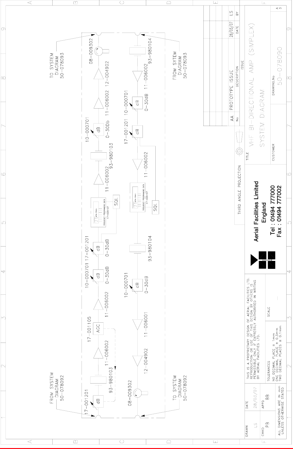
3.10.4 VHF Shelf System Diagram, Drg. # 50-078090
Mission Valley Radio Repeater Equipment + Upgrade
User/Maintenance Handbook
Handbook No. 50-078021HBKM Page 35 of 85
3.11 VHF Simplex Shelf (50-078010/2)
This second VHF simplex shelf is hardware identical to the previously described shelf (50-07801/1) in
section 3.10 except for the crystal filters used to set the channel frequency.
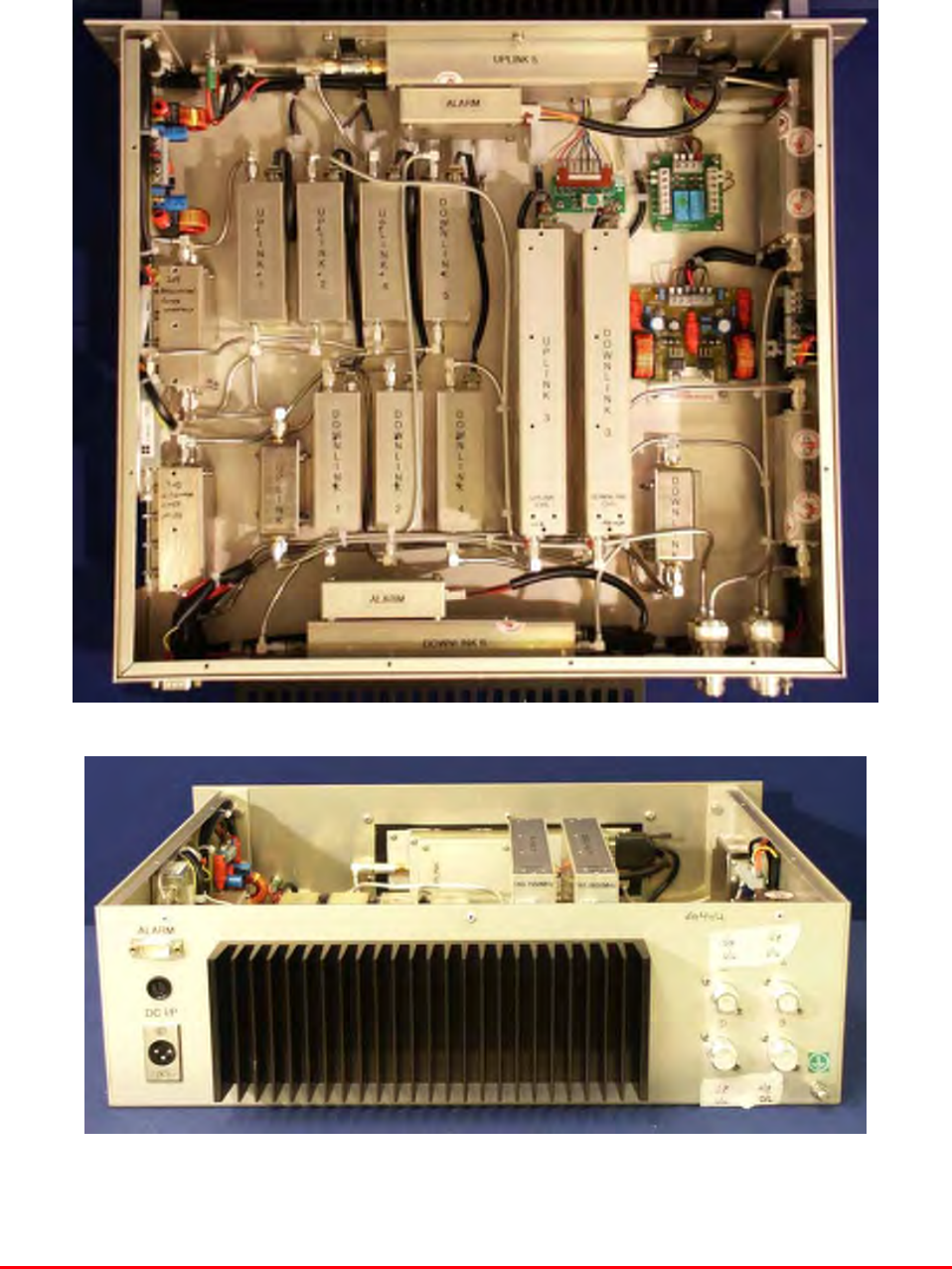
3.12 VHF Duplex Shelves (50-078011/1-4)
3.12.P Duplex Shelf Photographs
There are four different types of duplex shelves 50-078011/1,2,3 & 4 they differ only in the
frequencies they process.
Mission Valley Radio Repeater Equipment + Upgrade
User/Maintenance Handbook
Handbook No. 50-078021HBKM Page 36 of 85
3.12.1 Description
The duplex shelves are part of the VHF amplification system and like the simplex shelves, have
crystal filters instead of bandpass filters to set frequencies and bandwidths. There are two downlink
channels and two uplink channels, the downlink paths having isolators fitted to each of the 5Watt
output stages to prevent interfering reflections from the other channel.
The uplink channel modules have a dedicated noise muting circuit fitted externally to the channel
module which operates when the downlink path is active.
All amplifiers have built-in alarms which are configured as a summary, volt-free relay contact pair
terminating at pins 1 & 2 on the rear panel mounted ‘D’ type alarm connector.
3.12.2 Technical Specification
PARAMETER SPECIFICATION
160.665MHz (50-078011/1, D/L)
160.935MHz (50-078011/1, U/L)
160.380MHz (50-078011/2, D/L)
160.905MHz (50-078011/2, U/L)
160.710MHz (50-078011/3, D/L)
161.415MHz (50-078011/3 U/L)
161.565MHz (50-078011/4, D/L)
Duplex channel frequencies:
160.755MHz (50-078011/4 U/L)
Gain: >90dB
Gain Adjustment: 0 – 15dB (in 1dB steps, both paths)
Uplink Power: >5.0Watts
Downlink Power: >5.0Watts
Uplink: +48dBm
IP3 Downlink: +48dBm
Noise Figure: <6dB
AGC level: -2dBm (uplink & downlink)
23dB (downlink)
Channel module gain: 24dB (uplink)
VSWR: better than 1.5:1
RF Connectors: N type, female
operational: -20°C to +60°C
Temperature range storage: -40°C to +70°C
Case: Alocrom 1200/Iridite NCP coating
Heatsinks: Black anodised aluminium
Handles: Aluminium alloy
Finish
Fascia: Painted to RAL7035
1 U/L amplifiers
2 D/L amplifiers
Alarms Fitted:
(volt-free contacts/TTL) 3 Channel modules

Mission Valley Radio Repeater Equipment + Upgrade
User/Maintenance Handbook
Handbook No. 50-078021HBKM Page 37 of 85
3.12.3 Parts List
AFL Part # Part Description Qty.
08-930002 2 PORT ISOLATOR 150-300MHz SMA 2
10-000901 SW. ATTENUATOR 0.25W 0-15dB 4
11-006002 LNA VHF 70-500MHz WITH RELAY 7
12-002201 3 STAGE AMPLIFIER ALARM BOARD 1
12-002203 3 STAGE ALARM BOARD SIMPLEX 1
12-002220 3 STAGE ALARM PCB COVER 2
12-004902 POWER AMP VHF 5W CLASS AB 2
13-001803 DUAL DC/DC CONVERTER 24V-12V 1A 2
13-001822 DC-DC CON 24V-5V/15V COVER 1
13-002812 SWITCH VERSION OF SIMPLEX CONT. 1
17-001105 CE AGC UNIT LOG DET/AMP ASSY (24V) 1
17-009135 VHF 15K step CH MOD 15kHz 8p BW+IFRX 2
19-000826 2U,3U,4U 19" UNIT 400 DEEP LID 1
19-000921 3U 19" UNIT 400 DEEP CHASSIS + BKT 1
19-000924 3U 19" UNIT FRONT PANEL FAB 1
80-063920 HEATSINK 2U ASS140 (5W) MILCHBUCK 2
91-030002 N ADAPTOR PANEL FEMALE:FEMALE 4
91-500001 POWER PLG 3 PIN PNL.MOUNT NC-X 1
91-510003 3 PIN R.ANGLE FREE SOC.NC-X. 1
91-600001 'D'TYPE 9 WAY PLUG S/B TERM 1
91-600014 'D' 9 WAY SOCKET S/B (NON FILTERED) 7
91-620001 'D' 25 WAY SOCKET S/B TERM 2
91-700017 ICD 15 WAY 0.1' CONNECTOR 2
96-110001 FUSE HOLDER 20 x 5mm 6.3A 1
96-700034 LED RED 5mm IP67 INTEGRAL RES. 24V 1
96-700035 LED GREEN 5mm IP67 INTEGRAL RES 24V 1
97-400005 HANDLE TYPE H6802 3U [ALLOY] 2
*93-980103 160.665MHz CRYSTAL FILT FAN4M52500 2
*93-980104 160.935MHz CRYSTAL FILT FAN4M52500 2
*93-980105 160.380MHz CRYSTAL FILT FAN4M52500 2
*93-980106 160.905MHz CRYSTAL FILT FAN4M52500 2
*93-980107 160.710MHz CRYSTAL FILT FAN4M52500 2
*93-980108 161.415MHz CRYSTAL FILT FAN4M52500 2
*93-980110 161.565MHz CRYSTAL FILT FAN4M52500 2
*93-980111 160.755MHz CRYSTAL FILT FAN4M52500 2
* These frequency selection crystals are different for each VHF duplex Cell Enhancer shelf.
Mission Valley Radio Repeater Equipment + Upgrade
User/Maintenance Handbook
Handbook No. 50-078021HBKM Page 38 of 85
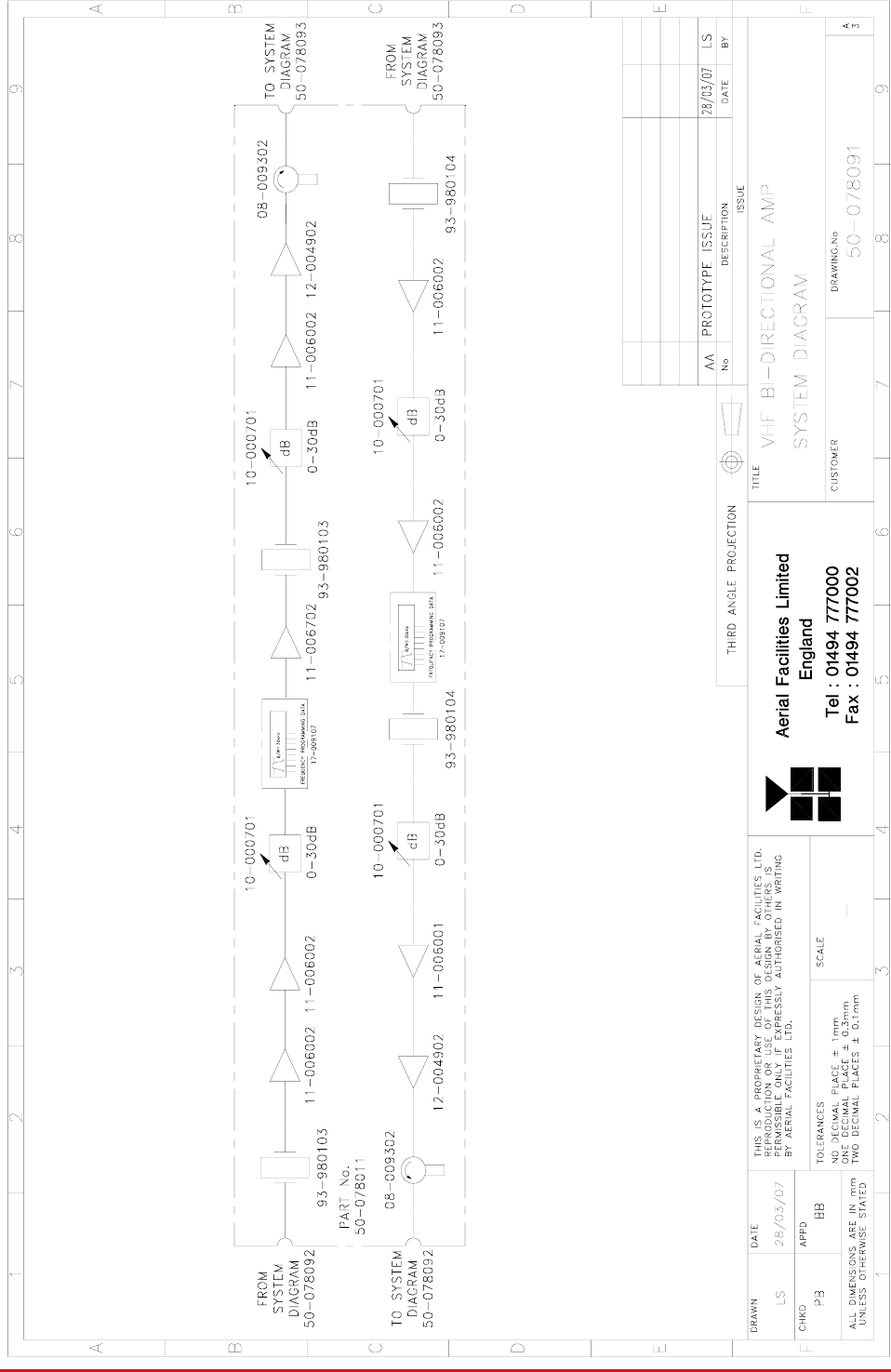
3.12.4 VHF Duplex Shelf System Diagram, Drg. # 50-078091
Mission Valley Radio Repeater Equipment + Upgrade
User/Maintenance Handbook
Handbook No. 50-078021HBKM Page 39 of 85
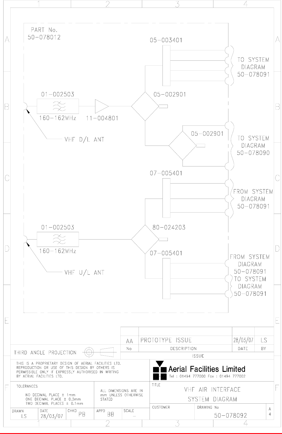
3.13 VHF Air Interface Shelf (50-078012)
3.13.1 Description
The VHF system is provided with three Yagi off-air antennas, two downlink, receiving downlink signals
from two different directions, and one uplink, facing the nearest BTS. Bandpass filters exclude
extraneous noise on the frequency bands to be processed and once filtered, the downlink signal is
amplified (10dB gain) and separately split to the simplex and duplex shelves’ inputs. The uplink
outputs from these six VHF shelves are combined, filtered and sent directly to the uplink off-air Yagi
antenna. The downlink low-noise-amplifier has an alarm, configured as a summary, volt-free relay
contact pair terminating at pins 1 & 2 on the ‘D’ type alarm connector.
3.13.2 Technical Specification
PARAMETER SPECIFICATION
Frequency range: 160-162MHz (D/L, U/L)
VSWR: better than 1.5:1
Shelf size: 3U
Insertion loss: <1.5dB
Rejection: >30dB
RF connectors: N type, female
operational: -20°C to +60°C
Temperature
range storage: -40°C to +70°C
Case: Alocrom 1200/Iridite NCP
Heatsinks: None
Handles: Aluminium alloy
Finish
Fascia: Painted to RAL 7035
Alarms Fitted: ‘D’ connector, pins 1& 2
3.13.3 Parts List
AFL Part # Part Description Qty.
01-002503 FILTER VHF H/B 6 SMA S 100W 2
05-002901 3dB BROADBAND SPLITTER SMA 1WATT 2
05-003401 4 WAY SPLITTER LOW POWER 1
07-005401 160-470MHz 3 WAY SPLITTER 2
11-004802 450MHz (10dB GAIN) LNA 12V. 1
12-002801 SINGLE CHANNEL ALARM BOARD STD 1
13-001803 DUAL DC/DC CONVERTER 24V-12V 1A 1
19-000826 2U,3U,4U 19" UNIT 400 DEEP LID 1
19-000921 3U 19" UNIT 400 DEEP CHASSIS + BKT 1
80-024203 TRANSMITTER HYBD COUPL.3 PORT 1
80-063627 3U FRONT PANEL FOR H/S 80-063920 1
91-030002 N ADAPTOR PANEL FEMALE:FEMALE 15
91-500001 POWER PLG 3 PIN PNL.MOUNT NC-X 1
91-510003 3 PIN R.ANGLE FREE SOC.NC-X. 1
91-700017 ICD 15 WAY 0.1' CONNECTOR 6
93-540035 1K3 0.25W 1% RES MRS25 M:F 2
96-110001 FUSE HOLDER 20 x 5mm6.3A 1
96-700034 LED RED 5mm IP67 INTEGRAL RES. 24V 1
96-700035 LED GREEN 5mm IP67 INTEGRAL RES 24V 1
97-400005 HANDLE TYPE H6802 3U [ALLOY] 2
Mission Valley Radio Repeater Equipment + Upgrade
User/Maintenance Handbook
Handbook No. 50-078021HBKM Page 40 of 85
3.13.4 VHF Air Interface Shelf System Diagram, Drg. # 50-078092
Mission Valley Radio Repeater Equipment + Upgrade
User/Maintenance Handbook
Handbook No. 50-078021HBKM Page 41 of 85
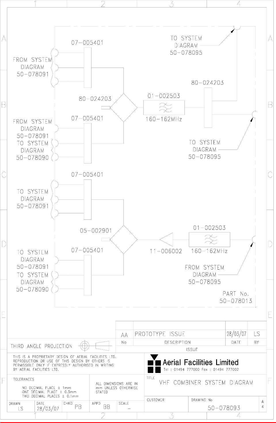
3.14 VHF Combiner Shelf (50-078013)
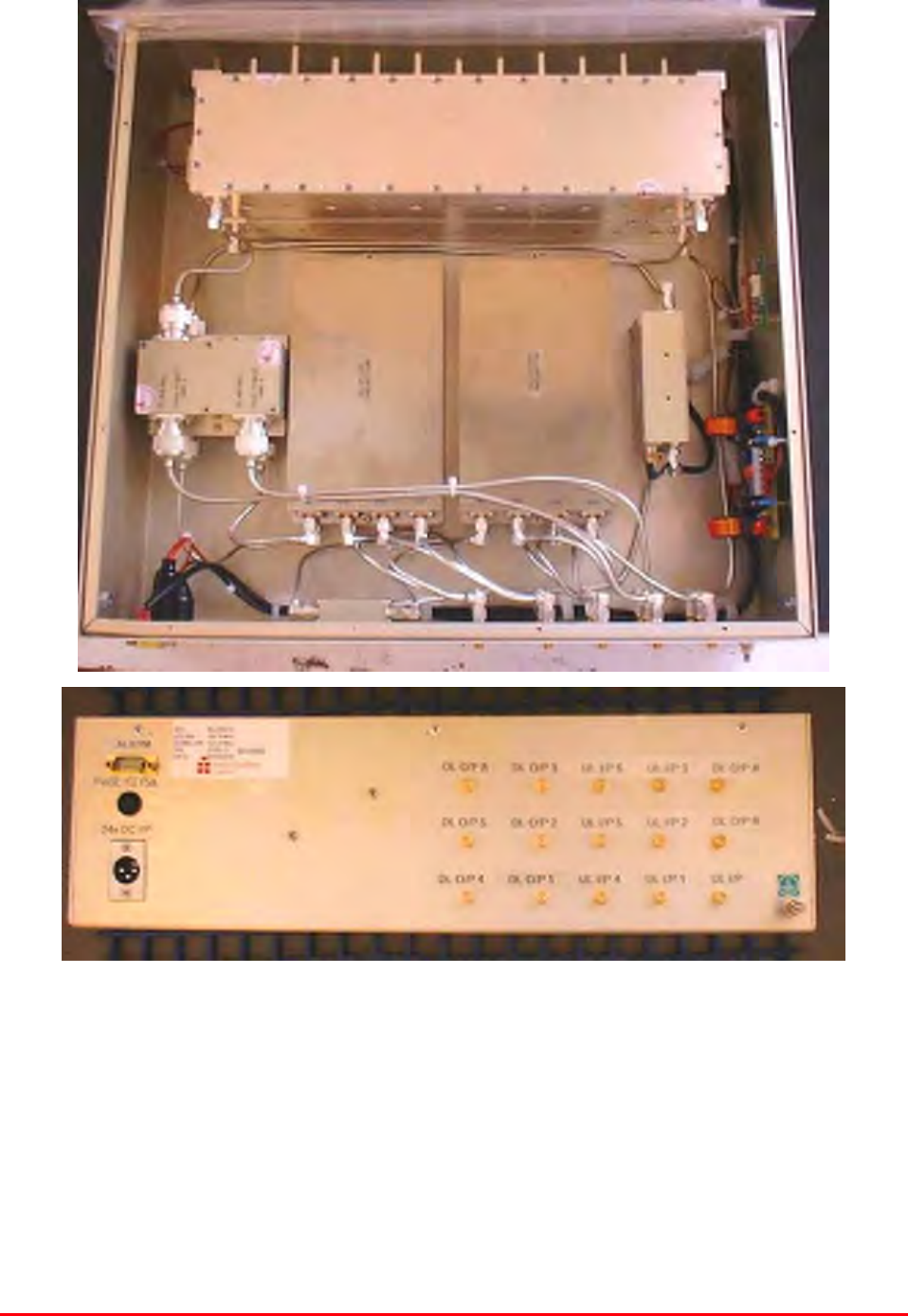
3.14.P VHF Combiner Photographs
Mission Valley Radio Repeater Equipment + Upgrade
User/Maintenance Handbook
Handbook No. 50-078021HBKM Page 42 of 85
3.14.1 Description
The purpose of the VHF combiner is to take the downlink products of all the VHF shelves and
combine them together so that they may, in turn, be combined with the 800MHz signals from the
cellular amplifiers to feed the tunnel antennas. The reverse is true of the uplink path where the VHF
signals from each of the tunnel antennæ are coupled from the 800MHz signals, filtered, amplified,
combined and then split equally for the inputs of the VHF uplink amplifiers.
The uplink low-noise-amplifier used in the shelf, has an alarm pair, configured as a summary, volt-free
relay contact pair terminating at pins 1 & 2 on the ‘D’ type alarm connector.
3.14.2 Technical Specification
PARAMETER SPECIFICATION
Frequency ranges: 160-162MHz (D/L, U/L)
VSWR: better than 1.5:1
Shelf size: 3U
Uplink amplifier gain: 20dB (typical)
Rejection: >30dB
RF connectors: N type, female
operational: -20°C to +60°C
Temperature
range storage: -40°C to +70°C
Case: Alocrom 1200/Iridite NCP
Heatsinks: None
Handles: Aluminium alloy
Finish
Fascia: Painted to RAL 7035
Alarms Fitted: ‘D’ connector, pins 1& 2
3.14.3 Parts List
AFL Part # Part Description Qty.
01-002503 FILTER VHF H/B 6 SMA S 100W 2
05-002901 3dB BROADBAND SPLITTER SMA 1WATT 1
07-005401 160-470MHz 3 WAY SPLITTER 4
11-006002 LNA VHF 70-500MHz WITH RELAY 1
13-001803 DUAL DC/DC CONVERTER 24V-12V 1A 1
19-000826 2U,3U,4U 19" UNIT 400 DEEP LID 1
19-000921 3U 19" UNIT 400 DEEP CHASSIS + BKT 1
80-024203 TRANSMITTER HYBD COUPL.3 PORT 2
80-063627 3U FRONT PANEL FOR H/S 80-063920 1
91-030002 N ADAPTOR PANEL FEMALE:FEMALE 15
91-500001 POWER PLG 3 PIN PNL.MOUNT NC-X 1
91-510003 3 PIN R.ANGLE FREE SOC.NC-X. 1
93-540035 1K3 0.25W 1% RES MRS25 M:F 2
96-110001 FUSE HOLDER 20 x 5mm6.3A 1
96-700034 LED RED 5mm IP67 INTEGRAL RES. 24V 1
96-700035 LED GREEN 5mm IP67 INTEGRAL RES 24V 1
97-400005 HANDLE TYPE H6802 3U [ALLOY] 2
Mission Valley Radio Repeater Equipment + Upgrade
User/Maintenance Handbook
Handbook No. 50-078021HBKM Page 43 of 85
3.14.4 VHF Combiner Shelf System Diagram, Drg. # 50-078093
Mission Valley Radio Repeater Equipment + Upgrade
User/Maintenance Handbook
Handbook No. 50-078021HBKM Page 44 of 85
3.15 VHF PSU Shelf (50-078014)
3.15.P VHF PSU Photographs
Mission Valley Radio Repeater Equipment + Upgrade
User/Maintenance Handbook
Handbook No. 50-078021HBKM Page 45 of 85
3.15.1 Description
The power supply shelves are separate for the VHF/UHF and 800MHz cell enhancers. The VHF/UHF
supply shelf is a 24V DC shelf which supplies six, 24Volt XLR type connector outputs at a maximum
total output power of 800Watts DC. These DC outputs are fused at a 10Amp rating although four of
the six DC outputs will be drawing less than 5Amps each at any one time.
3.15.2 Technical Specification
PARAMETER SPECIFICATION
Input: 110V AC @50/60Hz (single port)
Outputs: 6 x 24V DC @ 10A each (fused)
Front panel indicators: (x 2) Green LED for ‘PSU1/PSU2 ON’’
Fuses: 1 x 10A each outlet socket
DC Socket: XLR
operational: -20°C to +60°C
Temperature range storage: -40ºC to +70ºC
Case: Alocrom 1200/Iridite NCP coating
Heatsinks: Black anodised aluminium
Handles: Aluminium alloy
Finish
Fascia: Painted to RAL7035
Alarmed devices: Either PSU failure
Alarm interface (volt-free contacts): ‘D’ type alarm connector, pins 1 & 2
MTBF: >50,000 hours
Earthing: M8 stud
3.15.3 Parts List
AFL Part # Part Description Qty.
13-003301 MAINS FILTER 8AMP ASSEMBLY 1
20-001602 24V RELAY BOARD 1
80-008920 DUAL PSU HEATSINK 2
80-008921 DUAL PSU CASE 1
80-008922 DUAL PSU LID 1
80-008925 DUAL PSU FRONT PANEL 1
80-020632 2U CHASSIS LID FIXING RAIL 4
91-500025 3 PIN RIGHT ANGLE FREE PLUG NC-X 6
91-510004 3 PIN PNL.MOUNT SOCKET NC-X 6
91-510035 3 WAY MATE N LOK PLUG HOUSING 2
91-520001 PWR MAINS INL FIXED/SOLD.TERMS 1
91-520005 MAINS LEAD 1
91-520010 MAINS RETAINING CLIP 1
91-520032 MATE N LOK SOCKET CONTACT 20/14 AWG 6
91-600015 'D' 9 WAY PLUG S/B (NON FILTERED) 1
91-800014 3 WAY TERMINAL BLOCK 1
94-100004 STPS12045TV 60A DUAL DIODE 1
96-100001 20 x 5mm,10A FUSE HOLDER/CARRIER 6
96-300054 24V 17A PSU 400W (XP BCC) 2
96-600001 INSULATING BOOT LARGE 1
96-700035 LED GREEN 5mm IP67 INTEGRAL RES 24V 2
96-900017 AC TRIP SWITCH (3 AMP M.C.B.) 2
97-400002 HANDLE TYPE H6803 4U.[ALLOY] 2
Mission Valley Radio Repeater Equipment + Upgrade
User/Maintenance Handbook
Handbook No. 50-078021HBKM Page 46 of 85
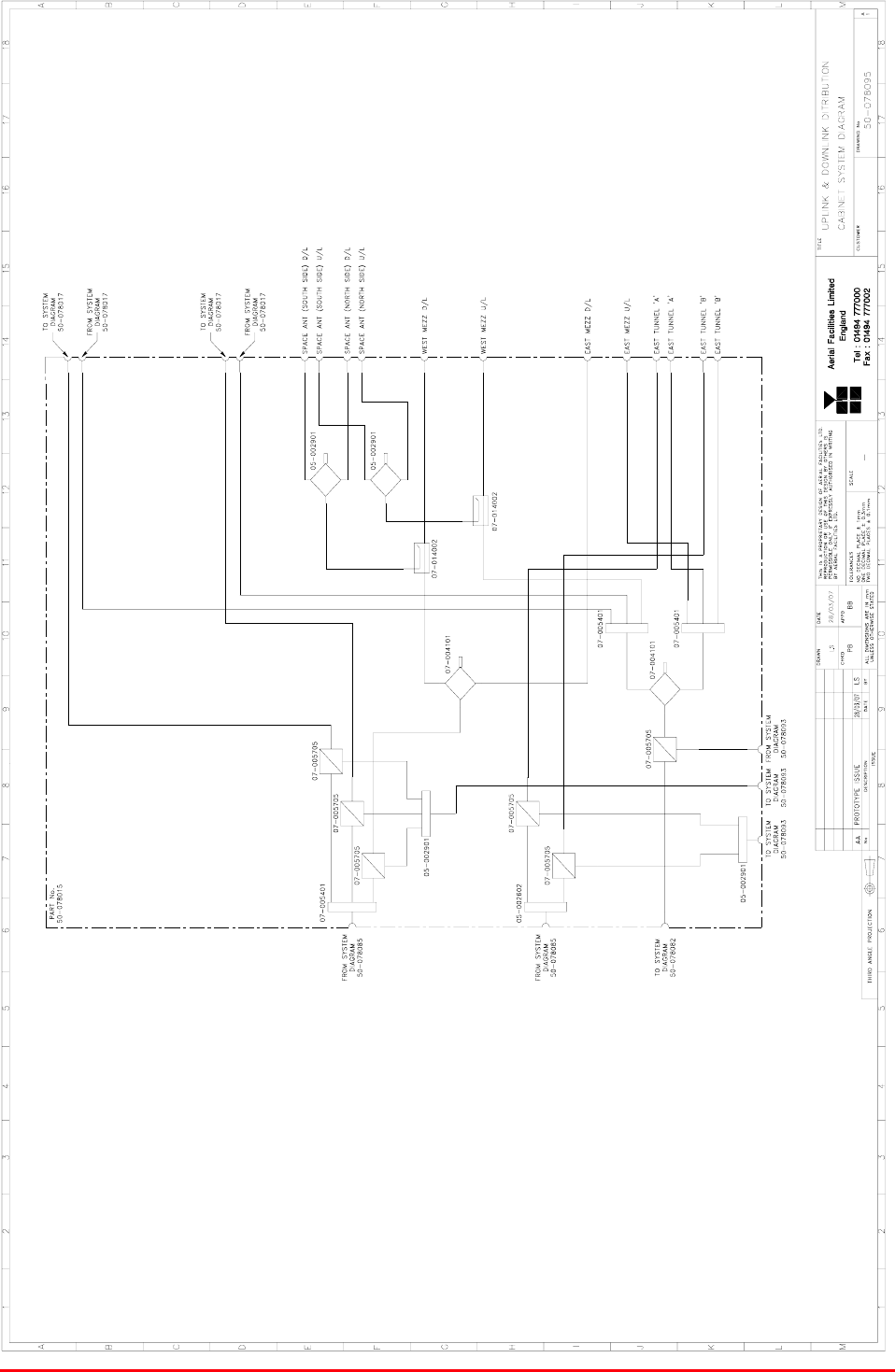
3.16 VHF/800MHz Tx Multi-coupler (50-078015)
3.16.1 Description
The multi-coupler shelf interfaces the VHF/UHF and 800MHz power output signals together to drive
the downlink Tx antennas and to receive the low-level signals from the uplink antennas prior to their
amplification and re-broadcast bask to the BTS.
This purely passive shelf is a mix of hybrid, cross-band and directional couplers which pass the
downlink signals with as little insertion loss as possible and the uplink signals with as good
isolation/rejection as possible. This shelf has no power source and no alarms.
3.16.2 Technical Specification
PARAMETER SPECIFICATION
Frequency ranges: 160-162MHz (D/L, U/L)
VSWR: better than 1.5:1
Shelf size: 5U
Rejection: >30dB
RF connectors: N type, female
operational: -20°C to +60°C
Temperature
range storage: -40°C to +70°C
Case: Alocrom 1200/Iridite NCP
Heatsinks: None
Handles: Aluminium alloy
Finish
Fascia: Painted to RAL 7035
Alarms Fitted: ‘D’ connector, pins 1& 2
3.16.3 Parts List
AFL Part # Part Description Qty.
05-001402 3 CH. WILK COMB. 1W LOW PWR VHF 1
05-002602 900MHz SPLITTER/COMBINER, 20W 1
05-002901 3dB BROADBAND SPLITTER SMA 1WATT 3
05-003801 3WAY GEN.SPLIT 900MHz GEN.ASS 1
07-004101 70-1000MHz 3dB SPLITTER/COMBINER 1
07-005401 160-470MHz 3 WAY SPLITTER 2
07-005705 CROSSBAND CPLR XC 250/380 SMA 6
07-014002 6dB 170-2200MHz DIRECTIONAL COUPLE 2
19-001122K 5U CHASSIS KIT (450mm deep) 1
80-024203 TRANSMITTER HYBD COUPL.3 PORT 1
91-030002 N ADAPTOR PANEL FEMALE:FEMALE 16
91-130005 SMA BULKHEAD ADAPT. F/F 6
Mission Valley Radio Repeater Equipment + Upgrade
User/Maintenance Handbook
Handbook No. 50-078021HBKM Page 47 of 85
3.16.4 Tx Multi-coupler System Diagram, Drg. # 50-078095
Mission Valley Radio Repeater Equipment + Upgrade
User/Maintenance Handbook
Handbook No. 50-078021HBKM Page 48 of 85
4. BAND SELECTIVE BI-DIRECTIONAL LINE AMPLIFIER
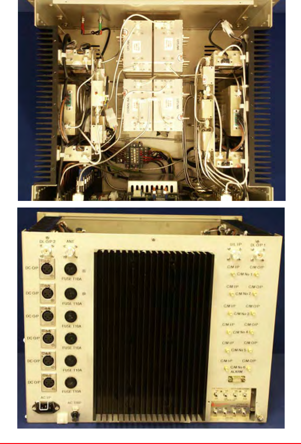
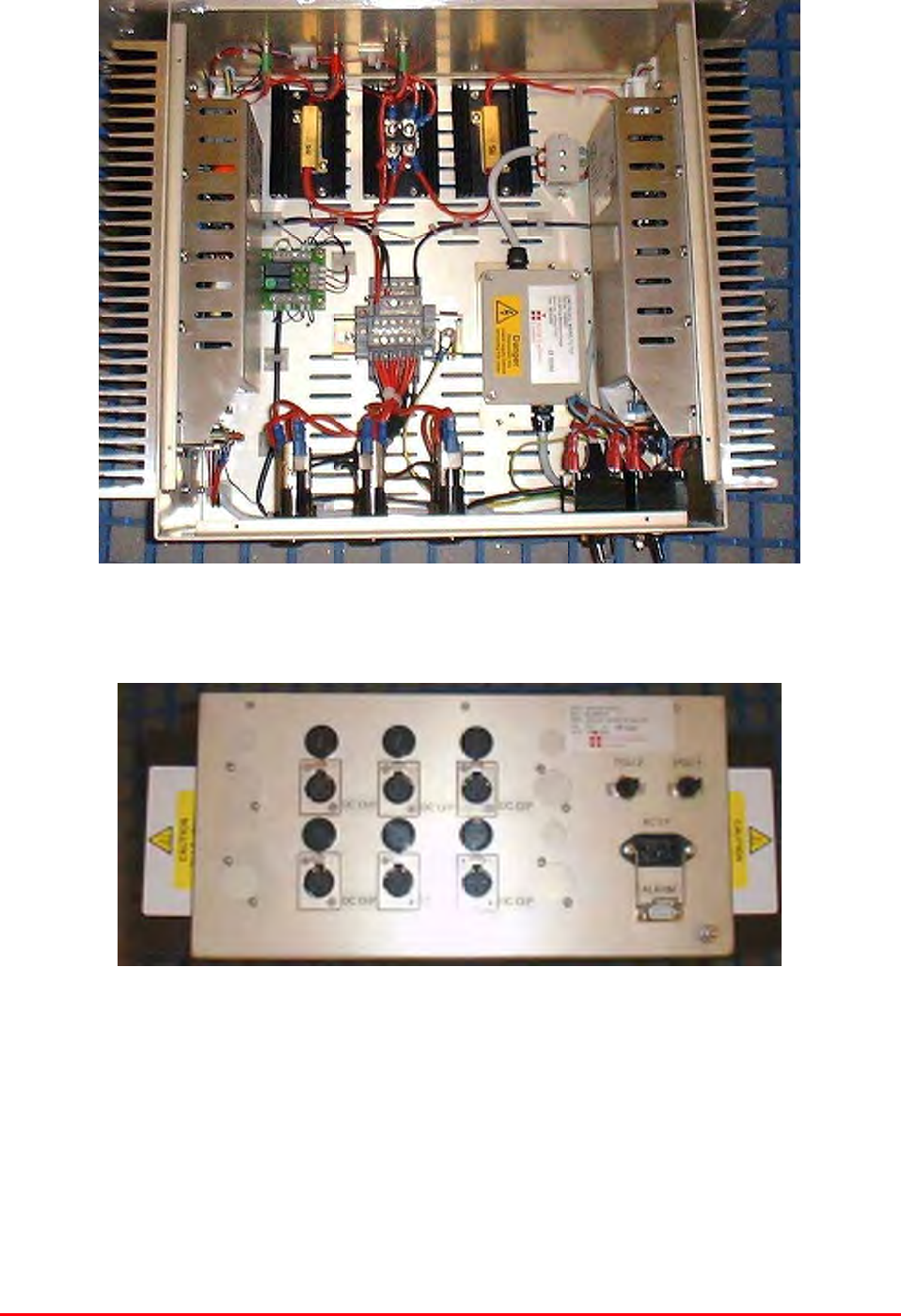
4.1 BDA Wall Assembly (50-078017)
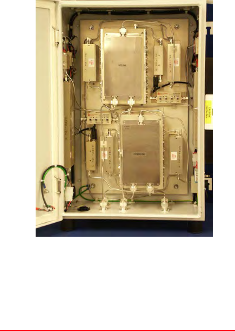
4.1.P BDA Assembly Photograph
View of Wall Case Internal (door open)

Mission Valley Radio Repeater Equipment + Upgrade
User/Maintenance Handbook
Handbook No. 50-078021HBKM Page 49 of 85
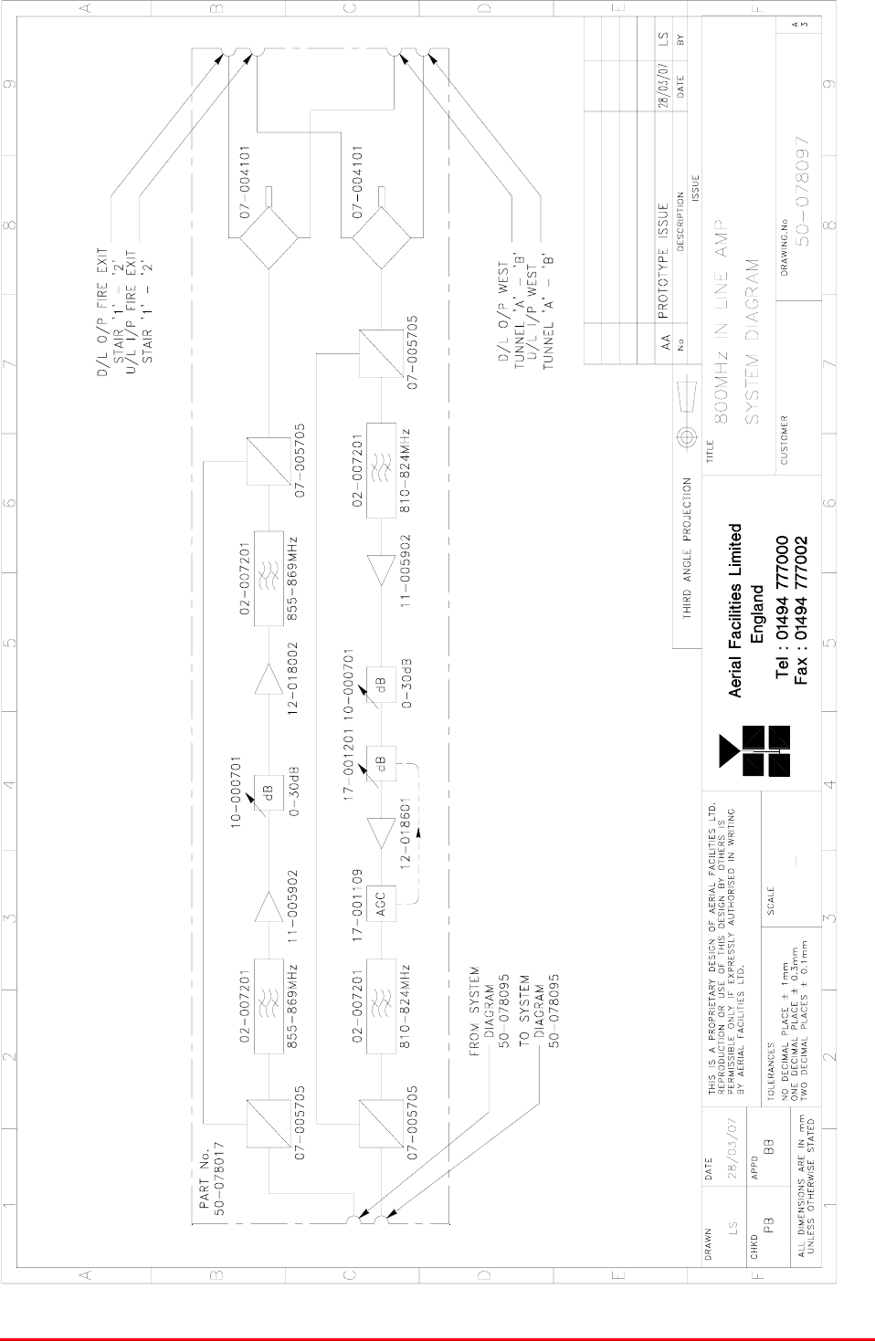
4.1.1 Description
The wall mounted tunnel BDA is a band-selective unit which draws its RF from the tunnel leaky feeder
coaxial cable, feeding separate down and uplink ports and operating in the 800MHz frequency region
with a cross-band coupled bypass to allow VHF signals to be passed through the amplifier with just a
small loss. (The loss at 800MHz is considerable compared with the VHF signals, so a small amount of
gain at 800MHz is required to overcome these losses, whereas the VHF signals need no boosting).
The primary application for the BDA is to boost the 800MHz and VHF signals in areas of the West
Tunnel and Fire Exits where coverage would otherwise be inadequate. Notice that each path has
automatic gain control as the amplifier receives its input from the leaky feeder antennas for both up
and downlink. This means that the signal could have large differences in level at any time which is
why the AGC is needed on both paths.
The amplifier needs 12V DC for its supply, and this enters from the BBU unit through a rugged
connector mounted on the R.H.S (viewed from front) of the case. For further notes on the use of the
battery backup system, see the dedicated BBU handbook at the end of this document (appendix B).
4.1.2 Electrical Specification
PARAMETER SPECIFICATION
855-869MHz (Downlink)
Frequency range: 810-824MHz (Uplink)
Bandwidth: 14MHz (both paths)
Rejection @ opposite band: 70dBc
Rejection @ 837.5MHz: 50dBc
Gain: >30dB
Gain Adjustment: 0 - 30dB (in 2dB steps)
Uplink 1 dB compression point: +37dBm
Downlink 1 dB compression point: +42dBm
Uplink +44dBm
IP3 Downlink +54dBm
Noise Figure: <8dB
+32dBm (uplink)
AGC level: +33.5dBm (downlink)
VSWR: better than 1.5:1
RF Connectors: N type, female
Impedance: 50
Alarms Fitted:
(volt-free contacts) 1 Amplifiers

Mission Valley Radio Repeater Equipment + Upgrade
User/Maintenance Handbook
Handbook No. 50-078021HBKM Page 50 of 85
4.1.3 Mechanical Specification
PARAMETER SPECIFICATION
Height: 620mm
Width: 420mm
Case size
Depth: 250mm
(excluding heatsinks, connectors, handles and feet)
Fixings: 4 holes on 470(w) x 500(h)mm
operational: -20°C to +60°C
Temperature
Range: storage: -40°C to +70°C
Weight: 35kg (approximately)
RF Connectors: N type female
Environmental Protection: IP65 (with door closed and all ports terminated)
Case: To RAL 7035
Heatsinks: Matt black (where fitted)
Finish:
Handles: Black Technopolymer
Supply Cable:
Unit supplied with suitable supply input leads with
connector and appropriate length of cable (where
appropriate)
Mission Valley Radio Repeater Equipment + Upgrade
User/Maintenance Handbook
Handbook No. 50-078021HBKM Page 51 of 85
4.1.4 800MHz In-Line BDA System Diagram, Drg. # 50-078097
Mission Valley Radio Repeater Equipment + Upgrade
User/Maintenance Handbook
Handbook No. 50-078021HBKM Page 52 of 85
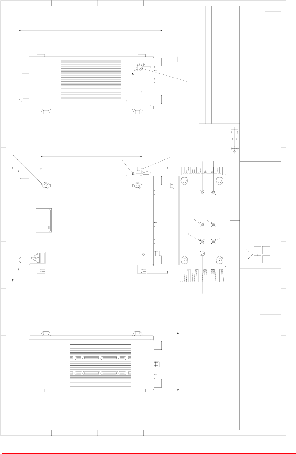
4.1.5 BDA Case Outline Drawing, Drg. Nō. 55-118691
BANDSELECT LINE AMPLIFIER, MISSION VALLEY
OUTLINE DRAWING
55-118591
AA
1:5
MRB 14/5/04
Cell Enhancer
A er i al Faci l i t i es
E ngl and
Li m i t ed
CE - / - N
Product ref :
Heavy
CAUTION
470.00
537.00
281.00
500.00
ALARM
12v DC INPUT
WALL MOUNTING BRACKETS FOR M8 FIXINGS.
BYDAT EDESCRIPTIONNo
ISSUE
THIRD ANGL E PROJECTION
1 234 5678 9
A
B
C
D
E
F
1 234 5678 9
A
B
C
D
E
F
Fax : 01494 777002
Tel : 01494 777000
Aerial Facilities Limited
THIS IS A PRO PRIETARY DESIGN O F AERIAL FACILITIES LTD.
REPRODUCTION OR USE OF THIS DESIGN BY OTHERS IS
PERMISSIBLE O NLY IF EXPRESSL Y AUTHORISED IN WRITING
BY AERIAL FACILITIES LTD.
NO DECIM AL PL ACE ± 1 mm
O NE DECIM A L PL ACE ± 0 .3 mm
TWO DECIMAL PLACES ± 0.1mm
AL L DIM ENSIO NS ARE IN mm
UNLESS O THERWISE STATED
CHKD
DRAWN
APPD
DATE
T O L ERA NCES SCAL E
England
CUS TO M ER DRA WING .No
TITL E
3
A
2x LOCKABLE CATCHES
EARTH STUD
HEAVY DUTY RUBBER F00T
709.00
499.00
PART No : 55-118501
DOWNLINK INPUT
MATERIAL : CASE : ALUMINIUM ALLOY 5251-H2
FIXING BRACKETS : MILD STEEL
FINISH : PAINTED GREY RAL 7035
ENVIRONMENTAL CLASSIFICATION : IP65
GD RB
PROTOTYPE ISSUE
14/5/04
MRB
DOWNLINK O/P A
UPLINK OUTPUT
UPLINK I/P A
DOWNLINK O/P B
UPLINK I/P B
BA ECN3392
21/7/04
MRB

Mission Valley Radio Repeater Equipment + Upgrade
User/Maintenance Handbook
Handbook No. 50-078021HBKM Page 53 of 85
4.1.6 BDA Assembly (50-078017) Parts List
AFL Part # Part Description Qty.
02-007201 900MHz 8POLE 10-20MHz B/W SMA 4
07-004101 70-100MHz 3dB SPLITTER/COMBINER 2
07-005705 CROSSBAND CPLR XC 250/380 SMA 4
10-000701 1/4W0-30dB SWITCHED ATTENUATOR 2
11-005902 900MHz LOW NOISE AMP WITH RELAY ASS 2
12-018002 PA 800-960MHz 20W CLASS A 1
12-018601 POWER AMPLIFIER 900MHz 5W 1
17-000126 CELL ENHANCER LABEL 6 DIGIT 1
17-000526 CE 10/20W HEATSINK THERMAL GASKET 2
17-001109 CE AGC UNIT LOG DET/AMP ASSY (12v) 2
17-001201 C/E AGC UNIT ATTENUATOR ASSY 2
17-009020 ENCLOSURE 620 x 420 x 250 (3 H/S) ALU 1
20-001601 12V RELAY BOARD 1
80-031820 20W PA HEATSINK (NEEDS 17-000526) 1
80-032320 10W PA HEATSINK (NEEDS 17-000526) 1
91-030002 N ADAPTOR PANEL FEMALE:FEMALE 4
91-500011 PWR 3POLE PNL PLUG SEALED IP68 1
91-500015 PWR CON CAP SEALED with INT. THREAD 2
91-500016 PWR 6POLE PNL PLUG SEALED IP68 1
91-510032 20A SOCKET CONTACT PIN 4
91-600007 'D' 9 WAY BLACK SHELL 4
91-600014 'D' 9 WAY SOCKET S/B (NON FILTERED) 4
91-660001 2W5 MIXED D TYPE SOCKET (7 WAY) 2
96-700034 LED RED 5mm IP67 INTEGRAL RES 1
96-700035 LED GREEN 5mm IP67 INTEGRAL RES 1
97-400010 BLACK PLASTIC HANDLE 50mm HIGH 2
97-900003 RUBBER FOOT 1 1:2' DIA. 4
Mission Valley Radio Repeater Equipment + Upgrade
User/Maintenance Handbook
Handbook No. 50-078021HBKM Page 54 of 85
5. MASTER SITE UPGRADE
5.1 Master Site Upgrade Rack Assembly (50-078021)
5.1.1 Master Site Upgrade Rack Description
This upgrade to the Mission Valley radio repeater system is concerned only with the 800MHz band of
frequencies, which, in the original specification could carry up to 24 channels of cell data
simultaneously. The added hardware for this upgrade will increase the number of available channels
from 24 to 43 but the number of 19” racks remains at three (the original 40W amplifier shelves will not
now be needed and three new channel module shelves will be added).
The cellular amplifier is in addition to the 24 channels already in existence, the increase (19 channels,
6 x 8ch. sub-racks) is designed to alleviate radio congestion to the local BTS and to extend the
number of possible simultaneous uses. Because of the increased channel density, a pair of 80-
100Watt power amplifier shelves (50-146703), instead of the original 40Watt pair, are the main source
of downlink RF power in the system to maintain the effective power/channel. Only the downlink path is
channelised, the uplink path is band-selective and its traffic is limited only by the total carrier power
available.
All shelves have active device alarms and these are configured as a volt-free, relay contact pair
summary per shelf, terminating in the 9-way ‘D’ connector on the rear panel, pins 1 & 2.
The VHF system needs no upgrade at this time, so the VHF hardware remains the same.
5.1.2 Master Site Upgrade Rack Electrical Specification
PARAMETER SPECIFICATION
855-869MHz (Downlink)
Frequency ranges: 810-824MHz (Uplink)
VSWR: better than 1.5:1
DC power supply: +24V
Power consumption: 600Watts
AC power input: 230V AC (nominal)
1 All amplifier shelves
Alarms Fitted:
(summary volt-free contacts) 2 PSU shelf
5.1.3 Master Site Upgrade Rack Mechanical Specification
PARAMETER SPECIFICATION
Height: 40U Swingframe cabinet (x1)
Width: 600mm
Rack
Depth: 600mm
operational: -20°C to +60°C Temperature
range storage: -40°C to +70°C
Weight: >100kg
Humidity: 5 – 95% non-condensing
RF connectors: N type female
Environmental protection: IP44
Supply cable:
Unit supplied with suitable supply input
leads, connector and specified length of
cable

Mission Valley Radio Repeater Equipment + Upgrade
User/Maintenance Handbook
Handbook No. 50-078021HBKM Page 55 of 85
5.1.6 Master Site Upgrade Rack Assembly (50-078021) Parts List
AFL Part # Part Description Qty.
12-018002 PA 800-960MHz 20W CLASS A 2
17-009127 CHAN MOD 810-860MHz 30KHz 8p TCXO 19
50-078005 800MHz 80W HPA INTERFACE 1
50-078023 CHANNEL SHELF UPGRADE MISSIONVALLEY 6
50-146511 CHANNEL MODULE PSU 1
50-146703 800MHz CHN SELECT POWER AMPLIFIER 2
50-146704 800MHz CHANNEL SELECTIVE PSU 2
60-020608 40U SWING FRAME CABINET 1
97-500167 RITTAL TS EARTHQUAKE KIT 1
97-500168 RITTAL TS BASE/PLINTH SEISMIC 4 1
99-000082 PALLET 900 x 900 x 7ply FOR RACKS 1
5.1.6a Upgrade Channel Module Shelf/Sub-Rack 50-078023 Parts List
AFL Part # Part Description Qty.
05-002602 900MHz SPLITTER/COMBINER, 20W 2
05-003302 4 WAY SPLITTER GSM 900MHz 4
17-002101 CHANNEL CONTROL MODULE 2
17-002103 26WAY RIBBON CABLE LEAD 8
17-003022 MODULE PATTERNED LEAVE 8
17-003023 SUBRACK SIDE PANEL 2
17-003024 SUBRACK REAR BRACKET 2
17-003025 BOTTOM MODULE GUIDE 8
17-003028 MODULE SQUARE LEAVE 8
17-003029 TOP MODULE GUIDE 8
91-130005 SMA BULKHEAD ADAPTOR F/F 2
91-500001 POWER PLG 3 PIN PNL.MOUNT NC-X 1
91-510003 3 PIN R.ANGLE FREE SOC.NC-X. 1
91-600007 'D' 9 WAY BLACK SHELL 2
91-600014 'D' 9 WAY SOCKET S/B (NON FILTERED) 1
91-600015 'D' 9 WAY PLUG S/B (NON FILTERED) 1
92-280033 Captive Screw 16
96-100001 20 x 5mm,10A FUSE HOLDER/CARRIER 1
96-110012 T 10A A.SURGE FUSE 20mm 1
97-000002 BLACK MODULE CAGE RUNNER 16
97-600001 SUBRACK FRONT HORIZ 2
97-600002 SUBRACK M2.5 STD TAP 42
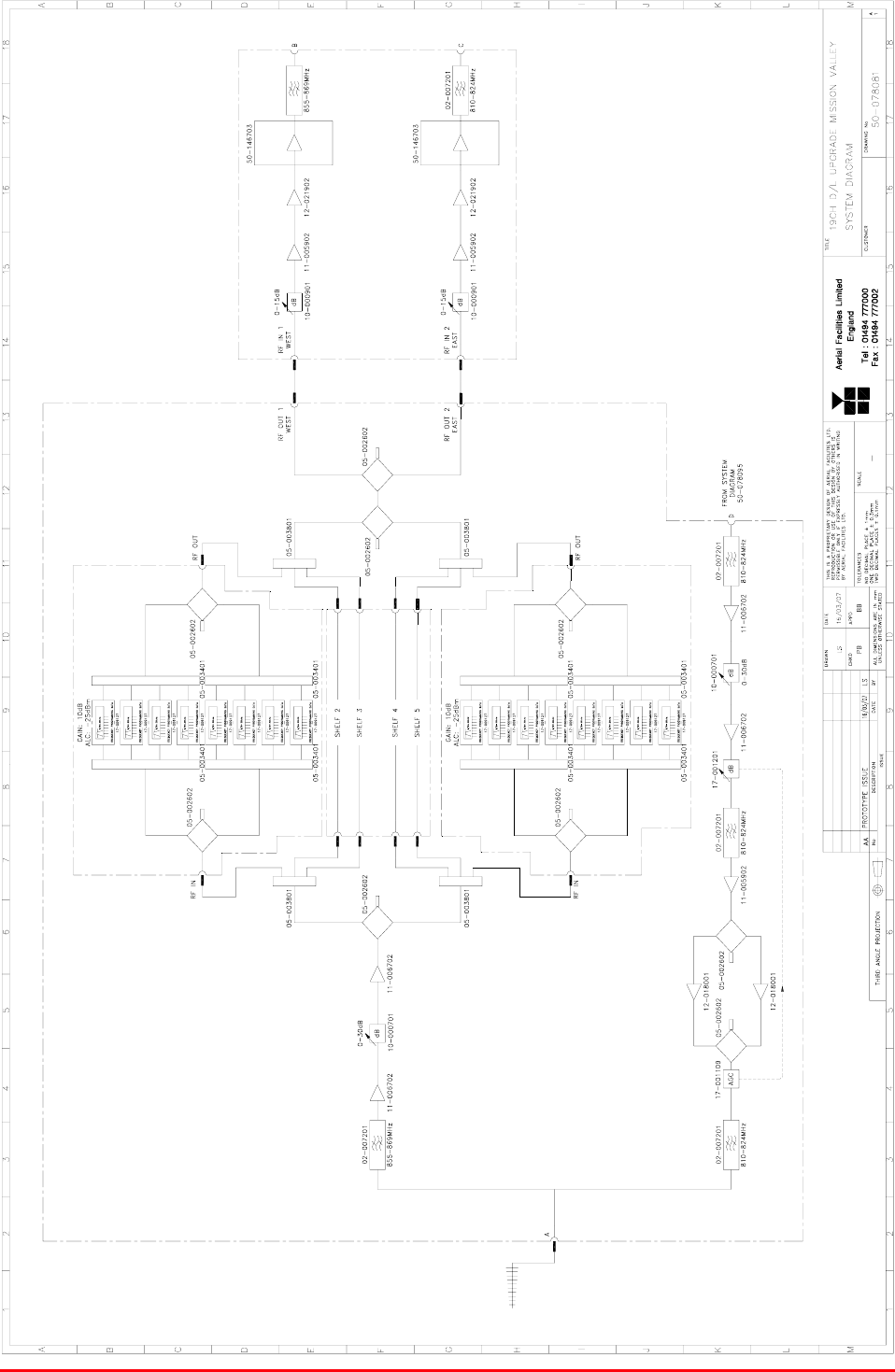
Mission Valley Radio Repeater Equipment + Upgrade
User/Maintenance Handbook
Handbook No. 50-078021HBKM Page 56 of 85
5.1.7 Master Site Upgrade System Diagram, Drg. # 50-078081

Mission Valley Radio Repeater Equipment + Upgrade
User/Maintenance Handbook
Handbook No. 50-078021HBKM Page 57 of 85
5.2 Upgrade Channel Frequencies
Chan # Tx Frequency Rx Frequency Type Modulation
1 868.4125 823.4125 C.C. Analog
2 868.1375 823.1375 C.C. Analog
3 868.0750 823.0750 Voice Analog
4 867.9125 822.9125 Voice Analog
5 867.6375 822.6375 Voice Analog
6 867.6125 822.6125 Voice Analog
7 867.4125 822.4125 Voice Analog
8 867.3875 822.3875 Voice Analog
9 867.1375 822.1375 Voice Analog
10 866.9125 821.9125 Voice Analog
11 866.8875 821.8875 Voice Analog
12 866.6375 821.6375 Voice Analog
13 866.4125 821.4125 Voice Analog
14 866.1375 821.1375 Voice Analog
15 866.0375 821.0375 BSI Analog
16 868.6000 823.6000 Voice Analog
17 867.0625 822.0625 Voice Analog
18 866.4375 821.4375 Voice Analog
19 868.4375 823.4375 Voice Analog
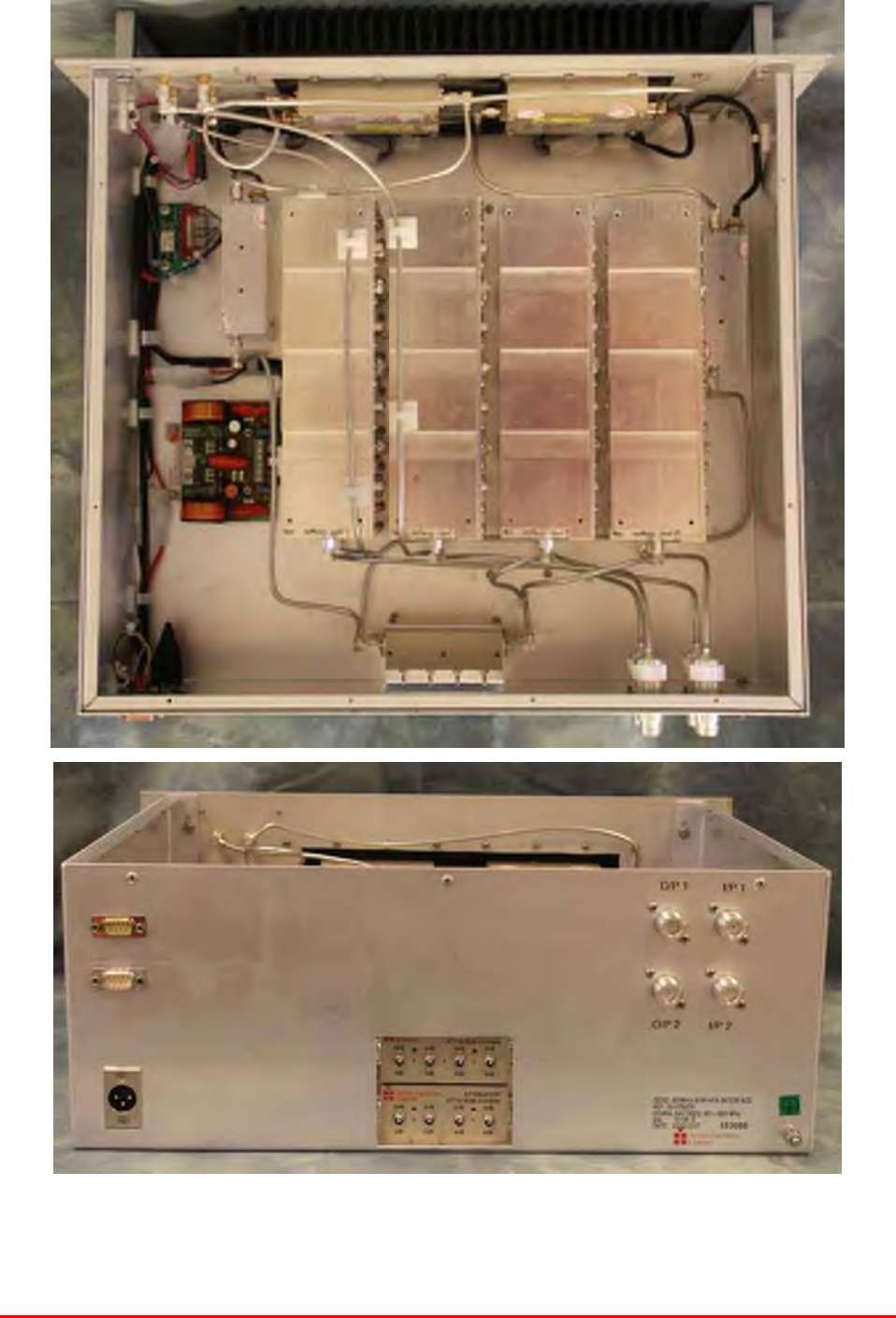
Mission Valley Radio Repeater Equipment + Upgrade
User/Maintenance Handbook
Handbook No. 50-078021HBKM Page 58 of 85
5.3 Master Site HPA Interface Shelf (50-078005)
5.3.P HPA Interface Shelf Photographs
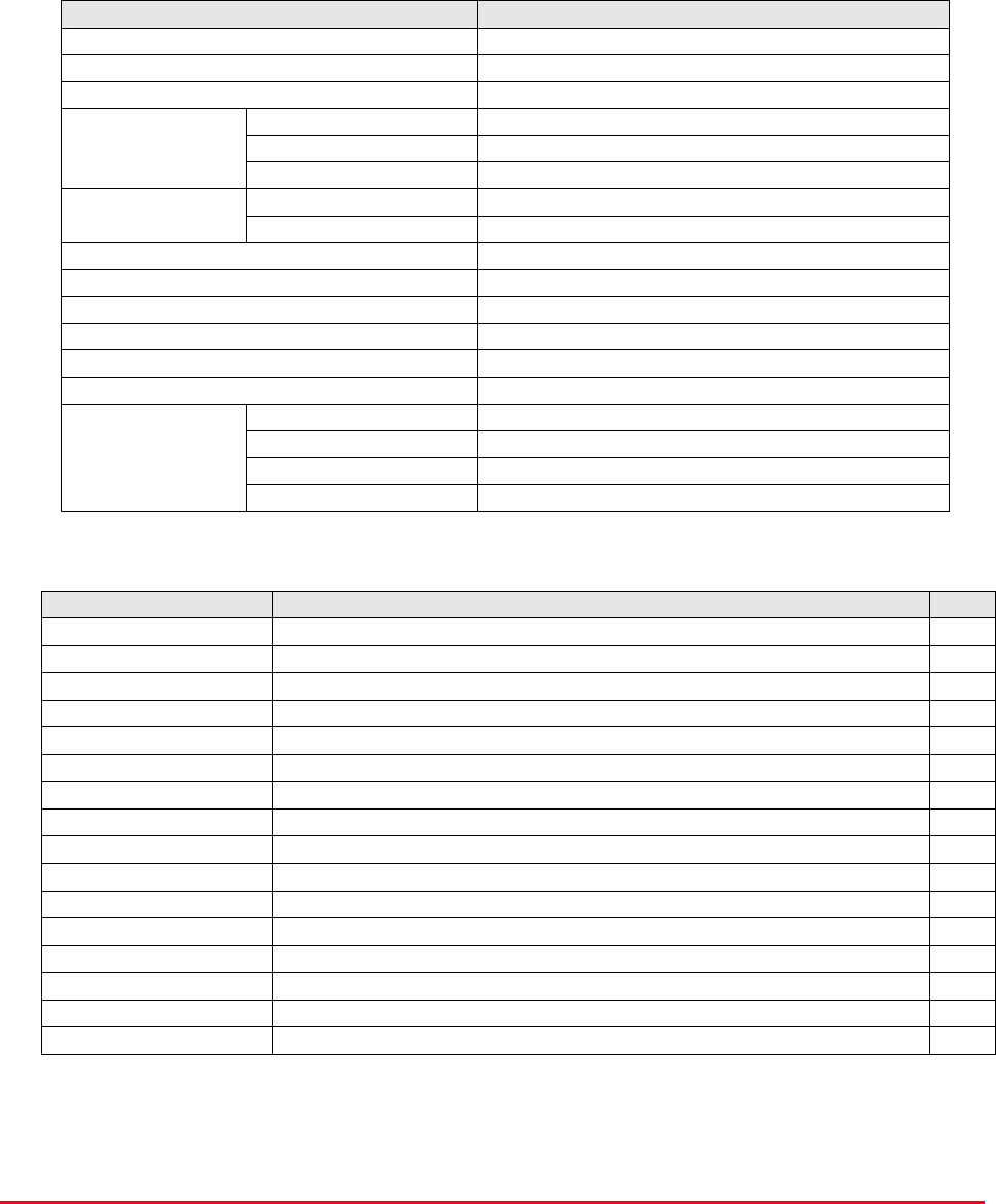
Mission Valley Radio Repeater Equipment + Upgrade
User/Maintenance Handbook
Handbook No. 50-078021HBKM Page 59 of 85
5.3.1 Description
These new high power (80Watts) amplifier shelves have been introduced in place of the 40W
amplifiers originally supplied. The higher power amplifiers are needed to maintain sufficient power per
channel for the 800MHz cellular repeater as there are now 19 extra channels. This shelf has two
amplifiers, a low noise amplifier and a low power (2W) amplifier which acts as a driver for the high
power shelf (50-146703). A 0-15dB switched attenuator at each of the two inputs allows accurate
balancing of the signal through the high power stages. As with all other shelves, alarms exist for all
the amplifiers and they terminate on the rear panel ‘D’ connector as a summary, volt-free relay
contact pair, pins 1 & 2.
5.3.2 Technical Specification
PARAMETER SPECIFICATION
Frequency range: 855-869MHz (Downlink)
Downlink output power: 2W (driver for HPA)
Uplink output power: N/A
Height: 3U
Width: 19" (482.6mm)
Shelf
dimensions Depth: <450mm (excluding connectors & handles)
operational: -20°C to +60°C Temperature
range storage: -40°C to +70°C
Weight: <15kg
Shelf gain: 50dB (typical)
Impedance: 50
Humidity: 5 – 95% non-condensing
RF Connectors: N type female
Environmental protection: IP44
Case: Alocrom 1200/Iridite NCP coating
Heatsinks: Black anodised aluminium
Handles: Silver anodised aluminium alloy
Finish
Fascia: Painted to RAL7035
5.3.3 Parts List
AFL Part # Part Description Qty.
02-007201 900MHz 8POLE 10-20MHz B/W SMA 4
10-000901 SW. ATTENUATOR 0.25W 0-15dB 2
11-005902 900MHz LOW NOISE AMP WITH RELAY ASS 2
12-005920 3U 10W PWR AMP HEATSINK 1
12-021902 POWER AMPLIFIER 900MHz 2W +12V 2
13-001803 DUAL DC/DC CONVERTER 24V-12V 1A 1
19-000921KL 3U chassis kit 400 deep with led 1
80-008901 12V RELAY PCB ASSEMBLY **NO LED** 1
91-030002 N ADAPTOR PANEL FEMALE:FEMALE 4
91-130005 SMA BULKHEAD ADAPTOR F/F 4
91-500001 POWER PLG 3 PIN PNL.MOUNT NC-X 2
91-510003 3 PIN R.ANGLE FREE SOC.NC-X. 2
91-600007 'D' 9 WAY BLACK SHELL 1
91-600014 'D' 9 WAY SOCKET S/B (NON FILTERED) 4
91-600015 'D' 9 WAY PLUG S/B (NON FILTERED) 1
94-100004 STPS12045TV 60A DUAL DIODE 1
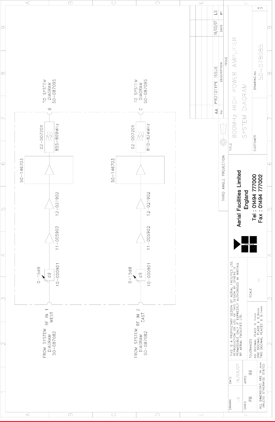
Mission Valley Radio Repeater Equipment + Upgrade
User/Maintenance Handbook
Handbook No. 50-078021HBKM Page 60 of 85
5.3.4 HPA Interface Shelf System Diagram, Drg. # 50-078085
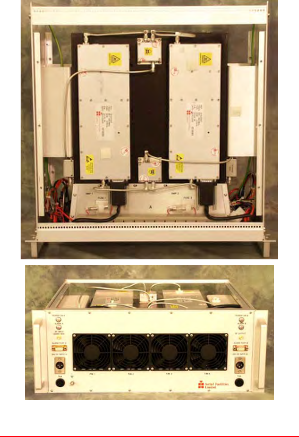
Mission Valley Radio Repeater Equipment + Upgrade
User/Maintenance Handbook
Handbook No. 50-078021HBKM Page 61 of 85
5.4 High Power Amplifier Shelf (50-146703)
5.4.P High Power Amplifier Shelf Photographs
Mission Valley Radio Repeater Equipment + Upgrade
User/Maintenance Handbook
Handbook No. 50-078021HBKM Page 62 of 85
5.4.1 Description
This amplifier is a Class A, fan cooled, 80W power amplifier in the frequency range 851 to 866MHz,
built into a 4U standard rack space unit. The fan-cooled amplifier is provided with an improving
linearity pre-distortion type correction circuit to give improved Output Intermodulation Intercept Point
(OIP3) and is housed in an aluminium case having an Iridite NCP finish. SMA connectors are used for
the RF input and output ports.
The amplifier has a 2 x NC-X connectors for the power supply and a Current Fault Alarm Function via
2 x 9-way D connectors (pins 1 & 2/amplifier). The unit operates from a 24V –Ve ground power
supply.
5.4.2 Electrical Specifications
PARAMETER SPECIFICATION
Frequency range: 851-866MHz
Bandwidth: <30MHz
Gain: 36dB (typical)
Gain Flatness: <0.5dB
1dB Compression Point: +49dBm (typical)
3rd order intercept: +69dBm (typical)
Input/Output return loss: >15dB
Connectors: SMA female
Supply: 18A @ 24V DC
Weight: 8kg
Size: 4U 19” Rack Mount 460mm Depth
Alarms: 2 x 9-way ‘D’ connectors, pins 1 & 2
operation: -20°C to +60°C Temperature
range: storage: -40°C to +70°C

Mission Valley Radio Repeater Equipment + Upgrade
User/Maintenance Handbook
Handbook No. 50-078021HBKM Page 63 of 85
5.4.3 Parts List
AFL Part # Part Description Qty.
05-002602 900MHz SPLITTER/COMBINER, 20W 6
05-002622 SPLITTER/COMBINER AUX. MTG PLATE 6
12-023301 PA 851-866MHz 20W LINEARIZED +24V 4
80-008902 24V RELAY PCB ASSEMBLY **NO LED** 2
80-245121 CLASS A LINEARIZED HEATSINK 2
80-245122 100WTETRA LINEARIZED H'SINK MTG BKT 2
80-245123 100WTETRA LINEARIZED SIDE PANEL 2
80-245124 100WTETRA LINEARIZED RACK LID 2
80-245125 100WTETRA LINEARIZED FRONT PANEL 1
80-245126 100WTETRA LINEARIZED DUCT END PLATE 2
80-245128 100WTETRA LINEARIZED DUCT MTG BLOCK 4
80-245129 100WTETRA LINEARIZED LID MTG BKT 4
80-245130 100WTETRA LINEARIZED DUCT TOP COVER 1
80-245131 100WTETRA LINEARIZED DUCT BOT COVER 1
80-245132 CLASS A LINEARIZED AMP CABLE TIDY 2
90-010021 RF CABLE SUPFLEX SMA R/A MALE 100mm 4
90-010024 RF CABLE SUPFLEX SMA R/A MALE 400mm 2
90-010026 RF CABLE SUPFLEX SMA R/A MALE 150mm 6
90-010027 RF CABLE SUPFLEX SMA R/A MALE 250mm 2
91-130005 SMA BULKHEAD ADAPTOR F/F 2
91-500001 POWER PLG 3 PIN PNL.MOUNT NC-X 2
91-600015 'D' 9 WAY PLUG S/B (NON FILTERED) 2
91-600019 'D'15 WAY SHELL (2W7) 4
91-640004 LARGE PIN FOR 91-660001 D SOCKET 8
91-660001 2W5 MIXED D TYPE SOCKET (7 WAY) 4
91-700017 ICD 15 WAY 0.1' CONNECTOR 2
91-700036 MISC 3 WAY PLUG HOUSING 4
91-700037 MISC 4 WAY PLUG HOUSING 2
91-700038 MISC PLG PIN FOR 3WAY HOUSING 14AWG 32
91-700039 MISC 3 WAY SOCKET HOUSING 6
91-700040 MISC 4 WAY SOCKET HOUSING 2
91-700042 MISC SOC.PIN FOR 3WAY HOUSING 14AWG 12
96-100004 32mm 20A (16A max load) FUSE HOLDER 2
96-110005 315mA FUSE GLASS A/SURGE 20X5 4
96-110015 T 15A A/SURGE FUSE 1.25' 2
96-110040 BULGIN IN-LINE FUSEHOLDER 20mm 4
96-400002 80 X 80MM 24V DC FAN SUNON 4
96-400003 PLASTIC FINGER GUARD 80X80mm 4
96-600003 INSULATING BOOT D.C. 2
96-700034 LED RED 5mm IP67 INTEGRAL RES. 24V 2
96-700035 LED GREEN 5mm IP67 INTEGRAL RES 24V 2
97-400002 HANDLE TYPE H6803 4U.[ALLOY] 2
97-600004 19" SUBRACK REAR RAIL 2
97-600005 19" SUBRACK FRONT RAIL 2
97-600008 19" SUBRACK TAPPED STRIP 2
97-600016 19" 4U SUBRACK MOUNTING FLANGE 2

Mission Valley Radio Repeater Equipment + Upgrade
User/Maintenance Handbook
Handbook No. 50-078021HBKM Page 64 of 85
6. INSTALLATION
When this equipment is initially commissioned, please use the equipment set-up record sheet in
Appendix B. This will help both the installation personnel and AFL should these figures be needed for
future reference or diagnosis.
6.1 General Remarks
The equipment racks that these master site shelves will be fitted into must be located on a flat, level
surface that is made from a material suitable for bearing the weight of the rack assembly. If the
installer is in any doubt about the suitability of a site it is recommended that he consult with an
appropriately qualified Structural Engineer.
It is important in determining the location of the rack within the room that space is allowed for access
to the front and rear of the equipment. To enable maintenance to be carried out, the doors must be
able to fully open.
The location must be served with a duct to allow the entry of cables into the unit.
The mains power supply is connected to the terminal strip located on the bulkhead at the rear of the
equipment at floor level. It is recommended that the connection is made by a qualified electrician, who
must satisfy himself that the supply will be the correct voltage and of sufficient capacity.
All electrical and RF connection should be completed and checked prior to power being applied for
the first time.
6.2 RF Connections
Care must be taken to ensure that the correct connections are made with particular attention made to
the base station TX/RX ports.
In the event that the base transmitter is connected to the RX output of the rack, damage to the
equipment will be done if the base station transmitter is then keyed.
Ensure that connections are kept clean and are fully tightened.
6.3 Commissioning
Once all connections are made the equipment is ready for commissioning.
Using the system diagrams and the end-to-end test specification, the equipment should be tested to
ensure correct operation.
On initial power up the system alarm indicators on the front panels of the equipment should be
checked. A red LED illuminated indicates a fault in that particular tray that must be investigated before
proceeding with the commissioning. A green LED on each shelf illuminates, to indicate that the power
supply is connected to the shelf
In the event that any part of the system does not function correctly as expected, check all connections
to ensure that they are to the correct port, that the interconnecting cables are not faulty and that they
are tightened. The majority of commissioning difficulties arise from problems with the interconnecting
cables and connectors.

Mission Valley Radio Repeater Equipment + Upgrade
User/Maintenance Handbook
Handbook No. 50-078021HBKM Page 65 of 85
7. MAINTENANCE
7.1 Fault Finding
7.1.1 Quick Fault Checklist
All AFL equipment is individually tested to specification prior to despatch. Failure of this type of
equipment is not common. Experience has shown that a large number of fault conditions relating to
tunnel installations result from simple causes often occurring as result of transportation, unpacking
and installation. Below are listed some common problems which have resulted in poor performance or
an indicated non-functioning of the equipment.
Mains power not connected or not switched on.
External connectors not fitted or incorrectly fitted.
Internal connectors becoming loose due to transport vibration.
Wiring becoming detached as a result of heavy handling.
Input signals not present due to faults in the aerial and feeder system.
Base transmissions not present due to fault at the base station.
Modems fitted with incorrect software configuration.
Changes to channel frequencies and inhibiting channels.
Hand held radio equipment not set to repeater channels.
Hand held radio equipment not set to correct base station.
7.1.2 Fault Isolation
In the event that the performance of the system is suspect, a methodical and logical approach to the
problem will reveal the cause of the difficulty. The system consists of modules fitted in shelves within
an environmentally protected enclosure (rack).
Transmissions from the main base stations are passed though the system to the mobile radio
equipment; this could be a handheld radio or a transceiver in a vehicle. This path is referred to as the
downlink. The return signal path from the mobile radio equipment to the base station is referred to as
the uplink.
The first operation is to check the alarms of each of the active units and determine that the power
supplies to the equipment are connected and active.
This can be achieved remotely (via CEMS, the RS232 Coverage Enhancement Management System,
if fitted), or locally with the front panel LEDs. The green LED on the front panel should be illuminated,
while the red alarm indicator should be off. If an alarm is on, then that individual module must be
isolated and individually tested against the original test specification.
The individual amplifier or FO units within the shelf have a green LED showing through a hole in their
piggy-back alarm board, which is illuminated if the unit is working correctly. If a module is suspect,
check the DC power supply to the unit. If no other fault is apparent use a spectrum analyser to
measure the incoming signal level at the input and then after reconnecting the amplifier input,
measure the output level. Consult with the system diagram to determine the expected gain and
compare result.
In the event that there are no alarms on and all units appear to be functioning it will be necessary to
test the system in a systematic manner to confirm correct operation.

Mission Valley Radio Repeater Equipment + Upgrade
User/Maintenance Handbook
Handbook No. 50-078021HBKM Page 66 of 85
7.1.3 Downlink
Confirm that there is a signal at the expected frequency and strength from the base station. If this is
not present then the fault may lay outside the system. To confirm this, inject a downlink frequency
signal from a known source at the master site BTS input and check for output at the remote site
feeder output.
If a signal is not received at the output it will be necessary to follow the downlink path through the
system to find a point at which the signal is lost. The expected downlink output for the given input can
be found in the end-to-end test specification.
7.1.4 Uplink
Testing the uplink involves a similar procedure to the downlink except that the frequencies used are
those transmitted by the mobile equipment.
7.1.5 Checking service
Following the repair of any part of the system it is recommended that a full end-to-end test is carried
out in accordance with the test specification and that the coverage is checked by survey.
It is important to bear in mind that the system includes a radiating cable network and base stations
that may be faulty or may have been damaged.

Mission Valley Radio Repeater Equipment + Upgrade
User/Maintenance Handbook
Handbook No. 50-078021HBKM Page 67 of 85
7.1.6 Fault repair
Once a faulty component has been identified, a decision must be made on the appropriate course to
carry out a repair. A competent engineer can quickly remedy typical faults such as faulty connections
or cables. The exceptions to this are cable assemblies connecting bandpass filter assemblies that are
manufactured to critical lengths to maintain a 50-ohm system. Care should be taken when replacing
cables or connectors to ensure that items are of the correct specification. The repair of component
modules such as amplifiers and bandpass filters will not usually be possible in the field, as they
frequently require specialist knowledge and test equipment to ensure correct operation. It is
recommended that items of this type are replaced with a spare unit and the faulty unit returned to AFL
for repair.
7.1.7 Service Support
Advice and assistance with maintaining and servicing this system are available by contacting Aerial
Facilities Ltd.
NOTE
Individual modules are not intended to be repaired on site and attempts at repair will
invalidate active warranties. Company policy is that individual modules should be repaired
by replacement. Aerial Facilities Ltd maintains a high level of stock of most modules which
can usually be despatched at short notice to support this policy.
7.2 Tools & Test Equipment
The minimum tools and test equipment needed to successfully service this AFL product are as
follows:-
Spectrum analyser: 100kHz to 2GHz (Dynamic range = 90dB).
Signal Generator: 30MHz to 2GHz (-120dBm to 0dBm o/p level).
Attenuator: 20dB, 10W, DC-2GHz, (N male – N female).
Test Antenna: Yagi or dipole for operating frequency.
Digital multi-meter: Universal Volt-Ohm-Amp meter.
Test cable x 2: N male – N male, 2M long RG214.
Test cable x 2: SMA male – N male, 1m long RG223.
Hand tools: Philips #1&2 tip screwdriver.
3mm flat bladed screwdriver.
SMA spanner and torque setter.

Mission Valley Radio Repeater Equipment + Upgrade
User/Maintenance Handbook
Handbook No. 50-078021HBKM Page 68 of 85
7.3 Care of Modules
7.3.1 General Comments
Many of the active modules contain semiconductor devices utilising MOS technology, which can
be damaged by electrostatic discharge. Correct handling of such modules is mandatory to ensure
their long-term reliability.
To prevent damage to a module, it must be withdrawn/inserted with care. The module may have
connectors on its underside, which might not be visible to the service operative.
7.3.2 Module Removal (LNAs, general procedure):
The following general instructions should be followed to remove a module:
1 Remove power to the unit
2 Remove all visible connectors (RF, DC & alarm)
3 Release module retaining screws.
4 Slowly but firmly, pull the module straight out of its position. Take care not to twist/turn the
module during withdrawal. (When the module is loose, care may be needed, as there may be
concealed connections underneath).
7.3.3 Module Replacement (general):
1 Carefully align the module into its location then slowly push the module directly straight into its
position, taking care not to twist/turn it during insertion.
2 Reconnect all connectors, RF, alarm, power etc.,(concealed connectors may have to be
connected first).
3 Replace retaining screws (if any).
4 Double-check all connections before applying power.
7.3.4 Power Amplifiers
1) Remove power to the unit. (Switch off @ mains/battery, or remove DC in connector)
2) Remove alarm wires from alarm screw terminal block or disconnect multi-way alarm
connector.
3) Carefully disconnect the RF input and output coaxial connectors (usually SMA)
If alarm board removal is not required, go to step 5.
4) There is (usually) a plate attached to the alarm board which fixes it to the amplifier, remove its
retaining screws and the alarm board can be withdrawn from the amplifier in its entirety. On
certain types of amplifier the alarm board is not mounted on a dedicated mounting plate; in this
case it will have to firstly be removed by unscrewing it from the mounting pillars, in most
cases, the pillars will not have not have to be removed before lifting the amplifier.
5) If the amplifier to be removed has a heatsink attached, there may be several different ways it
can have been assembled. The most commonly used method, is screws through the front of
the heatsink to threaded screw holes (or nuts and bolts), into the amplifier within the main
case. If the heatsink is mounted on the rear of the main case (e.g., against a wall in the case
of wall mounted enclosures), then the fixing method for the heatsink will be from within the
case, (otherwise the enclosure would have to be removed from the wall in order to remove the
heatsink).
When the heatsink has been removed, the amplifier may be unscrewed from the main casing by its
four corner fixings and gently withdrawn.
Fitting a new power amplifier module will be the exact reverse of the above.
Note: Do not forget to apply fresh heatsink compound to the heatsink/main case joint and
also between the amplifier and the main case.

Mission Valley Radio Repeater Equipment + Upgrade
User/Maintenance Handbook
Handbook No. 50-078021HBKM Page 69 of 85
7.3.5 Low Power Amplifier Replacement
1 Disconnect the mains power supply and disconnect the 24V dc supply connector for the LPA.
2 Disconnect the RF input and output cables from the LPA.
3 Disconnect the alarm connector.
4 Remove the alarm monitoring wires from (D type connector) pins 9 and 10.
5 Remove the LPA module by removing the four retaining screws, replace with a new LPA
module and secure it with the screws.
6 Connect the RF cables to the LPA input and output connectors. Reconnect the wires to the
alarm board connector pins 9 and 10.
7 Reconnect the DC supply connector and turn the mains switch on.
Note: Tighten SMA connectors using only a dedicated SMA torque spanner. If SMA
connectors are over-tightened, irreparable damage will occur. . Do not use adjustable
pliers to loosen/tighten SMA connectors.
Also take care not to drop or knock the module as this can damage (or misalign in the case of
tuned passive modules) sensitive internal components. Always store the modules in an
environmentally friendly location
7.3.6 Module Transportation:
To maintain the operation, performance and reliability of any module it must be stored and
transported correctly. Any module not installed in a whole system must be kept in an anti-static bag or
container. These bags or containers are normally identified by being pink or black, and are often
marked with an ESD label. Any module sent back to AFL for investigation/repair must be so
protected. Please contact AFL’s quality department before returning a module.

Mission Valley Radio Repeater Equipment + Upgrade
User/Maintenance Handbook
Handbook No. 50-078021HBKM Page 70 of 85
APPENDIX A
A.1 Glossary of Terms used in this document
Repeater or
Cell Enhancer
A Radio Frequency amplifier which can simultaneously amplify and re-
broadcast Mobile Station and Base Transceiver Station signals.
Band Selective
Repeater
A
Cell Enhancer designed for operation on a range of channels within a
specified frequency band.
Channel Selective
Repeater
A Cell Enhancer, designed for operation on specified channel(s) within a
specified frequency band. Channel frequencies may be factory set or on-
site programmable.
AC Alternating Current
AGC Automatic Gain Control
BBU Battery Backup Unit
BTS Base Transceiver Station
CEMS Coverage Enhancement Management System
C/NR Carrier-to-Noise Ratio
DAB Digital Audio Broadcasting
DC Direct Current
Downlink (D/L) RF signals Tx from the BTS to the Master Site
FO Fibre Optic
GND Ground
ID Identification Number
LED Light Emitting Diode
LCX Coaxial Leaky Feeder
LNA Low Noise Amplifier
LPA Low Power Amplifier
MOU Master Optical Unit
MS Master Site
MST Mobile Station
MTBF Mean Time Between Failures
N/A Not Applicable
N/C No Connection
OFR On Frequency Repeater
OIP3 Output Third Order Intercept Point = RFout +(C/I)/2
PA Power Amplifier
RF Radio Frequency
RSA Receiver/Splitter Amplifier
Rx Receiver
S/N Serial Number
TTL Transistor-Transistor Logic, a common type of digital circuit.
Tx Transmitter
Uplink (U/L) RF signals transmitted from the MS to the BTS
VSWR Voltage Standing Wave Ratio
WDM Wave division multiplex
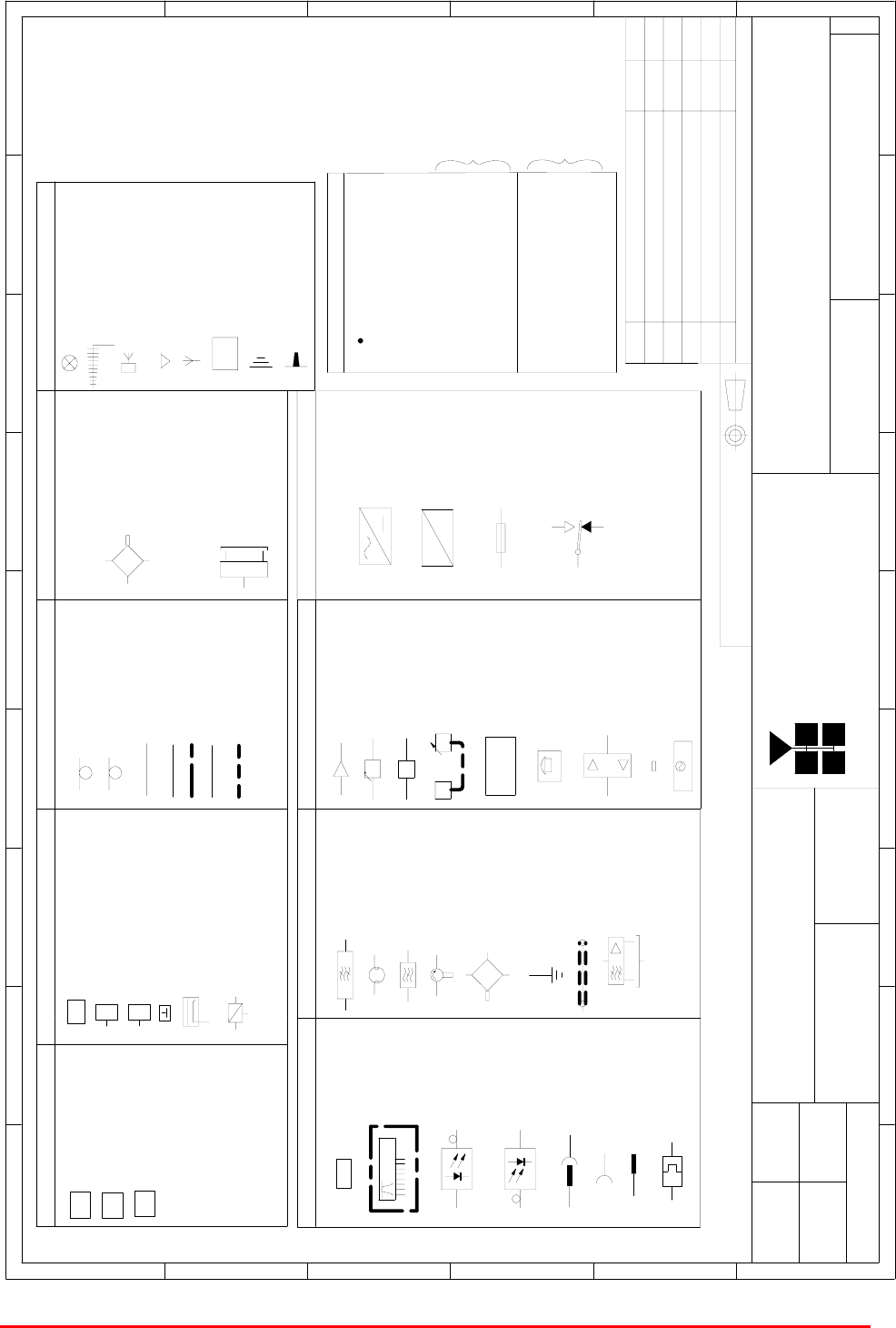
Mission Valley Radio Repeater Equipment + Upgrade
User/Maintenance Handbook
Handbook No. 50-078021HBKM Page 71 of 85
C0- AX CABLE
C0- AX CABLE
CAT 5 CABLE
CABLES
24/ FIBRE OPTIC CABLE/LINK
CABLE 1/ 2"
RADIATING CABLE
TAPPER/ COUPLER
STATION
BASE TRANSCEIVER
MISC
HUBS
FIBRE MAIN HUB
EXPANSION HUB
BI- DIRECTIONAL AMPLIFIER
E
BTS
FMH
EH
7/8 " DIA
1/2 " DIA
6 dB DIRECTIONAL COUPLER
10 dB COUPLER
C10
CROSS BAND COUPLER
COUPLERS
J JUMPER
C6
C10 10 dB DIRECTIONAL COUPLER
6 dB DIRECTIONAL COUPLER
DIRECTIONAL COUPLER
PANEL ANTENNA
( MOUNTED AT HIGH LEVEL)
DIRECTIONAL ANTENNA
FLAT PLATE ANTENNA
YAGI ANTENNA
ANTENNAS
REMOTE ANTENNA UNIT
OMNI ANTENNA
SPLITTERS
ANTENNA
RAU
BAND PASS FILTER
CAVITY RESONATOR
NOTCH FILTER
ISOLATOR
HYBRID COMBINER
EARTH STUD
LEEKY FEEDER
Outputs to receivers
R.S. A
AMPLIFIER
MISC
dB ATTENUATOR ( VARIABLE)
A. G.C
AGC dB
CONTROLLER
MONITORING
MODEM
MONITORING CONTROLLER
MODEM
( CELL ENHANCER)
FREQUENCY PROGRAMMING
DATA
B / W= 30 to 200 kHz CHANNEL MODULE
FIBRE- OPTIC
MODULATOR
FIBRE- OPTIC
DEMODULATOR
LOCAL OSCILLATOR
( up to
16 way)
Outputs
DUMMY LOAD
LOCAL OSCILLATOR
SPLITTER
MISC
8/ FIBRE OPTIC CABLE/LINK
STANDARD FOR LEVEL (dBm)
- 73 = BELOW ACCEPTABLE
SIGNAL LEVEL(dBm)
ALL AIRPORTS
BCCH ( BROADCAST
IDENTITY CODE)
BSIC ( BASIC SITE
LEVEL (dBm)
- 83 = BELOW ACCEPTABLE
SIGNAL LEVEL(dBm)
- 82 = ACCEPTABLE SIGNAL
- 72 = ACCEPTABLE SIGNAL
CONTROL CHANNEL)
= READING POSITION
22 =
602 =
SIGNAL KEY
STANDARD EXCEPT
FOR AIRPORTS
( SEE BELOW)
BLADE ANTENNA
ATTENUATOR ( FIXED)
dB
OUTIN
COUPLED
HI COM
LOW
HYBRID SPLITTER
IN
IN
OUT
OUT
IN
OUT
BYDATEDESCRIPTIONNo
ISSUE
THIRD ANGLE PROJECTION
1234 5 6 7 8 9
A
B
C
D
E
F
123456789
A
B
C
D
E
F
Fax : 01494 777002
Tel : 01494 777000
Aerial Facilities Limited
THIS IS A PROPRIETARY DESIGN OF AERIAL FACILITIES LTD.
REPRODUCTION OR USE OF THIS DESIGN BY OTHERS IS
PERMISSIBLE ONLY IF EXPRESSLY AUTHORISED IN WRITING
BY AERIAL FACILITIES LTD.
NO DECIMAL PLACE ± 1mm
ONE DECIMAL PLACE ± 0. 3 m m
TWO DECIMAL PLACES ± 0.1mm
ALL DIMENSIONS ARE IN mm
UNLESS OTHERWISE STATED
CHKD
DRAWN
APPD
DATE
TOLERANCES SCALE
England
CUSTOMER DRAWING.No
TITLE
3
A
AFL - STANDARD SYMBOLS
90- 000001
AA
NTS
PL 10/05/ 00
ORIGINAL
ISSUE
PL23/05/ 00
21/06/ 00 PLBLADE ANTENNA ADDED1A
2A ECN3165
RF
RF
PLUG & SOCKET
FIBRE OPTIC
CONNECTOR
FC/ APC
SOCKET
PLUG
MISC
DC
DC
AC TO DC PSU
DC TO DC
CONVERTER
FUSE
RELAY
N.O. ( CLEAR CONTACT)
N.C. ( FILLED CONTACT)
COM
MB GD
26/01/ 04 PL
2B TEXT CORRECTION 28/07/ 04 PL
A.2 Key to AFL RF Module Drawing Symbols

Mission Valley Radio Repeater Equipment + Upgrade
User/Maintenance Handbook
Handbook No. 50-078021HBKM Page 72 of 85
A.3 EC Declaration of Conformity
In accordance with BS EN ISO/IEC 17050-1&-2:2004
Aerial Facilities Limited
Aerial House
Asheridge Road
Chesham
Buckinghamshire HP5 2QD
United Kingdom
DECLARES, UNDER OUR SOLE RESPONSIBILITY THAT THE FOLLOWING PRODUCT:
PRODUCT PART NO[S] 50-078017 & 50-078021
PRODUCT DESCRIPTION Mission Valley Tunnel radio repeater equipment
IN ACCORDANCE WITH THE FOLLOWING DIRECTIVES:
1999/5/EC The Radio & Telecommunications Terminal Equipment Directive Annex V
and its amending directives
HAS BEEN DESIGNED AND MANUFACTURED TO THE FOLLOWING STANDARD[S] OR
OTHER NORMATIVE DOCUMENT[S]:
BS EN 60950 Information technology equipment.
Safety. General requirements
ETS EN 301 489-1 EMC standard for radio equipment and services.
Part 1. Common technical requirements
I hereby declare that the equipment named above has been designed to comply with the relevant
sections of the above referenced specifications. The unit complies with all essential requirements
of the Directives.
SIGNED
B S BARTON
TECHNICAL DIRECTOR DATE: 22/01/2007
Registered Office: Aerial House, Asheridge Road, Chesham, Buckinghamshire, HP5 2QD England Registered No. 4042808 (England)
www.aerialfacilities.com

Mission Valley Radio Repeater Equipment + Upgrade
User/Maintenance Handbook
Handbook No. 50-078021HBKM Page 73 of 85
A.4 Amendment List Record Sheet
Issue
No.
Date Incorporated
by
Page Nos.
Amended
Reason for new issue
A 04/01/06 CMH 1st Draft
1 31/07/06 CMH 1st Issue
2A CMH Incorporated all hardware into
one document
Document Ref: 50-078021HBKM

Mission Valley Radio Repeater Equipment + Upgrade
User/Maintenance Handbook
Handbook No. 50-078021HBKM Page 74 of 85
A.5. Waste Electrical and Electronic Equipment (WEEE) Notice
The Waste Electrical and Electronic Equipment (WEEE) Directive became law in
most EU countries during 2005. The directive applies to the disposal of waste
electrical and electronic equipment within the member states of the European
Union.
As part of the legislation, electrical and electronic equipment will feature the
crossed out wheeled bin symbol (see image at left) on the product or in the
documentation to show that these products must be disposed of in accordance
with the WEEE Directive.
In the European Union, this label indicates that this product should not be disposed of with domestic
or "ordinary" waste. It should be deposited at an appropriate facility to enable recovery and recycling.
Mission Valley Radio Repeater Equipment + Upgrade
User/Maintenance Handbook
Handbook No. 50-078021HBKM Page 75 of 85
APPENDIX B Initial Equipment Set-up Calculations
GENERAL INFORMATION
Site Name:
Client Name:
Date:
AFL Equip. Model No.
ANTENNA SYSTEMS
Model Gain Azimuth Comments
A - Service Antenna
B – Donor Antenna
Type Loss Length Comments
C – Service Feeder
D – Donor Feeder
INITIAL PARAMETERS
E – CE Output Power dBm
F – Antenna Isolation dB
G – Input signal level from donor BTS dBm
Operating Voltage V
DOWNLINK CALCULATIONS
Parameter Comments Value
Input signal level (G) dBm
CE max. o/p power (E) dBm
Gain setting E - G dB
ISOLATION REQUIRED Gain + 10dB dB
Service antenna gain (A) dB
SERVICE ANTENNA FEEDER LOSS (C) dB
EFFECTIVE RADIATED POWER (ERP) E+A-C dBm
Attenuator setting CE gain-gain setting dB
If the input signal level in the uplink path is known and steady, use the following calculation table to
determine the gain setting. If the CE features Automatic Gain Control the attenuator should be set to
zero and if not, then the attenuation setting for both uplink and downlink should be similar.
UPLINK CALCULATIONS
Parameter Comments Value
Input signal level dBm
CE max. o/p power (E) dBm
Gain setting dB
Required isolation dB
Donor antenna gain (B) dB
Donor antenna feeder loss (D) dB
Effective radiated power (ERP) E+B-D dBm
Attenuator setting (CE gain-gain setting) dB

Mission Valley Radio Repeater Equipment + UpgradeUser/Maintenance Handbook
APPENDIX C Battery Backup
Handbook No. 50-078021HBKM Page 76 of 85
APPENDIX C - BATTERY BACKUP
C.1 GENERAL DESCRIPTION
The 80-209302 Battery Backup Unit is designed to complement AFL’s extensive range of Cell
Enhancers and provide for continued operation during mains power failure.
The Battery Backup Unit is mounted in a single environmentally-protected case. NOTE:
Although battery back-up units are fitted in an IP65 case, they are open to the local
environment via coarsely filtered grill apertures which are necessary to allow the escape of
gasses from the batteries when they are being charged or discharged. Handles are provided
for carrying the unit and the door is fitted with locks. All the power and alarm connections are
via rugged IP68 sealed connectors.
The Battery Backup Unit contains a switch-mode power supply module (SMPSU), the batteries,
a battery charger and the associated control circuitry. In particular a low-voltage cut-off is fitted
to shut the system down after extended operation to prevent deep discharge of the batteries.
The Battery Backup Unit is fitted as standard with two alarms, a combined power supply and
charger alarm and an intruder alarm. The intruder alarm operates when the enclosure door is
opened. Both alarm circuits are volt-free contacts which are normally closed and become open
circuit in a fault condition. The Battery Backup Unit can be fitted with a more comprehensive
alarm and monitoring alarm system if required. In these cases the Battery Backup Unit can also
be fitted with alarms for AC failure, temperature, etc. and be interfaced for use with the Cell
Enhancer remote alarm reporting system.
When the Battery Backup Unit is used as the default power source for the Cell Enhancer, the
Cell Enhancer only requires a 12V DC supply input. This has the effect of removing the power
supply from the Cell Enhancer case, therefore saving on cost, weight and most importantly
reducing heat generation within the Cell Enhancer case.
The Battery Backup Unit is designed to provide typically four hours autonomy in the event of
mains supply failure. However, this will vary depending on the load presented by the Cell
Enhancer and the size of the batteries fitted.
The circuit diagram and schematic contained in this handbook are based on the standard
model. All Battery Backup Units are capable of being customised to individual customers
requirements for battery capacity, alarms etc. and the drawings may differ from those included
in this manual.
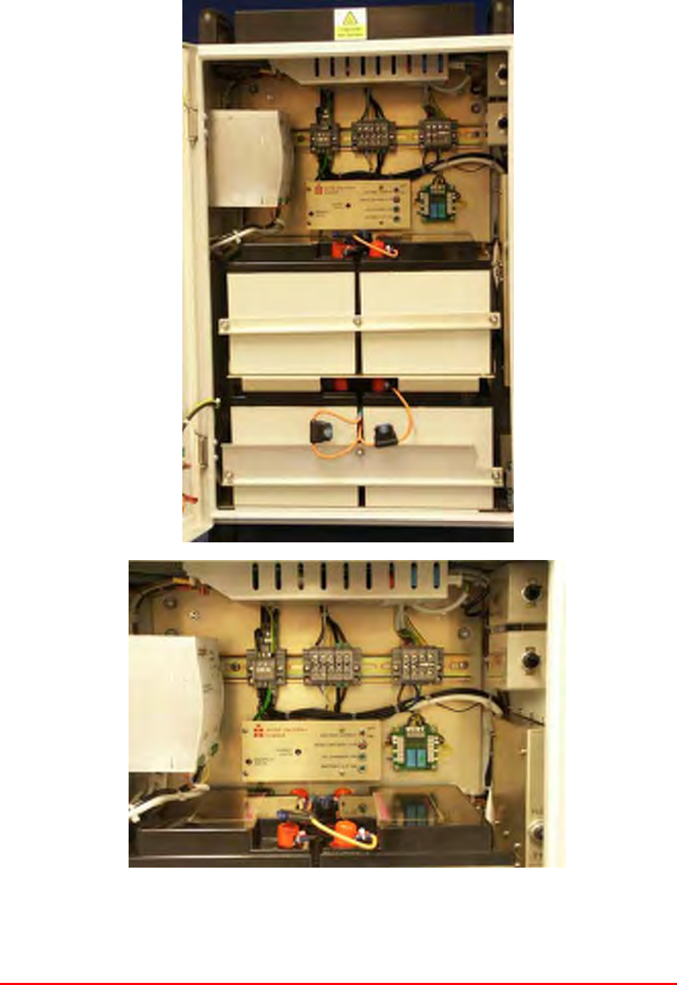
Mission Valley Radio Repeater Equipment + UpgradeUser/Maintenance Handbook
APPENDIX C Battery Backup
Handbook No. 50-078021HBKM Page 77 of 85
C.2. BATTERY BACKUP PHOTOGRAPHS
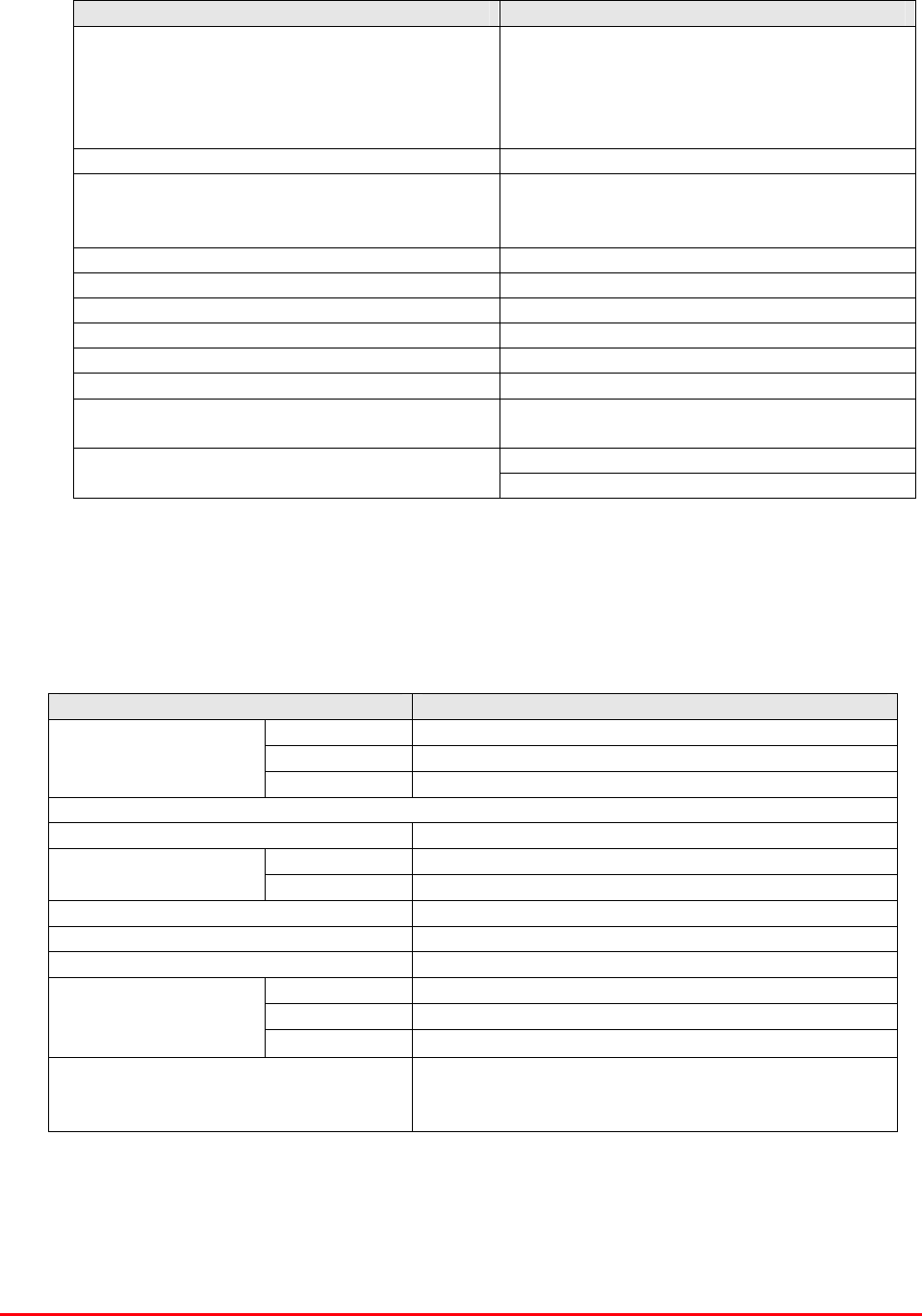
Mission Valley Radio Repeater Equipment + UpgradeUser/Maintenance Handbook
APPENDIX C Battery Backup
Handbook No. 50-078021HBKM Page 78 of 85
C.3. SPECIFICATION
C.3.1 Technical Specification
PARAMETER SPECIFICATION
Input Voltage:
Main SMPSU:-
90 Vac to 264 Vac Universal Input.
Battery Charger:-
93-132 Vac and 187-264 Vac
Switch selectable
Input Frequency: 47 to 63 H
Input Current: <2.0 A typical at 230 Vac (8.0A maximum
when charging batteries after extended
mains outage at 110 Vac)
Rating Of SMPSU: 27A at 30°C, 21A at 55°C.
Output (Load) Voltage: +12.5V DC
Output (Load) Current: 9A (typical)*
Battery Run Time: 8 hours (typical)*
Batteries: 4 x 12V, 40Amp/hour*
Low Voltage Cut-off Point: 10.5V
Standard Alarms: 1: Power supply alarms
2: Door open alarm
3: AC supply failure alarm
Optional Alarms Available: 4. Temperature alarm
* The load current will vary depending on the exact model of Cell Enhancer being driven
from the power supply. Although 9 Amps is a typical figure, models with higher power
amplifiers or more gain draw more current. This will be reflected in the battery run time.
C.3.2 Mechanical Specification
PARAMETER SPECIFICATION
Height: 620mm
Width: 420mm
Case size
Depth: 250mm
(excluding heatsinks, connectors, handles and feet)
Fixings: 4 holes on 470(w) x 500(h)mm
operational: -30°C to +55°C
Temperature
Range: storage: -40°C to +70°C
Weight: 75kg (approximately)
RF Connectors: N type female
Environmental Protection: IP65 (with door closed and all ports terminated)
Case: To RAL 7035
Heatsinks: Matt black (where fitted)
Finish:
Handles: Black Technopolymer
Supply Cable:
Unit supplied with suitable supply input leads with
connector and appropriate length of cable (where
appropriate)

Mission Valley Radio Repeater Equipment + UpgradeUser/Maintenance Handbook
APPENDIX C Battery Backup
Handbook No. 50-078021HBKM Page 79 of 85
C.3.3 Technical Description
AFL Cell Enhancer/repeater equipment often requires backup against failure of the mains AC supply.
Since the equipment runs on a 12V DC supply the most efficient method of providing backup is by a
bank of dry lead acid batteries of adequate capacity.
The Battery Backup Power Supply Unit incorporates a 400 Watt DC power supply and a
Charger/Regulator with a bank of two 12V 40AH batteries connected in parallel. The 400 Watt
SMPSU power supply will provide 12V DC to power the repeater under normal running conditions
from the mains supply. The batteries will provide 12V DC if the mains supply fails.
To reach maximum capacity the batteries need a charging voltage of 13.5V and this is provided by a
commercially available TRACO type TIS300-124 power supply with an output current capability of
10A maximum. The disadvantage with lead acid batteries is the high terminal voltage during charging.
AFL repeaters employ a diode combiner to sum the 12V DC output of the SMPSU DC power supply
and the battery bank DC output. The diode combiner is used to achieve "no break" changeover on
mains failure, however, if during charging the battery output has a greater voltage than the SMPSU
DC power supply the repeater will draw current from the batteries and not the SMPSU. A further
disadvantage is that the power dissipation in the repeater amplifiers is 30% greater with a 13.5V
supply and some power amplifier devices are rated to 14V maximum collector voltage leaving little
margin for safety.
To overcome these problems the Battery Backup Power Supply must regulate the battery voltage to
be slightly below that of the SMPSU. At the same time when the AC supply is off and the equipment is
running from batteries the voltage drop across the regulator must be a minimum to achieve maximum
backup time as the batteries discharge.
A further requirement is to prevent the effect known as "deep discharge" which shortens battery life.
This means the load must be disconnected from the batteries when they become discharged to a
terminal voltage of approximately 10.5V.
The charger power supply charges the 2 series connected batteries through blocking diodes. The
diodes prevent unwanted current flows between circuit elements. The battery charger DC output is
connected through the Battery Output ON/OFF switch to the Charger Control Board via a diode where
it powers the low voltage disconnect comparator. The comparator senses the battery voltage via a
potential divider and compares it to a fixed 5V reference. Adjustment of the potentiometer VR1 sets
the minimum battery voltage at which the low voltage disconnect relay remains energised and the
output to an 18V regulator is enabled.
In the absence of an AC input the supply to the comparator is maintained from the batteries via a
second diode through the contacts of the low voltage disconnect relay. When the comparator
releases the low voltage disconnect relay the comparator supply is interrupted. The low voltage
disconnect relay will then remain de-energised (Battery Output Off) until either the AC supply returns
or the Reset pushbutton is pressed. On actuation of the Reset pushbutton the output will be restored
provided the battery voltage exceeds the comparator threshold set by the potentiometer VR1.
Output from the low voltage disconnect relay is routed to the 9V regulator which provides a stabilised
9 Volt output determined by two divider resistors. This supply feeds a voltage doubler circuit
configured from a square wave multi-vibrator and two chopper field effect transistors. Two diodes
form the voltage doubling rectifier so that in normal operation approximately 33 Volts is available
across doubler circuit capacitors.
The 16 Volt supply is routed via the control element transistor to the gate of a Power MOSFET which
is the series pass element for regulating the 13.5V battery voltage to 12.5 Volts at the final output.
The FET is chosen for its ability to pass high currents (>30A) with a very low voltage drop (100mV).
To achieve this performance requires that the gate is at least 6V more positive than the drain &
source terminals. This is the reason for the Voltage doubler supply for driving the gate.
The output voltage is sensed by a second potential divider and compared with the reference voltage
from a zener diode to drive the control element transistor for the gate voltage of the pass element.
Adjustment of the second potentiometer VR2 sets the output voltage to the required value.
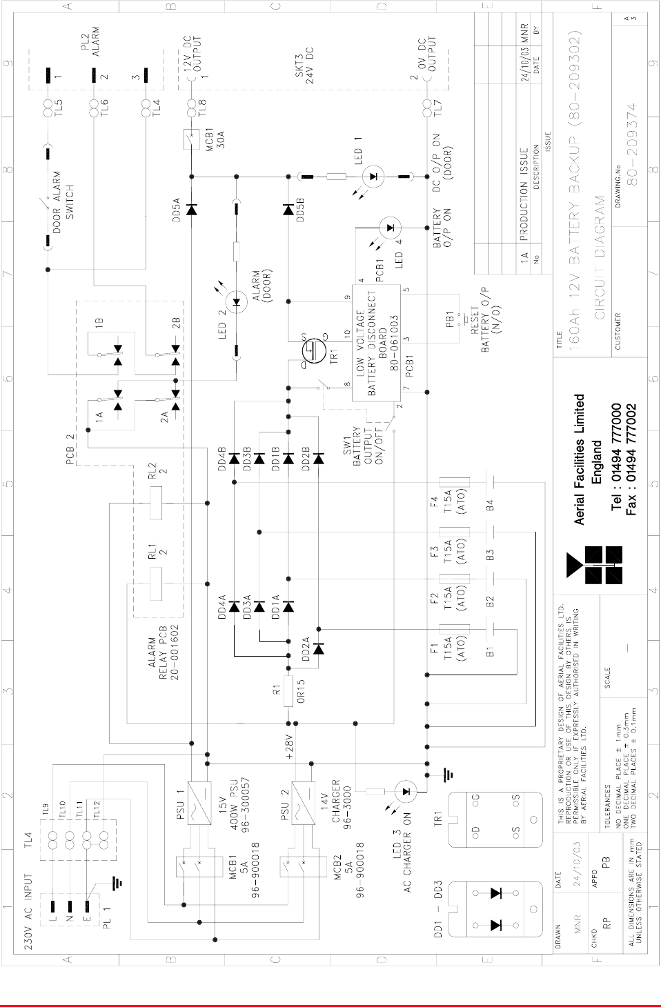
Mission Valley Radio Repeater Equipment + UpgradeUser/Maintenance Handbook
APPENDIX C Battery Backup
Handbook No. 50-078021HBKM Page 80 of 85
C.4. GENERAL DRAWINGS
C.4.1 Drg. No. 80-209374, 160Ah 12V Battery Backup Circuit Diagram
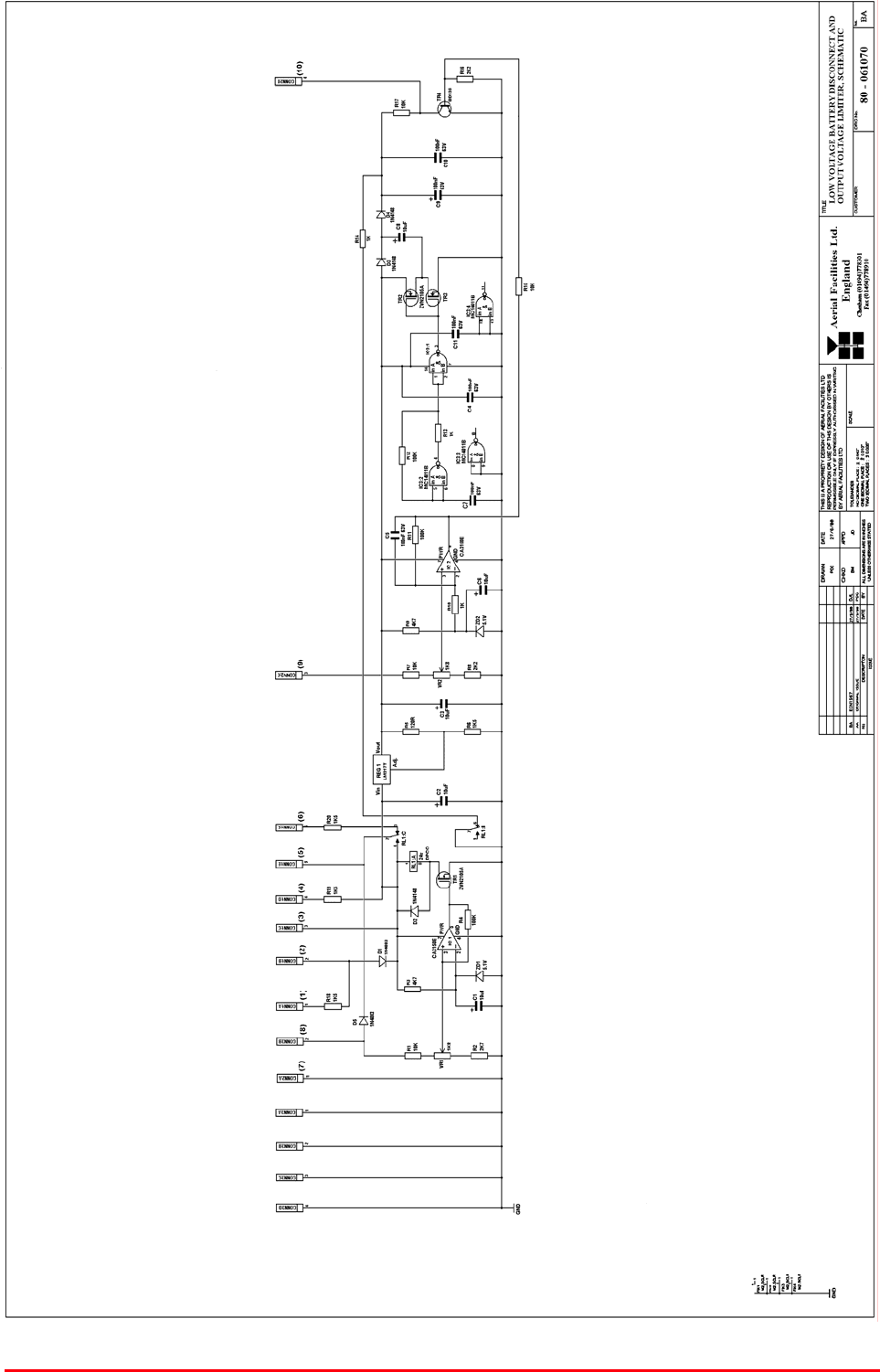
Mission Valley Radio Repeater Equipment + UpgradeUser/Maintenance Handbook
APPENDIX C Battery Backup
Handbook No. 50-078021HBKM Page 81 of 85
C.4.2 Low Voltage Battery Disconnect and O/P Voltage Limiter Schematic
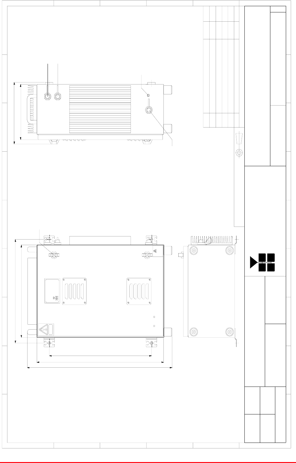
Mission Valley Radio Repeater Equipment + UpgradeUser/Maintenance Handbook
APPENDIX C Battery Backup
Handbook No. 50-078021HBKM Page 82 of 85
C.4.3 Battery Backup Case Outline Drawing
500620
709
420
470
250
Heavy
CAUTION
voltage
High
DANGER
2 LOCKABLE
DOOR CAT CHES
BYDATEDESCRIPT IONNo
THIRD ANGLE PROJECTION
1234 5 6 7 8 9
A
B
C
D
E
F
12345678
9
A
B
C
D
E
F
Fax : 01494 777002
Tel : 01494 777000
Aerial Facilities Limited
THIS IS A PROPRIETARY DESIGN OF AERIAL FACILITIES LTD.
REPRODUCTION OR USE OF THIS DESIGN BY OTHERS IS
PERMISSIBLE ONLY IF EXPRESSLY AUTHORISED IN WRITING
BY AERIAL FACILITIES LTD.
NO DECIMAL PLACE ± 1mm
ONE DECIMAL PLACE ± 0.3mm
TWO DECIMAL PLACES ± 0.1mm
ALL DIMENS IONS ARE IN mm
UNLESS OT HERWISE STATED
CHKD
DRAWN
APPD
DAT E
TOLERANCES SCALE
England
CUSTOMER DRAW ING.No
TITLE
ISSUE
3
A
40Ah BATTERY BACK UP
OUTLINE DRAWING
55-118591
1A
1:5
PB 14/05/04
PRODUCTION ISSUE
14/ 05/ 04
MNR
ENVIRONMENTAL CLASSIFICATION: I P65
MATERIAL: MILD STEEL ENCLOSURE
FI NI SH: RAL7035
ALARM
DC OUTPUT
AC INPUT
EARTH STUD
BATTERY
Aerial Facilities
Limited
En gla n d
BACK UP
280
PB CT
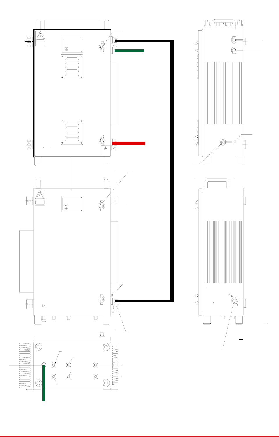
Mission Valley Radio Repeater Equipment + UpgradeUser/Maintenance Handbook
APPENDIX C Battery Backup
Handbook No. 50-078021HBKM Page 83 of 85
C.4.4 BBU/Amplifier Power Wiring And Alarms Diagram
Cell Enhancer
Aerial F acilities
England
Li m i t ed
CE- / - N
Produc t ref :
Heavy
CAUT ION
ALARM
24v DC I NPUT
WALL MOUNTING BRACKETS FOR M8 FI XINGS.
2x LOCKABLE CATCHES
EARTH STUD
HEAVY DUT Y RUBBER F 00T
DOWNLINK INPUT
DOWNLI NK O/ P A
UPLI NK OUT PUT
UPLINK I/P A
DOWNLI NK O/ P B
UPLINK I/P B
Heavy
CAUT ION
vol t age
High
DANGER
2 L OC KABLE
DOOR CATCHES
ALARM
DC OUTPUT
AC INPUT
EARTH STUD
BATT ER Y
Aerial Facili ties
Li m i t ed
England
BAC K U P
110V A.C
INPUT
ALARM(TO CONTROL ROOM)
PI N 1
PI N 2
12V OUT PIN 1=12V, PIN 2=0V
12V IN PIN 1=12V, PIN 2=0V
ALARMS(TO CONROL ROOM)
PI N 1
PI N 2

Mission Valley Radio Repeater Equipment + UpgradeUser/Maintenance Handbook
APPENDIX C Battery Backup
Handbook No. 50-078021HBKM Page 84 of 85
C.5. BBU ALARMS & MONITORING SYSTEM
C.5.1 Description
The Battery Backup is fitted with a two alarm outputs. The Summary Alarm (Pins 1 & 2) has
normally closed, volt free, contacts which open when either the SMPSU output fails and/or the
battery charger output fails and/or the door to the Battery Backup is opened.

Mission Valley Radio Repeater Equipment + UpgradeUser/Maintenance Handbook
APPENDIX C Battery Backup
Handbook No. 50-078021HBKM Page 85 of 85
C.6. INSTALLATION
C.6.1 Battery Backup Unit Installation
The procedure for installing and commissioning an AFL Cell Enhancer Battery Backup Unit is
generally as follows:
1 Fix the Battery Backup Unit in the chosen position.
2 Connect a suitable mains power supply to the Battery Backup Unit.
3 Connect the DC cable from the Battery Backup Unit to the Cell Enhancer.
4 Switch the Battery Backup Unit on by switching on the two circuit breakers and the
battery output switch on the internal indicator panel.
5 Test the Cell Enhancer to ensure correct operation from the Battery Backup Unit.
C.6.2 Power Supply Input Voltage Selection
The SMPSU module used within the AFL Cell Enhancer Battery Backup Unit is capable of
operation at any voltage between 90 Vac and 264 Vac. The battery charger power supply (Traco)
must be switched to either 115 or 230V nominal AC supplies. The supply changeover switch is
located on the top surface of the battery charger supply near to the front of the battery backup
case. This slide switch is recessed within the supply and can be operated by a small screwdriver.
C.7. MAINTENANCE
C.7.1 General Comments
The AFL Cell Enhancer Battery Backup Unit requires no routine maintenance. If a failure is
suspected it is possible with the aid of the block schematics (see section 3) to locate any
defective unit.
It should be borne in mind that a failure indicated by the alarm system could actually be a failure
in the alarm system! It is always worth checking that there really is a genuine problem by AC and
DC voltage measurements before starting to dismantle parts of the system. Lead-acid batteries
should be inspected every year for general condition the same way an auto battery would be
regarded.