PBE Europe as Axell Wireless 50-0780-800 800MHz Cell Enhancer User Manual
Axell Wireless 800MHz Cell Enhancer
Contents
- 1. User manual
- 2. Manual
User manual

800MHz & VHF Cell Enhancers
Maintenance Handbook
H/book Number:-50-078001HBKM Issue No:-A Date:-02/09/2004 Page:-1 of 88
24 Channel 800MHz
& VHF Cell Enhancers
Maintenance Handbook
For
Terry Consulting
AFL Works Order N.: Q111353
AFL product part N’s.: 50-078001 (800 & VHF CE’s)
80-209302 (Battery Back-up)

800MHz & VHF Cell Enhancers
Maintenance Handbook
H/book Number:-50-078001HBKM Issue No:-A Date:-02/09/2004 Page:-2 of 88
Table of Contents
AMENDMENT LIST RECORD SHEET .................................................................................................. 6
INTRODUCTION ....................................................................................................................................... 7
Scope...........................................................................................................................................................................7
Purpose.......................................................................................................................................................................7
Glossary of Terms .....................................................................................................................................................8
Key to AFL RF Module Drawing Symbols.............................................................................................................9
1. SAFETY CONSIDERATIONS ..................................................................................................... 10
1.1 Earthing of Equipment ..............................................................................................................................10
1.2 Electric Shock Hazard ...............................................................................................................................10
1.3 RF Radiation Hazard.................................................................................................................................11
1.4 Chemical Hazard........................................................................................................................................12
1.5 Emergency Contact Numbers ...................................................................................................................12
2. OVERVIEW/SYSTEM DESCRIPTION...................................................................................... 13
3. SPECIFICATION .......................................................................................................................... 14
3.P Photographs..................................................................................................................................................14
3.P.1 800MHz Air I/F Uplink Shelf 50-078002................................................................................................14
3.P.2 Eight Channel Downlink Shelf 50-078003 ..............................................................................................15
3.P.3 Power Amplifier/Driver Shelf 50-078004................................................................................................16
3.P.4 800MHz In-Line Amplifier 50-078017....................................................................................................17
3.P.5 VHF/800MHz Multi-Coupler Shelf 50-078015.......................................................................................18
3.P.6 VHF Simplex Shelf 50-078010................................................................................................................19
3.P.7 VHF Duplex Shelf 50-078011 .................................................................................................................20
3.P.8 VHF Air Interface Shelf 50-078012 ........................................................................................................21
3.P.9 VHF Combiner Shelf 50-078013 .............................................................................................................22
3.P.10 PSU Shelf 50-078014...........................................................................................................................23
3.P.11 Battery Backup 80-209302...................................................................................................................24
3.P.12 Rack Photos..........................................................................................................................................25
3.1 Electrical Specification ..............................................................................................................................29
3.2 Channel Frequency Listing .......................................................................................................................30
3.3 Mechanical Specifications..........................................................................................................................31
3.3.1 Rack Mounted Equipment Mechanical Specifications.............................................................................31
3.3.2 Wall Mounted Equipment (50-078017 & 80-209302).............................................................................31
3.4 Parts Lists ...................................................................................................................................................32
3.4.1 Whole System Parts List (50-078001) .....................................................................................................32
3.4.2 800MHz AIF Uplink Shelf 50-078002 Parts List ....................................................................................33
3.4.3 800MHz 8 Channel, Channel Module Shelf 50-078003 Parts List..........................................................34
3.4.4 800MHz 40W Amplifier Shelf 50-078004 Parts List ..............................................................................35
3.4.5 VHF Simplex Shelf 50-078010/1.............................................................................................................36
3.4.6 VHF Simplex Shelf 50-078010/2 Parts List.............................................................................................37
3.4.7 VHF Duplex Shelf 50-078011/1 Parts List ..............................................................................................38
3.4.8 VHF Duplex Shelf 50-078011/2 Parts List ..............................................................................................39
3.4.9 VHF Duplex Shelf 50-078011/3 Parts List ..............................................................................................40
3.4.10 VHF Duplex Shelf 50-078011/4 Parts List ..........................................................................................41
3.4.11 VHF Air Interface Shelf 50-078012 Parts List ....................................................................................42
3.4.12 VHF Combiner Shelf 50-078013 Parts List.........................................................................................42
3.4.13 VHF PSU Shelf 50-078014 Parts List..................................................................................................43
3.4.14 VHF/800MHz Tx Multi-coupler Shelf 50-078015 Parts List ..............................................................43
3.4.15 800Mhz In-Line Amplifier (Wall-Mount Case) 50-078017 Parts List ................................................44
3.4.16 12V 160Ahour Battery Back-Up 80-209302 Parts List .......................................................................45
4. SYSTEM DRAWINGS................................................................................................................... 47
4.1 24 Channel 800MHz & VHF Simplex/Duplex Cell Enhancers System Diagram.................................47
4.2 Generic Wall Mounted Cases Outline Drawing (50-078017 & 80-209302) ..........................................48

800MHz & VHF Cell Enhancers
Maintenance Handbook
H/book Number:-50-078001HBKM Issue No:-A Date:-02/09/2004 Page:-3 of 88
5. SUB-UNIT MODULES .................................................................................................................. 49
5.1 Bandpass Filters (02-007201 & 01-002503)..............................................................................................49
5.1.1 Description ...............................................................................................................................................49
5.1.2 Technical Specification (02-007201) .......................................................................................................49
5.1.3 Technical Specification (01-002503) .......................................................................................................49
5.2 900MHz Splitter/Combiner (05-002602)..................................................................................................50
5.2.1 Description ...............................................................................................................................................50
5.2.2 Technical Specification ............................................................................................................................50
5.3 1 Watt 3dB Broadband Splitter (05-002901) ...........................................................................................51
5.3.1 Description ...............................................................................................................................................51
5.3.2 Technical Specification ............................................................................................................................51
5.4 Four Way Splitter (05-003302) .................................................................................................................52
5.4.1 Description ...............................................................................................................................................52
5.4.2 Technical Specification ............................................................................................................................52
5.5 Four Way Hybrid Splitter (05-003401) ....................................................................................................52
5.5.1 Description ...............................................................................................................................................52
5.5.2 Technical Specification 05-003401..........................................................................................................52
5.6 3 Way Splitter/Combiner (05-003801) .....................................................................................................53
5.6.1 Description ...............................................................................................................................................53
5.6.2 Technical Specification ............................................................................................................................53
5.7 Wideband 3dB Splitter (07-004101) .........................................................................................................54
5.7.1 Description ...............................................................................................................................................54
5.7.2 Technical Specification ............................................................................................................................54
5.8 VHF/UHF 3-Way Splitter (07-005401).....................................................................................................55
5.8.1 Description ...............................................................................................................................................55
5.8.2 Technical Specification ............................................................................................................................55
5.9 3 Port Tx Hybrid Coupler (80-024203) ....................................................................................................56
5.9.1 Description ...............................................................................................................................................56
5.9.2 Technical Specification ............................................................................................................................56
5.10 Crossband Coupler (07-005705) ...............................................................................................................57
5.10.1 Description ...........................................................................................................................................57
5.10.2 Technical Specification ........................................................................................................................57
5.11 6dB Power Monitor (07-014002)...............................................................................................................58
5.11.1 Description ...........................................................................................................................................58
5.11.2 Technical Specification ........................................................................................................................58
5.12 2-Port RF Isolator (08-930002) .................................................................................................................59
5.12.1 Description ...........................................................................................................................................59
5.12.2 Technical Specification ........................................................................................................................59
5.13 ¼Watt 0- -30dB & 0-15dB Variable Attenuators (10-000701 & 10-000901) ........................................60
5.13.1 General Application .............................................................................................................................60
5.13.2 Switched Attenuators ...........................................................................................................................60
5.14 LNA’s (11-001202, 11-005802, 11-005902 11-006002, 11-006702 & 11-004802) ..................................61
5.14.1 Description ...........................................................................................................................................61
5.14.2 Technical Specification (11-001202) ...................................................................................................61
5.14.3 Technical Specification (11-004802) ...................................................................................................61
5.14.4 Technical Specification (11-005802) ...................................................................................................62
5.14.5 Technical Specification (11-005902) ...................................................................................................62
5.14.6 Technical Specification (11-006002) ...................................................................................................63
5.14.7 Technical Specification (11-006702) ...................................................................................................63
5.15 5, 10 & 20W 900MHz Power Amplifiers (12-018601, 12-018001 & 12-018002)...................................64
5.15.1 Description ...........................................................................................................................................64
5.15.2 Technical Specification (12-018601, 5W) ...........................................................................................64
5.15.3 Technical Specification (12-018001, 10W) .........................................................................................64
5.15.4 Technical Specification (12-018002, 20W) .........................................................................................65
5.16 VHF 5Watt Power Amplifier (12-004902) ...............................................................................................65
5.16.1 Description ...........................................................................................................................................65
5.16.2 Technical Specification ........................................................................................................................65

800MHz & VHF Cell Enhancers
Maintenance Handbook
H/book Number:-50-078001HBKM Issue No:-A Date:-02/09/2004 Page:-4 of 88
5.17 3 Stage Alarm PCB & 3 Stage Simplex Alarm PCB(12-002201 & 12-002203) ....................................66
5.17.1 Description ...........................................................................................................................................66
5.17.2 Technical Specification ........................................................................................................................67
5.17.3 Generic Summary Alarm Wiring Sketch .............................................................................................67
5.18 1 & 3 Stage Alarm/Simplex/Mute PCB (12-002804 & 12-002213) ........................................................68
5.18.1 Description ...........................................................................................................................................68
5.19 Simplex Controller PCB (12-002811) .......................................................................................................68
5.19.1 Description ...........................................................................................................................................68
5.20 Dual DC/DC Converter (13-001803) ........................................................................................................69
5.20.1 Description ...........................................................................................................................................69
5.20.1 Technical Specification ........................................................................................................................69
5.21 Simplex Squelch & AF Module (17-002802)............................................................................................70
5.21.1 Description ...........................................................................................................................................70
5.21.2 Technical Specification ........................................................................................................................70
5.22 Wide Dynamic Range (Log.) 12V AGC (17-001109, det. & 17-001201, atten.)....................................71
5.22.1 Description ...........................................................................................................................................71
5.22.2 Technical Specification ........................................................................................................................72
5.23 Channel Control Module (17-002101)......................................................................................................73
5.23.1 Description ...........................................................................................................................................73
5.23.2 Technical Specification ........................................................................................................................73
5.23.3 900MHz Programming Procedure........................................................................................................74
5.23.4 900MHz Programming Example..........................................................................................................75
5.24 Channel Selective Modules (17-009127 UHF, & 17-009135 VHF) ........................................................76
5.24.1 Description ...........................................................................................................................................76
5.24.2 Drg. N. 17-003080, Generic Channel Module Block Diagram..........................................................77
5.25 12 & 24V Relay Boards (20-001601 & 20-001602)..................................................................................78
5.25.1 Description ...........................................................................................................................................78
5.25.2 Technical Specification ........................................................................................................................78
5.26 12V Low Voltage Battery Disconnect Module (80-061003)....................................................................79
5.26.1 Description ...........................................................................................................................................79
5.26.2 Technical Specification ........................................................................................................................79
5.27 Crystal Filters (93-980109) ........................................................................................................................79
5.27.1 Description ...........................................................................................................................................79
5.28 IXFN170N10 Power Mos-Fet Module (94-030015).................................................................................79
5.28.1 Description ...........................................................................................................................................79
5.29 STPS12045TV 60A Dual Diode Assembly (94-100004) ..........................................................................80
5.29.1 Description ...........................................................................................................................................80
5.30 15V Switch-Mode PSU (96-300054)..........................................................................................................80
5.30.1 Description ...........................................................................................................................................80
5.30.2 Technical Specification ........................................................................................................................80
6. INSTALLATION............................................................................................................................ 81
6.1 Initial Installation Record .........................................................................................................................81
6.1.1 Rack Mounted Equipment........................................................................................................................81
6.1.2 Wall Mounted Equipment ........................................................................................................................81
6.1.3 Electrical Connections..............................................................................................................................81
6.1.4 RF Connections........................................................................................................................................82
6.2 Commissioning ...........................................................................................................................................82
6.3 Quick Fault Checklist ................................................................................................................................82
7. MAINTENANCE............................................................................................................................ 83
7.1 General Procedures....................................................................................................................................83
7.1.1 Basic Fault Finding ..................................................................................................................................83
7.1.2 Downlink..................................................................................................................................................84
7.1.3 Uplink.......................................................................................................................................................84
7.1.4 Fault repair ...............................................................................................................................................84
7.1.5 Checking service ......................................................................................................................................85
7.1.6 Service Support ........................................................................................................................................85
7.2 Tools & Test Equipment............................................................................................................................85

800MHz & VHF Cell Enhancers
Maintenance Handbook
H/book Number:-50-078001HBKM Issue No:-A Date:-02/09/2004 Page:-5 of 88
7.3 Care of Modules .........................................................................................................................................86
7.3.1 General Comments...................................................................................................................................86
7.3.2 Module Removal (LNA’s, general procedure): .......................................................................................86
7.3.3 Module Replacement (general): ...............................................................................................................86
7.3.4 Power Amplifiers .....................................................................................................................................86
7.3.5 Low Power Amplifier Replacement.........................................................................................................87
7.3.6 Module Transportation:............................................................................................................................87
APPENDIX A INITIAL EQUIPMENT SET-UP CALCULATIONS ............................................... 88

800MHz & VHF Cell Enhancers
Maintenance Handbook
H/book Number:-50-078001HBKM Issue No:-A Date:-02/09/2004 Page:-6 of 88
AMENDMENT LIST RECORD SHEET
Issue
Nō.
Date Incorporated
by
Page No.’s
Amended
Reason for new issue
A 14/09/2004 CMH 1st Draft
Document Ref:-50-078001HBKM

800MHz & VHF Cell Enhancers
Maintenance Handbook
H/book Number:-50-078001HBKM Issue No:-A Date:-02/09/2004 Page:-7 of 88
INTRODUCTION
Scope
This handbook is for use solely with the equipment identified by the AFL Part Number
shown on the front cover. It is not to be used with any other equipment unless specifically
authorised by Aerial Facilities Limited. This is a controlled release document and, as such,
becomes a part of Aerial Facilities’ Total Quality Management System. Alterations and
modification may therefore only be performed by Aerial Facilities Ltd.
Purpose
AFL recommends that the installer of this equipment familiarise his/herself with the safety
and installation procedures contained within this document before installation commences.
The purpose of this handbook is to provide the user/maintainer with sufficient information
to service and repair the equipment to the level agreed. Maintenance and adjustments to any
deeper level must be performed by AFL, normally at the company’s repair facility in
Chesham, England.
This handbook has been prepared in accordance with BS 4884, and AFL’s Quality
procedures, which maintain the company’s registration to ISO 9001: 1994 and to the
R&TTE Directive of the European Parliament. Copies of the relevant certificates and the
company Quality Manual can be supplied on application to the Quality Manager.
This document fulfils the relevant requirements of Article 6 of the R&TTE Directive.
Limitation of Information Notice
This manual is written for the use of technically competent operators/service persons. No
liability is accepted by AFL for use or misuse of this manual, the information contained
therein, or the consequences of any actions resulting from the use of the said information,
including, but not limited to, descriptive, procedural, typographical, arithmetical, or listing
errors.
Furthermore, AFL does not warrant the absolute accuracy of the information contained
within this manual, or it’s completeness, fitness for purpose, or scope.
AFL has a policy of continuous product development and enhancement, and as such,
reserves the right to amend, alter, update and generally change the contents, appearance and
pertinence of this document without notice.
All AFL products carry a twelve month warranty from date of shipment. The warranty is
expressly on a return to base repair or exchange basis and the warranty cover does not
extend to on-site repair or complete unit exchange.

800MHz & VHF Cell Enhancers
Maintenance Handbook
H/book Number:-50-078001HBKM Issue No:-A Date:-02/09/2004 Page:-8 of 88
Glossary of Terms
Repeater or
Cell Enhancer A Radio Frequency (RF) amplifier which can simultaneously
amplify and re-broadcast Mobile Station (MS) and Base
Transceiver Station (BTS) signals.
Band Selective Repeater A Cell Enhancer designed for operation on a range of channels
within a specified frequency band.
Channel Selective
Repeater A Cell Enhancer, designed for operation on specified channel(s)
within a specified frequency band. Channel frequencies may be
factory set, remotely set by computer, or on-site programmable.
BTS Base Transceiver Station
C/NR Carrier-to-Noise Ratio
Downlink (D.L.) RF signals transmitted from the BTS and to the MS
Uplink (U.L.) RF signals transmitted from the MS to the BTS
EMC Electromagnetic Compatibility
GND Ground
DC Direct Current
AC Alternating Current
ID Identification Number
OIP3 Output Third Order Intercept Point = RFout +(C/I)/2
LED Light Emitting Diode
M.S. Mobile Station
N/A Not Applicable
N/C No Connection
NF Noise Figure
RF Radio Frequency
Rx Receiver
Tx Transmitter
S/N Serial Number
800MHz & VHF Cell Enhancers
Maintenance Handbook
H/book Number:-50-078001HBKM Issue No:-A Date:-02/09/2004 Page:-9 of 88
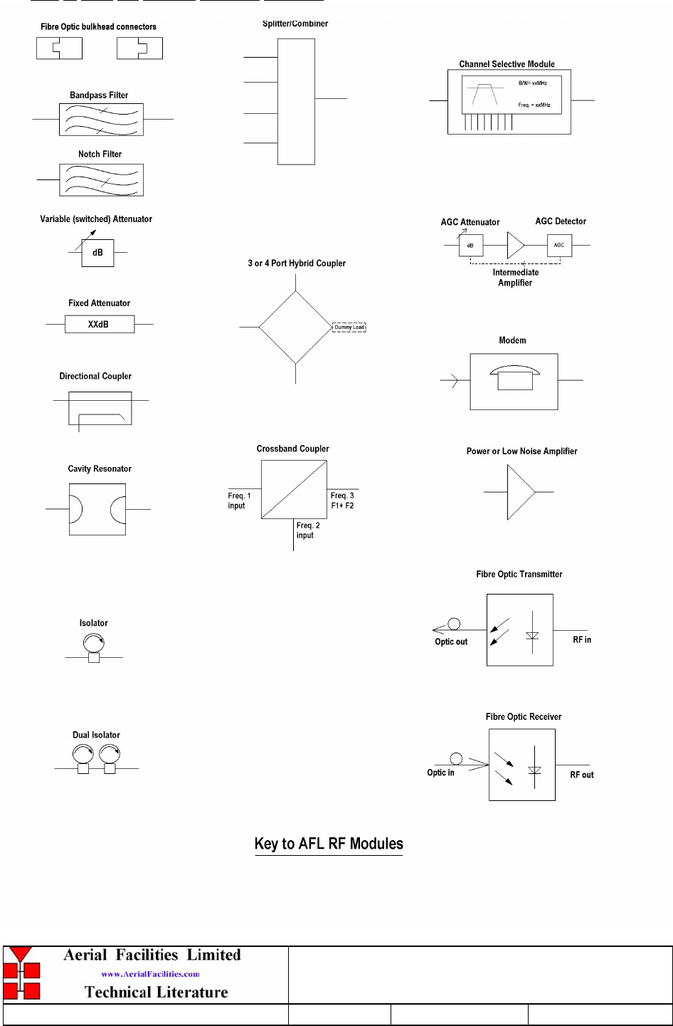
Key to AFL RF Module Drawing Symbols
800MHz & VHF Cell Enhancers
Maintenance Handbook
H/book Number:-50-078001HBKM Issue No:-A Date:-02/09/2004 Page:-10 of 88
1. SAFETY CONSIDERATIONS
1.1 Earthing of Equipment
Cell Enhancers supplied from the mains must be connected to grounded outlets and earthed
in conformity with appropriate local, national and international electricity supply and safety
regulations.
1.2 Electric Shock Hazard
Electrical shocks due to faulty mains driven power supplies.
Whilst ever potentially present in any electrical equipment, such a condition would be
minimised by quality installation practice and thorough testing at:
a) Original assembly
b) Commissioning
c) Regular intervals, thereafter.
All test equipment to be in good working order prior to its use. High current power supplies
can be dangerous because of the possibility of substantial arcing. Always switch off during
disconnection and reconnection.
800MHz & VHF Cell Enhancers
Maintenance Handbook
H/book Number:-50-078001HBKM Issue No:-A Date:-02/09/2004 Page:-11 of 88
1.3 RF Radiation Hazard
RF radiation, (especially at UHF frequencies) arising from transmitter outputs connected to
AFL’s equipment, must be considered a safety hazard.
This condition might only occur in the event of cable disconnection, or because a ‘spare’
output has been left unterminated. Either of these conditions would impair the system’s
efficiency. No investigation should be carried out until all RF power sources have been
removed. This would always be a wise precaution, despite the severe mismatch between the
impedance of an N type connector at 50, and that of free space at 377, which would
severely mitigate against the efficient radiation of RF power. Radio frequency burns could
also be a hazard, if any RF power carrying components were to be carelessly touched!
Antenna positions should be chosen to comply with requirements (both local & statutory)
regarding exposure of personnel to RF radiation. When connected to an antenna, the unit is
capable of producing RF field strengths, which may exceed guideline safe values especially if
used with antennas having appreciable gain. In this regard the use of directional antennas
with backscreens and a strict site rule that personnel must remain behind the screen while the
RF power is on, is strongly recommended.
Where the equipment is used near power lines, or in association with temporary masts not
having lightning protection, the use of a safety earth connected to the case-earthing bolt is
strongly advised.
800MHz & VHF Cell Enhancers
Maintenance Handbook
H/book Number:-50-078001HBKM Issue No:-A Date:-02/09/2004 Page:-12 of 88
1.4 Chemical Hazard
Beryllium Oxide, also known as Beryllium Monoxide, or Thermalox™, is sometimes used
in devices within equipment produced by Aerial Facilities Ltd. Beryllium oxide dust can be
toxic if inhaled, leading to chronic respiratory problems. It is harmless if ingested or by
contact.
Products that contain beryllium are load terminations (dummy loads) and some power
amplifiers. These products can be identified by a yellow and black “skull and crossbones”
danger symbol (shown above). They are marked as hazardous in line with international
regulations, but pose no threat under normal circumstances. Only if a component containing
beryllium oxide has suffered catastrophic failure, or exploded, will there be any danger of the
formation of dust. Any dust that has been created will be contained within the equipment
module as long as the module remains sealed. For this reason, any module carrying the
yellow and black danger sign should not be opened. If the equipment is suspected of failure,
or is at the end of its life-cycle, it must be returned to Aerial Facilities Ltd for disposal.
To return such equipment, please contact the Quality Department, who will give you a
Returned Materials Authorisation (RMA) number. Please quote this number on the packing
documents, and on all correspondence relating to the shipment.
PolyTetraFluoroEthylene, (P.T.F.E.) and P.T.F.E. Composite Materials
Many modules/components in AFL equipment contain P.T.F.E. as part of the RF insulation
barrier.
This material should never be heated to the point where smoke or fumes are evolved. Any
person feeling drowsy after coming into contact with P.T.F.E. especially dust or fumes
should seek medical attention.
1.5 Emergency Contact Numbers
The AFL Quality Department can be contacted on:
Telephone +44 (0)1494 777000
Fax +44 (0)1494 777002
e-mail qa@aerial.co.uk

800MHz & VHF Cell Enhancers
Maintenance Handbook
H/book Number:-50-078001HBKM Issue No:-A Date:-02/09/2004 Page:-13 of 88
2. OVERVIEW/SYSTEM DESCRIPTION
The AFL Channel and/or Band Selective Cell Enhancers are 2-way on-band repeaters.
Various models are available to cover frequency bands from 50MHz to 3000MHz. The
principle sphere of applications is in urban areas where the topology is such that shadows
occur in the propagation pattern (for example within large buildings, conference centres,
road and rail tunnels, etc.)
The frequency bands that are passed by the Cell Enhancer are set as per the specific
customer requirements.
AFL manufacture a wide range of Cell Enhancers, configured for each customer's specific
requirements. Two basic physical variants are available, a rack mounted version to fit in a
standard 19" rack and an environmentally sealed wall mounted version which requires no
further enclosure.
This system provides 800MHz Channelised (x 24) & VHF Simplex/Duplex coverage for the
various concourses platforms and tunnels with a 12V battery backup service (for the
800MHz line amplifier) that will guarantee limited continued coverage in case of mains
power failure.
Each active module is alarm monitored with each shelf/ wall-case having a summary alarm
with a visual ‘alarm active’ indication and a door intrusion alarm included for the wall cases.
All alarms are volt-free, relay contact pairs which may be easily configured into an
RS232/modem system such that automatic remote monitoring by computer may be
achieved.
800MHz & VHF Cell Enhancers
Maintenance Handbook
H/book Number:-50-078001HBKM Issue No:-A Date:-02/09/2004 Page:-14 of 88
3. SPECIFICATION
3.P Photographs
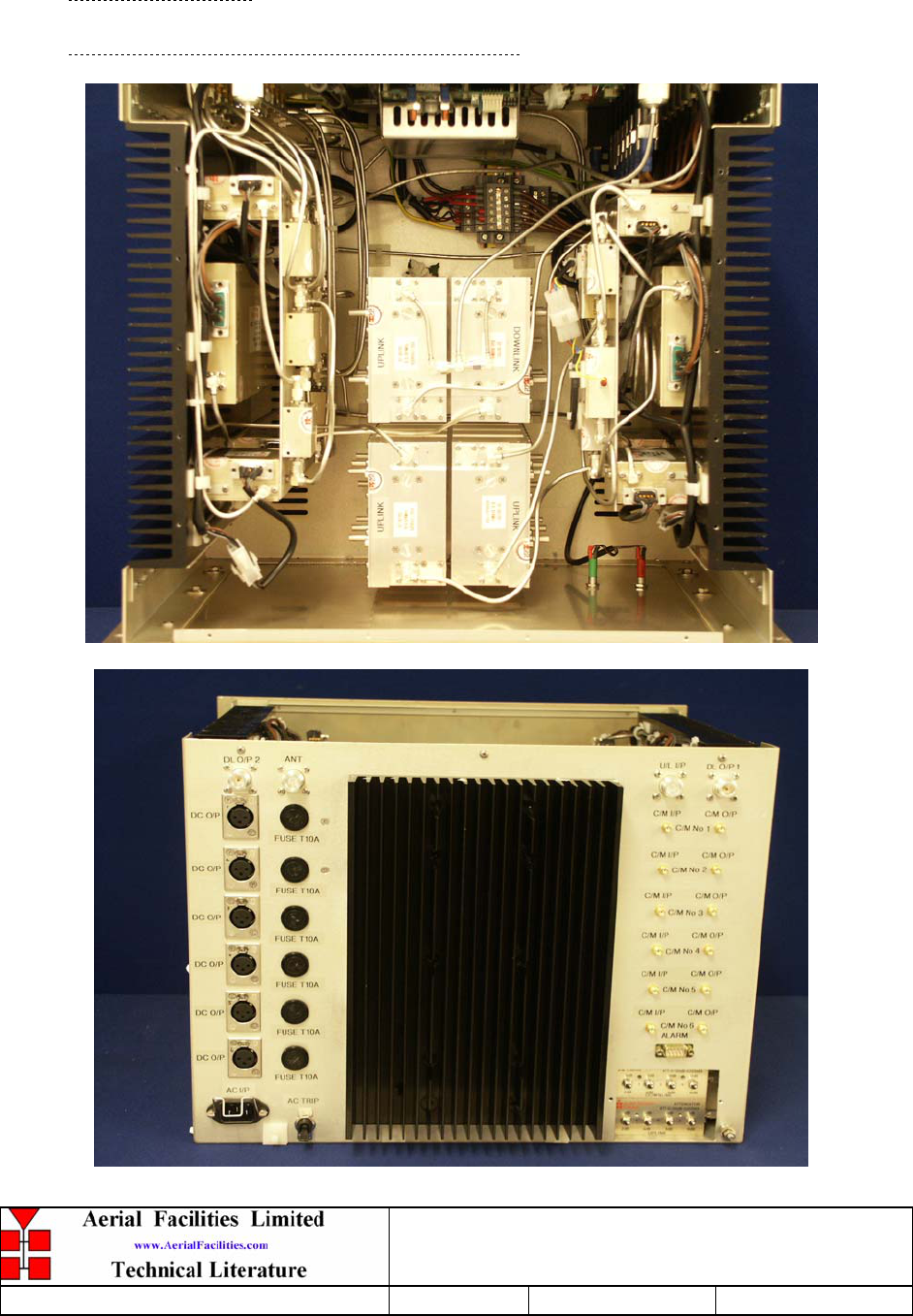
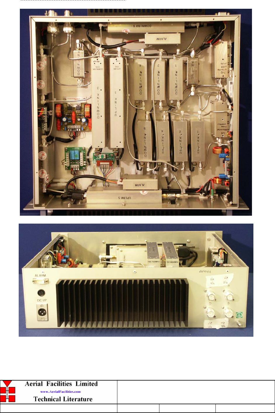
3.P.1 800MHz Air I/F Uplink Shelf 50-078002

800MHz & VHF Cell Enhancers
Maintenance Handbook
H/book Number:-50-078001HBKM Issue No:-A Date:-02/09/2004 Page:-15 of 88
3.P.2 Eight Channel Downlink Shelf 50-078003
Photos of this shelf are unavailable
800MHz & VHF Cell Enhancers
Maintenance Handbook
H/book Number:-50-078001HBKM Issue No:-A Date:-02/09/2004 Page:-16 of 88
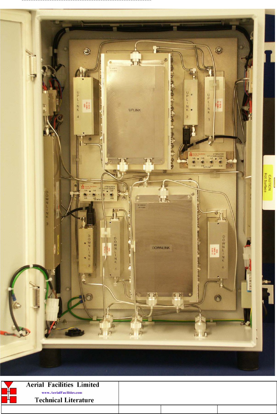
3.P.3 Power Amplifier/Driver Shelf 50-078004
800MHz & VHF Cell Enhancers
Maintenance Handbook
H/book Number:-50-078001HBKM Issue No:-A Date:-02/09/2004 Page:-17 of 88
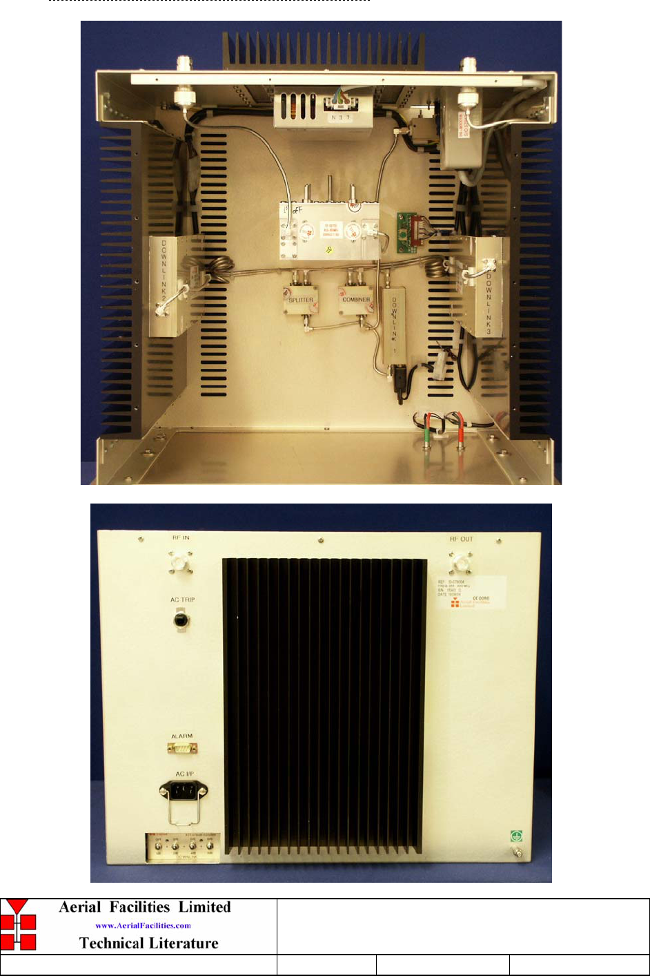
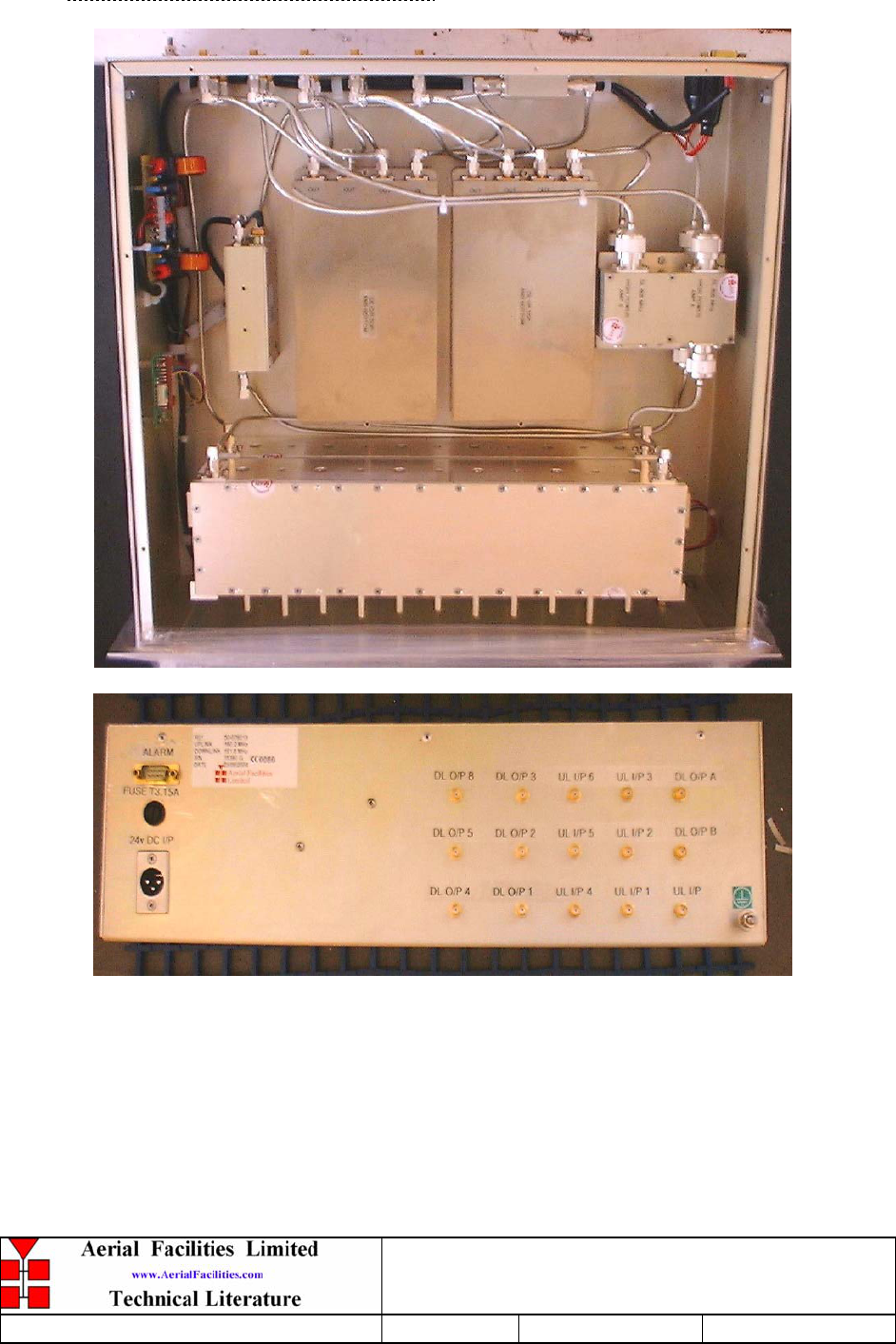
3.P.4 800MHz In-Line Amplifier 50-078017

800MHz & VHF Cell Enhancers
Maintenance Handbook
H/book Number:-50-078001HBKM Issue No:-A Date:-02/09/2004 Page:-18 of 88
3.P.5 VHF/800MHz Multi-Coupler Shelf 50-078015
Photos of this shelf are unavailable
800MHz & VHF Cell Enhancers
Maintenance Handbook
H/book Number:-50-078001HBKM Issue No:-A Date:-02/09/2004 Page:-19 of 88
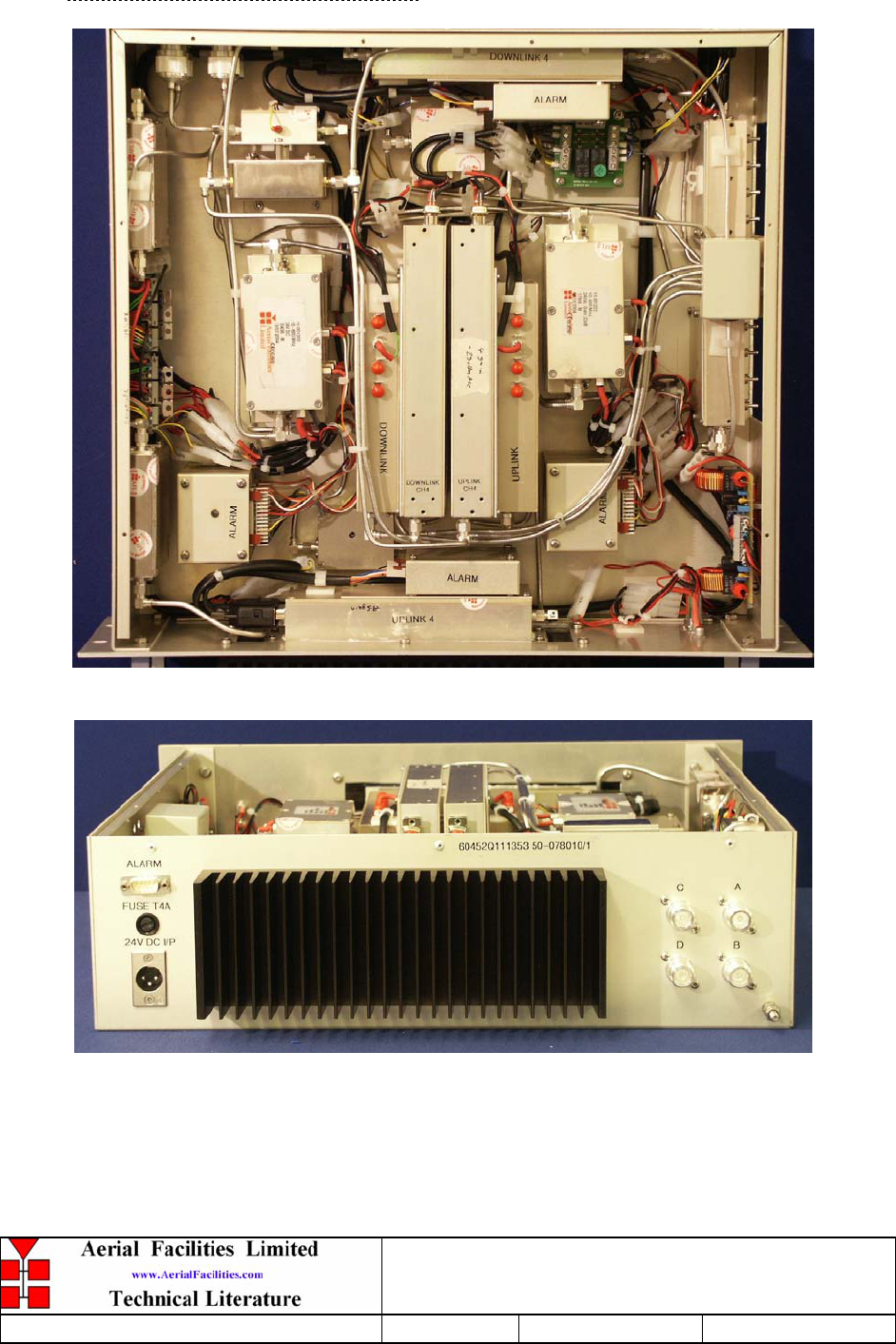
3.P.6 VHF Simplex Shelf 50-078010
There are two different types of simplex shelves 50-078010/1 & 50-078010/2, they differ
only in the frequencies they process.
800MHz & VHF Cell Enhancers
Maintenance Handbook
H/book Number:-50-078001HBKM Issue No:-A Date:-02/09/2004 Page:-20 of 88
3.P.7 VHF Duplex Shelf 50-078011
There are four different types of duplex shelves 50-078011/1,2,3 & 4 they differ only in
the frequencies they process.

800MHz & VHF Cell Enhancers
Maintenance Handbook
H/book Number:-50-078001HBKM Issue No:-A Date:-02/09/2004 Page:-21 of 88
3.P.8 VHF Air Interface Shelf 50-078012
Photos of this shelf are unavailable.
800MHz & VHF Cell Enhancers
Maintenance Handbook
H/book Number:-50-078001HBKM Issue No:-A Date:-02/09/2004 Page:-22 of 88
3.P.9 VHF Combiner Shelf 50-078013
800MHz & VHF Cell Enhancers
Maintenance Handbook
H/book Number:-50-078001HBKM Issue No:-A Date:-02/09/2004 Page:-23 of 88
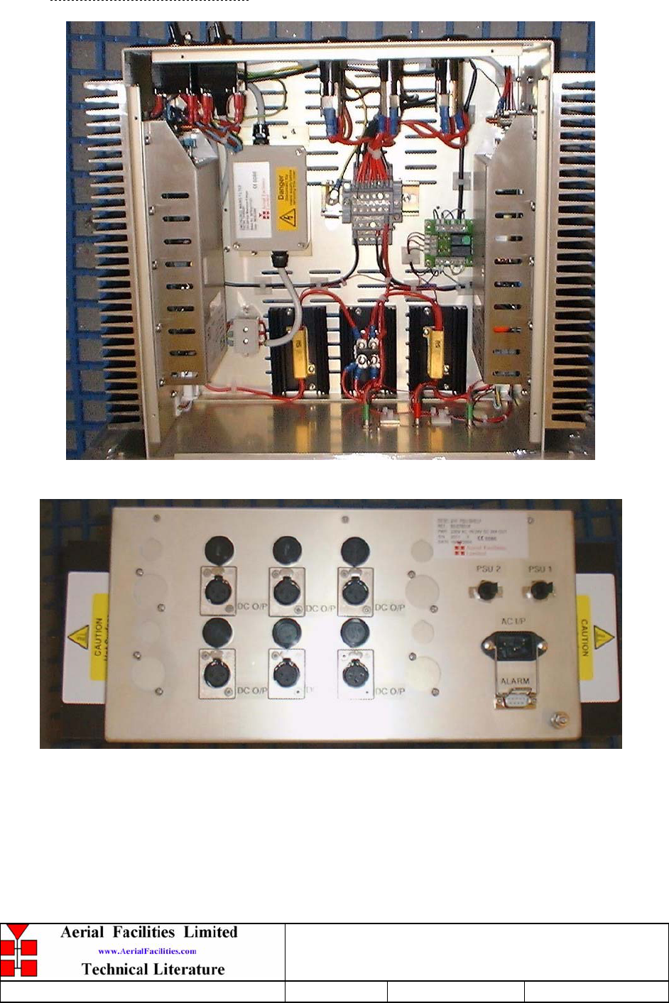
3.P.10 PSU Shelf 50-078014
800MHz & VHF Cell Enhancers
Maintenance Handbook
H/book Number:-50-078001HBKM Issue No:-A Date:-02/09/2004 Page:-24 of 88
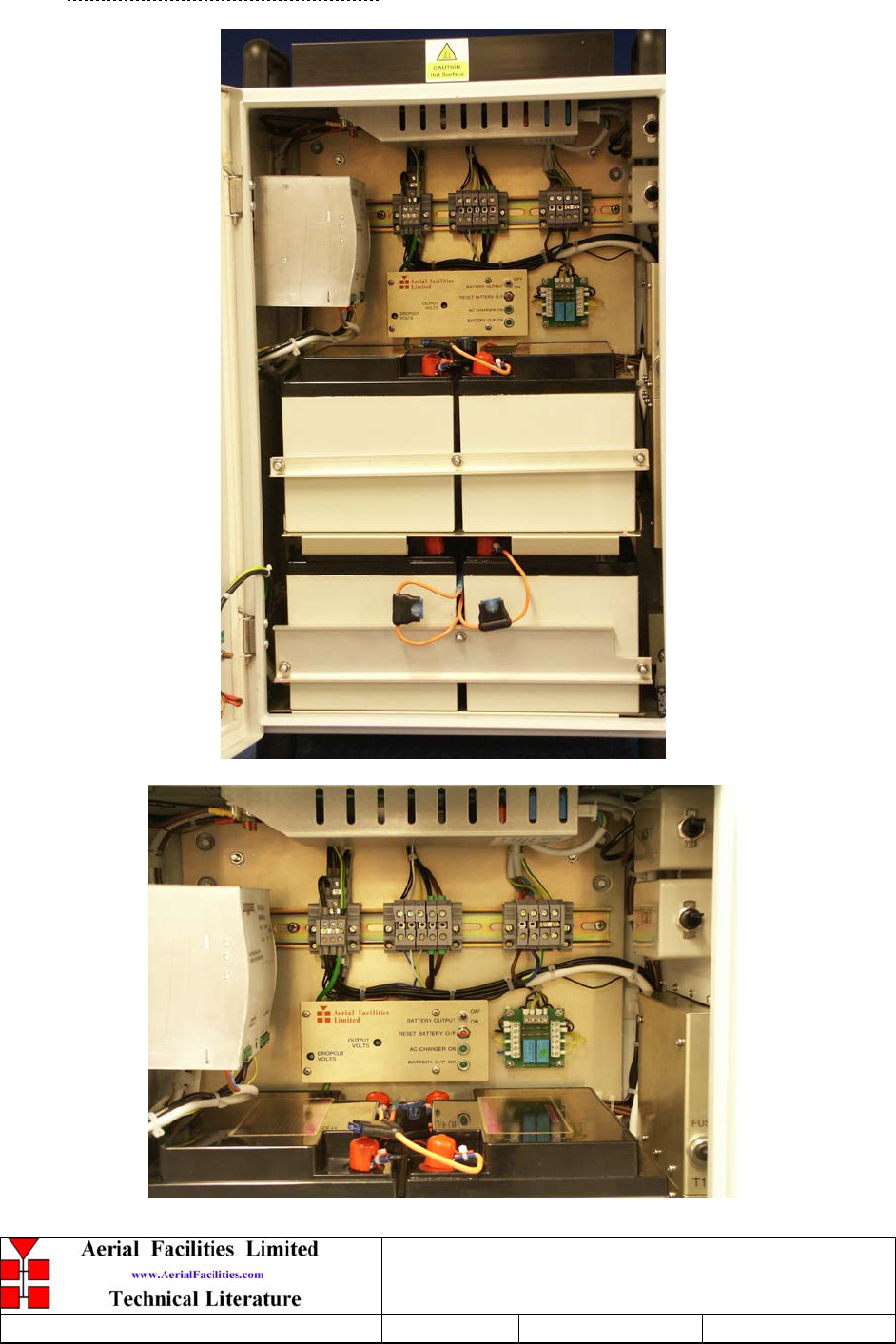
3.P.11 Battery Backup 80-209302
800MHz & VHF Cell Enhancers
Maintenance Handbook
H/book Number:-50-078001HBKM Issue No:-A Date:-02/09/2004 Page:-25 of 88
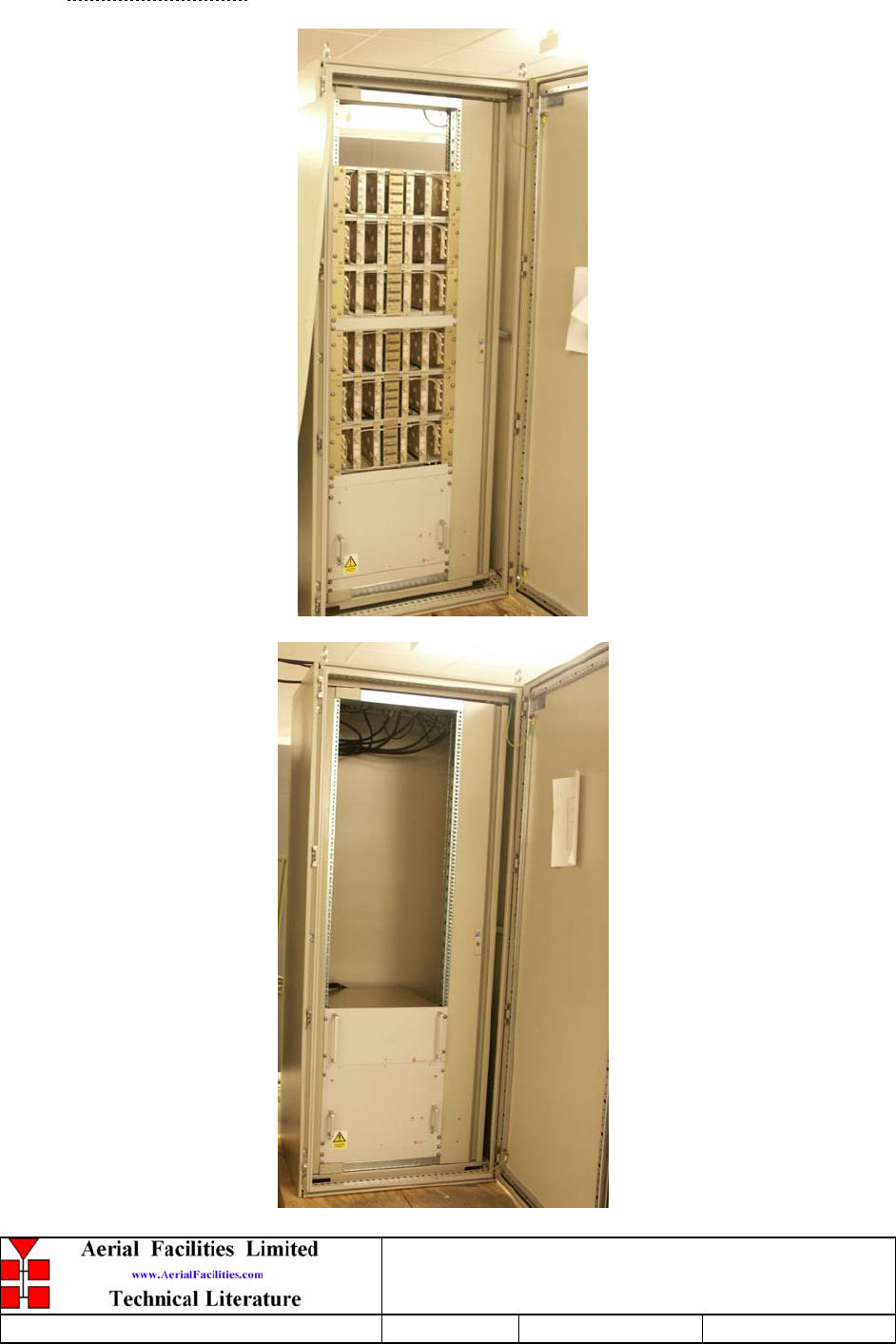
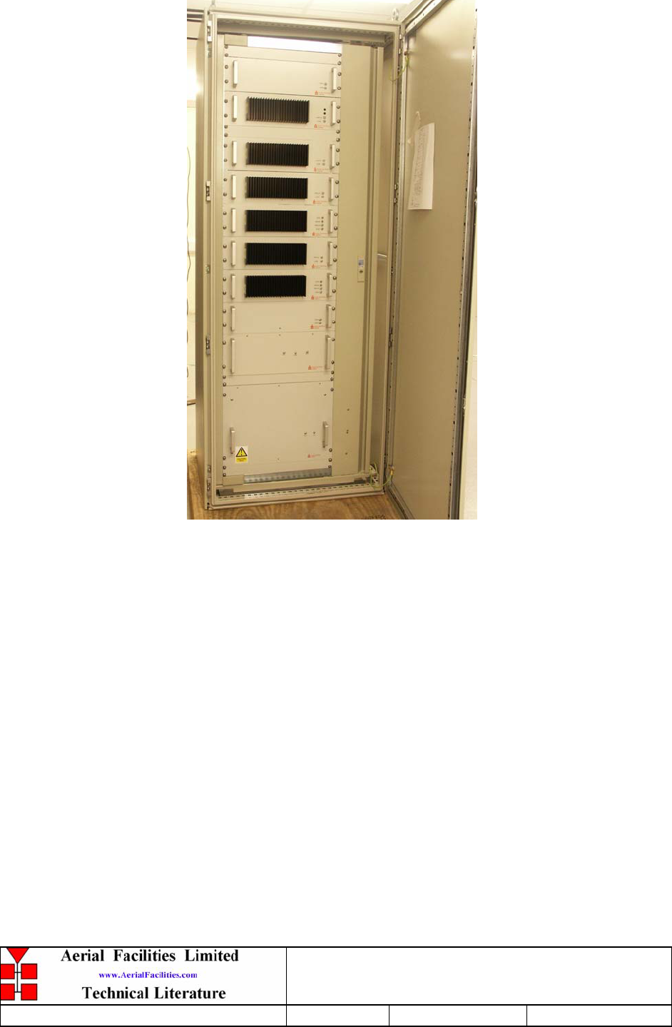
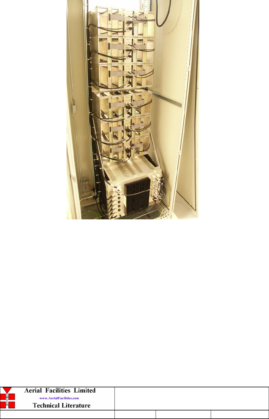
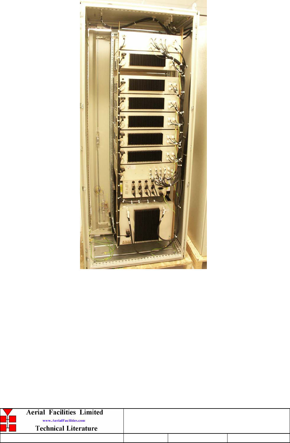
3.P.12 Rack Photos
800MHz & VHF Cell Enhancers
Maintenance Handbook
H/book Number:-50-078001HBKM Issue No:-A Date:-02/09/2004 Page:-26 of 88
800MHz & VHF Cell Enhancers
Maintenance Handbook
H/book Number:-50-078001HBKM Issue No:-A Date:-02/09/2004 Page:-27 of 88
800MHz & VHF Cell Enhancers
Maintenance Handbook
H/book Number:-50-078001HBKM Issue No:-A Date:-02/09/2004 Page:-28 of 88
800MHz & VHF Cell Enhancers
Maintenance Handbook
H/book Number:-50-078001HBKM Issue No:-A Date:-02/09/2004 Page:-29 of 88
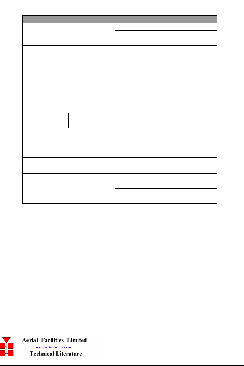
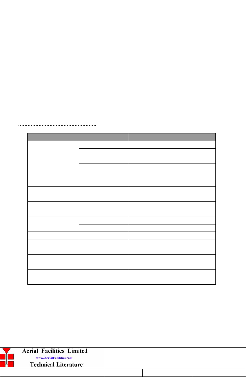
3.1 Electrical Specification
PARAMETER SPECIFICATION
851-869MHz (Downlink)
Frequency range: 806-824MHz (Uplink)
160.2-161.8MHz (Simplex/Duplex)
18MHz (UHF)
Bandwidth: 1.6MHz (VHF)
>100dB (Uplink)
Gain: >90dB (Downlink)
Gain Adjustment: 0 - 30dB (in 2dB steps)
>5.0Watts (UHF)
Uplink Power: >5.0Watts (VHF)
>40.0Watts (UHF)
Downlink Power >5.0Watts (VHF)
Uplink +43dBm
IP3: Downlink +50dBm
Noise Figure: <6dB
AGC: -25dBm (factory set in channel module
)
VSWR: better than 1.5:1
RF Connectors: N type, female
operational: -10°C to +55°C
Temperature range storage: -40°C to +70°C
1 PSU’s
2 Amplifiers
3 Channel modules
Alarms Fitted:
(non-latching, volt-free relay
contacts/TTL) 4 Door (Wall mount cases)
800MHz & VHF Cell Enhancers
Maintenance Handbook
H/book Number:-50-078001HBKM Issue No:-A Date:-02/09/2004 Page:-30 of 88
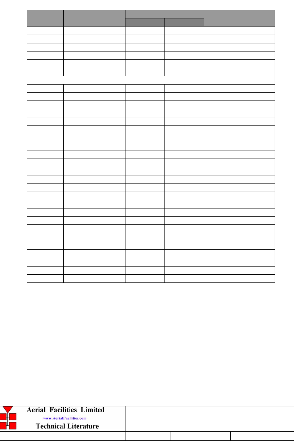
3.2 Channel Frequency Listing
Frequencies (MHz) Channel
No.
User
Group Downlink Uplink Status
1 SD Trolley 160.6650 160.9350 Duplex
2 SD Trolley 160.3800 160.9050 Duplex (Note1)
3 SD Trolley 160.7100 161.4150 Duplex
4 SD Trolley 161.2950 161.2950 Simplex
5 SD Trolley 161.5650 160.7550 Duplex
6 SD Trolley 160.5300 160.5300 Simplex
800 MHz Band
1 SD City (PD/FD) 860.0500 815.0500 Duplex
2 SD City (PD/FD) 860.0250 815.0250 Duplex
3 SD City (PD/FD) 859.0500 814.0500 Duplex
4 SD City (PD/FD) 859.0250 814.0250 Duplex
5 SD City (PD/FD) 858.0500 813.0500 Duplex (Note 2)
6 SD City (PD/FD) 858.0250 813.0250 Duplex (Note 2)
7 SD City (PD/FD) 857.0500 812.0500 Duplex
8 SD City (PD/FD) 860.0000 815.0000 Duplex
9 SD City (PD/FD) 859.0000 814.0000 Duplex
10 SD City (PD/FD) 858.0000 813.0000 Duplex (Note 2)
11 SD City (PD/FD) 857.0250 812.0250 Duplex
12 SD City (PD/FD) 857.0000 812.0000 Duplex
13 SD City (PD/FD) 856.0500 811.0500 Duplex
14 SD City (PD/FD) 856.0250 811.0250 Duplex
15 SD City (PD/FD) 862.0500 817.0500 Duplex
16 SD City (PD/FD) 862.1000 817.1000 Duplex
17 SD City (PD/FD) 863.0500 818.0500 Duplex
18 SD City (PD/FD) 864.0500 819.0500 Duplex
19 SD City (PD/FD) 865.5000 820.0500 Duplex
20 SDSU Security 868.5750 823.5750 Duplex (Note 4)
21 SDSU Security 866.3875 821.3875 Duplex (Note 4)
22 SD City (PD/FD)
0
0 811.1500 Duplex (Note 3)
23 TBD TBD TBD TBD
24 TBD TBD TBD TBD
Note 1: Channel 2 uplink frequency was changed to 160.9050 MHz from 161.9050MHz as
required by the Authority.
Note 2: Channel 4, 5 & 10 uplink frequency changed to 813.0500 MHz, 813.0250MHz, &
813.0000MHz from 816.050 MHz, 816.0250MHz & 816.000MHz respectively.
Note 3: Channel 22 is new frequency pair for SD City with 25KHz channel spacing.
Note 4: Channel 20 & 21 are analogue radio system with digital modulation (3600bps) and the
donor site for these channels has azimuth of 150 degree. The Azimuth of CH 1 to Ch 19
and the new CH 22 is 40 degree.
800MHz & VHF Cell Enhancers
Maintenance Handbook
H/book Number:-50-078001HBKM Issue No:-A Date:-02/09/2004 Page:-31 of 88
3.3 Mechanical Specifications
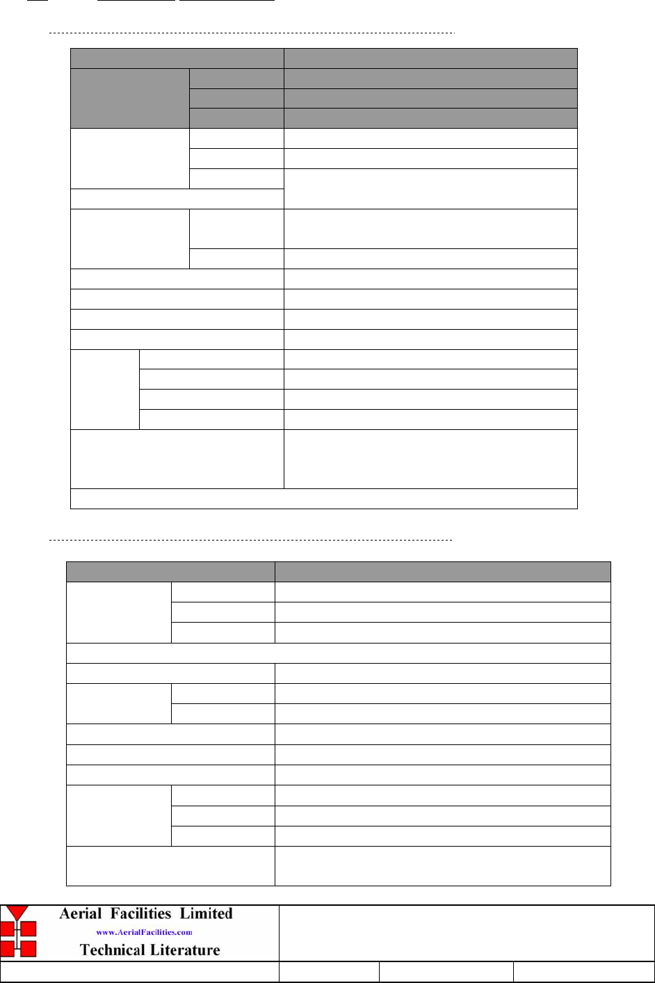
3.3.1 Rack Mounted Equipment Mechanical Specifications
PARAMETER SPECIFICATION
Height: 40U Standard Eurorack
Width: 19" (482.6mm)
Rack
Depth: 600mm (800 optional)
Height: See parts lists
Width: 19" (482.6mm)
Shelves:
Depth:
<400mm(excluding heatsinks, connectors,
handles and feet)
operational
:
-10°C to +55°C
Temperature
Range: storage: -40°C to +70°C
Weight: >5-15*kg
Humidity: 5 – 95% non-condensing
RF Connectors: N type female
Environmental Protection: IP54
Case: Alocrom
Heatsinks: Matt black
Handles: Alloy
Finish:
Fascias Painted to RAL7032
Supply Cable:
Unit supplied with suitable supply input
leads, connector and specified length of
cable (where appropriate)
* Note: Individual shelf weight not specified.
3.3.2 Wall Mounted Equipment (50-078017 & 80-209302)
PARAMETER SPECIFICATION
Height: 620mm
Width: 420mm
Case size
Depth: 250mm
(excluding heatsinks, connectors, handles and feet)
Fixings: 4 holes on 470(w) x 500(h)mm
operational: -10°C to +60°C Temperature
Range: storage: -40°C to +70°C
Weight: >30kg
RF Connectors: N type female
Environmental Protection: IP65 (with door closed and all ports terminated)
Case: To RAL 7032/5
Heatsinks: Matt black (where fitted)
Finish:
Handles: Black Technopolymer
Supply Cable: Unit supplied with suitable supply input leads
with connector and appropriate length of cable.
800MHz & VHF Cell Enhancers
Maintenance Handbook
H/book Number:-50-078001HBKM Issue No:-A Date:-02/09/2004 Page:-32 of 88
3.4 Parts Lists
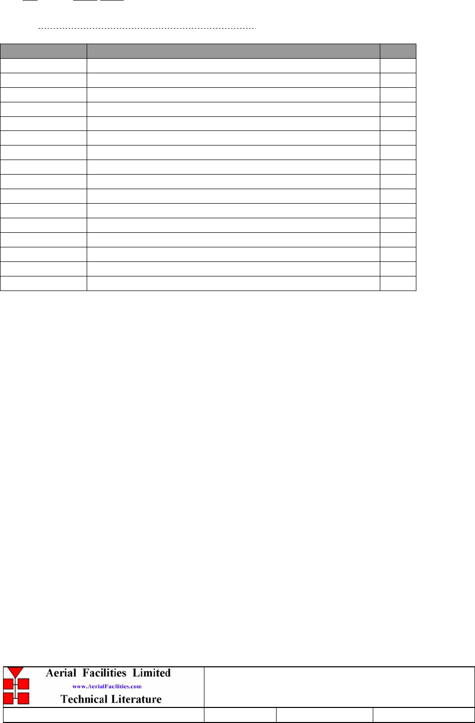
3.4.1 Whole System Parts List (50-078001)
AFL Part Nō. Part Description Qty.
50-078002 800MHz AIR I/F + BSCE UPLINK SHELF 1
50-078003 800MHz 8CH CHANNEL MOD. SHELF 3
50-078004 800MHz 40W HPA / DRIVER SHELF 2
50-078010/1 VHF SIMPLEX SHELF 1
50-078010/2 VHF SIMPLEX SHELF 1
50-078011/1 VHF DUPLEX SHELF 1
50-078011/2 VHF DUPLEX SHELF 1
50-078011/3 VHF DUPLEX SHELF 1
50-078011/4 VHF DUPLEX SHELF 1
50-078012 VHF AIR I/F SHELF 1
50-078013 VHF COMBINER SHELF 1
50-078014 VHF PSU SHELF 1
50-078015 VHF/ 800 Tx MULTICOUPLER 1
50-078017 800MHz IN LINE AMPLIFIER 2
60-020608 40U SWING FRAME CABINET Q104362 3
80-209302 12V 160Ah BATTERY BACK UP STANDARD 2

800MHz & VHF Cell Enhancers
Maintenance Handbook
H/book Number:-50-078001HBKM Issue No:-A Date:-02/09/2004 Page:-33 of 88
3.4.2 800MHz AIF Uplink Shelf 50-078002 Parts List
AFL Part Nō. Part Description Qty.
02-007201 900MHz 8POLE 10-20MHz B/W SMA 4
05-002602 900MHz SPLITTER/COMBINER, 20W 5
05-003801 3WAY GEN.SPLIT 900MHz GEN.ASS 4
10-000701 1/4W0-30dB SWITCHED ATTENUATOR 2
11-005902 900MHz LOW NOISE AMP WITH RELAY ASS 3
11-006702 GA 800-1000MHz LNA 29dB (WITH RELAY 4
12-018001 PA 800-960MHz 10W 30dB 2
14-000225 CASE RAIL LONG R.S.A./R.F.A. 4
17-001109 CE AGC UNIT LOG DET/AMP ASSY (12v) 1
17-001201 C/E AGC UNIT ATTENUATOR ASSY 1
20-001601 12V RELAY BOARD 1
50-012820 CCE RACK MOUNTED 8U CHASSIS 1
50-012822 CCE RACK MOUNTED LID 1
50-012825 CCE RACK MOUNTED HEATSINK BRACKET 4
50-027720 RACK MTD CHAN C.E. MODIFIED HEATSIN 2
80-090822 C/E 8U FRONT PANEL, AFL (RAL7035) 1
80-310420 BCC 400W POWER SUPPLY HEATSINK 1
91-030002 N ADAPTOR PANEL FEMALE:FEMALE 4
91-130005 SMA BULKHEAD ADAPTOR F/F 12
91-500025 3 PIN RIGHT ANGLE FREE PLUG NC-X 3
91-510003 3 PIN R.ANGLE FREE SOC.NC-X. 3
91-510004 3 PIN PNL.MOUNT SOCKET NC-X 3
91-510032 20A SOCKET CONTACT PIN 4
91-520001 PWR MAINS INL FIXED/SOLD.TERMS 1
91-520005 MAINS LEAD (KETTLE, IEC) 1
91-520010 MAINS RETAINING CLIP 1
91-600007 'D' 9 WAY BLACK SHELL 8
91-600014 'D' 9 WAY SOCKET S/B (NON FILTERED) 7
91-600015 'D' 9 WAY PLUG S/B (NON FILTERED) 1
91-660001 2W5 MIXED D TYPE SOCKET (7 WAY) 2
96-110034 FUSE HOLDER 16-30A, 32mm BODY 3
96-300057 15V 27A PSU 400W (XP BCC) 1
96-700034 LED RED 5mm IP67 INTEGRAL RES. 24V 1
96-700035 LED GREEN 5mm IP67 INTEGRAL RES 24V 1
96-900018 AC TRIP SWITCH (5 AMP M.C.B.) 2
97-400005 HANDLE TYPE H6802 3U [ALLOY] 2
99-200008 DANGER HIGH VOLTAGE LABEL 2x2' 1
99-200017 CAUTION HEAVY LABEL 75x55mm 2
800MHz & VHF Cell Enhancers
Maintenance Handbook
H/book Number:-50-078001HBKM Issue No:-A Date:-02/09/2004 Page:-34 of 88
3.4.3 800MHz 8 Channel, Channel Module Shelf 50-078003 Parts List
AFL Part Nō. Part Description Qty.
05-003302 4 WAY SPLITTER GSM 900MHz 4
17-002101 CHANNEL CONTROL MODULE 2
17-002103 26WAY RIBBON CABLE LEAD 8
17-003022 MODULE PATTERNED LEAVE 8
17-003023 SUBRACK SIDE PANEL 4
17-003024 SUBRACK REAR BRACKET 8
17-003025 BOTTOM MODULE GUIDE 8
17-003028 MODULE SQUARE LEAVE 8
17-003029 TOP MODULE GUIDE 8
17-009127 CHAN MOD 810-860MHz 30KHz 8p TCXO 8
91-100004 SMA PLUG ELBOW UT-85/RG405 32
91-500001 POWER PLG 3 PIN PNL.MOUNT NC-X 2
91-510003 3 PIN R.ANGLE FREE SOC.NC-X. 2
91-600007 'D' 9 WAY BLACK SHELL 4
91-600014 'D' 9 WAY SOCKET S/B (NON FILTERED) 2
91-600015 'D' 9 WAY PLUG S/B (NON FILTERED) 2
92-280033 Captive Screw 16
96-110001 FUSE HOLDER 20 x 5mm6.3A 2
96-110007 T 1.6A A.SURGE FUSE 20mm 4
97-000002 BLACK MODULE CAGE RUNNER 16
97-600001 SUBRACK FRONT HORIZ 4
97-600002 SUBRACK M2.5 STD TAP 4

800MHz & VHF Cell Enhancers
Maintenance Handbook
H/book Number:-50-078001HBKM Issue No:-A Date:-02/09/2004 Page:-35 of 88
3.4.4 800MHz 40W Amplifier Shelf 50-078004 Parts List
AFL Part Nō. Part Description Qty.
02-007201 900MHz 8POLE 10-20MHz B/W SMA 1
05-002602 900MHz SPLITTER/COMBINER, 20W 2
10-000901 SW. ATTENUATOR 0.25W 0-15dB 1
11-005802 900MHz DRIVER STAGE WITH RELAY 1
12-018002 PA 800-960MHz 20W CLASS A 2
14-000225 CASE RAIL LONG R.S.A./R.F.A. 2
50-012820 CCE RACK MOUNTED 8U CHASSIS 1
50-012822 CCE RACK MOUNTED LID 1
50-012825 CCE RACK MOUNTED HEATSINK BRACKET 4
50-027720 RACK MTD CHAN C.E. MODIFIED HEATSIN 2
80-090822 C/E 8U FRONT PANEL, AFL (RAL7035) 1
80-310420 BCC 400W POWER SUPPLY HEATSINK 1
91-030002 N ADAPTOR PANEL FEMALE:FEMALE 2
91-510032 20A SOCKET CONTACT PIN 4
91-520001 PWR MAINS INL FIXED/SOLD.TERMS 1
91-520005 MAINS LEAD (KETTLE, IEC) 1
91-520010 MAINS RETAINING CLIP 1
91-600007 'D' 9 WAY BLACK SHELL 1
91-600014 'D' 9 WAY SOCKET S/B (NON FILTERED) 1
91-600015 'D' 9 WAY PLUG S/B (NON FILTERED) 1
91-660001 2W5 MIXED D TYPE SOCKET (7 WAY) 2
96-300057 15V 27A PSU 400W (XP BCC) 1
96-700034 LED RED 5mm IP67 INTEGRAL RES. 24V 1
96-700035 LED GREEN 5mm IP67 INTEGRAL RES 24V 1
96-900018 AC TRIP SWITCH (5 AMP M.C.B.) 1
97-400005 HANDLE TYPE H6802 3U [ALLOY] 2
99-200008 DANGER HIGH VOLTAGE LABEL 2x2' 1
99-200017 CAUTION HEAVY LABEL 75x55mm 2

800MHz & VHF Cell Enhancers
Maintenance Handbook
H/book Number:-50-078001HBKM Issue No:-A Date:-02/09/2004 Page:-36 of 88
3.4.5 VHF Simplex Shelf 50-078010/1
AFL Part Nō. Part Description Qty.
08-930002 2 PORT ISOLATOR 150-300MHz SMA 2
10-000901 SW. ATTENUATOR 0.25W 0-15dB 4
11-001202 10/600MHz LNA 24v SMA Alarm 7
12-002213 3 STAGE ALARM/SIMPLEXMUTE PCB SUB-ASS 2
12-002220 3 STAGE ALARM PCB COVER 2
12-002804 SINGLE CH. ALARM/SIMPLEX MUTE BOARD 7
12-002820 SINGLE CHANNEL ALARM COVER 7
12-004902 POWER AMP VHF 5W CLASS AB 2
13-001803 DUAL DC/DC CONVERTER 24V-12V 1A 1
13-001822 DC-DC CON 24V-5V/15V COVER 1
13-002811 SIMPLEX CONTROLLER PCB ASSEMBLY 2
17-001201 C/E AGC UNIT ATTENUATOR ASSY 4
17-002802 SIMPLEX C.E Rx/SQUELCH & AF (SMD) 2
17-009135 VHF 15Kstep CH MOD 15kHz 8p BW+IFRX 2
19-000826 2U,3U,4U 19" UNIT 400 DEEP LID 1
19-000921 3U 19" UNIT 400 DEEP CHASSIS + BKT 1
19-000924 3U 19" UNIT FRONT PANEL FAB 1
80-063920 HEATSINK 2U ASS140 (5W) MILCHBUCK 2
91-030002 N ADAPTOR PANEL FEMALE:FEMALE 4
91-500001 POWER PLG 3 PIN PNL.MOUNT NC-X 1
91-510003 3 PIN R.ANGLE FREE SOC.NC-X. 1
91-600001 'D'TYPE 9 WAY PLUG S/B TERM 1
91-600014 'D' 9 WAY SOCKET S/B (NON FILTERED) 2
91-620001 'D' 25 WAY SOCKET S/B TERM 2
91-700017 ICD 15 WAY 0.1' CONNECTOR 9
93-540035 1K3 0.25W 1% RES MRS25 M:F 2
93-980109 161.295MHz CRYSTAL FILT FAN4M52500 4
96-110001 FUSE HOLDER 20 x 5mm6.3A 1
96-300014 PSU VOLTS ADJUSTER 2
96-700017 LED AMBER 5mm SEALED IP66 2
96-700034 LED RED 5mm IP67 INTEGRAL RES. 24V 1
96-700035 LED GREEN 5mm IP67 INTEGRAL RES 24V 1
97-400005 HANDLE TYPE H6802 3U [ALLOY] 2

800MHz & VHF Cell Enhancers
Maintenance Handbook
H/book Number:-50-078001HBKM Issue No:-A Date:-02/09/2004 Page:-37 of 88
3.4.6 VHF Simplex Shelf 50-078010/2 Parts List
AFL Part Nō. Part Description Qty.
08-930002 2 PORT ISOLATOR 150-300MHz SMA 2
10-000901 SW. ATTENUATOR 0.25W 0-15dB 4
11-001202 10/600MHz LNA 24v SMA Alarm 7
12-002213 3 STAGE ALM/SIMPLEXMUTE PCB SUB-ASS 2
12-002220 3 STAGE ALARM PCB COVER 2
12-002804 SINGLE CH. ALARM/SIMPLEX MUTE BOARD 7
12-002820 SINGLE CHANNEL ALARM COVER 7
12-004902 POWER AMP VHF 5W CLASS AB 2
13-001803 DUAL DC/DC CONVERTER 24V-12V 1A 1
13-001822 DC-DC CON 24V-5V/15V COVER 1
13-002811 SIMPLEX CONTROLLER PCB ASSEMBLY 2
17-001201 C/E AGC UNIT ATTENUATOR ASSY 4
17-002802 SIMPLEX C.E Rx/SQUELCH & AF (SMD) 2
17-009135 VHF 15Kstep CH MOD 15kHz 8p BW+IFRX 2
19-000826 2U,3U,4U 19" UNIT 400 DEEP LID 1
19-000921 3U 19" UNIT 400 DEEP CHASSIS + BKT 1
19-000924 3U 19" UNIT FRONT PANEL FAB 1
80-063920 HEATSINK 2U ASS140 (5W) MILCHBUCK 2
91-030002 N ADAPTOR PANEL FEMALE:FEMALE 4
91-500001 POWER PLG 3 PIN PNL.MOUNT NC-X 1
91-510003 3 PIN R.ANGLE FREE SOC.NC-X. 1
91-600001 'D'TYPE 9 WAY PLUG S/B TERM 1
91-600014 'D' 9 WAY SOCKET S/B (NON FILTERED) 2
91-620001 'D' 25 WAY SOCKET S/B TERM 2
91-700017 ICD 15 WAY 0.1' CONNECTOR 9
93-540035 1K3 0.25W 1% RES MRS25 M:F 2
93-980112 160.530MHz CRYSTAL FILT FAN4M52500 4
96-110001 FUSE HOLDER 20 x 5mm6.3A 1
96-300014 PSU VOLTS ADJUSTER 2
96-700017 LED AMBER 5MM SEALED IP66 2
96-700034 LED RED 5mm IP67 INTEGRAL RES. 24V 1
96-700035 LED GREEN 5mm IP67 INTEGRAL RES 24V 1
97-400005 HANDLE TYPE H6802 3U [ALLOY] 2

800MHz & VHF Cell Enhancers
Maintenance Handbook
H/book Number:-50-078001HBKM Issue No:-A Date:-02/09/2004 Page:-38 of 88
3.4.7 VHF Duplex Shelf 50-078011/1 Parts List
AFL Part Nō. Part Description Qty.
08-930002 2 PORT ISOLATOR 150-300MHz SMA 2
10-000901 SW. ATTENUATOR 0.25W 0-15dB 4
11-006002 LNA VHF 70-500MHz WITH RELAY 7
12-002201 3 STAGE AMPLIFIER ALARM BOARD 1
12-002203 3 STAGE ALARM BOARD SIMPLEX 1
12-002220 3 STAGE ALARM PCB COVER 2
12-004902 POWER AMP VHF 5W CLASS AB 2
13-001803 DUAL DC/DC CONVERTER 24V-12V 1A 2
13-001822 DC-DC CON 24V-5V/15V COVER 1
13-002812 SWITCH VERSION OF SIMPLEX CONT. 1
17-001105 CE AGC UNIT LOG DET/AMP ASSY (24v) 1
17-009135 VHF 15Kstep CH MOD 15kHz 8p BW+IFRX 2
19-000826 2U,3U,4U 19" UNIT 400 DEEP LID 1
19-000921 3U 19" UNIT 400 DEEP CHASSIS + BKT 1
19-000924 3U 19" UNIT FRONT PANEL FAB 1
80-063920 HEATSINK 2U ASS140 (5W) MILCHBUCK 2
91-030002 N ADAPTOR PANEL FEMALE:FEMALE 4
91-500001 POWER PLG 3 PIN PNL.MOUNT NC-X 1
91-510003 3 PIN R.ANGLE FREE SOC.NC-X. 1
91-600001 'D'TYPE 9 WAY PLUG S/B TERM 1
91-600014 'D' 9 WAY SOCKET S/B (NON FILTERED) 7
91-620001 'D' 25 WAY SOCKET S/B TERM 2
91-700017 ICD 15 WAY 0.1' CONNECTOR 2
93-980103 160.665MHz CRYSTAL FILT FAN4M52500 2
93-980104 160.935MHz CRYSTAL FILT FAN4M52500 2
96-110001 FUSE HOLDER 20 x 5mm6.3A 1
96-700034 LED RED 5mm IP67 INTEGRAL RES. 24V 1
96-700035 LED GREEN 5mm IP67 INTEGRAL RES 24V 1
97-400005 HANDLE TYPE H6802 3U [ALLOY] 2
800MHz & VHF Cell Enhancers
Maintenance Handbook
H/book Number:-50-078001HBKM Issue No:-A Date:-02/09/2004 Page:-39 of 88
3.4.8 VHF Duplex Shelf 50-078011/2 Parts List
AFL Part Nō. Part Description Qty.
08-930002 2 PORT ISOLATOR 150-300MHz SMA 2
10-000901 SW. ATTENUATOR 0.25W 0-15dB 4
11-006002 LNA VHF 70-500MHz WITH RELAY 7
12-002201 3 STAGE AMPLIFIER ALARM BOARD 1
12-002203 3 STAGE ALARM BOARD SIMPLEX 1
12-002220 3 STAGE ALARM PCB COVER 2
12-004902 POWER AMP VHF 5W CLASS AB 2
13-001803 DUAL DC/DC CONVERTER 24V-12V 1A 2
13-001822 DC-DC CON 24V-5V/15V COVER 1
13-002812 SWITCH VERSION OF SIMPLEX CONT. 1
17-001105 CE AGC UNIT LOG DET/AMP ASSY (24v) 1
17-009135 VHF 15Kstep CH MOD 15kHz 8p BW+IFRX 2
19-000826 2U,3U,4U 19" UNIT 400 DEEP LID 1
19-000921 3U 19" UNIT 400 DEEP CHASSIS + BKT 1
19-000924 3U 19" UNIT FRONT PANEL FAB 1
80-063920 HEATSINK 2U ASS140 (5W) MILCHBUCK 2
91-030002 N ADAPTOR PANEL FEMALE:FEMALE 4
91-500001 POWER PLG 3 PIN PNL.MOUNT NC-X 1
91-510003 3 PIN R.ANGLE FREE SOC.NC-X. 1
91-600001 'D'TYPE 9 WAY PLUG S/B TERM 1
91-600014 'D' 9 WAY SOCKET S/B (NON FILTERED) 7
91-620001 'D' 25 WAY SOCKET S/B TERM 2
91-700017 ICD 15 WAY 0.1' CONNECTOR 2
93-980105 160.380MHz CRYSTAL FILT FAN4M52500 2
93-980106 160.905MHz CRYSTAL FILT FAN4M52500 2
96-110001 FUSE HOLDER 20 x 5mm6.3A 1
96-700034 LED RED 5mm IP67 INTEGRAL RES. 24V 1
96-700035 LED GREEN 5mm IP67 INTEGRAL RES 24V 1
97-400005 HANDLE TYPE H6802 3U [ALLOY] 2

800MHz & VHF Cell Enhancers
Maintenance Handbook
H/book Number:-50-078001HBKM Issue No:-A Date:-02/09/2004 Page:-40 of 88
3.4.9 VHF Duplex Shelf 50-078011/3 Parts List
AFL Part Nō. Part Description Qty.
08-930002 2 PORT ISOLATOR 150-300MHz SMA 2
10-000901 SW. ATTENUATOR 0.25W 0-15dB 4
11-006002 LNA VHF 70-500MHz WITH RELAY 7
12-002201 3 STAGE AMPLIFIER ALARM BOARD 1
12-002203 3 STAGE ALARM BOARD SIMPLEX 1
12-002220 3 STAGE ALARM PCB COVER 2
12-004902 POWER AMP VHF 5W CLASS AB 2
13-001803 DUAL DC/DC CONVERTER 24V-12V 1A 2
13-001822 DC-DC CON 24V-5V/15V COVER 1
13-002812 SWITCH VERSION OF SIMPLEX CONT. 1
17-001105 CE AGC UNIT LOG DET/AMP ASSY (24v) 1
17-009135 VHF 15Kstep CH MOD 15kHz 8p BW+IFRX 2
19-000826 2U,3U,4U 19" UNIT 400 DEEP LID 1
19-000921 3U 19" UNIT 400 DEEP CHASSIS + BKT 1
19-000924 3U 19" UNIT FRONT PANEL FAB 1
80-063920 HEATSINK 2U ASS140 (5W) MILCHBUCK 2
91-030002 N ADAPTOR PANEL FEMALE:FEMALE 4
91-500001 POWER PLG 3 PIN PNL.MOUNT NC-X 1
91-510003 3 PIN R.ANGLE FREE SOC.NC-X. 1
91-600001 'D'TYPE 9 WAY PLUG S/B TERM 1
91-600014 'D' 9 WAY SOCKET S/B (NON FILTERED) 7
91-620001 'D' 25 WAY SOCKET S/B TERM 2
91-700017 ICD 15 WAY 0.1' CONNECTOR 2
93-980107 160.710MHz CRYSTAL FILT FAN4M52500 2
93-980108 161.415MHz CRYSTAL FILT FAN4M52500 2
96-110001 FUSE HOLDER 20 x 5mm6.3A 1
96-700034 LED RED 5mm IP67 INTEGRAL RES. 24V 1
96-700035 LED GREEN 5mm IP67 INTEGRAL RES 24V 1
97-400005 HANDLE TYPE H6802 3U [ALLOY] 2

800MHz & VHF Cell Enhancers
Maintenance Handbook
H/book Number:-50-078001HBKM Issue No:-A Date:-02/09/2004 Page:-41 of 88
3.4.10 VHF Duplex Shelf 50-078011/4 Parts List
AFL Part Nō. Part Description Qty.
08-930002 2 PORT ISOLATOR 150-300MHz SMA 2
10-000901 SW. ATTENUATOR 0.25W 0-15dB 4
11-006002 LNA VHF 70-500MHz WITH RELAY 7
12-002201 3 STAGE AMPLIFIER ALARM BOARD 1
12-002203 3 STAGE ALARM BOARD SIMPLEX 1
12-002220 3 STAGE ALARM PCB COVER 2
12-004902 POWER AMP VHF 5W CLASS AB 2
13-001803 DUAL DC/DC CONVERTER 24V-12V 1A 2
13-001822 DC-DC CON 24V-5V/15V COVER 1
13-002812 SWITCH VERSION OF SIMPLEX CONT. 1
17-001105 CE AGC UNIT LOG DET/AMP ASSY (24v) 1
17-009135 VHF 15Kstep CH MOD 15kHz 8p BW+IFRX 2
19-000826 2U,3U,4U 19" UNIT 400 DEEP LID 1
19-000921 3U 19" UNIT 400 DEEP CHASSIS + BKT 1
19-000924 3U 19" UNIT FRONT PANEL FAB 1
80-063920 HEATSINK 2U ASS140 (5W) MILCHBUCK 2
91-030002 N ADAPTOR PANEL FEMALE:FEMALE 4
91-500001 POWER PLG 3 PIN PNL.MOUNT NC-X 1
91-510003 3 PIN R.ANGLE FREE SOC.NC-X. 1
91-600001 'D'TYPE 9 WAY PLUG S/B TERM 1
91-600014 'D' 9 WAY SOCKET S/B (NON FILTERED) 7
91-620001 'D' 25 WAY SOCKET S/B TERM 2
91-700017 ICD 15 WAY 0.1' CONNECTOR 2
93-980110 161.565MHz CRYSTAL FILT FAN4M52500 2
93-980111 160.755MHz CRYSTAL FILT FAN4M52500 2
96-110001 FUSE HOLDER 20 x 5mm6.3A 1
96-700034 LED RED 5mm IP67 INTEGRAL RES. 24V 1
96-700035 LED GREEN 5mm IP67 INTEGRAL RES 24V 1
97-400005 HANDLE TYPE H6802 3U [ALLOY] 2
800MHz & VHF Cell Enhancers
Maintenance Handbook
H/book Number:-50-078001HBKM Issue No:-A Date:-02/09/2004 Page:-42 of 88
3.4.11 VHF Air Interface Shelf 50-078012 Parts List
AFL Part Nō. Part Description Qty.
01-002503 FILTER VHF H/B 6 SMA S 100W 2
05-002901 3dB BROADBAND SPLITTER SMA 1WATT 2
05-003401 4 WAY SPLITTER LOW POWER 1
07-005401 160-470MHz 3 WAY SPLITTER 2
11-004802 450MHz (10dB GAIN) LNA 12V. 1
12-002801 SINGLE CHANNEL ALARM BOARD STD 1
13-001803 DUAL DC/DC CONVERTER 24V-12V 1A 1
19-000826 2U,3U,4U 19" UNIT 400 DEEP LID 1
19-000921 3U 19" UNIT 400 DEEP CHASSIS + BKT 1
80-024203 TRANSMITTER HYBD COUPL.3 PORT 1
80-063627 3U FRONT PANEL FOR H/S 80-063920 1
91-030002 N ADAPTOR PANEL FEMALE:FEMALE 15
91-500001 POWER PLG 3 PIN PNL.MOUNT NC-X 1
91-510003 3 PIN R.ANGLE FREE SOC.NC-X. 1
91-700017 ICD 15 WAY 0.1' CONNECTOR 6
93-540035 1K3 0.25W 1% RES MRS25 M:F 2
96-110001 FUSE HOLDER 20 x 5mm6.3A 1
96-700034 LED RED 5mm IP67 INTEGRAL RES. 24V 1
96-700035 LED GREEN 5mm IP67 INTEGRAL RES 24V 1
97-400005 HANDLE TYPE H6802 3U [ALLOY] 2
3.4.12 VHF Combiner Shelf 50-078013 Parts List
01-002503 FILTER VHF H/B 6 SMA S 100W 2
05-002901 3dB BROADBAND SPLITTER SMA 1WATT 1
07-005401 160-470MHz 3 WAY SPLITTER 4
11-006002 LNA VHF 70-500MHz WITH RELAY 1
13-001803 DUAL DC/DC CONVERTER 24V-12V 1A 1
19-000826 2U,3U,4U 19" UNIT 400 DEEP LID 1
19-000921 3U 19" UNIT 400 DEEP CHASSIS + BKT 1
80-024203 TRANSMITTER HYBD COUPL.3 PORT 2
80-063627 3U FRONT PANEL FOR H/S 80-063920 1
91-030002 N ADAPTOR PANEL FEMALE:FEMALE 15
91-500001 POWER PLG 3 PIN PNL.MOUNT NC-X 1
91-510003 3 PIN R.ANGLE FREE SOC.NC-X. 1
93-540035 1K3 0.25W 1% RES MRS25 M:F 2
96-110001 FUSE HOLDER 20 x 5mm6.3A 1
96-700034 LED RED 5mm IP67 INTEGRAL RES. 24V 1
96-700035 LED GREEN 5mm IP67 INTEGRAL RES 24V 1
97-400005 HANDLE TYPE H6802 3U [ALLOY] 2
800MHz & VHF Cell Enhancers
Maintenance Handbook
H/book Number:-50-078001HBKM Issue No:-A Date:-02/09/2004 Page:-43 of 88
3.4.13 VHF PSU Shelf 50-078014 Parts List
AFL Part Nō. Part Description Qty.
13-003301 MAINS FILTER 8AMP ASSEMBLY 1
20-001602 24V RELAY BOARD 1
80-008920 DUAL PSU HEATSINK 2
80-008921 DUAL PSU CASE 1
80-008922 DUAL PSU LID 1
80-008925 DUAL PSU FRONT PANEL 1
80-020632 2U CHASSIS LID FIXING RAIL 4
91-500025 3 PIN RIGHT ANGLE FREE PLUG NC-X 6
91-510004 3 PIN PNL.MOUNT SOCKET NC-X 6
91-510035 3 WAY MATE N LOK PLUG HOUSING 2
91-520001 PWR MAINS INL FIXED/SOLD.TERMS 1
91-520005 MAINS LEAD (KETTLE, IEC) 1
91-520010 MAINS RETAINING CLIP 1
91-520032 MATE N LOK SOCKET CONTACT 20/14 AWG 6
91-600015 'D' 9 WAY PLUG S/B (NON FILTERED) 1
91-800014 3 WAY TERMINAL BLOCK 1
94-100004 STPS12045TV 60A DUAL DIODE 1
96-100001 20x5mm,10A FUSE HOLDER/CARRIER 6
96-300054 24V 17A PSU 400W (XP BCC) 2
96-600001 INSULATING BOOT LARGE 1
96-700035 LED GREEN 5mm IP67 INTEGRAL RES 24V 2
96-900017 AC TRIP SWITCH (3 AMP M.C.B.) 2
97-400002 HANDLE TYPE H6803 4U.[ALLOY] 2
3.4.14 VHF/800MHz Tx Multi-coupler Shelf 50-078015 Parts List
AFL Part Nō. Part Description Qty.
05-002602 900MHz SPLITTER/COMBINER, 20W 1
05-002901 3dB BROADBAND SPLITTER SMA 1WATT 3
05-003401 4 WAY SPLITTER LOW POWER 1
05-003801 3WAY GEN.SPLIT 900MHz GEN.ASS 1
07-004101 70-1000MHz 3dB SPLITTER/COMBINER 1
07-005401 160-470MHz 3 WAY SPLITTER 2
07-005705 CROSSBAND CPLR XC 250/380 SMA 6
07-014002 6dB 170-2200MHz DIRECTIONAL COUPLE 2
19-001122K 5U CHASSIS KIT (450mm deep) 1
80-024203 TRANSMITTER HYBD COUPL.3 PORT 1
91-030002 N ADAPTOR PANEL FEMALE:FEMALE 15
800MHz & VHF Cell Enhancers
Maintenance Handbook
H/book Number:-50-078001HBKM Issue No:-A Date:-02/09/2004 Page:-44 of 88
3.4.15 800Mhz In-Line Amplifier (Wall-Mount Case) 50-078017 Parts List
AFL Part Nō. Part Description Qty.
02-007201 900MHz 8POLE 10-20MHz B/W SMA 4
07-005705 CROSSBAND CPLR XC 250/380 SMA 4
10-000701 1/4W0-30dB SWITCHED ATTENUATOR 2
11-005902 900MHz LOW NOISE AMP WITH RELAY ASS 2
12-018002 PA 800-960MHz 20W CLASS A 1
12-018601 POWER AMPLIFIER 900MHz 5W 1
17-000126 CELL ENHANCER LABEL 6 DIGIT 1
17-000526 CE 10/20W HEATSINK THERMAL GASKET 2
17-001109 CE AGC UNIT LOG DET/AMP ASSY (12v) 1
17-001201 C/E AGC UNIT ATTENUATOR ASSY 1
17-009020 ENCLOSURE 620 x 420 x 250 (3 H/S) ALU 1
20-001601 12V RELAY BOARD 1
80-031820 20W PA HEATSINK (NEEDS 17-000526) 1
80-032320 10W PA HEATSINK (NEEDS 17-000526) 1
91-030002 N ADAPTOR PANEL FEMALE:FEMALE 4
91-500011 PWR 3POLE PNL PLUG SEALED IP68 1
91-500015 PWR CON CAP SEALED with INT. THREAD 2
91-500016 PWR 6POLE PNL PLUG SEALED IP68 1
91-510032 20A SOCKET CONTACT PIN 4
91-600007 'D' 9 WAY BLACK SHELL 4
91-600014 'D' 9 WAY SOCKET S/B (NON FILTERED) 4
91-660001 2W5 MIXED D TYPE SOCKET (7 WAY) 2
96-700034 LED RED 5mm IP67 INTEGRAL RES. 24V 1
96-700035 LED GREEN 5mm IP67 INTEGRAL RES 24V 1
97-400010 BLACK PLASTIC HANDLE 50mm HIGH 2
97-900003 RUBBER FOOT 1 1:2' DIA. 4

800MHz & VHF Cell Enhancers
Maintenance Handbook
H/book Number:-50-078001HBKM Issue No:-A Date:-02/09/2004 Page:-45 of 88
3.4.16 12V 160Ahour Battery Back-Up 80-209302 Parts List
AFL Part Nō. Part Description Qty.
17-000526 CE 10/20W HEATSINK THERMAL GASKET 2
17-004833 BATTERY BACK UP LABEL 1
20-001601 12V RELAY BOARD 1
50-046922 HEATSINK COVER (A) FOR DIODES 1
50-046923 DOOR VENT MESH 2
50-046924 BATTERY BACK UP UNIT DIODE HEATSINK 1
50-046926 BATTERY BACK UP UNIT BACK PANEL 1
50-046927 HEATSINK COVER (B) FOR DIODES 1
50-046928 COVERS A & B FIXING STRIP 1
50-046929 BATTERY BACK UP CASE 1
50-046930 BBU BATTERY REAR BRACKET 3
50-046931 BBU BATTERY CLAMPING BRACKET 1
50-046932 BBU TOP BATTERY LOCATION PLATE 1
50-046933 BBU BATTERY BASE TRAY 1
50-046934 BBU BATTERY CLAMPING STUD 6
50-046935 BBU LOWER BATTERY CLAMPING BAR 1
50-046936 BBU TOP BAT LOCATION PLATE SPACER 1
50-046937 CHARG'R AL'M INDIC'R PL'T&SILK SC'N 1
80-061003 LOW VOLTAGE 12v BATT DISC PCB PARTS 1
80-160020 AC TRIP SWITCH BOX-TWIN MTG BKT 1
80-310420 BCC 400W POWER SUPPLY HEATSINK 1
90-100003 MAINS LEAD '6 AMP' 1
90-300045 BATT.BACKUP LEADS (2 1
90-400013 CE/BBU ALARM LINK LEAD 4 CORE 1
90-600026 HEATSHRINK SLEEVE 4.8mm BLACK% 0
91-500011 PWR 3POLE PNL PLUG SEALED IP68 1
91-500015 PWR CON CAP SEALED with INT. THREAD 2
91-500016 PWR 6POLE PNL PLUG SEALED IP68 1
91-510013 PWR CON CAP SEALED with Ext. THREAD 3
91-510035 3 WAY MATE N LOK PLUG HOUSING 1
91-520032 MATE N LOK SOCKET CONTACT 20/14 AWG 3
91-800015 TRIPLE DECK TERMINAL BLOCK 3
91-800016 TRIPLE DECK TERMINAL JUMPER 3
91-800017 TRIPLE DECK TERMINAL END 1
91-800027 DIN RAIL NON-FUSED TERMINAL BLOCK 7
91-800028 DIN RAIL END-STOP 6
91-800029 DIN RAIL TERMINAL BLOCK PARTITION 4
91-800031 SYMETRIC 35x7.5mm DIN RAIL 1
91-800066 DIN RAIL END COVER 2
93-510081 0R05 50W RESISTOR ALUMINIUM CLAD 2
93-540035 1K3 0.25W 1% RES MRS25 M:F 3
94-030015 IXFN170N10 PWR MOSFET (MINI-BLOC) 1

800MHz & VHF Cell Enhancers
Maintenance Handbook
H/book Number:-50-078001HBKM Issue No:-A Date:-02/09/2004 Page:-46 of 88
94-100004 STPS12045TV 60A DUAL DIODE 5
96-000004 38AH 12V S.L.A. BATTERY 4
96-100004 32mm 20A FUSE HOLDER 1
96-100006 FUSE HOLDER ATO IN-LINE 4
96-110015 T 15A A/SURGE FUSE 1.25' 1
96-110042 15A ATO FUSE 4
96-300057 15V 27A PSU 400W (XP BCC) 1
96-700002 LED.GREEN 5mm SEALED IP66 3
96-700005 LED.RED 5mm SEALED IP66 1
96-900018 AC TRIP SWITCH (5 AMP M.C.B.) 2
96-920002 DPDT MINI TOGGLE SWITCH 1
96-920008 PUSH BUTTON SWITCH RED (SPNO) 1
96-920011 PROXIMITY SWITCH 1
96-920012 PROXIMITY SWITCH MAGNET 1
97-100047 LOUVRE VENT PANEL 70mm RAL7035 2
97-300010 C/E SUPPLY INPUT COVER 1
97-400010 BLACK PLASTIC HANDLE 50mm HIGH 2
97-900004 RUBBER FOOT FOR CELL ENHANCERS 4
99-200003 WARNING LABELS DISCONNECT MAINS 2
99-200008 DANGER HIGH VOLTAGE LABEL 2x2' 1
99-200017 CAUTION HEAVY LABEL 75x55mm 1
800MHz & VHF Cell Enhancers
Maintenance Handbook
H/book Number:-50-078001HBKM Issue No:-A Date:-02/09/2004 Page:-47 of 88
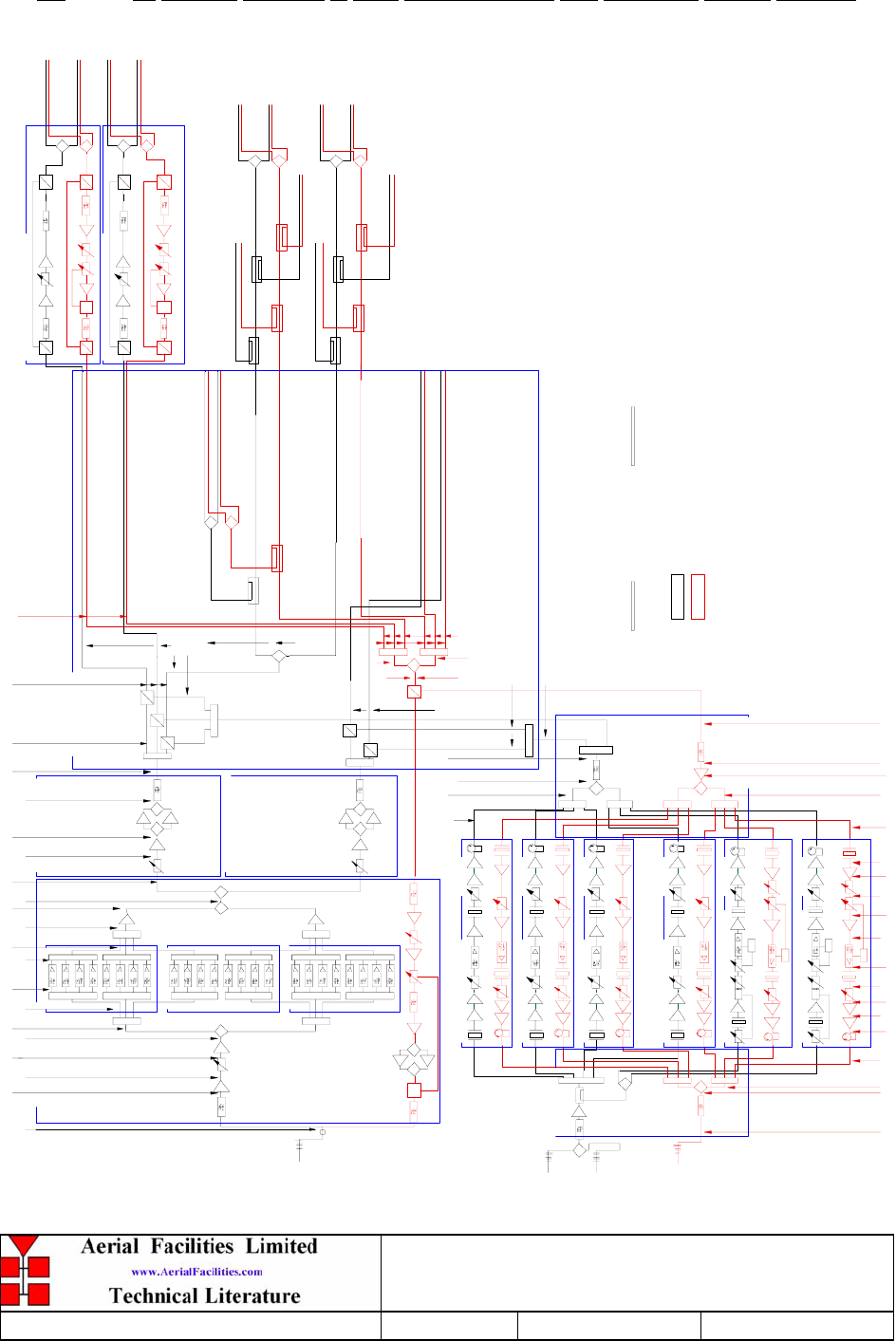
4. SYSTEM DRAWINGS
4.1 24 Channel 800MHz & VHF Simplex/Duplex Cell Enhancers System Diagram
0dB
0dB
0dB
0dB
0dB
0dB
0dB
0dB
17- 009127
17- 009127
17- 009127
17- 009127
17- 009127
17- 009127
17- 009127
17- 009127
0dB
0dB
0dB
0dB
0dB
0dB
0dB
0dB
17- 009127
17- 009127
17- 009127
17- 009127
17- 009127
17- 009127
17- 009127
0dB
0dB
0dB
0dB
0dB
0dB
0dB
0dB
17- 009127
17- 009127
17- 009127
17- 009127
17- 009127
17- 009127
17- 009127
dB
dB
dB
dBdB
ALC
DET
dBdB
ALC
DET
dB
dBdB
ALC
DET
dB
East Tunnel 'A'
East Tunnel 'B'
Space Antenna (Platform South Side)
S p ace An ten n a (P latfo r m No r th Sid e)
DOWNLINK
UPLINK
800M Hz OFF AIR REPEATER 800MHz HIGH POWER AMPL IF IER
800M Hz HIGH POWER AMPL IF IER
800M Hz T UNNEL IN LINE AM PL IF IER
800M Hz T UNNEL IN LINE AM PL IF IER
dB
0dB
dB
dB dB
VHF BI-DIRECT IONAL AM P
dB
0dB
dBdB
SQL
dB dB dB
VHF BI-DIRECTIONAL AMP(SIMPLEX)
0dB
SQL
dB dB dB
50-078002 50-078004
50-078004
VHF AIR INTERF ACE
50-078012
VHF COMBINER
50-078013
8 CHN M ODU L E 50-078003
8 CHN M ODU L E 50-078003
8 CHN M ODU L E 50-078003
50-078011
50-078010
-65d Bm
-66d Bm
-36d Bm
-52d Bm
-22d Bm
-25d Bm
-31d Bm
-37d Bm
-27d Bm
-33d Bm
-39d Bm
-19d Bm
-22d Bm
-25d Bm
-26d Bm
-12d Bm
18d Bm
17d Bm 12d Bm 11d Bm
Mission Valley
37d Bm
31d Bm
28d Bm
27d Bm
24d Bm
21d Bm
20d Bm
18d Bm
17d Bm
14d Bm
26d Bm 28d Bm
31d Bm 36.5d Bm 37d Bm -75d Bm-77d Bm
-57d Bm
-60d Bm
-66d Bm
-72d Bm
-51d Bm
-52d Bm
-55d Bm
-2d Bm
-22d Bm
-21d Bm -15d B m -35d Bm
-74d Bm
-71d Bm
-65d Bm
0dB
SQL
0dB
+24d B m +25d Bm +26d Bm -5d Bm -25d Bm -24d Bm -22d B m
-52d Bm
-51d Bm
-81d Bm -80d B m
-79d Bm
-71d Bm -65d Bm
-64d Bm
(+LONGDITUDE L OSS )
VHF LEVELS IN ITALICS
800M Hz L EV ELS NORMAL
Q110730
West M ezzan in e-DL
West M ezzan in e-UL
East M ezzan in e-DL
East M ezzan in e-UL
No r th M ezzan ine
Power Room (M238)
S tair s (P 104)
S tair s (P 103)
M ech an ical Ro o m
(M 204)
East M ech . (M 235)
West Tunnel 'A'
West Tunnel 'B'
UPLINK & DOWNL INK
DISTRIBUTION CABINET
6dB
6dB
6dB
6dB
6dB
6dB
Exit Stairs
Stair s 2 (P102)
Sto r e Ro o m (M 210)
S tair s (P 101)
Co r r id o r (M 211)
6dB
6dB
6dB
6dB
West Tunnel 'A'
F ir e Exit Stair 1
West Tunnel 'B'
F ir e Exit Stair 2
-90d Bm
-92d Bm
-82d Bm -90d Bm
-98d Bm
-77d Bm
-56d Bm
-57d Bm
-32d Bm
-11d Bm
-19d Bm
-20d Bm
0d Bm
37d Bm
dB
0dB
dB
dB dB
VHF BI-DIRE CT IONAL AM P 50-078011
0dB
dB
0dB
dB
dB dB
VHF BI-DIRE CT IONAL AM P 50-078011
0dB
dB
0dB
dB
dB dB
VHF BI-DIRE CT IONAL AM P 50-078011
0dB
dB
0dB
dBdB
SQL
VHF BI-DIRECTIONAL AMP(SIMPLEX) 50-078010
dB
dB
800MHz & VHF Cell Enhancers
Maintenance Handbook
H/book Number:-50-078001HBKM Issue No:-A Date:-02/09/2004 Page:-48 of 88
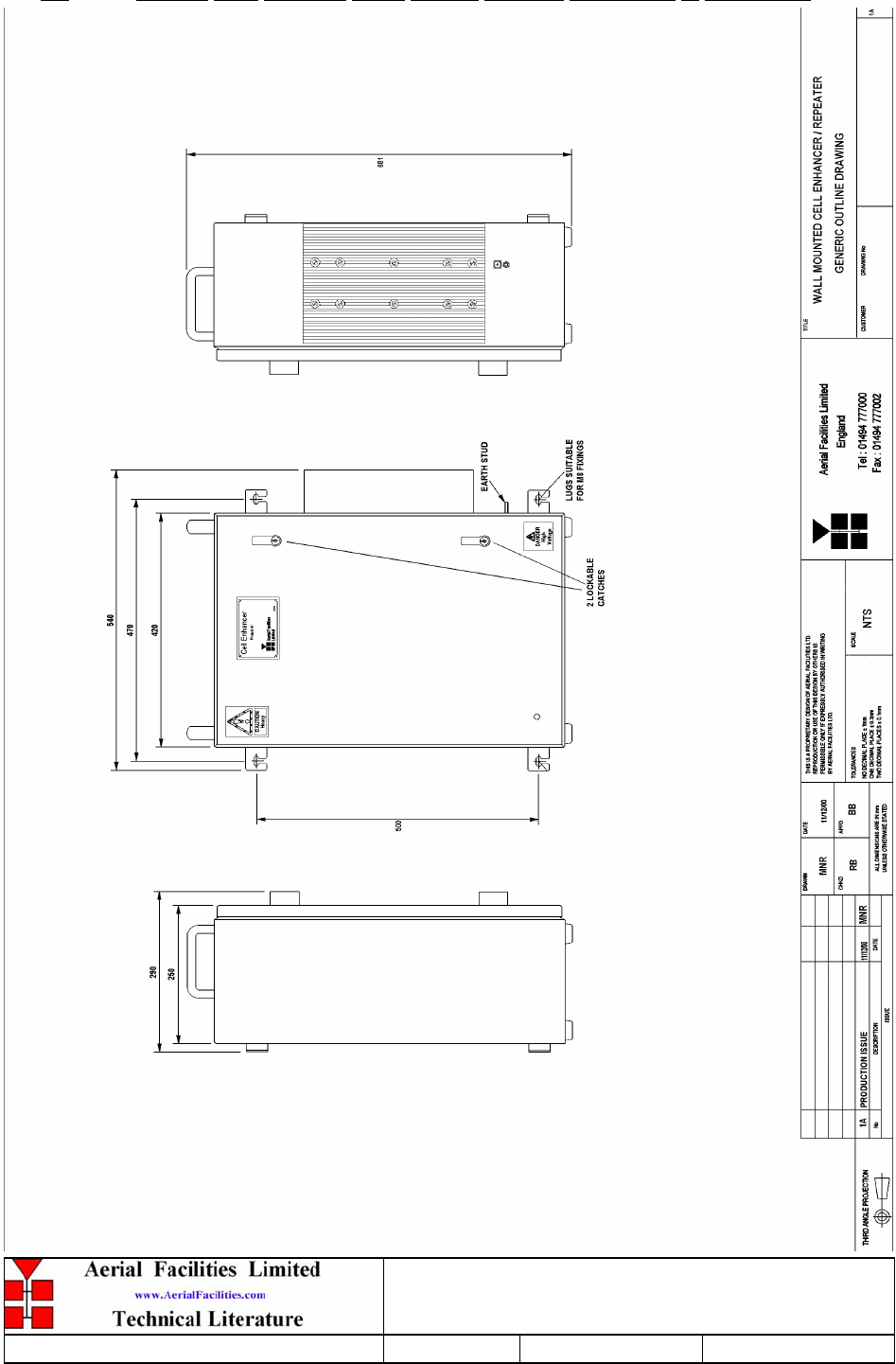
4.2 Generic Wall Mounted Cases Outline Drawing (50-078017 & 80-209302)
800MHz & VHF Cell Enhancers
Maintenance Handbook
H/book Number:-50-078001HBKM Issue No:-A Date:-02/09/2004 Page:-49 of 88
5. SUB-UNIT MODULES
5.1 Bandpass Filters (02-007201 & 01-002503)
5.1.1 Description
The bandpass filters are multi-section designs with a bandwidth dependent upon the
passband frequencies, (both tuned to customer requirements). The response shape is
basically Chebyshev with a passband design ripple of 0.1dB. The filters are of slot coupled,
folded combline design, and are carefully aligned during manufacture in order to optimise
the insertion loss, VSWR and intermodulation characteristics of the unit. The tuned elements
are silver-plated to reduce surface ohmic losses and maintain a good VSWR figure and 50
load at the input and output ports.
Being passive devices, the bandpass filters should have an extremely long operational life
and require no maintenance. Should a filter be suspect, it is usually most time efficient to
replace the module rather than attempt repair or re-tuning.
5.1.2 Technical Specification (02-007201)
PARAMETER SPECIFICATION
Response Type Chebyshev
Frequency Range: 800 - 950MHz (tuned to spec.)
Bandwidth: 10-25MHz (tuned to spec.)
Number of Sections: 8
Insertion Loss: 1.0 dB
VSWR: better than 1.2:1
Power Handling: 100W max
operation: -10°C to +60°C Temperature
range: storage: -20°C to +70°C
Weight: 3 kg (typical)
5.1.3 Technical Specification (01-002503)
SPECIFICATION PARAMETER
Response type: Chebyshev
Frequency range: 135 – 250MHz
Bandwidth: 3.5MHz (tuned to spec.)
N. of sections: 6
Insertion loss: 1.2dB
VSWR: Better than 1.2:1
Power Handling: 100W maximum
operate: -10°C to +60°C
Temperature range: store: -20°C to +70°C
Weight: 3 kg
Size: 384 x 82.5 x 56.4mm
800MHz & VHF Cell Enhancers
Maintenance Handbook
H/book Number:-50-078001HBKM Issue No:-A Date:-02/09/2004 Page:-50 of 88
5.2 900MHz Splitter/Combiner (05-002602)
5.2.1 Description
The Splitter/Combiner used is a device for accurately matching two or more RF signals to
single or multiple ports, whilst maintaining an accurate 50Ω load to all inputs/outputs and
ensuring that the VSWR and insertion losses are kept to a minimum. Any unused ports will
be terminated with an appropriate 50Ω load.
Being passive devices, the splitters should have an extremely long operational life and
require no maintenance. Should a unit be suspect, it is usually most time efficient to replace
the whole module rather than attempt repair or re-tuning.
Being passive devices, the splitters should have an extremely long operational life and
require no maintenance. Should a unit be suspect, it is usually most time efficient to replace
the whole module rather than attempt repair or re-tuning.
5.2.2 Technical Specification
PARAMETER SPECIFICATION
Narrowband: 815 – 960MHz Frequency
Range: Broadband: 800 – 1200MHz
Narrowband: 145MHz
Bandwidth: Broadband: 400MHz
Input ports: 1
Output ports: 2
Narrowband: 3.3dB
Insertion loss: Broadband: 3.5dB
Return loss input & output: 1.3:1
Impedance: 50
Narrowband: >20dB
Isolation: Broadband: >18dB
MTFB: >180,000 hours
Splitting: 20Watts
Power rating: Combining: 0.5Watt
Connectors: SMA female
Weight: 200g (approximately)
Size: 54 x 44 x 21mm (including
connectors)
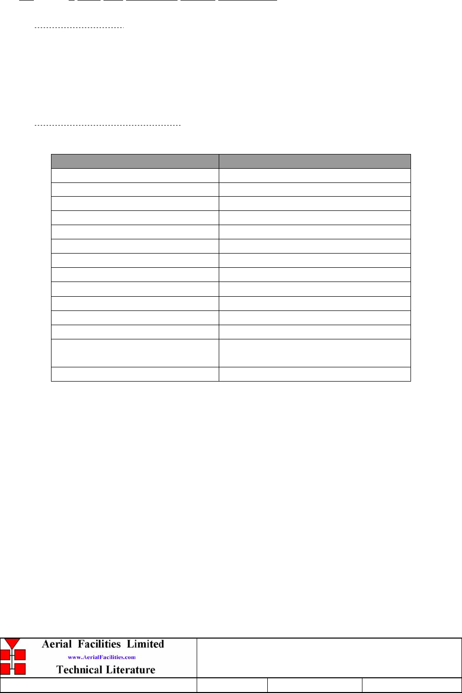
800MHz & VHF Cell Enhancers
Maintenance Handbook
H/book Number:-50-078001HBKM Issue No:-A Date:-02/09/2004 Page:-51 of 88
5.3 1 Watt 3dB Broadband Splitter (05-002901)
5.3.1 Description
The 1 Watt, 3dB Splitter/Combiner used is a device for accurately matching two or more RF
signals to single or multiple ports, whilst maintaining an accurate 50Ω load to all
inputs/outputs and ensuring that the VSWR and insertion losses are kept to a minimum. Any
unused ports will be terminated with an appropriate 50Ω load.
5.3.2 Technical Specification
PARAMETER SPECIFICATION
Frequency Range: 100 - 520 MHz
Bandwidth: 380 MHz
Inputs: 1
Outputs: 2
Insertion Loss: 3.5 dB (typical)
Isolation: >18 dB
Return Loss (VSWR) – Input: Better than 1.3:1
Return Loss (VSWR) – Output: Better than 1.3:1
Impedance: 50 Ω
Power Rating – Splitter: 20 Watts
Power Rating – Combiner: 1.0 Watt
Connectors: SMA female
Size: 54 x 44 x 21 mm (including
connectors)
Weight: 200 gm (approximately)
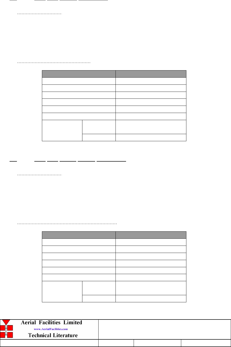
800MHz & VHF Cell Enhancers
Maintenance Handbook
H/book Number:-50-078001HBKM Issue No:-A Date:-02/09/2004 Page:-52 of 88
5.4 Four Way Splitter (05-003302)
5.4.1 Description
The Splitter/Combiner used is a device for accurately matching two or more RF signals to
single or multiple ports, whilst maintaining an accurate 50Ω load to all inputs/outputs and
ensuring that the VSWR and insertion losses are kept to a minimum. Any unused ports
will be terminated with an appropriate 50Ω load.
5.4.2 Technical Specification
PARAMETER SPECIFICATION
Frequency range: 700-900MHz
Bandwidth: 200MHz
Rejection: >14dB
Insertion loss: 7.5dB (in band, typical)
Connectors: SMA
Weight: <1.5kg
operational
:
-10°C to +60°C
Temperature
range: storage -20°C to +70°C
5.5 Four Way Hybrid Splitter (05-003401)
5.5.1 Description
The hybrid splitter used is a device for accurately matching one or more RF signals to
single or multiple ports, whilst maintaining an accurate 50Ω load to all inputs/outputs and
ensuring that the VSWR and insertion losses are kept to a minimum. Any unused ports
would be terminated with an appropriate 50Ω load.
5.5.2 Technical Specification 05-003401
PARAMETER SPECIFICATION
Frequency range: 70 – 250MHz
Bandwidth: 180MHz
Rejection: >14dB
Insertion loss: 6.5dB (in band, typical)
Connectors: SMA
Weight: <1.5kg
operational
:
-10°C to +60°C
Temperature
range: storage -20°C to +70°C
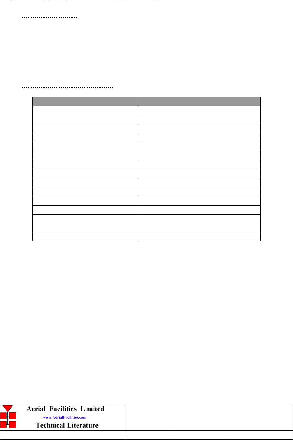
800MHz & VHF Cell Enhancers
Maintenance Handbook
H/book Number:-50-078001HBKM Issue No:-A Date:-02/09/2004 Page:-53 of 88
5.6 3 Way Splitter/Combiner (05-003801)
5.6.1 Description
The 3 way Splitter/Combiner used is a ‘Zinger’ type design for accurately matching three
RF signals to a single port, whilst maintaining an accurate balance between ports, and
ensuring that the VSWR and insertion losses attain the best possible specification. They are
specialist passive devices and must be replaced in the unlikely event of failure.
5.6.2 Technical Specification
PARAMETER SPECIFICATION
Frequency Range: 800-1000MHz
Bandwidth: 200MHz (typical)
Inputs: 3
Outputs: 1
Insertion Loss: 5.2 dB (typical)
Isolation: >18 dB
Return Loss (VSWR) – Input: Better than 1.35:1
Return Loss (VSWR) – Output: Better than 1.35:1
Impedance: 50 Ω
Power Rating – Splitter: 20 Watts
Power Rating – Combiner: 0.5 Watt
Connectors: SMA female
Size: 54 x 44 x 21 mm (including
connectors)
Weight: 200 gm (approximately)
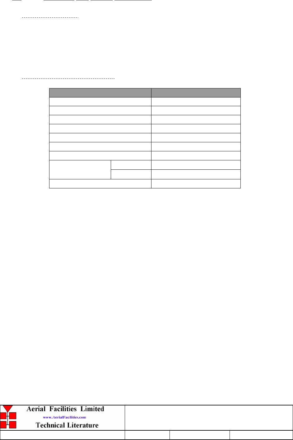
800MHz & VHF Cell Enhancers
Maintenance Handbook
H/book Number:-50-078001HBKM Issue No:-A Date:-02/09/2004 Page:-54 of 88
5.7 Wideband 3dB Splitter (07-004101)
5.7.1 Description
This wideband, 2 way hybrid splitter, is an AFL stock item with many years of
reliable service. The successful construction of such a device, relies largely on a pcb
developed within a rigid specification, skilled assembly and testing. Insertion loss
quoted is a typical figure, any unit will be within 5% of this figure.
5.7.2 Technical Specification
PARAMETER SPECIFICATION
Frequency Range: 70-1000MHz
Split ratio: 1:2
Insertion Loss: 3.2dB (typical)
Isolation: >20dB
Power rating: 1.0 Watt
VSWR: Better than 1.3:1
Available connectors: BNC, N type, SMA
operation: -10°C to +60°C Temperature
range: storage: -20°C to +70°C
Weight: Circa 200gms

800MHz & VHF Cell Enhancers
Maintenance Handbook
H/book Number:-50-078001HBKM Issue No:-A Date:-02/09/2004 Page:-55 of 88
5.8 VHF/UHF 3-Way Splitter (07-005401)
5.8.1 Description
The 3dB Splitter/Combiner used is a device for accurately matching two or more RF signals
to single or multiple ports, whilst maintaining an accurate 50Ω load to all inputs/outputs and
ensuring that the VSWR and insertion losses are kept to a minimum. Any unused ports will
be terminated with an appropriate 50Ω load.
5.8.2 Technical Specification
PARAMETER SPECIFICATION
Frequency Range: 160-470MHz
Bandwidth: 300MHz
Inputs: 1
Outputs: 3
Insertion Loss: 4.5 dB (typical)
Isolation: >14 dB
Return Loss (VSWR) – Input: Better than 1.3:1
Return Loss (VSWR) – Output: Better than 1.3:1
Impedance: 50 Ω
Power Rating – Splitter: 20 Watts
Power Rating – Combiner: 0.5 Watt
Connectors: SMA female
Size: 54 x 44 x 21 mm (including
connectors)
Weight: 200 gm (approximately)
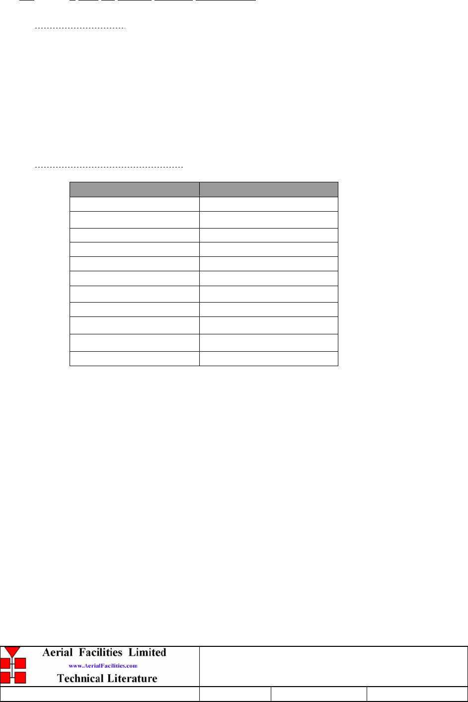
800MHz & VHF Cell Enhancers
Maintenance Handbook
H/book Number:-50-078001HBKM Issue No:-A Date:-02/09/2004 Page:-56 of 88
5.9 3 Port Tx Hybrid Coupler (80-024203)
5.9.1 Description
The transmitter hybrid couplers provide isolation from unwanted reflected frequencies
to/from the leaky feeder antennas. They are specialist narrow-band 3 port devices, designed
with rejection and power handling as the main criteria. Being passive devices, the hybrid
couplers should be maintenance free over their entire lifetime and have an extremely high
MTBF figure. It is not recommended that the top cover be removed or any of the internal
components needlessly touched, since the original factory alignment/tuning would be
extremely hard to reproduce in a ‘field’ environment.
5.9.2 Technical Specification
PARAMETER SPECIFICATION
Frequency Range: 140-175 MHz
Bandwidth: ±10% of fo
Insertion Loss: 3.5dB
Rejection: -18dB
Impedance: 50
V.S.W.R: 1.2:1
Input to input isolation: >20dB
Connectors: Type N Standard
Dimensions: 140 x 120 x 35mm
Power rating: 50Watts
Weight: 0.5kg
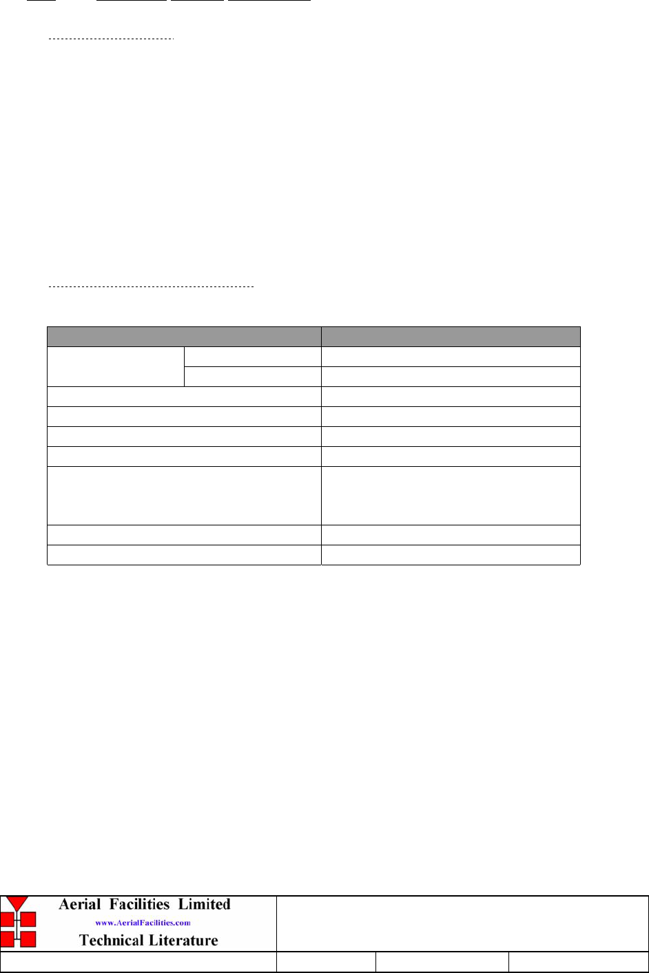
800MHz & VHF Cell Enhancers
Maintenance Handbook
H/book Number:-50-078001HBKM Issue No:-A Date:-02/09/2004 Page:-57 of 88
5.10 Crossband Coupler (07-005705)
5.10.1 Description
The purpose of a crossband coupler is to either combine/split transmission signals from
different parts of the frequency spectrum.
The crossband coupler fitted here, is the means by which the separate VHF and UHF
frequency band signals are mixed to form a composite RF signal.
It basically comprises of a 3 port device, two filters, one a low pass the other a high pass,
that are then mixed and fed to a common output. The couplers are built into a machined
aluminium casing having a centre screening wall between the filter sections and lid secured
by screws at frequent intervals over its perimeter to obtain a tight seal and to ensure linearity
and stability of response.
5.10.2 Technical Specification
PARAMETER SPECIFICATION
250MHz: 70-250MHz
Passband 380MHz: 380-960MHz
Power Rating: 50 Watts (CW)
Number of Input ports: 2
Number of Output ports: 1
Insertion loss: 0.5 dB
Isolation:
> 50 dB 70-250MHz
> 50 dB 380-960MHz
(15 dB typical return loss 500-960)
Impedance: 50
Connectors: SMA- female
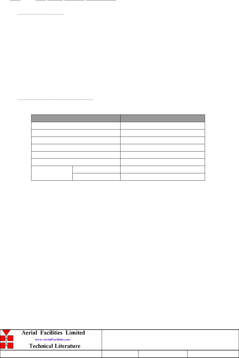
800MHz & VHF Cell Enhancers
Maintenance Handbook
H/book Number:-50-078001HBKM Issue No:-A Date:-02/09/2004 Page:-58 of 88
5.11 6dB Power Monitor (07-014002)
5.11.1 Description
The purpose of these couplers is to tap off known portions (usually 3-30dB) of RF signal
from transmission lines, either resistively or by induction, and to combine them, for
example through splitter units for different purposes (alarms/monitoring etc.), whilst
maintaining an accurate 50Ω load to all ports/interfaces throughout the specified frequency
range. They are formally known as directional couplers as they couple power from the RF
mainline in one direction only.
Various constructional techniques are used depending on the specification required. These
include microstrip, stripline, coaxial cable and capacitive types.
5.11.2 Technical Specification
PARAMETER SPECIFICATION
Frequency range: 170 – 2200MHz
Insertion Loss: <0.3dB
Coupling level: -6dB
Rejection: N/A
Weight: <200gms
Connectors: N type, female
operation: -10°C to +60°C Temperature
range: storage: -20°C to +70°C
800MHz & VHF Cell Enhancers
Maintenance Handbook
H/book Number:-50-078001HBKM Issue No:-A Date:-02/09/2004 Page:-59 of 88
5.12 2-Port RF Isolator (08-930002)
5.12.1 Description
The purpose of fitting an isolator to the output of a transmitter in a multi-transmitter
environment is such that each output is afforded a degree of isolation from every other. Were
this not to be the case, two simultaneous transmissions could interfere to create
intermodulation products, especially in the non-linear power amplifier output stages of the
transmitters. Whilst this effect would not affect the intelligibility of the two original
transmissions, a further two new transmissions would be created which could themselves
cause interference to third party users.
The ferrite isolator is a ferro-magnetic device, which has directional properties. In the
forward direction, RF arriving at the input is passed to the output with minimal attenuation.
In the reverse direction, RF arriving at the output due to reflected power from a badly
matched load, or due to coupling with another transmitter, is routed into an RF load where it
is absorbed. The isolator therefore functions to prevent reflected RF energy reaching the
power amplifier where it could cause intermodulation products or premature device failure.
5.12.2 Technical Specification
PARAMETER SPECIFICATION
Frequency range: 150-300MHz
Bandwidth (% of centre frequency): 2
Isolation: 35dB (typical)
Insertion loss: 0.25dB (typical
V.S.W.R: 1.15:1 (typical)
Maximum power: 200Watts (per carrier)
Connector: SMA
Weight: 200gm (approximately)

800MHz & VHF Cell Enhancers
Maintenance Handbook
H/book Number:-50-078001HBKM Issue No:-A Date:-02/09/2004 Page:-60 of 88
5.13 ¼Watt 0- -30dB & 0-15dB Variable Attenuators (10-000701 & 10-000901)
5.13.1 General Application
In many practical applications for Cell Enhancers etc., the gain in each path is found to be
excessive. Therefore, provision is made within the unit for the setting of attenuation in
each path, to reduce the gain.
5.13.2 Switched Attenuators
The AFL switched attenuators are available in two different types; 0 – 30dB in 2 dB
steps, or 0 – 15dB in 1 dB steps. The attenuation is simply set using the four miniature
toggle switches on the top of each unit. Each switch is clearly marked with the
attenuation it provides, and the total attenuation in line is the sum of the values switched
in. They are designed to maintain an accurate 50 impedance over their operating
frequency at both input and output.
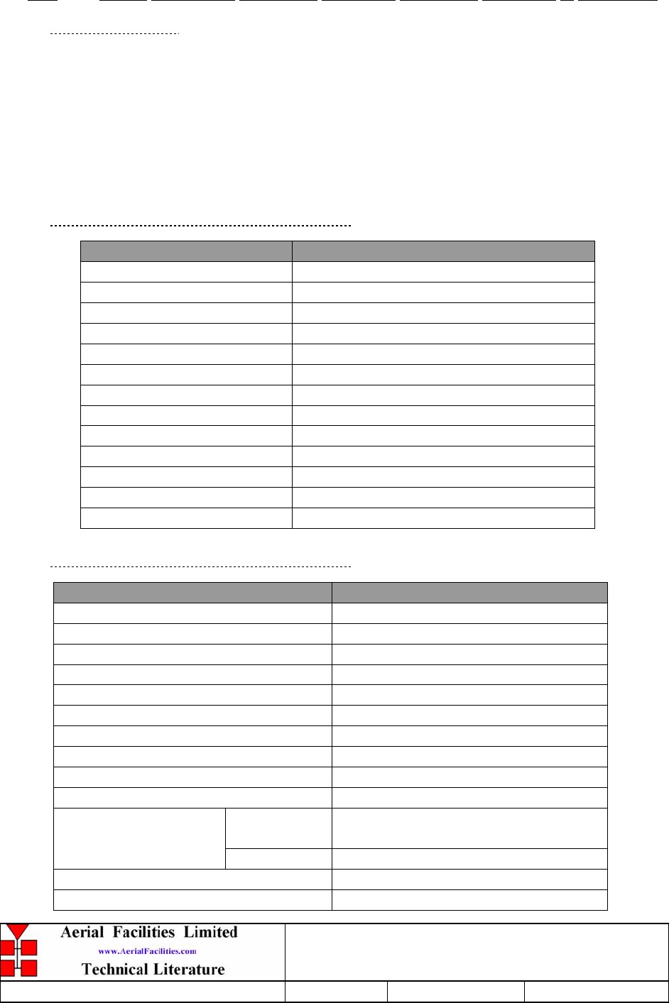
800MHz & VHF Cell Enhancers
Maintenance Handbook
H/book Number:-50-078001HBKM Issue No:-A Date:-02/09/2004 Page:-61 of 88
5.14 LNA’s (11-001202, 11-005802, 11-005902 11-006002, 11-006702 & 11-004802)
5.14.1 Description
The Gallium-Arsenide low noise amplifiers used in the unit are double stage, solid-state low
noise amplifiers. Class A circuitry is used throughout the units to ensure excellent linearity
and extremely low noise over a very wide dynamic range. The active devices are very
moderately rated to provide a long trouble-free working life. There are no adjustments on
these amplifiers, and in the unlikely event of a failure, then the complete amplifier should be
replaced. This amplifier features its own in-built alarm system which gives a volt-free relay
contact type alarm that is easily integrated into the main alarm system.
5.14.2 Technical Specification (11-001202)
PARAMETER SPECIFICATION
Frequency range: 10 - 600MHz
Bandwidth: 200MHz (as required, tuneable)
1dB Compression point: >+15 dBm
3rd order intercept: >+25dBm
Gain: 20dB (typical)
VSWR: better than 1.5:1
Noise figure: 3.5dB (typical)
Connectors: SMA female
Supply: 108mA @ 24V DC
Temp. range: operational: -10°C to +60°C
storage: -20°C to +70°C
Weight: 0.4kg
Size: 88.9 x 50.8 x 31.75 mm (case only)
5.14.3 Technical Specification (11-004802)
PARAMETER SPECIFICATION
Frequency Range: 350 - 550MHz
Bandwidth: <100MHz (as required, tuneable)
1dB Compression Point: >+29dBm
3rd Order Intercept: >+44dBm
Gain: >10dB (typical)
VSWR: better than 1.5:1
Input return loss: >14dB
Noise Figure: <4.0dB (typical)
Connectors: SMA female
Supply: 300mA at 24V DC
operational
:
-10°C to +60°C
Temperature range:
storage: -20°C to +70°C
Size: 88 x 50 x 34mm (ex. connectors)
Weight: 0.26kg
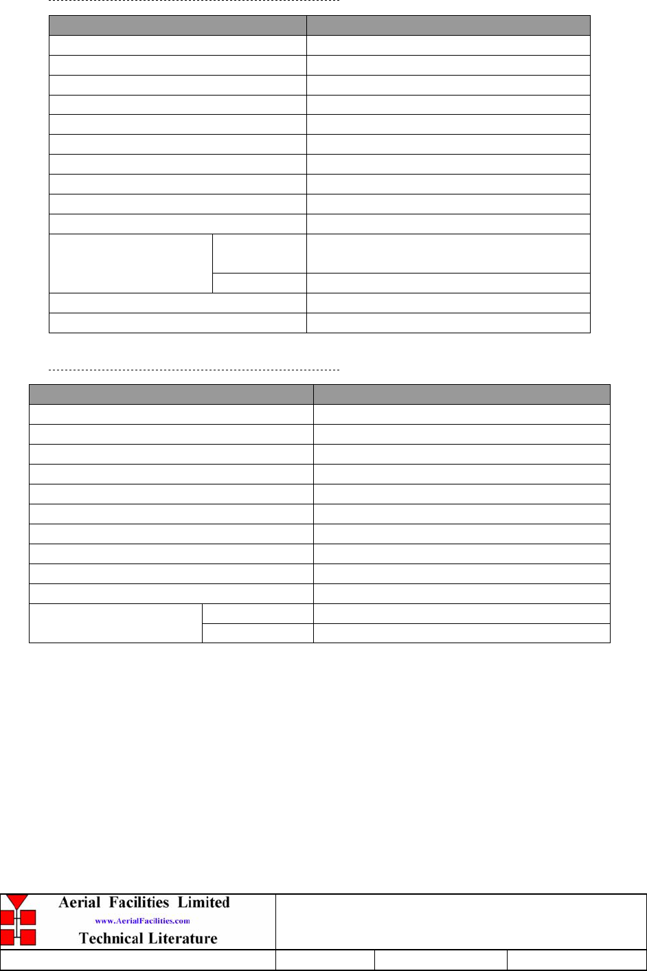
800MHz & VHF Cell Enhancers
Maintenance Handbook
H/book Number:-50-078001HBKM Issue No:-A Date:-02/09/2004 Page:-62 of 88
5.14.4 Technical Specification (11-005802)
PARAMETER SPECIFICATION
Frequency Range: 800 – 960MHz
Bandwidth: <170MHz
Gain: 14.5±0.5dB (typical)
1dB Compression Point: 30dBm
OIP3: 46dBm
Input/Output Return Loss: >18dB
Noise Figure: <2.7dB
Power Consumption: 510-540mA @ 24V DC
Supply Voltage: 10-24V DC
Connectors: SMA female
operational
:
-10°C to +55°C
Temperature Range:
storage: -40°C to +70°C
Size: 90 x 55 x 30.2mm
Weight: 280gm (approximately)
5.14.5 Technical Specification (11-005902)
PARAMETER SPECIFICATION
Frequency Range: 800 – 960MHz
Bandwidth: <170MHz
Gain: 19.5dB (typical)
1dB Compression Point: 21dBm
OIP3: 33dBm
Input/Output Return Loss: >20dB
Noise Figure: 1dB (typical)
Power Consumption: 190mA @ 24V DC
Supply Voltage: 10-24V DC
Connectors: SMA female
operational: -10°C to +55°C
Temperature Range: storage: -40°C to +70°C
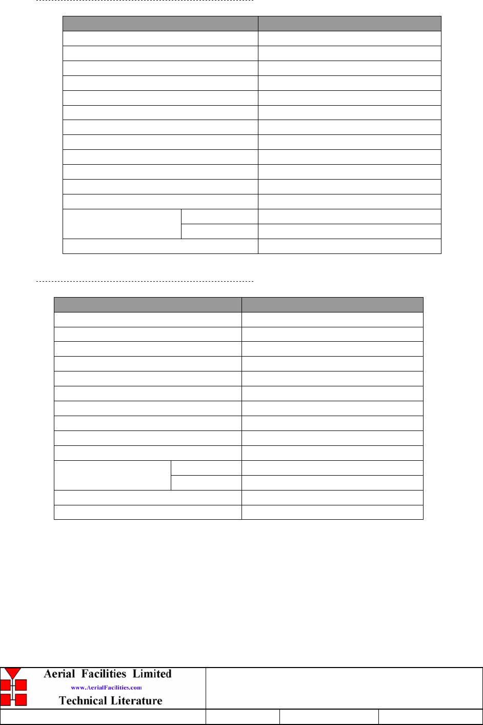
800MHz & VHF Cell Enhancers
Maintenance Handbook
H/book Number:-50-078001HBKM Issue No:-A Date:-02/09/2004 Page:-63 of 88
5.14.6 Technical Specification (11-006002)
PARAMETER SPECIFICATION
Frequency range: 70 – 500MHz
Bandwidth: <430MHz
Gain: 21dB (typical)
1dB Compression Point: +20dB (typical)
3rd order intercept: +33dB (typical)
Input return loss: >14dB
Output return loss: >20dB
VSWR: Better than 1.5:1
Noise figure: <2.7dB
Connectors: SMA female
Supply: 230 - 260mA @ 10 to 24V DC
Size: 88 x 50 x 34mm (ex. connectors)
operational: -10°C to +60°C
Temperature range: storage: -20°C to +70°C
Weight: 0.26kg
5.14.7 Technical Specification (11-006702)
PARAMETER SPECIFICATION
Frequency Range: 800 – 1000MHz
Bandwidth: <200MHz
Gain: 29dB (typical)
1dB Compression Point: 20dBm
OIP3: 33dBm
Input/Output Return Loss: >18dB
Noise Figure: 1.3dB (typical)
Power Consumption: 180mA @ 24V DC
Supply Voltage: 10-24V DC
Connectors: SMA female
operational: -10°C to +55°C
Temperature Range: storage: -40°C to +70°C
Size: 90 x 55 x 30.2mm
Weight: 290gms (approximately)
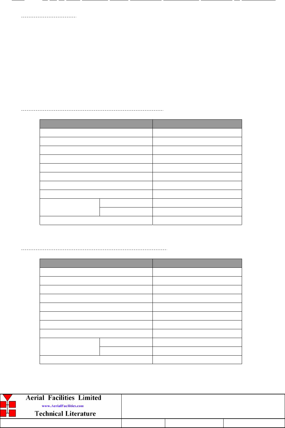
800MHz & VHF Cell Enhancers
Maintenance Handbook
H/book Number:-50-078001HBKM Issue No:-A Date:-02/09/2004 Page:-64 of 88
5.15 5, 10 & 20W 900MHz Power Amplifiers (12-018601, 12-018001 & 12-018002)
5.15.1 Description
These Gallium-Arsenide power amplifiers are Class A 10 & 20W power amplifier from
800-960MHz in a 1 stage balanced configuration. It demonstrates a very high linearity
and a very good input/output return loss. It has built in a Current Fault Alarm Function
with a volt-free relay contact pair as its output.
Its housing is an aluminium case (Alocrom 1200 finish) with SMA connectors for the RF
input/output and a D-Type connector for the power supply and the Current Fault Alarm
Function. These amplifiers have no user adjustments and in case of failure should only be
replaced.
5.15.2 Technical Specification (12-018601, 5W)
PARAMETER SPECIFICATION
Frequency range: 800-960MHz
Small signal gain: 30dB
Gain flatness: ±1.2dB
I/O Return loss: >20dB
1dB compression point: 37dBm
OIP3: 52dBm
Supply voltage: 12V DC
Supply current: 2.0Amps (Typical)
operational: -10°C to +55°C Temperature
range storage: -30°C to +70°C
Weight: <2kg (no heatsink)
5.15.3 Technical Specification (12-018001, 10W)
PARAMETER SPECIFICATION
Frequency range: 800-960MHz
Small signal gain: 30dB
Gain flatness: ±1.2dB
I/O Return loss: >18dB
1dB compression point: 42.8dBm
OIP3: 56dBm
Supply voltage: 24V DC
Supply current: 5.0Amps (Typical)
operational: -10°C to +55°C Temperature
range storage: -30°C to +70°C
Weight: <2kg (no heatsink)
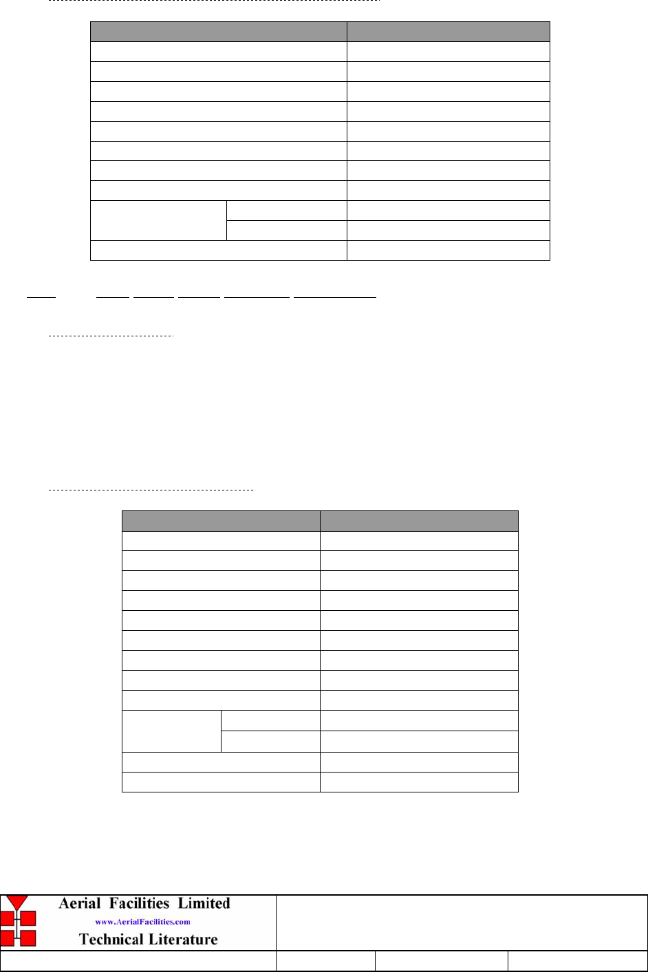
800MHz & VHF Cell Enhancers
Maintenance Handbook
H/book Number:-50-078001HBKM Issue No:-A Date:-02/09/2004 Page:-65 of 88
5.15.4 Technical Specification (12-018002, 20W)
PARAMETER SPECIFICATION
Frequency range: 800-960MHz
Small signal gain: 30dB
Gain flatness: ±1.2dB
I/O Return loss: >18dB
1dB compression point: 42.8dBm
OIP3: 56dBm
Supply voltage: 12V DC
Supply current: 5.0Amps (Typical)
operational: -10°C to +55°C Temperature
range storage: -30°C to +70°C
Weight: <2kg (no heatsink)
5.16 VHF 5Watt Power Amplifier (12-004902)
5.16.1 Description
The power amplifier used is a triple stage solid-state low-noise amplifier. Class AB circuitry
is used in the unit to ensure good linearity over a wide dynamic range. The three active
devices are very moderately rated to provide a long trouble-free working life. There are no
adjustments on this amplifier, and in the unlikely event of failure then the entire amplifier
should be replaced.
5.16.2 Technical Specification
PARAMETER SPECIFICATION
Frequency range: 80-260MHz
Bandwidth: 20MHz (tuned to specificati
o
Maximum RF output: >5.0 Watt
Gain: 40dB
1dB compression point: +30dBm
3rd order intercept point: +40dBm
VSWR: better than 1.5:1
Connectors: SMA female
Supply: 2000mA @ 24V DC
operational: -10°C to +60°C
Temperature
range: storage: -20°C to +70°C
Weight: 0.5 kg
Size: 167x52x25mm

800MHz & VHF Cell Enhancers
Maintenance Handbook
H/book Number:-50-078001HBKM Issue No:-A Date:-02/09/2004 Page:-66 of 88
5.17 3 Stage Alarm PCB & 3 Stage Simplex Alarm PCB(12-002201 & 12-002203)
5.17.1 Description
Amplifier Alarm Boards are fitted to monitor the bias conditions of AFL Class A
amplifiers which remain constant in normal operation. Any departure from normal bias
conditions is a result of device failure, excess temperature, over-driving or oscillation
(excessive power).
In normal operation, the Class A bias circuit of the amplifier develops a constant voltage of
1.20V across the collector current setting resistor. The Amplifier Alarm Board is a window
comparator device, which is adjusted to sense a departure from this condition. Several
different alarm outputs are provided to simplify interfacing, (Relay Contact, Open
Collector, and TTL Logic Levels)
The basic version of the Alarm Board (12-002801) monitors a single amplifier stage. A
three-stage version (12-002201) is used on complex amplifiers where three separate
comparators have their outputs logically combined to a common output stage. Failure of
any one stage will activate the alarms.
Note that the alarm board has a green Light Emitting Diode located near to the centre of the
printed circuit board, which is illuminated on ‘Good’, and extinguished on ‘Alarm’. It is
therefore a simple matter to identify an active module failure, by searching for an Alarm
Board which has its green LED extinguished. A simple test of the alarm board is possible
by shorting across the monitor inputs, pins 1 and 2, 3 and 4 or across pins 5 and 6. This last
monitor input is inactive if the board has been converted to a two way alarm board. (Refer
to relevant amplifier alarm wiring diagram.)
1) Volt-free change over relay contacts.
2) Open collector NPN transistor pulls low on alarm.
3) TTL driver.
In systems using simplex channel switching, it is necessary to be able to distinguish
between a ‘normal’ switching operation and erroneous modes where faults in the detector
circuitry may cause data errors but not necessarily fire the alarms. The simplex alarm
board is designed to differentiate between normal and spurious switching signals
There are two selectable link options on the three-way board:
LINK1 - Removed to convert to two-way alarm board.
LINK2 - Removed to isolate 0V from chassis earth.
The one way alarm board only has the 0V isolation link (LINK2) fitted.
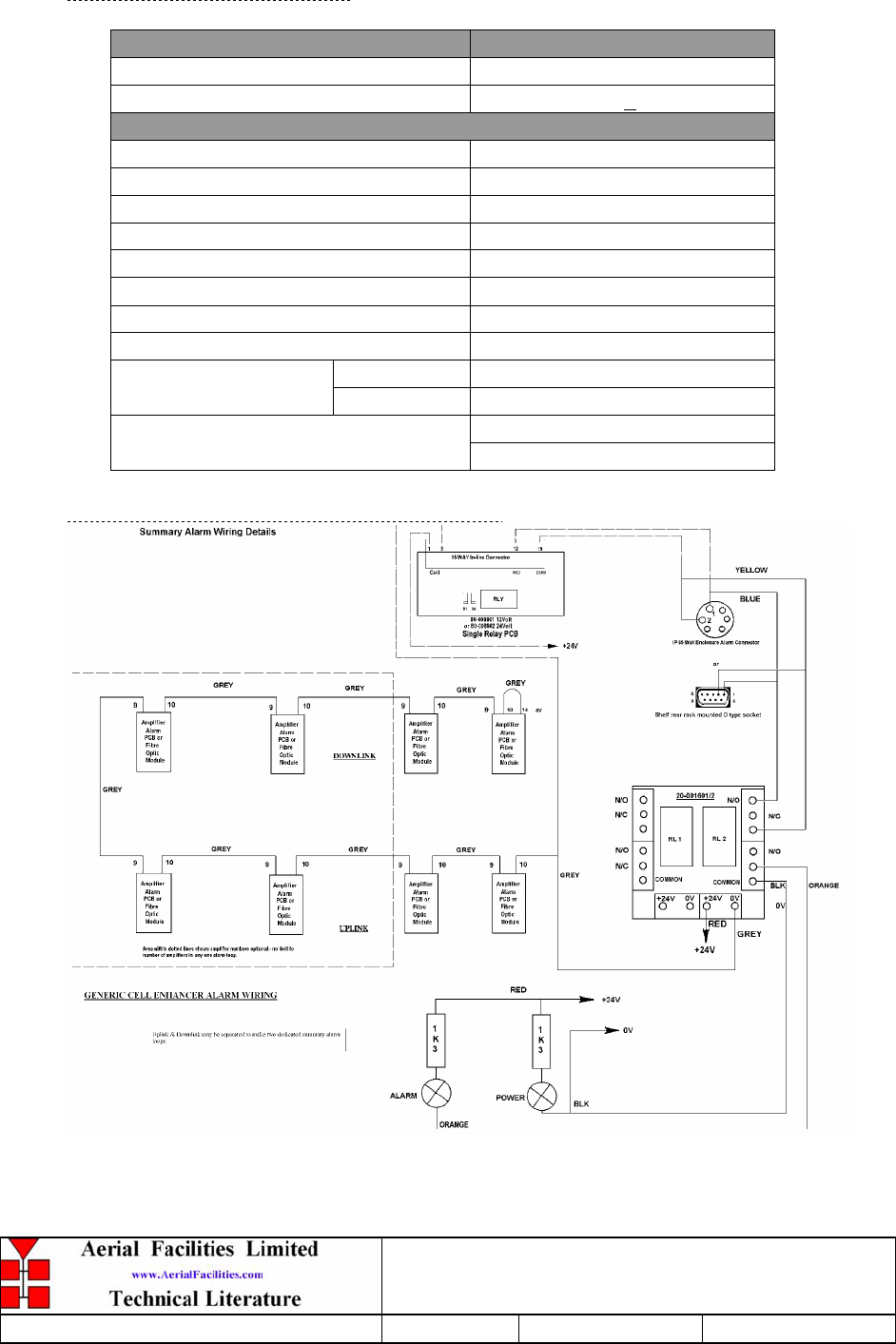
800MHz & VHF Cell Enhancers
Maintenance Handbook
H/book Number:-50-078001HBKM Issue No:-A Date:-02/09/2004 Page:-67 of 88
5.17.2 Technical Specification
PARAMETER SPECIFICATION
Operating voltage: 8 to 30V (floating earth)
Alarm Threshold: Vcc - 1.20 volt +15%
Alarm output relay contacts:
Max. switch current: 1.0Amp
Max. switch volts: 120Vdc/60VA
Max. switch power: 24W/60VA
Min. switch load: 10.0µA/10.0mV
Relay isolation: 1.5kV
Mechanical life: >2x10⁷ operations
Relay approval: BT type 56
Connector details: 15-way 0.1" pitch
operational: -10°C to +60°C
Temperature range: storage: -20°C to +70°C
74 x 56mm (3 stage)
PCB Size: 54 x 56mm (1 stage)
5.17.3 Generic Summary Alarm Wiring Sketch

800MHz & VHF Cell Enhancers
Maintenance Handbook
H/book Number:-50-078001HBKM Issue No:-A Date:-02/09/2004 Page:-68 of 88
5.18 1 & 3 Stage Alarm/Simplex/Mute PCB (12-002804 & 12-002213)
5.18.1 Description
In systems using simplex channel switching, it is necessary to be able to distinguish
between a ‘normal’ switching operation and erroneous modes where faults in the detector
circuitry may cause data errors but not necessarily fire the alarms. The simplex
alarm/mute board is designed to differentiate between normal and spurious switching
signals for single or multiple stage amplifiers.
5.19 Simplex Controller PCB (12-002811)
5.19.1 Description
The Simplex controller logic PCB monitors the receiver squelch output for a signal change
and activates the supply switching for either the uplink or down link path accordingly. In
normal operation, the low level Rx path is activated, and the associated Tx path is switched
off. When a signal is detected by the Rx Squelch module, the Rx squelch output goes low
(0v), which triggers the controller logic PCB. The PCB mutes the power supply to the
opposite path Rx LNA’s and switches on the power to the output power stage. In order to
prevent the power stage noise blocking the opposite path’s low level receiver, the power
amplifier is normally muted.
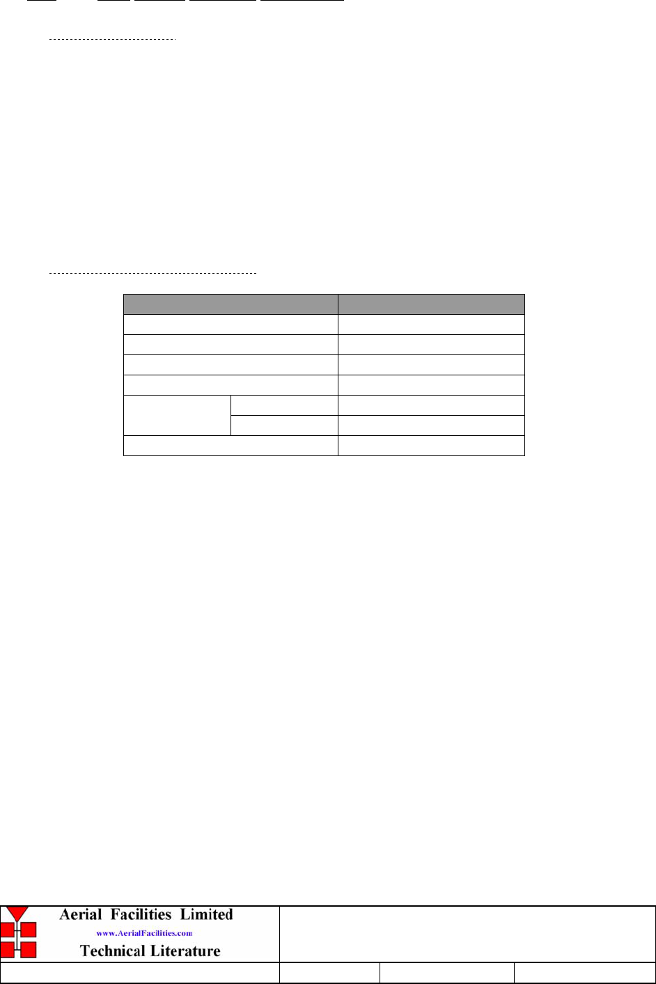
800MHz & VHF Cell Enhancers
Maintenance Handbook
H/book Number:-50-078001HBKM Issue No:-A Date:-02/09/2004 Page:-69 of 88
5.20 Dual DC/DC Converter (13-001803)
5.20.1 Description
This unit is employed where it is necessary to derive two fixed voltage power supply rails
from some higher voltage. Typically it is used to derive 5, 8, 12 or 15V from a 24V input.
The circuit is based upon a pair of LM257 series variable voltage regulators (LM2576, 12 &
15V & LM2575, 5V), which are each capable of supplying an absolute maximum of 1.5A
output current. Note that at full output current, the dissipation of the device must remain
within design limits, bearing in mind the voltage which is being dropped across it. The
maximum allowable dissipation will also depend on the efficiency of the heatsink on which
the device is mounted.
5.20.1 Technical Specification
PARAMETER SPECIFICATION
Operating Voltage: 21 – 27V DC
Output Voltage: 12V & 12V (typical)
Output Current: 1.0A (maximum per o/p)
Connections: Screw Terminal Block
operational: -10°C to +60°C Temperature
Range storage -20°C to +70°C
PCB Size: 85 x 63mm
800MHz & VHF Cell Enhancers
Maintenance Handbook
H/book Number:-50-078001HBKM Issue No:-A Date:-02/09/2004 Page:-70 of 88
5.21 Simplex Squelch & AF Module (17-002802)
5.21.1 Description
The difference in signal levels between the paths means that the channel modules would
latch onto any signal in the band rather than a signal at the desired channel frequency. This
is achieved, in part, to having the de-sense module, (which is controlled by the Simplex Rx
squelch unit), apply maximum attenuation (via an AGC attenuator unit) to the downlink
path, when the uplink is active.
5.21.2 Technical Specification
PARAMETER SPECIFICATION
Frequency range: 80-260MHz
Bandwidth: 20MHz (tuned to spec.)
Maximum RF output: >5.0 Watt
Gain: 40dB
1dB compression point: +30dBm
3rd order intercept point: +40dBm
Noise Figure: 2.4dB
VSWR: better than 1.5:1
Connectors: SMA female
Supply: 1.8A @ 24V DC
operational: -10°C to +60°C
Temperature
range: storage: -20°C to +70°C
Weight: 0.5 kg
Size: 167x52x25mm

800MHz & VHF Cell Enhancers
Maintenance Handbook
H/book Number:-50-078001HBKM Issue No:-A Date:-02/09/2004 Page:-71 of 88
5.22 Wide Dynamic Range (Log.) 12V AGC (17-001109, det. & 17-001201, atten.)
5.22.1 Description
The equipment is fitted with a wide dynamic range (logarithmic detector) Automatic Gain
Control (AGC) system. This is generally fitted in the Uplink path (not usually needed in the
downlink path, as the signal here is at an almost constant level), to avoid overloading the
input amplifiers should a mobile be operated very close to the unit.
The AFL wide dynamic range Automatic Gain Control system consists of two units, a
detector/amplifier and an attenuator. The logarithmic detector/amplifier unit is inserted in
the RF path on the output of the power amplifier, and the attenuator is situated in the RF
path between the 1st and 2nd stages of amplification.
Normally the attenuator is at minimum attenuation. The detector/amplifier unit monitors the
RF level being delivered by the power amplifier, and when a certain threshold is reached it
begins to increase the value of the attenuator to limit the RF output to the (factory set)
threshold. Therefore overloading of the power amplifier is avoided.
The factory set threshold is 1dB below the Enhancer 1dB compression point. Some
adjustment of this AGC threshold level is possible, a 10dB range is mostly achieved. It is
not recommended under any circumstances to adjust the AGC threshold to a level greater
than the 1dB compression point as system degradation will occur.
The detector comprises of a 50 transmission line with a logarithmic amplifier which
samples a small portion of the mainline power. The sampled signal is amplified and fed to a
conventional half wave diode rectifier, the output of which is a DC voltage logarithmically
proportional to the RF input signal.
This DC voltage is passed via an inverting DC amplifier with integrating characteristics, to
the output, which drives the attenuation control line of the corresponding AGC attenuator.
This unit is fitted at some earlier point in the RF circuit.
For small signals, below AGC onset, the output control line will be close to 12V and the
AGC attenuator will have minimum attenuation. As the signal level increases the control
line voltage will fall, increasing the attenuator value and keeping the system output level at a
constant value.
The AGC onset level is adjusted by the choice of sampler resistor R1 and by the setting of
potentiometer VR1, (factory set @ time of system test) do not adjust unless able to monitor
subsequent RF levels.
The attenuator comprises a 50 P.I.N diode, voltage-variable attenuator with a range of 3 to
30dB. The attenuation is controlled by a DC voltage which is derived from the associated
AGC detector unit. Note that the log detector module is used with an associated controller
board, in the duplex shelves for detecting the presence of signals to be muted/amplified.
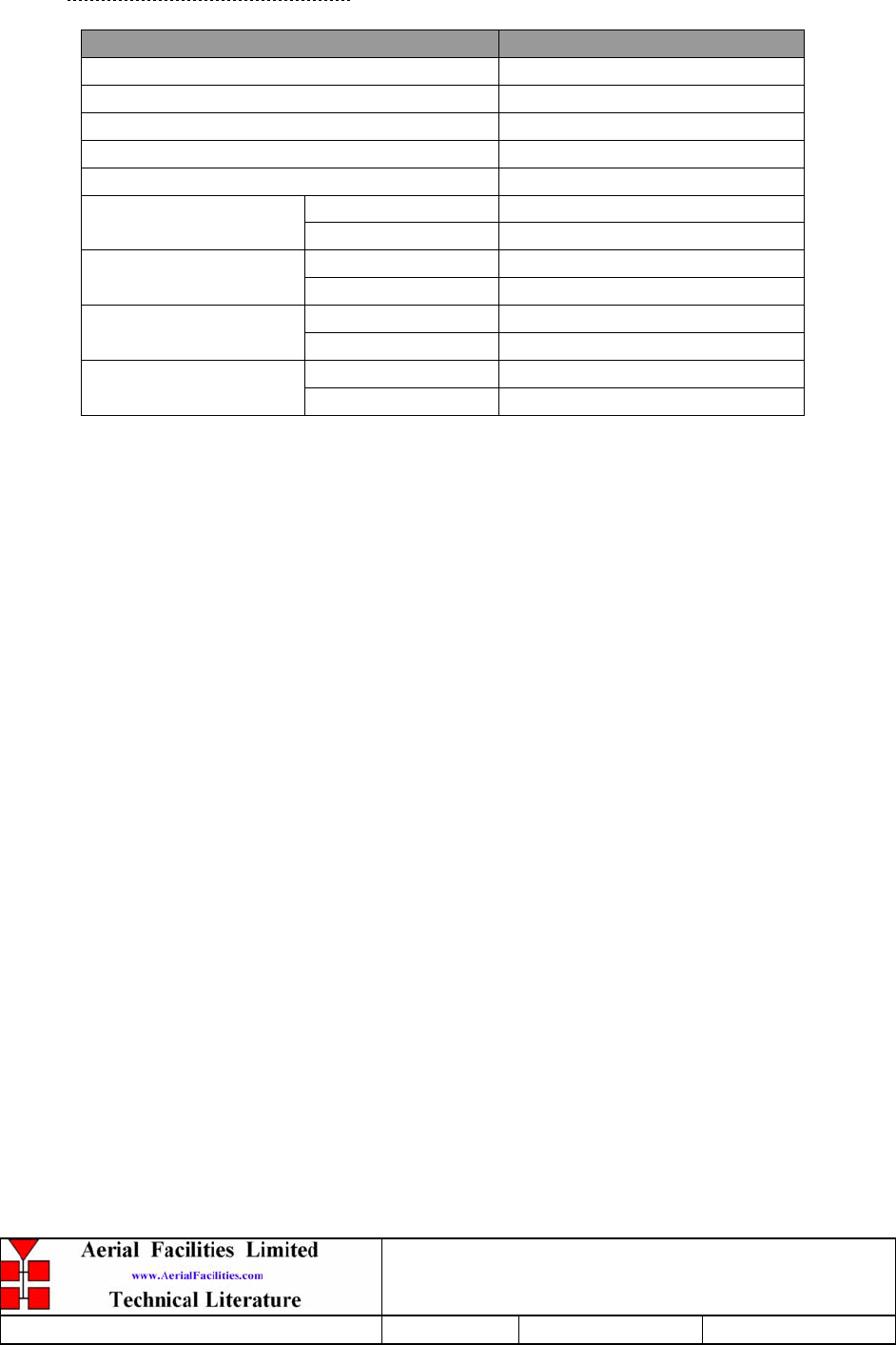
800MHz & VHF Cell Enhancers
Maintenance Handbook
H/book Number:-50-078001HBKM Issue No:-A Date:-02/09/2004 Page:-72 of 88
5.22.2 Technical Specification
PARAMETER SPECIFICATION
Frequency Range: up to 1000MHz
Attenuation Range: 3 to 30dB
Attenuation Steps: continuously variable
VSWR: better than 1.2:1
RF Connectors: SMA female
attenuator: 1W
Power Handling: detector/amp: >30W (or as required)
operation: -10°C to +60°C
Temperature Range: storage: -20°C to +70°C
attenuator pcb 50 x 42 x 21mm
Size: detector/amp pcb 54 x 42 x 21mm
attenuator: 90gm
Weight: detector/amp: 100gm
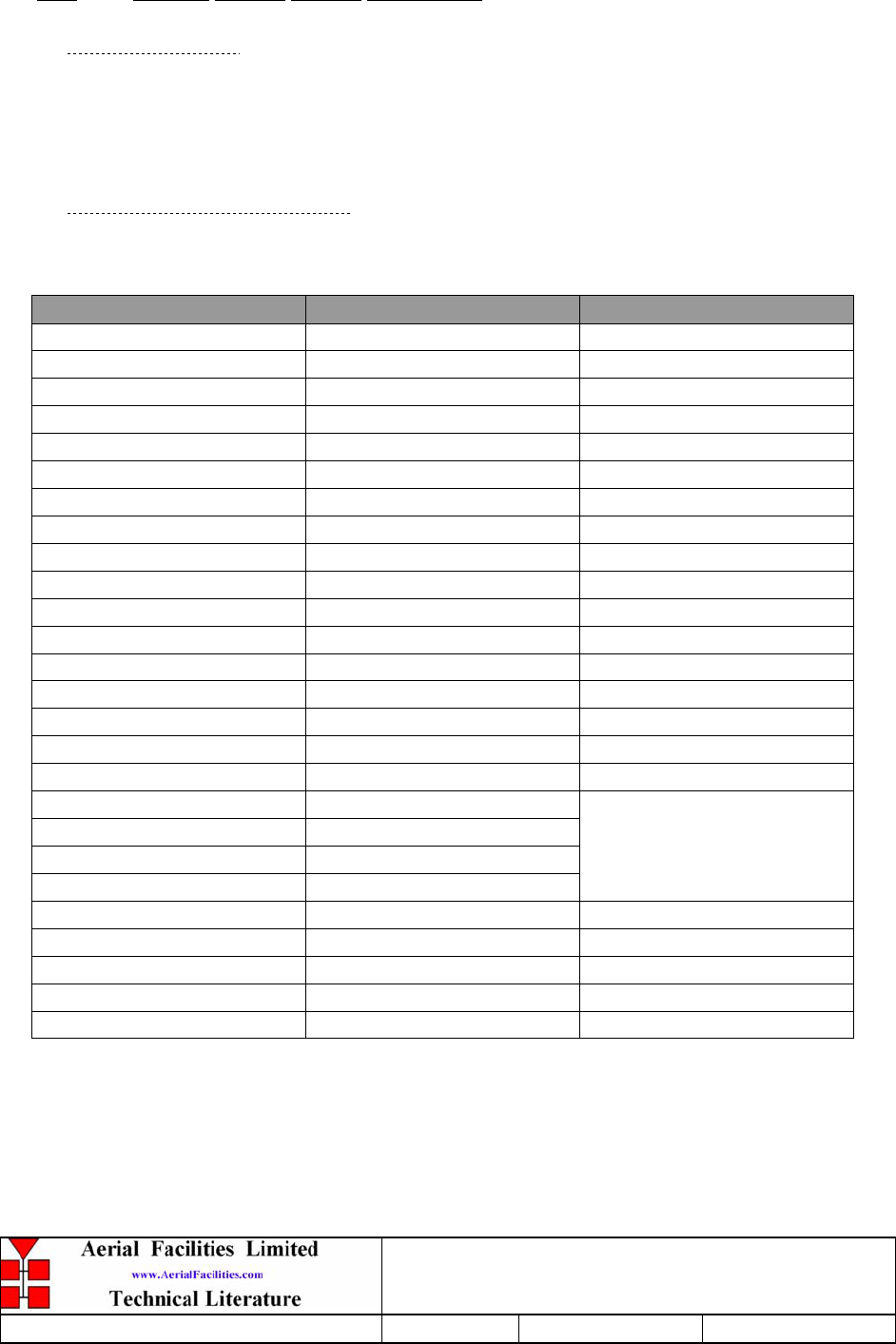
800MHz & VHF Cell Enhancers
Maintenance Handbook
H/book Number:-50-078001HBKM Issue No:-A Date:-02/09/2004 Page:-73 of 88
5.23 Channel Control Module (17-002101)
5.23.1 Description
The purpose of the channel control modules is to change the channel selective module
frequencies by means of a series of D.I.P switch banks, each switch corresponding to a different
‘frequency bit’.
5.23.2 Technical Specification
Below shows the pin assignments for each switch on a channel control module.
IDC PIN 25-way Connector Function
1 13 Freq. bit 1 (12.5kHz)
2 25 Freq. bit 2 (25kHz)
3 12 Freq. bit 3 (50kHz)
4 24 Freq. bit 4 (100kHz)
5 11 Freq. bit 5 (200kHz)
6 23 Freq. bit 6 (400kHz)
7 10 Freq. bit 7 (800kHz)
8 22 Freq. bit 8 (1.6MHz)
9 9 Freq. bit 9 (3.2MHz)
10 21 Freq. bit 10 (6.4MHz)
11 8 Freq. bit 11 (12.8MHz)
12 20 Freq. bit 12 (25.6MHz)
13 7 Freq. bit 13 (51.2MHz)
14 19 Freq. bit 14 (102.4MHz)
15 6 Freq. bit 15 (204.8MHz)
16 18 Freq. bit 16 (409.6MHz)
17 5 Module alarm
18 17
19 4
20 16
21 3
N/C
22 15 +5V
23 2 0V
24 14 Switched 12V
25 1 0V
26 --- ---
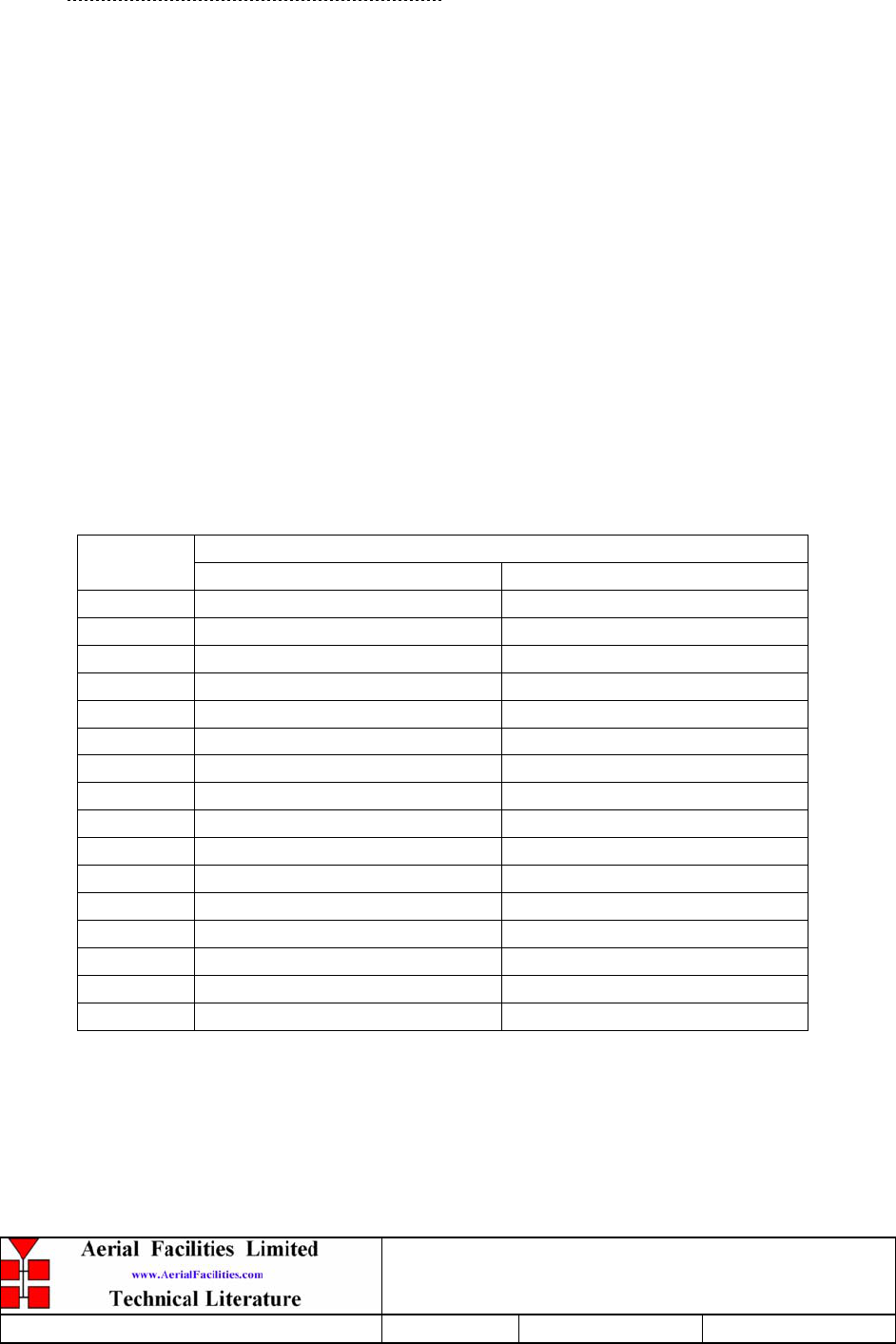
800MHz & VHF Cell Enhancers
Maintenance Handbook
H/book Number:-50-078001HBKM Issue No:-A Date:-02/09/2004 Page:-74 of 88
5.23.3 900MHz Programming Procedure
Check that the required downlink and uplink frequencies fall within the operational band limits
of the Cell Enhancer.
For each Downlink and Uplink channel frequency, subtract the appropriate synthesiser offset
frequency from the required operational frequency and record the resulting local oscillator
frequencies.
Divide each Downlink and Uplink local oscillator frequency by the synthesiser channel spacing
and check that the result is an integer (ie: no remainder).
If the synthesiser division ratio is not an integer value, check the required operational frequency
and repeat the calculation checking for mistakes.
Convert the required local oscillator frequency to synthesiser programming switch state patterns
according to the following table.
NOTE: Ensure that the correct column is used from the table below according to the synthesiser
channel spacing of the particular channel modules fitted to the Cell Enhancer.
Synthesiser offset added when switch in UP position Switch
Number 25kHz channel spacing 100kHz channel spacing
1 +25kHz +100kHz
2 +50kHz +200kHz
3 +100kHz +400kHz
4 +200kHz +800kHz
5 +400kHz +1.6MHz
6 +800kHz +3.2MHz
7 +1.6MHz +6.4MHz
8 +3.2MHz +12.8MHz
9 +6.4MHz +25.6MHz
10 +12.8MHz +51.2MHz
11 +25.6MHz +102.4MHz
12 +51.2MHz +204.8MHz
13 +102.4MHz +409.6MHz
14 +204.8MHz +819.2MHz
15 +409.6MHz -
16 +819.2MHz -
800MHz & VHF Cell Enhancers
Maintenance Handbook
H/book Number:-50-078001HBKM Issue No:-A Date:-02/09/2004 Page:-75 of 88
5.23.4 900MHz Programming Example
Frequency required: 958.0 MHz
Channel spacing: 25 kHz
Synthesiser offset: 70 MHz
The Local Oscillator frequency is therefore:
958.0 – 70 = 888 MHz
Dividing the LO frequency by the channel spacing of 0.025 MHz:
888.0 = 35520
0.025
This is an integer value, therefore it is OK to proceed.
Local Oscillator
Frequency
Switch settings
16 15 14 13 12 11 10 9 8 7 6 5 4 3 2 1
888.0 MHz 1 0 0 0 1 0 1 0 1 1 0 0 0 0 0 0
Switch setting: 0 = switch DOWN (on, frequency ignored)
1 = switch UP (off, frequency added)

800MHz & VHF Cell Enhancers
Maintenance Handbook
H/book Number:-50-078001HBKM Issue No:-A Date:-02/09/2004 Page:-76 of 88
5.24 Channel Selective Modules (17-009127 UHF, & 17-009135 VHF)
5.24.1 Description
The channel selectivity module is employed when the Cell Enhancer requirement dictates
that very narrow bandwidths (single operating channels), must be selected from within the
operating passband. One channel selectivity module is required for each channel.
The Channel Selectivity Module is an Up/Down frequency converter that mixes the incoming
channel frequency with a synthesised local oscillator, so that it is down-converted to an
Intermediate Frequency (IF) in the upper HF range. An eight pole crystal filter in the IF
amplifier provides the required selectivity to define the operating passband of the Cell
Enhancer to a single PMR channel. The same local oscillator then converts the selected IF
signal back to the channel frequency.
Selectivity is obtained from a fixed bandwidth block filter operating at an intermediate
frequency (IF) in the low VHF range. This filter may be internal to the channel selectivity
module (Crystal or SAW filter) or an externally mounted bandpass filter, (LC or Helical
Resonator). Various IF bandwidths can therefore be accommodated. A synthesized Local
Oscillator is employed in conjunction with high performance frequency mixers, to translate
between the signal frequency and IF.
The operating frequency of each channel selectivity module is set by the programming of
channel selectivity module frequencies and is achieved digitally, via hard wired links, banks
of DIP switches, or via an onboard RS232 control module, providing the ability to remotely
set channel frequencies.
Automatic Level Control (ALC) is provided within each channel selectivity module such that
the output level is held constant for high level input signals. This feature prevents saturation
of the output mixer and of the associated amplifiers.
Alarms within the module inhibit the channel if the synthesised frequency is not locked. The
synthesiser will not usually go out of lock unless a frequency far out of band is programmed.
The channel selectivity module is extremely complex and, with the exception of channel
frequency programming within the design bandwidth, it cannot be adjusted or repaired
without extensive laboratory facilities and the necessary specialised personnel. If a fault is
suspected with any channel selectivity module it should be tested by substitution and the
complete, suspect module should then be returned to AFL for investigation.
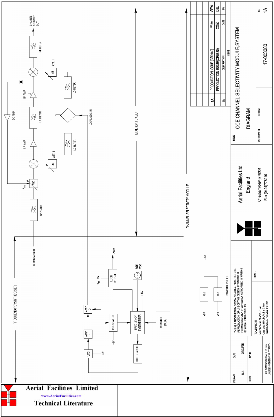
800MHz & VHF Cell Enhancers
Maintenance Handbook
H/book Number:-50-078001HBKM Issue No:-A Date:-02/09/2004 Page:-77 of 88
5.24.2 Drg. N. 17-003080, Generic Channel Module Block Diagram
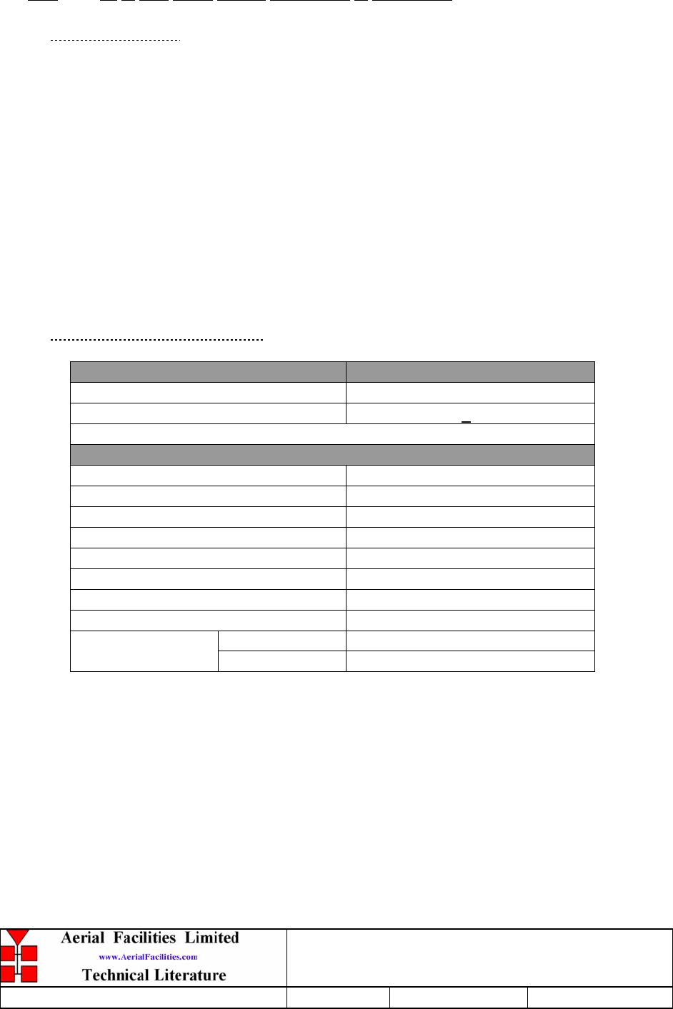
800MHz & VHF Cell Enhancers
Maintenance Handbook
H/book Number:-50-078001HBKM Issue No:-A Date:-02/09/2004 Page:-78 of 88
5.25 12 & 24V Relay Boards (20-001601 & 20-001602)
5.25.1 Description
The General Purpose Relay Board allows the inversion of signals and the isolation of
circuits. It is equipped with two dual pole change-over relays RL1 and RL2, with
completely isolated wiring, accessed via screw terminals.
Both relays are provided with polarity protection diodes and diodes for suppressing the
transients caused by "flywheel effect" which can destroy switching transistors or induce
spikes on neighbouring circuits. It’s common use is to amalgamate all the alarm signals into
one, volts-free relay contact pair for the main alarm system.
Note that the board is available for different voltages (12 or 24V) depending on the type of
relays fitted at RL1 and RL2.
5.25.2 Technical Specification
PARAMETER SPECIFICATION
Operating voltage: 8 to 30V (floating earth)
Alarm Threshold: Vcc - 1.20 volt +15%
Alarm output relay contacts:
Max. switch current: 1.0Amp
Max. switch volts: 120Vdc/60VA
Max. switch power: 24W/60VA
Min. switch load: 10.0µA/10.0mV
Relay isolation: 1.5kV
Mechanical life: >2x10⁷ operations
Relay approval: BT type 56
Connector details: Screw terminals
operational: -10°C to +55°C
Temperature range storage: -40°C to +70°C
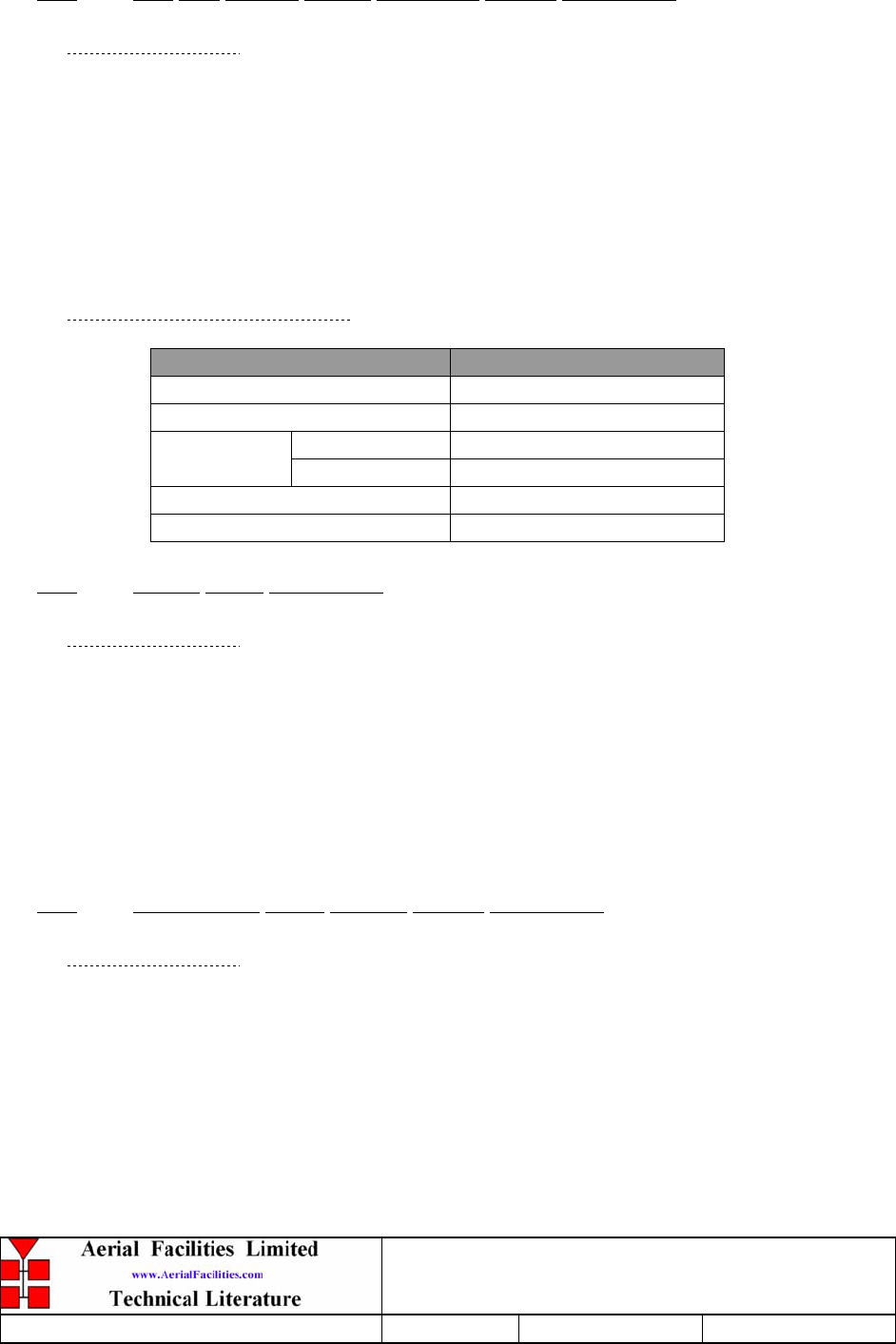
800MHz & VHF Cell Enhancers
Maintenance Handbook
H/book Number:-50-078001HBKM Issue No:-A Date:-02/09/2004 Page:-79 of 88
5.26 12V Low Voltage Battery Disconnect Module (80-061003)
5.26.1 Description
The low voltage disconnect module’s main function is to monitor the battery voltage as
the batteries discharge. When a pre-set value has been reached (usually 21.5V DC) the
unit will disconnect the batteries to prevent a ‘deep discharge’ state which, if allowed to
continue, could irreparably damage the batteries, necessitating replacement. The unit’s
other function is to regulate the battery voltage to the cell enhancer equipment to 23.5V
when in back-up mode (the terminal voltage of fully charged batteries is likely to be
higher than 27V, and therefore potentially damaging to electronics in the system).
5.26.2 Technical Specification
PARAMETER SPECIFICATION
Operating voltage: 9-16V
Low voltage cut-off point: 10.5V (factory set)
operation: -10°C to +55°C Temperature
range storage: -20°C to +70°C
Weight: <1kg
Size: 109.98 x 55.88mm
5.27 Crystal Filters (93-980109)
5.27.1 Description
Crystal filters are fitted at the inputs and outputs of the simplex/duplex shelves (instead of
bandpass filters) in order to maximise the excellent isolation and rejection characteristics of
these narrow-band devices. It is easier to achieve close channel spacing using crystal filters,
however, due to the increased insertion losses, higher gain amplification is needed when
they are utilised.
5.28 IXFN170N10 Power Mos-Fet Module (94-030015)
5.28.1 Description
This power module is simply a power MOS-FET transistor which is the series regulator for
the main 24V DC battery output voltage rail. It is enabled/disabled from the discriminator
module, (see section 5.2) has fast switch-off characteristics and a low forward volt drop. It is
attached to a heatsink assembly mounted on the side of the case.
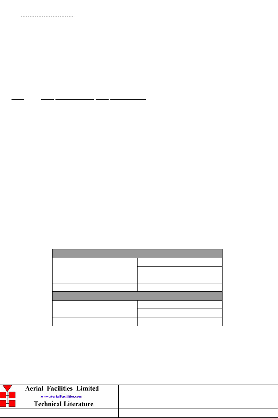
800MHz & VHF Cell Enhancers
Maintenance Handbook
H/book Number:-50-078001HBKM Issue No:-A Date:-02/09/2004 Page:-80 of 88
5.29 STPS12045TV 60A Dual Diode Assembly (94-100004)
5.29.1 Description
The purpose of these dual diode assemblies is to allow two (or more) DC voltage sources to
be combined, so that the main 12 or 24 volt DC rail within the equipment is sourced from
either the mains driven flat-pack, or externally through an XLR connector on the rear panel.
The heavy-duty diodes prevent any reverse current from flowing back to their source or the
alternative supply rail. Combining diodes such as these will also be used if the equipment is
to be powered from external back-up batteries.
5.30 15V Switch-Mode PSU (96-300054)
5.30.1 Description
The power supply unit is a switched-mode type capable of supplying 15V DC at 27Amps
continuously. The amplifiers in this unit will draw approximately 20-22Amps at 24V DC,
so the PSU will be used conservatively ensuring a long operational lifetime.
No routine maintenance of the PSU is required. If a fault is suspected, then the output
voltage from the power supply may be measured on its output terminals. This is typically
set to 15.2V. The adjustment potentiometer will be found close to the DC output
terminals.
All the PSU’s used in AFL Cell Enhancers are capable of operation from either 110 or
220V nominal AC supplies. The line voltage is sensed automatically, so no adjustment or
link setting is needed by the operator.
5.30.2 Technical Specification
AC Input Supply:
110 or 220V nominal
Voltage: 90 to 132 or 180 to 264V
(absolute limits)
Frequency: 47 to 63Hz
DC Output Supply:
15V DC (nominal)
Voltage: 12.5-17V (absolute limits)
Current: 27.0A

800MHz & VHF Cell Enhancers
Maintenance Handbook
H/book Number:-50-078001HBKM Issue No:-A Date:-02/09/2004 Page:-81 of 88
6. INSTALLATION
6.1 Initial Installation Record
When this equipment is initially commissioned, please use the equipment set-up record sheet
in Appendix A. This will help both the installation personnel and AFL should these figures
be needed for future reference or diagnosis.
6.1.1 Rack Mounted Equipment
Installation will be a matter of securing each shelf into its appropriate place in the rack
cabinet, connecting all the cables (RF, DC and alarm) to their correct ports/connectors and
system testing (at the customer’s discretion) to prove the original specification. Care should
be exercised when moving the 8U chassis as the weight may surprise an operator. Power
should not be applied until all connections have been double-checked and verified.
6.1.2 Wall Mounted Equipment
The size and weight of the wall mounting enclosure(s) mean that they represent a significant
weight hazard when fitting. In the interests of safety this should be done before any
electrical, RF, or alarm connections are made.
The equipment must be located on a perpendicular, flat surface that is made from a material
suitable for bearing the weight of the whole assembly with attached cables. If the installer is
in any doubt about the suitability of a site it is recommended that he consult with an
appropriately qualified Structural Engineer.
It is important in determining the location of the units that space is allowed for access to the
front and underneath of the equipment. To enable maintenance to be carried out, the door
must be able to open fully.
The location should be served with a duct to allow the entry of cables into the equipment.
6.1.3 Electrical Connections
The power supply is connected to the equipment via an IP65 connector located on the
bottom or side surface. It is recommended that the connection is made by a qualified
electrician, who must satisfy himself that the supply will be the correct voltage and of
sufficient capacity.
All electrical and RF connection should be completed and checked prior to power being
applied for the first time.
Ensure that connections are kept clean and are fully tightened.

800MHz & VHF Cell Enhancers
Maintenance Handbook
H/book Number:-50-078001HBKM Issue No:-A Date:-02/09/2004 Page:-82 of 88
6.1.4 RF Connections
All RF connections are made to the cable termination, located on the bulkhead at the rear of
the equipment at floor level (rack equipment). Care must be taken to ensure that the correct
connections are made with particular attention made to the base station Tx/Rx ports. In the
event that the base transmitter is connected to the Rx output of the rack, damage to the
equipment will be done if the base station transmitter is then keyed.
Again, ensure that connections are kept clean and are fully tightened.
6.2 Commissioning
Once all connections are made the equipment is ready for commissioning.
To commission the system the test equipment detailed in Section 7.2 will be required.
Using the system diagrams and the end-to-end test specification, the equipment should be
tested to ensure correct operation.
On initial power up the system alarm indicators on the front panels of the equipment should
be checked. A red LED illuminated indicates a fault in an amplifier module that must be
investigated before proceeding with the commissioning. A green LED on the door
illuminates, to indicate that the power supply is connected and active.
In the event that any part of the system does not function correctly as expected, check all
connections to ensure that they are to the correct port, that the interconnecting cables are not
faulty and that they are tightened. The majority of commissioning difficulties arise from
problems with the interconnecting cables and connectors.
6.3 Quick Fault Checklist
All AFL equipment is individually tested to specification prior to despatch. Failure of this
type of equipment is not common. Experience has shown that a large number of fault
conditions relating to installations result from simple causes often occurring as result of
transportation, unpacking and installation. Below are listed some common problems which
have resulted in poor performance or an indicated non-functioning of the equipment.
• Mains power not connected or not switched on.
• External connectors not fitted or incorrectly fitted.
• Internal connectors/ports becoming loose due to transport vibration.
• Wiring becoming detached as a result of heavy handling.
• Input signals not present due to faults in the aerial and feeder system.
• Base transmissions not present due to faults at the base station.
• Modems fitted with incorrect software configuration/and or PIN N’s.
• Changes to channel frequencies and inhibiting channels.
• Hand held radio equipment not correctly set to repeater channels.
• Hand held radio equipment not correctly set to base station.

800MHz & VHF Cell Enhancers
Maintenance Handbook
H/book Number:-50-078001HBKM Issue No:-A Date:-02/09/2004 Page:-83 of 88
7. MAINTENANCE
7.1 General Procedures
7.1.1 Basic Fault Finding
In the event that the performance of the system is suspect, a methodical and logical approach
to the problem will reveal the cause of the difficulty. The System consists of modules fitted
within an 8U shelf and housed within a standard 19” rack type cabinet.
Transmissions from the main base stations are passed though the system to the mobile radio
equipment; this could be a handheld radio or a transceiver in a vehicle. This path is referred
to as the downlink. The return signal path from the mobile radio equipment to the base
station is referred to as the uplink.
The first operation is to check the alarms of each of the active units and determine that the
power supplies to the equipment are connected and active.
This can be achieved remotely (via CEMS, the RS232 Coverage Enhancement Management
System, if fitted), or locally with the front panel LED’s. The green LED on the front panel
should be illuminated, while the red alarm indicator should be off.
If an Alarm is on, then that individual module must be isolated and individually tested
against the original test specification.
The amplifier units within the shelf have a green LED showing through a hole in their cover,
which is illuminated if the unit is working correctly.
If an amplifier is suspect, check the DC power supply to the unit. If no other fault is
apparent use a spectrum analyser to measure the incoming signal level at the input and then
after reconnecting the amplifier input, measure the output level. Consult with the system
diagram to determine the expected gain and compare result.
In the event that there are no alarms on and all units appear to be functioning it will be
necessary to test the system in a systematic manner to confirm correct operation.

800MHz & VHF Cell Enhancers
Maintenance Handbook
H/book Number:-50-078001HBKM Issue No:-A Date:-02/09/2004 Page:-84 of 88
7.1.2 Downlink
Confirm that there is a signal at the expected frequency and strength from the base station. If
this is not present then the fault may lay outside the system. To confirm this, inject a
downlink frequency signal from a known source at the master site BTS input and check for
output at the remote site feeder output.
If a signal is not received at the output it will be necessary to follow the downlink path
through the system to find a point at which the signal is lost. The expected downlink output
for the given input can be found in the end-to-end test specification.
7.1.3 Uplink
Testing the uplink involves a similar procedure to the downlink except that the frequencies
used are those transmitted by the mobile equipment.
7.1.4 Fault repair
Once a faulty component has been identified, a decision must be made on the appropriate
course to carry out a repair. A competent engineer can quickly remedy typical faults such as
faulty connections or cables. The exceptions to this are cable assemblies connecting
bandpass filter assemblies that are manufactured to critical lengths to maintain a 50-ohm
system. Care should be taken when replacing cables or connectors to ensure that items are of
the correct specification. The repair of component modules such as amplifiers and bandpass
filters will not usually be possible in the field, as they frequently require specialist
knowledge and test equipment to ensure correct operation. It is recommended that items of
this type are replaced with a spare unit and the faulty unit returned to AFL for repair.

800MHz & VHF Cell Enhancers
Maintenance Handbook
H/book Number:-50-078001HBKM Issue No:-A Date:-02/09/2004 Page:-85 of 88
7.1.5 Checking service
Following the repair of any part of the system it is recommended that a full end-to-end test is
carried out in accordance with the test specification and that the coverage is checked by
survey.
It is important to bear in mind that the system includes a radiating cable network and base
stations that may be faulty or may have been damaged.
7.1.6 Service Support
Advice and assistance with maintaining and servicing this system are available by contacting
Aerial Facilities Ltd.
7.2 Tools & Test Equipment
The minimum tools and test equipment needed to successfully service this AFL product are
as follows:-
Spectrum analyser: 100kHz to 2GHz (Dynamic range = 90dB).
Signal Generator: 30MHz to 2GHz (-120dBm to 0dBm o/p level).
Attenuator: 20dB, 10W, DC-2GHz, (N male – N female).
Test Antenna: Yagi or dipole for operating frequency.
Digital multi-meter: Universal Volt-Ohm-Amp meter.
Test cable x 2: N male – N male, 2M long RG214.
Test cable x 2: SMA male – N male, 1m long RG223.
Hand tools: Philips #1&2 tip screwdriver.
3mm flat bladed screwdriver.
SMA spanner and torque setter.

800MHz & VHF Cell Enhancers
Maintenance Handbook
H/book Number:-50-078001HBKM Issue No:-A Date:-02/09/2004 Page:-86 of 88
7.3 Care of Modules
7.3.1 General Comments
Many of the active modules contain semiconductor devices utilising MOS technology, which
can be damaged by electrostatic discharge. Correct handling of such modules is mandatory to
ensure their long-term reliability.
To prevent damage to a module, it must be withdrawn/inserted with care. The module may
have connectors on its underside, which might not be visible to the service operative.
7.3.2 Module Removal (LNA’s, general procedure):
The following general rules should be followed to remove a module:
1 Remove power to the unit
2 Remove all visible connectors (RF, DC & alarm)
3 Release module retaining screws.
4 Slowly but firmly, pull the module straight out of its position. Take care not to twist/turn
the module during withdrawal. (When the module is loose, care may be needed, as there
may be concealed connections underneath).
7.3.3 Module Replacement (general):
1 Carefully align the module into its location then slowly push the module directly straight
into its position, taking care not to twist/turn it during insertion.
2 Reconnect all connectors, RF, alarm, power etc.,(concealed connectors may have to be
connected first).
3 Replace retaining screws (if any).
4 Double-check all connections before applying power.
7.3.4 Power Amplifiers
1) Remove power to the unit. (Switch off @ mains/battery, or remove DC in connector)
2) Remove alarm wires from alarm screw terminal block or disconnect multi-way alarm
connector.
3) Carefully disconnect the RF input and output coaxial connectors (usually SMA)
If alarm board removal is not required, go to step 5.
4) There is (usually) a plate attached to the alarm board which fixes it to the amplifier,
remove its retaining screws and the alarm board can be withdrawn from the amplifier in
its entirety. On certain types of amplifier the alarm board is not mounted on a dedicated
mounting plate; in this case it will have to firstly be removed by unscrewing it from the
mounting pillars, in most cases, the pillars will not have not have to be removed before
lifting the amplifier.
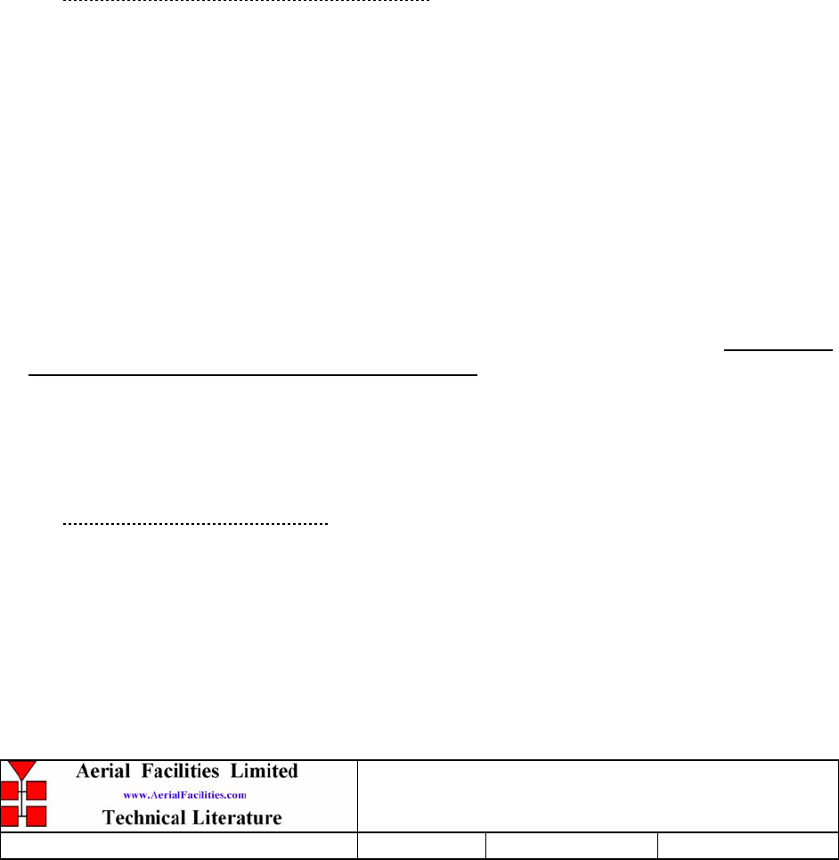
800MHz & VHF Cell Enhancers
Maintenance Handbook
H/book Number:-50-078001HBKM Issue No:-A Date:-02/09/2004 Page:-87 of 88
5) If the amplifier to be removed has a heatsink attached, there may be several different
ways it can have been assembled. The most commonly used method, is screws through
the front of the heatsink to threaded screw holes (or nuts and bolts), into the amplifier
within the main case. If the heatsink is mounted on the rear of the main case (e.g., against
a wall in the case of wall mounted enclosures), then the fixing method for the heatsink
will be from within the case, (otherwise the enclosure would have to be removed from the
wall in order to remove the heatsink).
When the heatsink has been removed, the amplifier may be unscrewed from the main
casing by its four corner fixings and gently withdrawn.
Fitting a new power amplifier module will be the exact reverse of the above.
Note: Do not forget to apply fresh heatsink compound to the heatsink/main case
joint and also between the amplifier and the main case.
7.3.5 Low Power Amplifier Replacement
1 Disconnect the mains power supply and disconnect the 24V dc supply connector for the
LPA.
2 Disconnect the RF input and output cables from the LPA.
3 Disconnect the alarm connector.
4 Remove the alarm monitoring wires from (D type connector) pins 9 and 10.
5 Remove the LPA module by removing the four retaining screws, replace with a new
LPA module and secure it with the screws.
6 Connect the RF cables to the LPA input and output connectors. Reconnect the wires to
the alarm board connector pins 9 and 10.
7 Reconnect the DC supply connector and turn the mains switch on.
Note: Tighten SMA connectors using only a dedicated SMA torque spanner. If
SMA connectors are over-tightened, irreparable damage will occur. . Do not use
adjustable pliers to loosen/tighten SMA connectors.
Also take care not to drop or knock the module as this can damage (or misalign in the
case of tuned passive modules) sensitive internal components. Always store the modules
in an environmentally friendly location
7.3.6 Module Transportation:
To maintain the operation, performance and reliability of any module it must be stored and
transported correctly. Any module not installed in a whole system must be kept in an anti-
static bag or container. These bags or containers are normally identified by being pink or
black, and are often marked with an ESD label. Any module sent back to AFL for
investigation/repair must be so protected. Please contact AFL’s quality department before
returning a module.
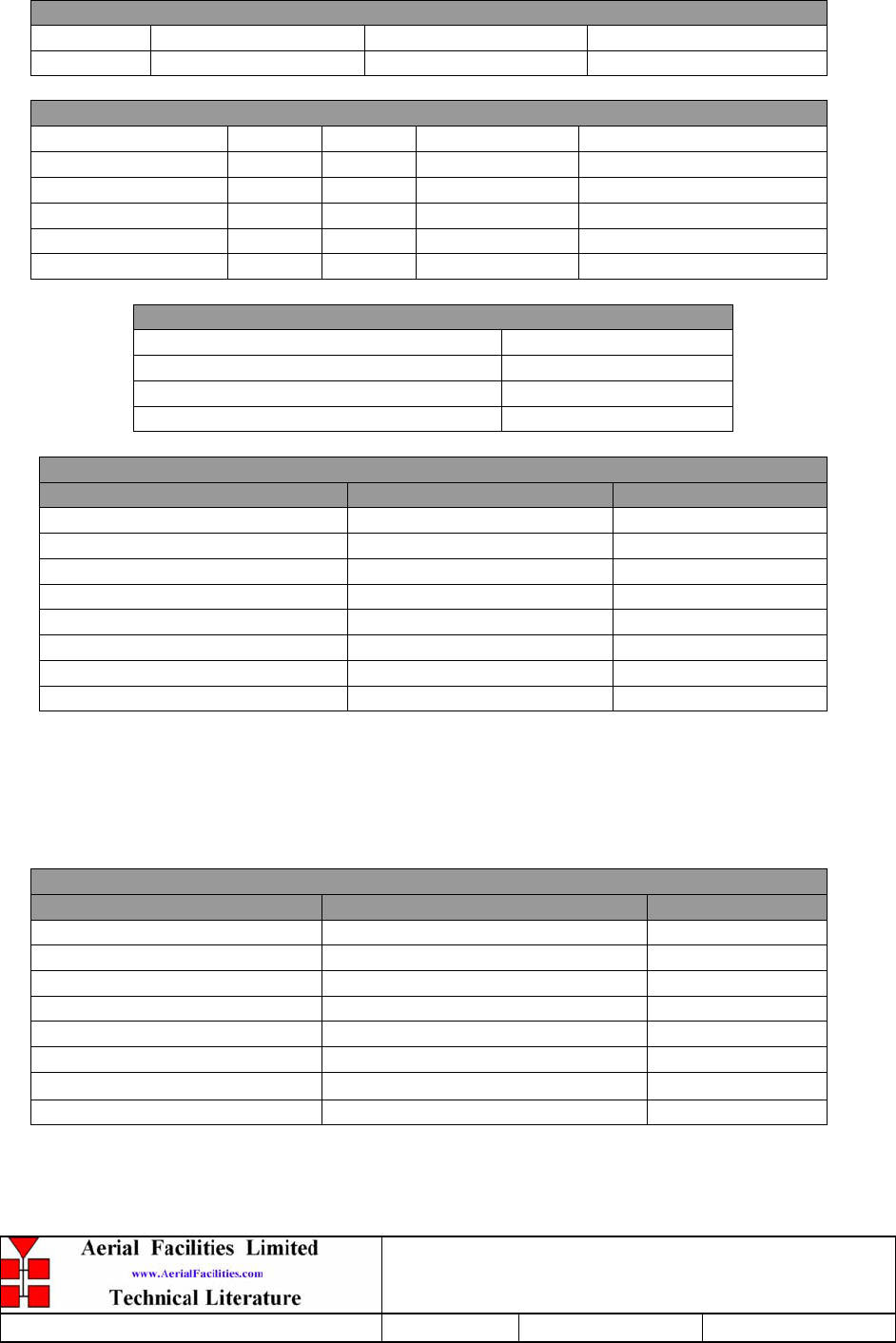
800MHz & VHF Cell Enhancers
Maintenance Handbook
H/book Number:-50-078001HBKM Issue No:-A Date:-02/09/2004 Page:-88 of 88
APPENDIX A INITIAL EQUIPMENT SET-UP CALCULATIONS
GENERAL INFORMATION
Site Name: Client Name:
Date: AFL Equip. Model N.
ANTENNA SYSTEMS
Model Gain Azimuth Comments
A - Service Antenna
B – Donor Antenna
Type Loss Length Comments
C – Service Feeder
D – Donor Feeder
INITIAL PARAMETERS
E – CE Output Power dBm
F – Antenna Isolation dB
G – Input signal level from donor BTS dBm
Operating Voltage V
DOWNLINK CALCULATIONS
Parameter Comments Value
Input signal level (G) dBm
CE max. o/p power (E) dBm
Gain setting E - G dB
Isolation required (Gain + 10dB) dB
Service antenna gain (A) dB
Service antenna feeder loss (C) dB
Effective radiated power (ERP) E+A-C dBm
Attenuator setting CE gain-gain setting dB
If the input signal level in the uplink path is known and steady, use the following calculation
table to determine the gain setting. If the CE features Automatic Gain Control the attenuator
should be set to zero and if not, then the attenuation setting for both uplink and downlink
should be similar.
UPLINK CALCULATIONS
Parameter Comments Value
Input signal level dBm
CE max. o/p power (E) dBm
Gain setting dB
Required isolation dB
Donor antenna gain (B) dB
Donor antenna feeder loss (D) dB
Effective radiated power (ERP) E+B-D dBm
Attenuator setting (CE gain-gain setting) dB