PBE Europe as Axell Wireless 55-1549BDA UHF Remote Repeater System 55-154901 User Manual Weehawken River Portal
Axell Wireless UHF Remote Repeater System 55-154901 Weehawken River Portal
UserManual.wiki
>
PBE Europe as Axell Wireless
>
55 1549BDA User Manual
User manual
Navigation menu
Upload a User Manual
Namespaces
Wiki Guide
HTML
PDF
Info
Views
User Manual
Discussion / Help
Navigation

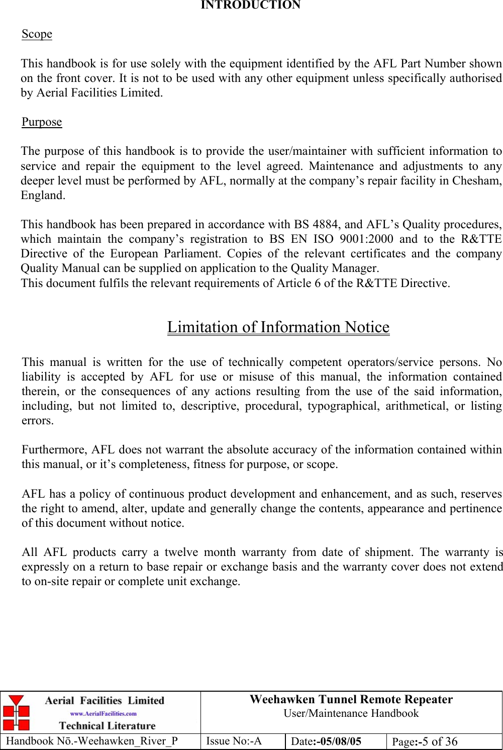
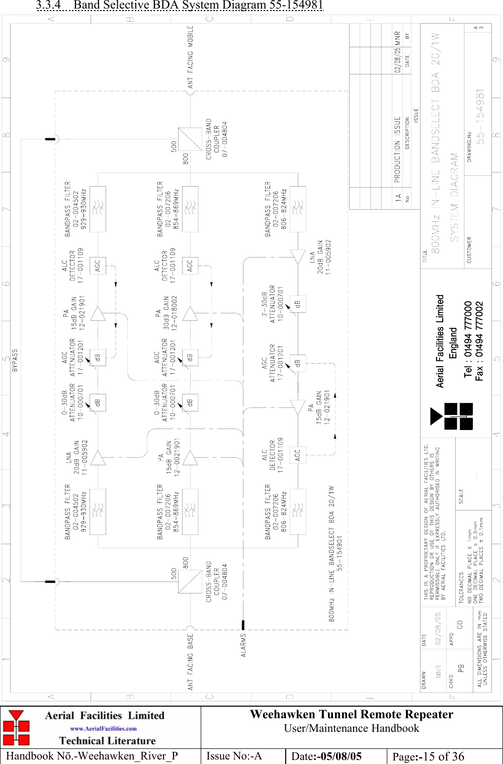
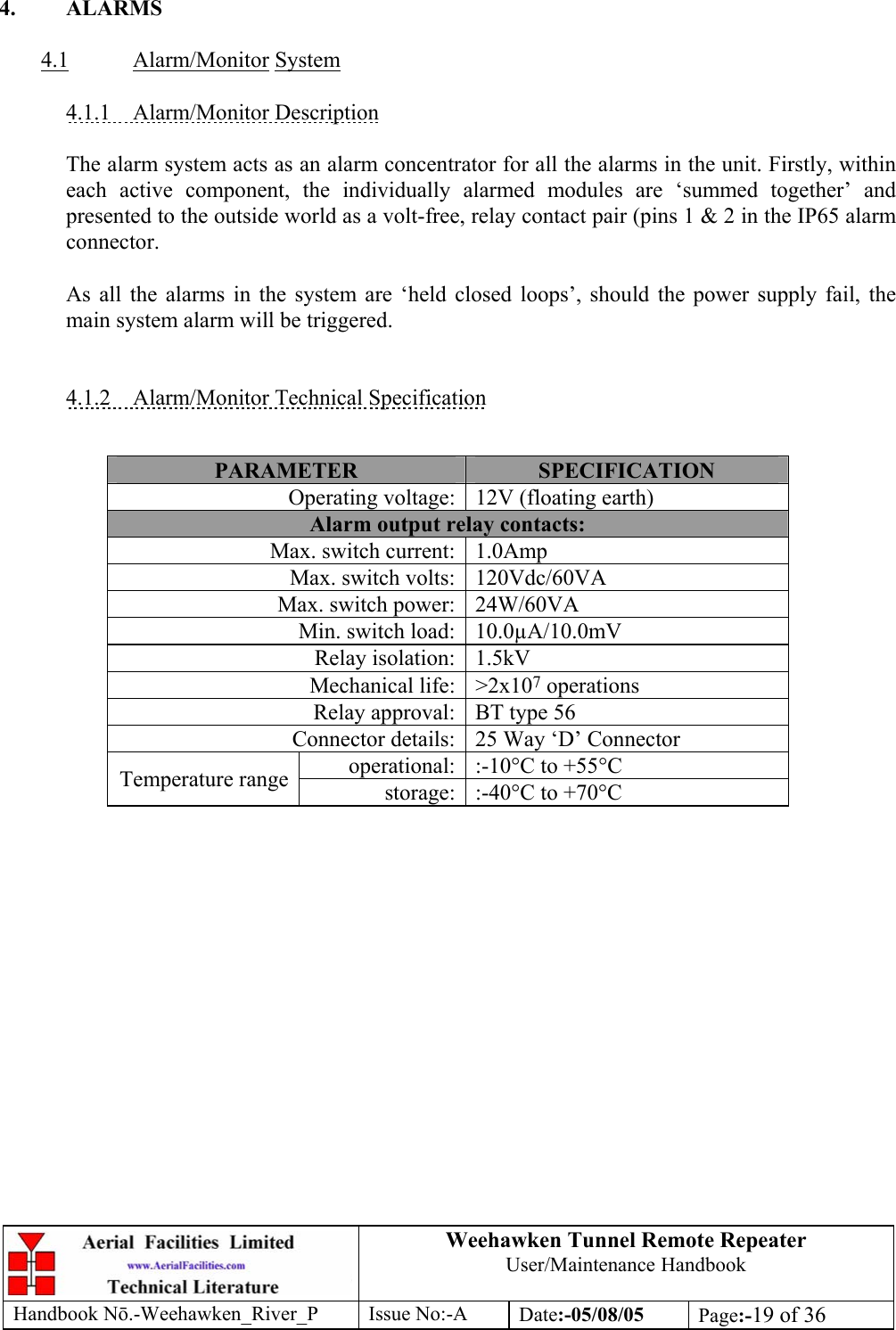
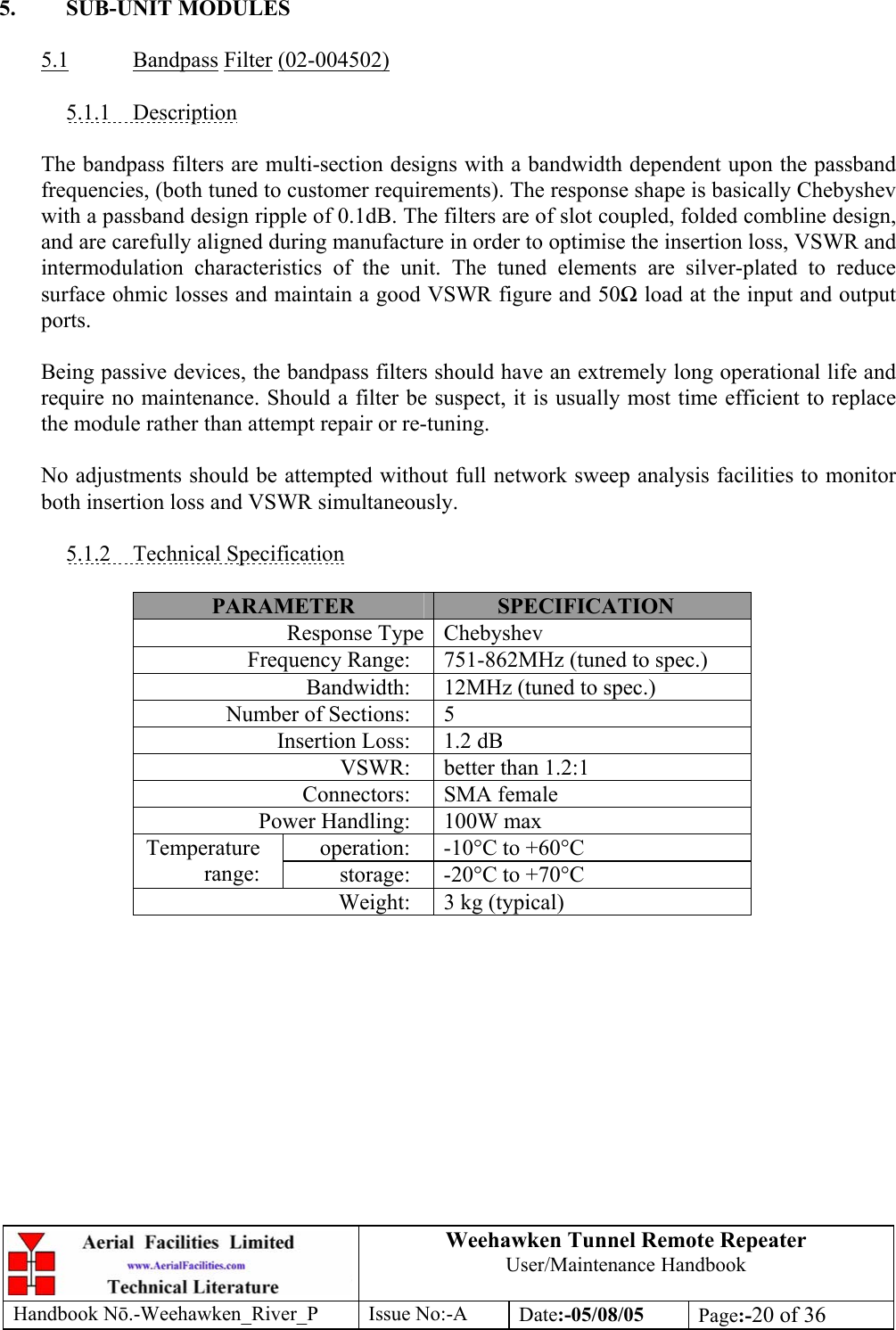
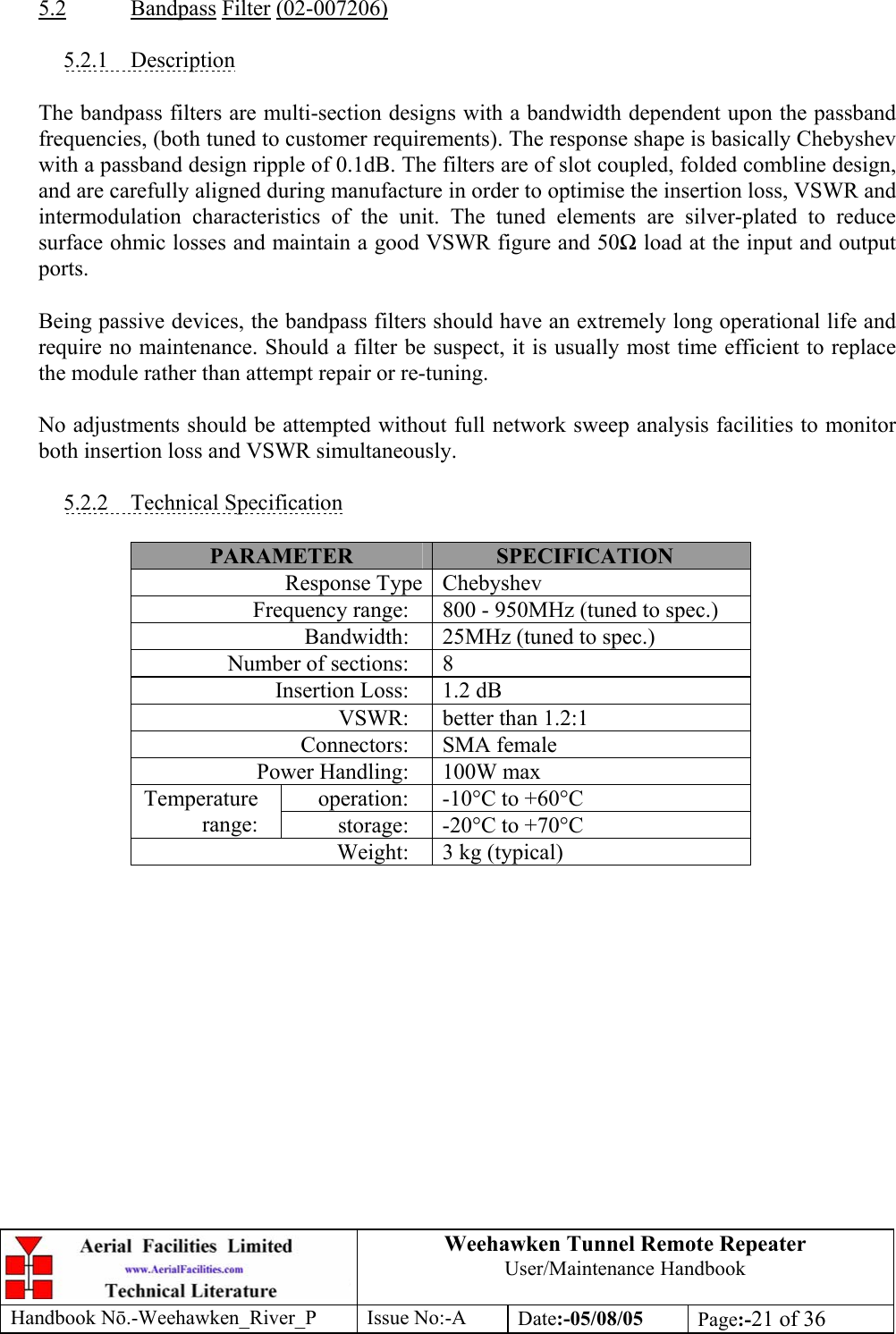
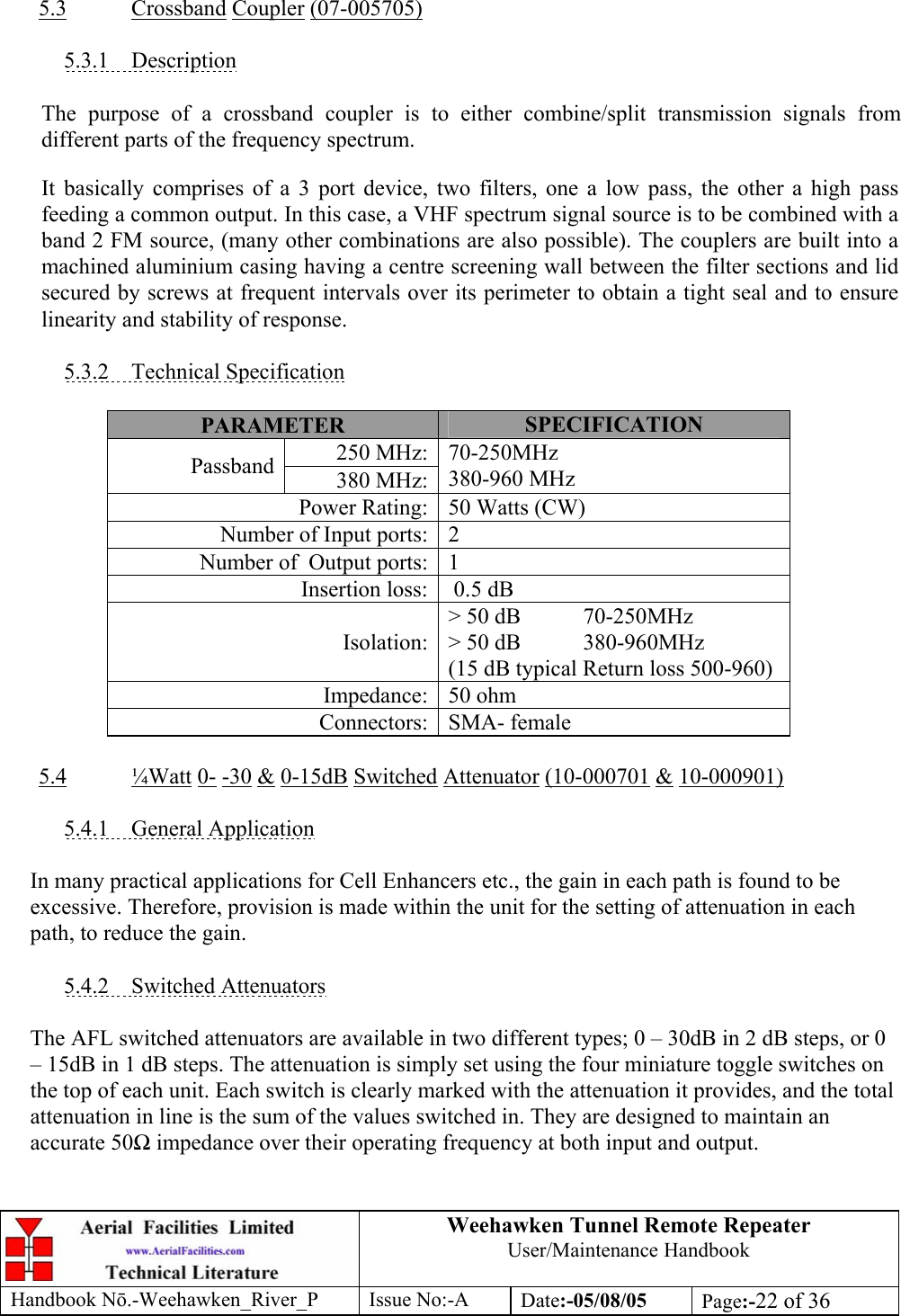
![Weehawken Tunnel Remote Repeater User/Maintenance Handbook Handbook Nō.-Weehawken_River_P Issue No:-A Date:-05/08/05 Page:-6 of 36 EC DECLARATION OF CONFORMITY In accordance with BS EN ISO/IEC 17050-1&-2:2004 AERIAL FACILITIES LTD Aerial House Asheridge Road Chesham Bucks HP5 2QD United Kingdom DECLARES, UNDER OUR SOLE RESPONSIBILITY THAT THE FOLLOWING PRODUCT PRODUCT PART NO[S] 55-154901 PRODUCT DESCRIPTION Weehawken tunnel remote amplifier IN ACCORDANCE WITH THE FOLLOWING DIRECTIVES: 1999/5/EC The Radio & Telecommunications Terminal Equipment Directive Annex V and its amending directives HAS BEEN DESIGNED AND MANUFACTURED TO THE FOLLOWING STANDARD[S] OR OTHER NORMATIVE DOCUMENT[S]: BS EN 60950 Information technology equipment. Safety. General requirements ETS EN 301 489-1 EMC standard for radio equipment and services. Part 1. Common technical requirements I hereby declare that the equipment named above has been designed to comply with the relevant sections of the above referenced specifications. The unit complies with all essential requirements of the Directives. SIGNED B S BARTON TECHNICAL DIRECTOR DATE: 08/11/2005 0086](https://usermanual.wiki/PBE-Europe-as-Axell-Wireless/55-1549BDA/User-Guide-617739-Page-6.png)