PBE Europe as Axell Wireless 55-1549BDA UHF Remote Repeater System 55-154901 User Manual Weehawken River Portal
Axell Wireless UHF Remote Repeater System 55-154901 Weehawken River Portal
User manual

Weehawken Tunnel Remote Repeater
User/Maintenance Handbook
Handbook Nō.-Weehawken_River_P Issue No:-A Date:-05/08/05 Page:-1 of 36
Weehawken Tunnel Radio
Remote Repeater System
User/Maintenance Handbook
For
G.E Transport Systems
AFL Works Order Nō.: Q112727
AFL product part Nō.’s:
55-154901 (800MHz BS BDA)
80-231302 (800MHz Power Supply)
80-231303 (Alarm System)

Weehawken Tunnel Remote Repeater
User/Maintenance Handbook
Handbook Nō.-Weehawken_River_P Issue No:-A Date:-05/08/05 Page:-2 of 36
Table of Contents
INTRODUCTION ............................................................................................................................................5
Scope................................................................................................................................................................................ 5
Purpose............................................................................................................................................................................ 5
EC DECLARATION OF CONFORMITY.................................................................................................................. 6
Glossary of Terms .......................................................................................................................................................... 7
Key to AFL RF Module Drawing Symbols.................................................................................................................. 8
1. SAFETY CONSIDERATIONS ............................................................................................................9
1.1 Earthing of Equipment ..................................................................................................................................... 9
1.2 Electric Shock Hazard ......................................................................................................................................9
1.3 RF Radiation Hazard...................................................................................................................................... 10
1.4 Chemical Hazard............................................................................................................................................. 11
1.5 Emergency Contact Numbers ........................................................................................................................ 11
2. OVERVIEW/ SYSTEM DESCRIPTION..........................................................................................12
2.1 General System Description ........................................................................................................................... 12
3. MULTI-BAND SELECTIVE CELL ENHANCER (RIVER PORTAL).........................................13
3.3 Band Selective BDA (55-154901) ................................................................................................................... 13
3.3.1 Band Selective BDA Description...................................................................................................................13
3.3.2 Band Selective BDA Electrical Specification ................................................................................................13
3.3.3 Band Selective BDA Mechanical Specification............................................................................................. 14
3.3.4 Band Selective BDA System Diagram 55-154981......................................................................................... 15
3.3.5 Band Selective BDA Outline Drawing, Drg. Nō. 50-118181........................................................................16
3.3.6 Weehawken System Frequencies Look-up Table........................................................................................... 17
3.3.7 Band Selective BDA (55-154901) Parts List................................................................................................. 18
4. ALARMS.............................................................................................................................................. 19
4.1 Alarm/Monitor System ................................................................................................................................... 19
4.1.1 Alarm/Monitor Description........................................................................................................................... 19
4.1.2 Alarm/Monitor Technical Specification ........................................................................................................ 19
5. SUB-UNIT MODULES .......................................................................................................................20
5.1 Bandpass Filter (02-004502)........................................................................................................................... 20
5.1.1 Description....................................................................................................................................................20
5.1.2 Technical Specification ................................................................................................................................. 20
5.2 Bandpass Filter (02-007206)........................................................................................................................... 21
5.2.1 Description....................................................................................................................................................21
5.2.2 Technical Specification ................................................................................................................................. 21
5.3 Crossband Coupler (07-005705) .................................................................................................................... 22
5.3.1 Description....................................................................................................................................................22
5.3.2 Technical Specification ................................................................................................................................. 22
5.4 ¼Watt 0- -30 & 0-15dB Switched Attenuator (10-000701 & 10-000901)...................................................22
5.4.1 General Application ......................................................................................................................................22
5.4.2 Switched Attenuators..................................................................................................................................... 22
5.5 Low Noise Amplifier (11-005902) .................................................................................................................. 23
5.5.1 Description....................................................................................................................................................23
5.5.2 Technical Specification ................................................................................................................................. 23
5.6 Low Noise Amplifier (11-006702) .................................................................................................................. 24
5.6.1 Description....................................................................................................................................................24
5.6.2 Technical Specification ................................................................................................................................. 24
5.6.3 LNA ‘D’ Connector Pin-out details ..............................................................................................................24
5.7 20W Power Amplifier (12-018002) ................................................................................................................ 25
5.7.1 Description....................................................................................................................................................25
5.7.2 Technical Specification ................................................................................................................................. 25
5.7.3 PA 7-Way Connector Pin-outs ...................................................................................................................... 25

Weehawken Tunnel Remote Repeater
User/Maintenance Handbook
Handbook Nō.-Weehawken_River_P Issue No:-A Date:-05/08/05 Page:-3 of 36
5.8 800MHz 1Watt Low Power Amplifier (12-021901)...................................................................................... 26
5.8.1 Description....................................................................................................................................................26
5.8.2 Technical Specification ................................................................................................................................. 26
5.8.3 LPA 7-Way Connector Pin-outs....................................................................................................................26
5.9 Wide Dynamic Range AGC (17-001109, det. & 17-001201, atten.) ............................................................ 27
5.9.1 Description....................................................................................................................................................27
5.9.2 Technical Specification ................................................................................................................................. 28
5.10 12V Single Relay Board (80-008901) ............................................................................................................. 29
5.10.1 Description................................................................................................................................................29
5.10.2 Technical Specification ............................................................................................................................. 29
6. INSTALLATION.................................................................................................................................30
6.1 Wall Mounted Equipment.............................................................................................................................. 30
7. MAINTENANCE.................................................................................................................................31
7.1 Fault Finding ................................................................................................................................................... 31
7.1.1 Quick Fault Checklist.................................................................................................................................... 31
7.1.2 Fault Isolation...............................................................................................................................................31
7.1.3 Downlink .......................................................................................................................................................32
7.1.4 Uplink............................................................................................................................................................ 32
7.1.5 Checking service ...........................................................................................................................................32
7.1.6 Fault repair ................................................................................................................................................... 33
7.1.7 Service Support .............................................................................................................................................33
7.2 Tools & Test Equipment................................................................................................................................. 33
7.3 Care of Modules .............................................................................................................................................. 34
7.3.1 General Comments........................................................................................................................................ 34
7.3.2 Module Removal (LNA’s, general procedure):.............................................................................................34
7.3.3 Module Replacement (general):.................................................................................................................... 34
7.3.4 Power Amplifiers...........................................................................................................................................34
7.3.5 Low Power Amplifier Replacement...............................................................................................................35
7.3.6 Module Transportation: ................................................................................................................................ 35
APPENDIX A INITIAL EQUIPMENT SET-UP CALCULATIONS ....................................................36

Weehawken Tunnel Remote Repeater
User/Maintenance Handbook
Handbook Nō.-Weehawken_River_P Issue No:-A Date:-05/08/05 Page:-4 of 36
AMENDMENT LIST RECORD SHEET
Issue
Nō.
Date Incorporated
by
Page No.’s
Amended
Reason for new issue
A 05/09/2005 CMH 1st Draft
Document Ref:-Weehawken_River_Portal

Weehawken Tunnel Remote Repeater
User/Maintenance Handbook
Handbook Nō.-Weehawken_River_P Issue No:-A Date:-05/08/05 Page:-5 of 36
INTRODUCTION
Scope
This handbook is for use solely with the equipment identified by the AFL Part Number shown
on the front cover. It is not to be used with any other equipment unless specifically authorised
by Aerial Facilities Limited.
Purpose
The purpose of this handbook is to provide the user/maintainer with sufficient information to
service and repair the equipment to the level agreed. Maintenance and adjustments to any
deeper level must be performed by AFL, normally at the company’s repair facility in Chesham,
England.
This handbook has been prepared in accordance with BS 4884, and AFL’s Quality procedures,
which maintain the company’s registration to BS EN ISO 9001:2000 and to the R&TTE
Directive of the European Parliament. Copies of the relevant certificates and the company
Quality Manual can be supplied on application to the Quality Manager.
This document fulfils the relevant requirements of Article 6 of the R&TTE Directive.
Limitation of Information Notice
This manual is written for the use of technically competent operators/service persons. No
liability is accepted by AFL for use or misuse of this manual, the information contained
therein, or the consequences of any actions resulting from the use of the said information,
including, but not limited to, descriptive, procedural, typographical, arithmetical, or listing
errors.
Furthermore, AFL does not warrant the absolute accuracy of the information contained within
this manual, or it’s completeness, fitness for purpose, or scope.
AFL has a policy of continuous product development and enhancement, and as such, reserves
the right to amend, alter, update and generally change the contents, appearance and pertinence
of this document without notice.
All AFL products carry a twelve month warranty from date of shipment. The warranty is
expressly on a return to base repair or exchange basis and the warranty cover does not extend
to on-site repair or complete unit exchange.

Weehawken Tunnel Remote Repeater
User/Maintenance Handbook
Handbook Nō.-Weehawken_River_P Issue No:-A Date:-05/08/05 Page:-6 of 36
EC DECLARATION OF CONFORMITY
In accordance with BS EN ISO/IEC 17050-1&-2:2004
AERIAL FACILITIES LTD
Aerial House
Asheridge Road
Chesham
Bucks HP5 2QD
United Kingdom
DECLARES, UNDER OUR SOLE RESPONSIBILITY THAT THE FOLLOWING PRODUCT
PRODUCT PART NO[S] 55-154901
PRODUCT DESCRIPTION Weehawken tunnel remote amplifier
IN ACCORDANCE WITH THE FOLLOWING DIRECTIVES:
1999/5/EC The Radio & Telecommunications Terminal Equipment Directive Annex V and its amending
directives
HAS BEEN DESIGNED AND MANUFACTURED TO THE FOLLOWING STANDARD[S] OR OTHER
NORMATIVE DOCUMENT[S]:
BS EN 60950 Information technology equipment. Safety. General requirements
ETS EN 301 489-1 EMC standard for radio equipment and services. Part 1. Common technical
requirements
I hereby declare that the equipment named above has been designed to comply with the relevant sections of the
above referenced specifications. The unit complies with all essential requirements of the Directives.
SIGNED
B S BARTON
TECHNICAL DIRECTOR DATE: 08/11/2005
0086

Weehawken Tunnel Remote Repeater
User/Maintenance Handbook
Handbook Nō.-Weehawken_River_P Issue No:-A Date:-05/08/05 Page:-7 of 36
Glossary of Terms
Repeater or
Cell Enhancer A Radio Frequency (RF) amplifier which can simultaneously
amplify and re-broadcast Mobile Station (MS) and Base
Transceiver Station (BTS) signals.
Band Selective Repeater A Cell Enhancer designed for operation on a range of channels
within a specified frequency band.
Channel Selective
Repeater A Cell Enhancer, designed for operation on specified
channel(s) within a specified frequency band. Channel
frequencies may be factory set or on-site programmable.
AC Alternating Current
AGC Automatic Gain Control
BBU Battery Backup Unit
BTS Base Transceiver Station
CEMS Coverage Enhanced Management System
C/NR Carrier-to-Noise Ratio
DC Direct Current
Downlink (D/L) RF signals Tx from the BTS to the Master Site
FO Fibre Optic
GND Ground
ID Identification Number
LED Light Emitting Diode
LNA Low Noise Amplifier
LPA Low Power Amplifier
MOU Master Optical Unit
M.S. Mobile Station
MTBF Mean Time Between Failures
N/A Not Applicable
N/C No Connection
OFR On Frequency Repeater
OIP3 Output Third Order Intercept Point = RFout +(C/I)/2
PA Power Amplifier
RF Radio Frequency
RSA Receiver/Splitter Amplifier
Rx Receiver
S/N Serial Number
Tx Transmitter
Uplink (U/L) RF signals transmitted from the MS to the BTS
VSWR Voltage Standing Wave Ratio
WDM Wave division multiplex
Weehawken Tunnel Remote Repeater
User/Maintenance Handbook
Handbook Nō.-Weehawken_River_P Issue No:-A Date:-05/08/05 Page:-8 of 36
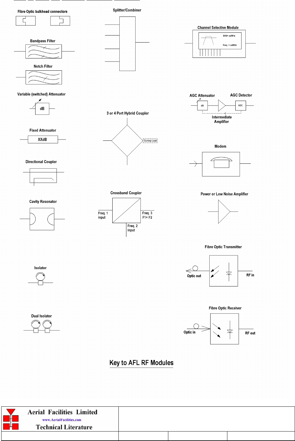
Key to AFL RF Module Drawing Symbols
Weehawken Tunnel Remote Repeater
User/Maintenance Handbook
Handbook Nō.-Weehawken_River_P Issue No:-A Date:-05/08/05 Page:-9 of 36
1. SAFETY CONSIDERATIONS
1.1 Earthing of Equipment
Cell Enhancers supplied from the mains must be connected to grounded outlets and earthed in
conformity with appropriate local, national and international electricity supply and safety
regulations.
1.2 Electric Shock Hazard
Electrical shocks due to faulty mains driven power supplies.
Whilst ever potentially present in any electrical equipment, such a condition would be
minimised by quality installation practice and thorough testing at:
a) Original assembly
b) Commissioning
c) Regular intervals, thereafter.
All test equipment to be in good working order prior to its use. High current power supplies can
be dangerous because of the possibility of substantial arcing. Always switch off during
disconnection and reconnection.
Weehawken Tunnel Remote Repeater
User/Maintenance Handbook
Handbook Nō.-Weehawken_River_P Issue No:-A Date:-05/08/05 Page:-10 of 36
1.3 RF Radiation Hazard
RF radiation, (especially at UHF frequencies) arising from transmitter outputs connected to
AFL’s equipment, must be considered a safety hazard.
This condition might only occur in the event of cable disconnection, or because a ‘spare’ output
has been left unterminated. Either of these conditions would impair the system’s efficiency. No
investigation should be carried out until all RF power sources have been removed. This would
always be a wise precaution, despite the severe mismatch between the impedance of an N type
connector at 50Ω, and that of free space at 377Ω, which would severely mitigate against the
efficient radiation of RF power. Radio frequency burns could also be a hazard, if any RF power
carrying components were to be carelessly touched!
Antenna positions should be chosen to comply with requirements (both local & statutory)
regarding exposure of personnel to RF radiation. When connected to an antenna, the unit is
capable of producing RF field strengths, which may exceed guideline safe values especially if
used with antennas having appreciable gain. In this regard the use of directional antennas with
backscreens and a strict site rule that personnel must remain behind the screen while the RF
power is on, is strongly recommended.
Where the equipment is used near power lines, or in association with temporary masts not
having lightning protection, the use of a safety earth connected to the case-earthing bolt is
strongly advised.
Weehawken Tunnel Remote Repeater
User/Maintenance Handbook
Handbook Nō.-Weehawken_River_P Issue No:-A Date:-05/08/05 Page:-11 of 36
1.4 Chemical Hazard
Beryllium Oxide, also known as Beryllium Monoxide, or Thermalox™, is sometimes used in
devices within equipment produced by Aerial Facilities Ltd. Beryllium oxide dust can be toxic if
inhaled, leading to chronic respiratory problems. It is harmless if ingested or by contact.
Products that contain beryllium are load terminations (dummy loads) and some power
amplifiers. These products can be identified by a yellow and black “skull and crossbones”
danger symbol (shown above). They are marked as hazardous in line with international
regulations, but pose no threat under normal circumstances. Only if a component containing
beryllium oxide has suffered catastrophic failure, or exploded, will there be any danger of the
formation of dust. Any dust that has been created will be contained within the equipment
module as long as the module remains sealed. For this reason, any module carrying the yellow
and black danger sign should not be opened. If the equipment is suspected of failure, or is at the
end of its life-cycle, it must be returned to Aerial Facilities Ltd for disposal.
To return such equipment, please contact the Quality Department, who will give you a Returned
Materials Authorisation (RMA) number. Please quote this number on the packing documents,
and on all correspondence relating to the shipment.
PolyTetraFluoroEthylene, (P.T.F.E.) and P.T.F.E. Composite Materials
Many modules/components in AFL equipment contain P.T.F.E. as part of the RF insulation
barrier.
This material should never be heated to the point where smoke or fumes are evolved. Any
person feeling drowsy after coming into contact with P.T.F.E. especially dust or fumes should
seek medical attention.
1.5 Emergency Contact Numbers
The AFL Quality Department can be contacted on:
Telephone +44 (0)1494 777000
Fax +44 (0)1494 777002
e-mail qa@aerial.co.uk

Weehawken Tunnel Remote Repeater
User/Maintenance Handbook
Handbook Nō.-Weehawken_River_P Issue No:-A Date:-05/08/05 Page:-12 of 36
2. OVERVIEW/ SYSTEM DESCRIPTION
2.1 General System Description
The Weehawken tunnel radio system is designed to amplify various bands of radio frequencies,
in either channelised or band selective modes. This unit amplifies all the RF bands to the ‘River
Portal’ area in a band-selective mode with AGC in the uplink direction. All the hardware is
built into a standard environmentally protected cabinet which has an IP rating of 65.
The system described in this document is ‘stand-alone’ and needs no other equipment apart
from a +12V DC power supply. Every active module in the entire system has a dedicated alarm
and these are series wired within the unit to a relay which gives a volt-free output pair which is
wired to a ‘krone-block’ termination and ultimately to a pair of wires in an external port
connector (alarm connector, pins 1 & 2).
Weehawken Tunnel Remote Repeater
User/Maintenance Handbook
Handbook Nō.-Weehawken_River_P Issue No:-A Date:-05/08/05 Page:-13 of 36
3. MULTI-BAND SELECTIVE CELL ENHANCER (RIVER PORTAL)
3.3 Band Selective BDA (55-154901)
3.3.1 Band Selective BDA Description
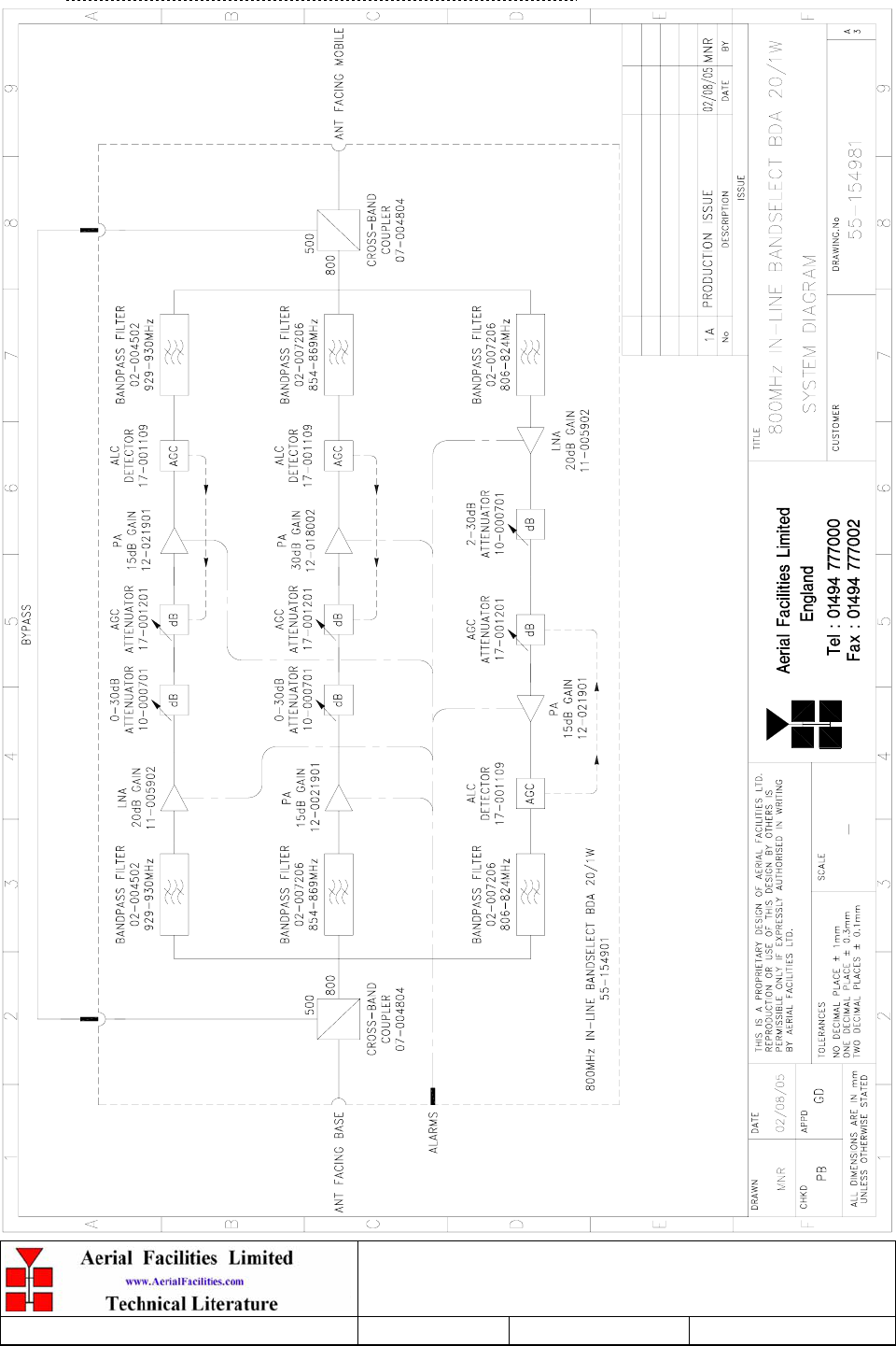
The band selective BDA which covers the ‘River Portal’ site carries two downlink paths and
one uplink path, all with automatic gain control on the last amplification stage in each path.
Cross band couplers are fitted to the input and output to facilitate a low frequency bypass of
the 800MHz BDA allowing the lower frequency signals to pass unhindered.
All amplifiers have built-in alarms which are configured as a summary, volt-free relay
contact pair terminating at pins 1 & 2 on the ‘D’ type alarm connector.
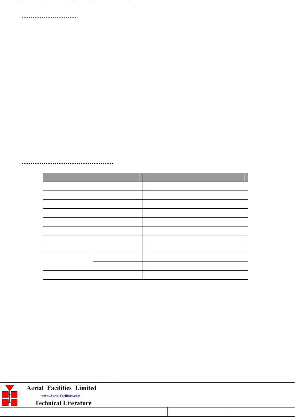
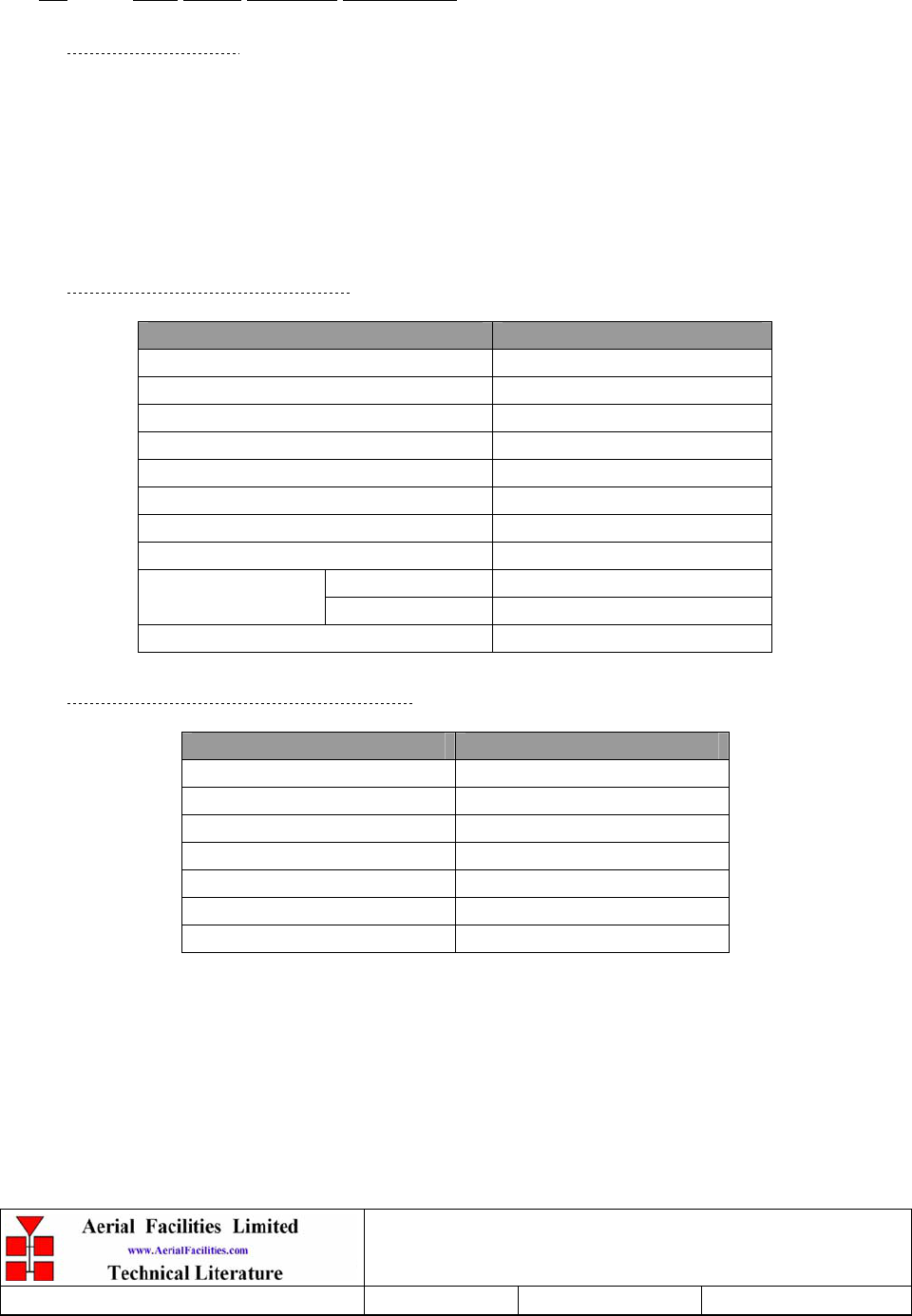
3.3.2 Band Selective BDA Electrical Specification
PARAMETER SPECIFICATION
929-930MHz (Downlink)
854-869MHz (Downlink)
Frequency ranges:
806-824MHz (Uplink)
Gain: >35dB
Gain Adjustment: 0 - 30dB (in 2dB steps)
Uplink power: >1.0Watts (806-824MHz path)
Downlink power: >1.0Watts (929-930MHz path)
Downlink power: >20.0Watts (854-869MHz path)
Uplink +43dBm (806-824 & 929-930MHz paths)
IP3: Downlink +56dBm (854-869MHz path)
Noise Figure: <6dB (at maximum gain)
AGC: Fitted to all paths
DC Power supply: 12V DC (externally supplied)
VSWR: better than 1.5:1
RF Connectors: N type, female
operational: -10°C to +55°C
Temperature range: storage: -40°C to +70°C
1 Downlink amplifiers Alarms Fitted:
(volt-free contacts/TTL) 2 Uplink amplifiers

Weehawken Tunnel Remote Repeater
User/Maintenance Handbook
Handbook Nō.-Weehawken_River_P Issue No:-A Date:-05/08/05 Page:-14 of 36
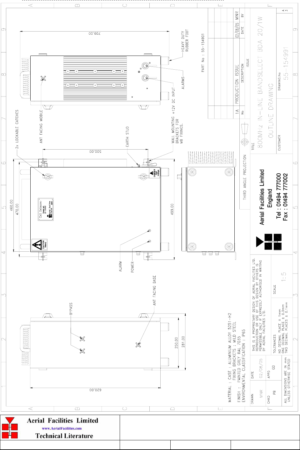
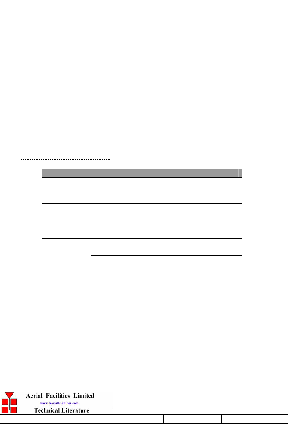
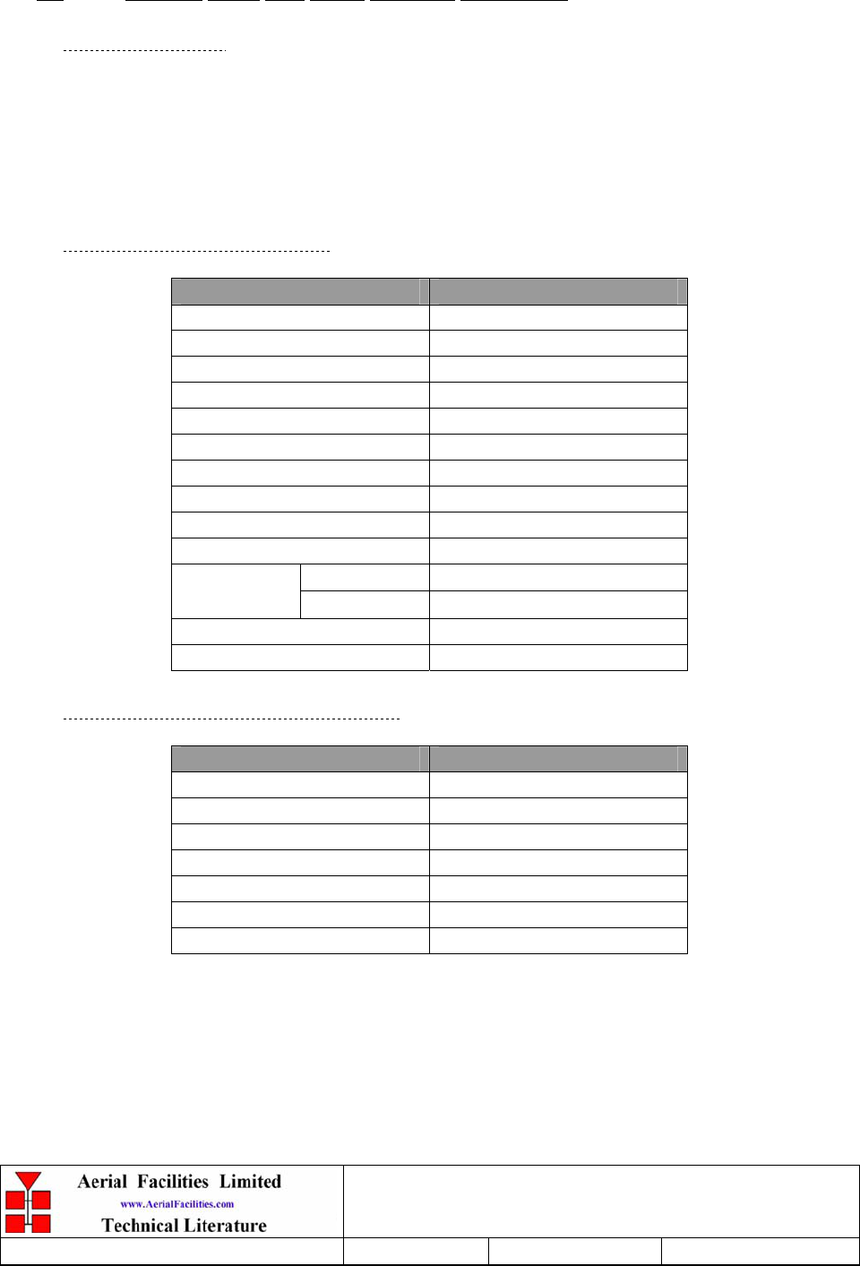
3.3.3 Band Selective BDA Mechanical Specification
PARAMETER SPECIFICATION
Height: 620mm
Width: 620mm
Case size
Depth: 250mm
(excluding heatsinks, connectors, handles and feet)
Fixings: 4 holes on 670(w) x 558(h)mm
Operational: -10°C to +55°C
Temperature range: Storage: -40°C to +70°C
Weight: >30kg
RF Connectors: N type female
Environmental Protection: IP65 (with door closed and all ports terminated)
Case: To RAL 7035
Heatsinks: Matt black (where fitted)
Finish:
Handles: Black technopolymer
Supply Cable: Unit supplied with suitable supply input leads with
connector and appropriate length of cable
Weehawken Tunnel Remote Repeater
User/Maintenance Handbook
Handbook Nō.-Weehawken_River_P Issue No:-A Date:-05/08/05 Page:-15 of 36
3.3.4 Band Selective BDA System Diagram 55-154981
Weehawken Tunnel Remote Repeater
User/Maintenance Handbook
Handbook Nō.-Weehawken_River_P Issue No:-A Date:-05/08/05 Page:-16 of 36
3.3.5 Band Selective BDA Outline Drawing, Drg. Nō. 50-118181

Weehawken Tunnel Remote Repeater
User/Maintenance Handbook
Handbook Nō.-Weehawken_River_P Issue No:-A Date:-05/08/05 Page:-17 of 36
3.3.6 Weehawken System Frequencies Look-up Table
Agency Channel
Number Uplink Tx Downlink Rx
Jersey City Medical Center - EMS VHF CHN 1 153.7850 153.7850
North Hudson Regional Fire and Rescue VHF CHN 2 154.3250 154.3250
NJ Statewide Police (SPEN) VHF CHN 3 154.6800 154.6800
Jersey City Medical Center - EMS VHF CHN 4 155.2350 155.2350
Jersey City Medical Center - EMS VHF CHN 5 155.2800 155.2800
North Hudson Regional Fire and Rescue VHF CHN 6 158.8650 154.1450
Weehawken Township VHF CHN 7 159.0900 159.0900
Weehawken Township VHF CHN 8 159.2100 159.2100
New Jersey Transit Police Dept. VHF CHN 9 161.5200 160.8300
Jersey City Police Department UHF CHN 1 465.3750 460.3750
Jersey City Fire Department UHF CHN 2 465.5500 460.5500
Jersey City Fire Department UHF CHN 3 465.6000 460.6000
Hoboken Fire Dept UHF CHN 4 471.5500 471.5500
West New York Police Department UHF CHN 5 473.3125 470.3125
New Jersey Transit Bus Data System 800 CHN 1 809.2875 854.2875
New Jersey Transit Bus Data System 800 CHN 2 809.4875 854.4875
Township of North Bergen Police 800 CHN 3 810.7375 855.7375
City of Union City 800 CHN 4 821.3500 866.3500
New Jersey Transit Trunked Radio System 800 CHN 5 821.4625 866.4625
New Jersey Transit Trunked Radio System 800 CHN 6 821.4875 866.4875
New Jersey Transit Trunked Radio System 800 CHN 7 821.9625 866.9625
New Jersey Transit Trunked Radio System 800 CHN 8 821.9875 866.9875
City of Union City 800 CHN 9 822.1625 867.1625
New Jersey Transit Trunked Radio System 800 CHN 10 822.4625 867.4625
New Jersey Transit Trunked Radio System 800 CHN 11 822.4875 867.4875
New Jersey Transit Trunked Radio System 800 CHN 12 822.9625 867.9625
New Jersey Transit Trunked Radio System 800 CHN 13 822.9875 867.9875
City of Union City 800 CHN 14 823.1875 868.1875
City of Union City 800 CHN 15 823.2125 868.2125
New Jersey Transit Trunked Radio System 800 CHN 16 823.4625 868.4625
New Jersey Transit Trunked Radio System 800 CHN 17 823.4875 868.4875
New Jersey Transit Paging 900 CHN 1 929.5875
New Jersey Transit Paging 900 CHN 2 929.6125

Weehawken Tunnel Remote Repeater
User/Maintenance Handbook
Handbook Nō.-Weehawken_River_P Issue No:-A Date:-05/08/05 Page:-18 of 36
3.3.7 Band Selective BDA (55-154901) Parts List
AFL Part Nō. Part Description Qty.
02-004502 4P C/L SD FILTER 920MHz (3MHz B/W) SMA 2
02-007206 900MHz 8POLE 15-25MHz B/W "SMA" 4
07-005705 CROSSBAND CPLR XC 250/380 SMA 2
10-000701 1/4W0-30dB SWITCHED ATTENUATOR 3
11-005902 900MHz LOW NOISE AMP WITH RELAY ASS 2
12-018002 PA 800-960MHz 20W CLASS A 1
12-021901 POWER AMPLIFIER 900MHz 1W +12V 3
17-000126 CELL ENHANCER LABEL 6 DIGIT 1
17-000526 CE 10W HEATSINK THERMAL GASKET 2
17-001109 CE AGC UNIT LOG DET/AMP ASSY (12V) 3
17-001201 C/E AGC UNIT ATTENUATOR ASSY 3
17-001527 C/E HS 2.00mm ALUM BLANKING PLATE 1
17-001528 GASKET 20W HEATSINK/BLANKING PLATE 1
17-009020 ENCLOSURE 620 x 420 x 250 (3 H/S) ALU 1
80-008901 12V RELAY PCB ASSEMBLY 1
80-031820 20W PA HEATSINK 1
80-032320 10W PA HEATSINK 1
80-122701 BBU to CE DC CABLE, 2pole IP68 BULGIN 1
91-030002 N ADAPTOR PANEL FEMALE:FEMALE 2
91-130001 SMA ADAPT 'T' ALL FEMALE 3 GHz 4
91-500013 PWR 2POLE PNL PLUG SEALED IP68 1
91-500015 PWR CON CAP SEALED with INT. THREAD 2
91-500016 PWR 6POLE PNL PLUG SEALED IP68 1
91-510032 20A SOCKET CONTACT PIN 2
91-600007 'D' 9 WAY BLACK SHELL 5
91-600014 'D' 9 WAY SOCKET S/B (NON FILTERED) 5
91-660001 2W5 MIXED D TYPE SOCKET (7 WAY) 1
91-700017 ICD 15 WAY 0.1' CONNECTOR 1
96-700034 LED RED 5mm IP67 1
96-700035 LED GREEN 5mm IP67 1
97-400010 BLACK PLASTIC HANDLE 50mm HIGH 2
97-900003 RUBBER FOOT 1 1:2' DIA. 4
Weehawken Tunnel Remote Repeater
User/Maintenance Handbook
Handbook Nō.-Weehawken_River_P Issue No:-A Date:-05/08/05 Page:-19 of 36
4. ALARMS
4.1 Alarm/Monitor System
4.1.1 Alarm/Monitor Description
The alarm system acts as an alarm concentrator for all the alarms in the unit. Firstly, within
each active component, the individually alarmed modules are ‘summed together’ and
presented to the outside world as a volt-free, relay contact pair (pins 1 & 2 in the IP65 alarm
connector.
As all the alarms in the system are ‘held closed loops’, should the power supply fail, the
main system alarm will be triggered.
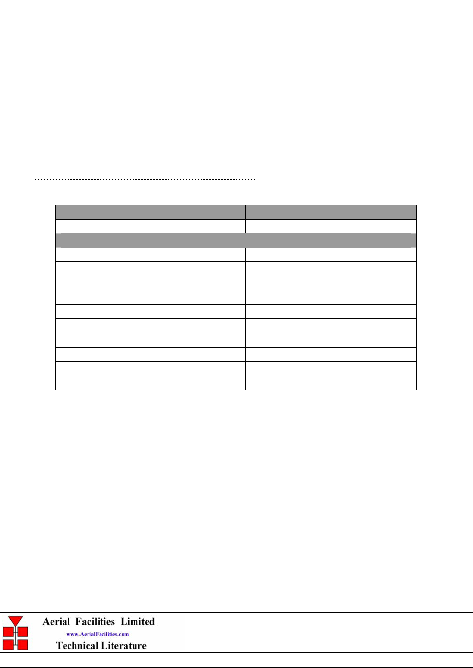
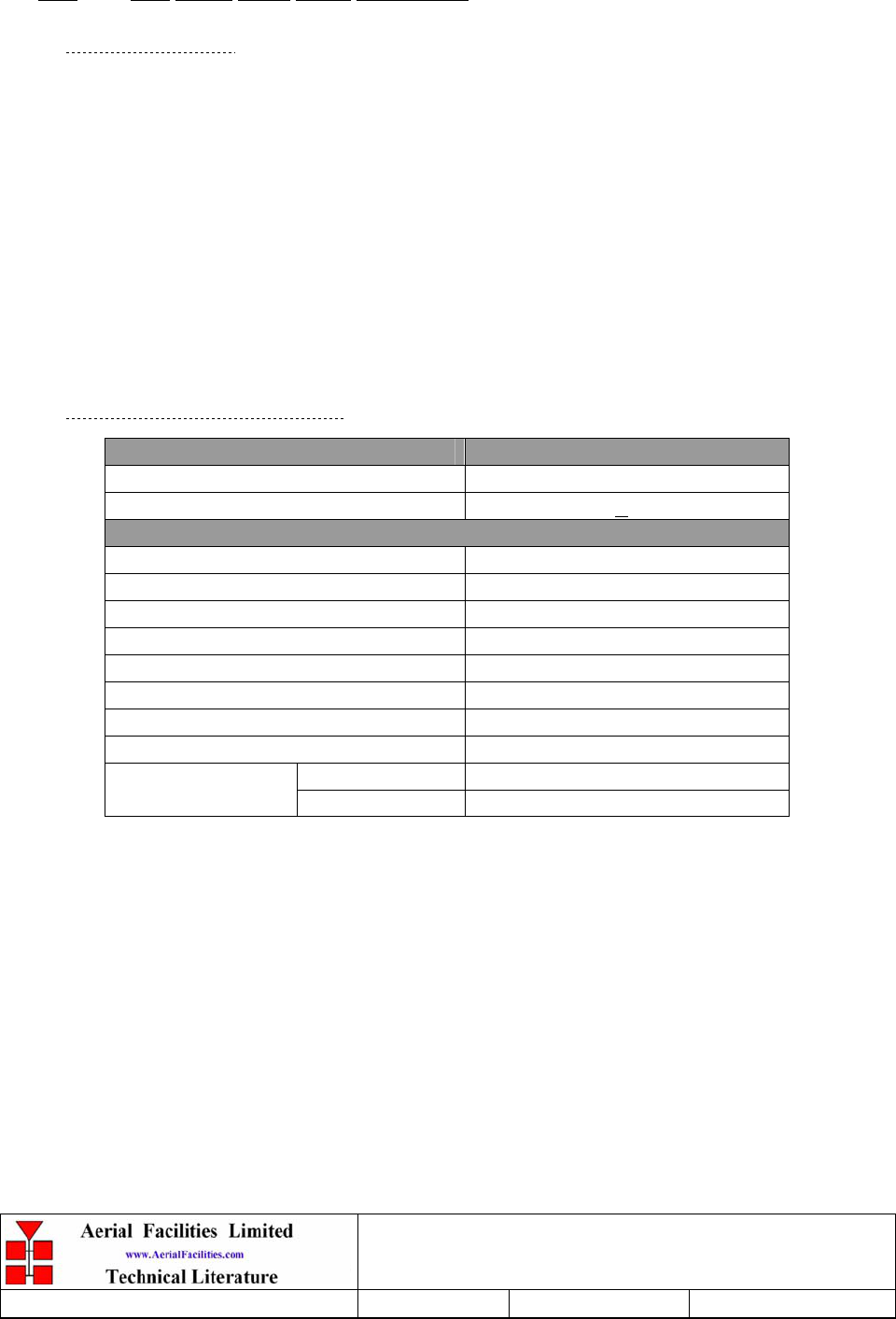
4.1.2 Alarm/Monitor Technical Specification
PARAMETER SPECIFICATION
Operating voltage: 12V (floating earth)
Alarm output relay contacts:
Max. switch current: 1.0Amp
Max. switch volts: 120Vdc/60VA
Max. switch power: 24W/60VA
Min. switch load: 10.0µA/10.0mV
Relay isolation: 1.5kV
Mechanical life: >2x10⁷ operations
Relay approval: BT type 56
Connector details: 25 Way ‘D’ Connector
operational: :-10°C to +55°C
Temperature range storage: :-40°C to +70°C
Weehawken Tunnel Remote Repeater
User/Maintenance Handbook
Handbook Nō.-Weehawken_River_P Issue No:-A Date:-05/08/05 Page:-20 of 36
5. SUB-UNIT MODULES
5.1 Bandpass Filter (02-004502)
5.1.1 Description
The bandpass filters are multi-section designs with a bandwidth dependent upon the passband
frequencies, (both tuned to customer requirements). The response shape is basically Chebyshev
with a passband design ripple of 0.1dB. The filters are of slot coupled, folded combline design,
and are carefully aligned during manufacture in order to optimise the insertion loss, VSWR and
intermodulation characteristics of the unit. The tuned elements are silver-plated to reduce
surface ohmic losses and maintain a good VSWR figure and 50Ω load at the input and output
ports.
Being passive devices, the bandpass filters should have an extremely long operational life and
require no maintenance. Should a filter be suspect, it is usually most time efficient to replace
the module rather than attempt repair or re-tuning.
No adjustments should be attempted without full network sweep analysis facilities to monitor
both insertion loss and VSWR simultaneously.
5.1.2 Technical Specification
PARAMETER SPECIFICATION
Response Type Chebyshev
Frequency Range: 751-862MHz (tuned to spec.)
Bandwidth: 12MHz (tuned to spec.)
Number of Sections: 5
Insertion Loss: 1.2 dB
VSWR: better than 1.2:1
Connectors: SMA female
Power Handling: 100W max
operation: -10°C to +60°C Temperature
range: storage: -20°C to +70°C
Weight: 3 kg (typical)
Weehawken Tunnel Remote Repeater
User/Maintenance Handbook
Handbook Nō.-Weehawken_River_P Issue No:-A Date:-05/08/05 Page:-21 of 36
5.2 Bandpass Filter (02-007206)
5.2.1 Description
The bandpass filters are multi-section designs with a bandwidth dependent upon the passband
frequencies, (both tuned to customer requirements). The response shape is basically Chebyshev
with a passband design ripple of 0.1dB. The filters are of slot coupled, folded combline design,
and are carefully aligned during manufacture in order to optimise the insertion loss, VSWR and
intermodulation characteristics of the unit. The tuned elements are silver-plated to reduce
surface ohmic losses and maintain a good VSWR figure and 50Ω load at the input and output
ports.
Being passive devices, the bandpass filters should have an extremely long operational life and
require no maintenance. Should a filter be suspect, it is usually most time efficient to replace
the module rather than attempt repair or re-tuning.
No adjustments should be attempted without full network sweep analysis facilities to monitor
both insertion loss and VSWR simultaneously.
5.2.2 Technical Specification
PARAMETER SPECIFICATION
Response Type Chebyshev
Frequency range: 800 - 950MHz (tuned to spec.)
Bandwidth: 25MHz (tuned to spec.)
Number of sections: 8
Insertion Loss: 1.2 dB
VSWR: better than 1.2:1
Connectors: SMA female
Power Handling: 100W max
operation: -10°C to +60°C Temperature
range: storage: -20°C to +70°C
Weight: 3 kg (typical)
Weehawken Tunnel Remote Repeater
User/Maintenance Handbook
Handbook Nō.-Weehawken_River_P Issue No:-A Date:-05/08/05 Page:-22 of 36
5.3 Crossband Coupler (07-005705)
5.3.1 Description
The purpose of a crossband coupler is to either combine/split transmission signals from
different parts of the frequency spectrum.
It basically comprises of a 3 port device, two filters, one a low pass, the other a high pass
feeding a common output. In this case, a VHF spectrum signal source is to be combined with a
band 2 FM source, (many other combinations are also possible). The couplers are built into a
machined aluminium casing having a centre screening wall between the filter sections and lid
secured by screws at frequent intervals over its perimeter to obtain a tight seal and to ensure
linearity and stability of response.
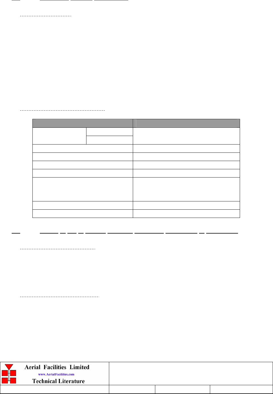
5.3.2 Technical Specification
PARAMETER SPECIFICATION
250 MHz:
Passband 380 MHz:
70-250MHz
380-960 MHz
Power Rating: 50 Watts (CW)
Number of Input ports: 2
Number of Output ports: 1
Insertion loss: 0.5 dB
Isolation:
> 50 dB 70-250MHz
> 50 dB 380-960MHz
(15 dB typical Return loss 500-960)
Impedance: 50 ohm
Connectors: SMA- female
5.4 ¼Watt 0- -30 & 0-15dB Switched Attenuator (10-000701 & 10-000901)
5.4.1 General Application
In many practical applications for Cell Enhancers etc., the gain in each path is found to be
excessive. Therefore, provision is made within the unit for the setting of attenuation in each
path, to reduce the gain.
5.4.2 Switched Attenuators
The AFL switched attenuators are available in two different types; 0 – 30dB in 2 dB steps, or 0
– 15dB in 1 dB steps. The attenuation is simply set using the four miniature toggle switches on
the top of each unit. Each switch is clearly marked with the attenuation it provides, and the total
attenuation in line is the sum of the values switched in. They are designed to maintain an
accurate 50Ω impedance over their operating frequency at both input and output.

Weehawken Tunnel Remote Repeater
User/Maintenance Handbook
Handbook Nō.-Weehawken_River_P Issue No:-A Date:-05/08/05 Page:-23 of 36
5.5 Low Noise Amplifier (11-005902)
5.5.1 Description
The Gallium-Arsenide low noise amplifier used in the unit is a double stage, solid-state low
noise amplifier. Class A circuitry is used throughout the units to ensure excellent linearity and
extremely low noise over a very wide dynamic range. The active devices are very moderately
rated to provide a long trouble-free working life. There are no adjustments on these amplifiers,
and in the unlikely event of a failure, then the complete amplifier should be replaced. This
amplifier features its own in-built alarm system which gives a volt-free relay contact type alarm
that is easily integrated into the main alarm system.
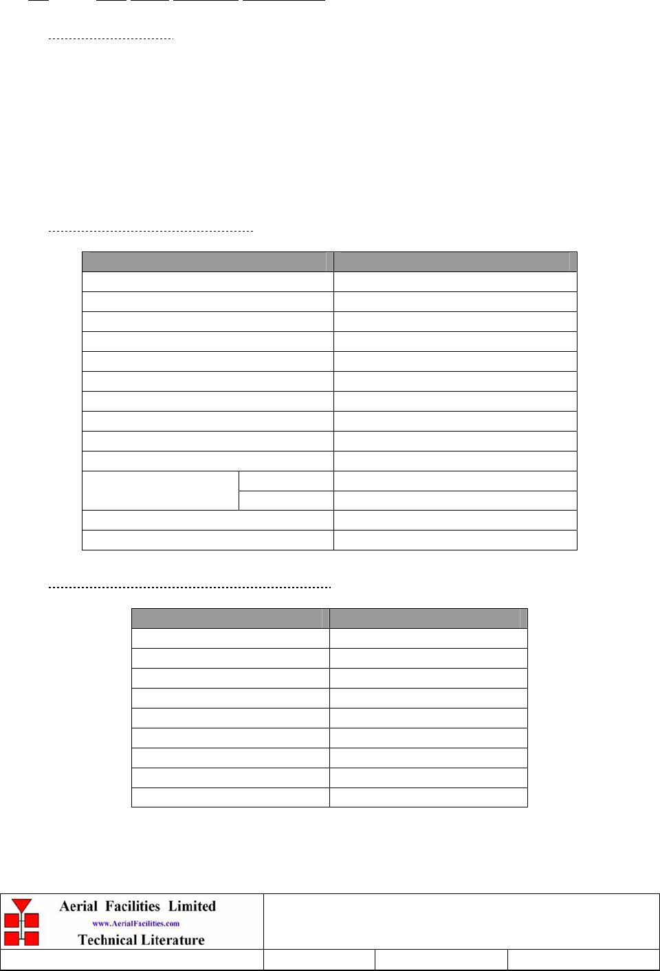
5.5.2 Technical Specification
PARAMETER SPECIFICATION
Frequency range: 800 – 960MHz
Bandwidth: <170MHz
Gain: 19.5dB (typical)
1dB Compression point: 21dBm
OIP3: 33dBm
Input/Output Return Loss: >20dB
Noise Figure: 1dB (typical)
Power consumption: 190mA @ 24V DC
Supply voltage: 10-24V DC
Connectors: SMA female
operational: -10°C to +60°C
Temperature range: storage: -20°C to +70°C
Size: 90 x 55 x 30.2mm
Weight: 0.28kg
Weehawken Tunnel Remote Repeater
User/Maintenance Handbook
Handbook Nō.-Weehawken_River_P Issue No:-A Date:-05/08/05 Page:-24 of 36
5.6 Low Noise Amplifier (11-006702)
5.6.1 Description
The Gallium-Arsenide low noise amplifiers used in the system are double stage, solid-state
low noise amplifiers. Class A circuitry is used throughout the units to ensure excellent
linearity and extremely low noise over a very wide dynamic range. The active devices are
very moderately rated to provide a long trouble-free working life. There are no adjustments
on these amplifiers, and in the unlikely event of a failure, then the complete amplifier should
be replaced. This amplifier features its own in-built alarm system which gives a volt-free
relay contact type alarm that is easily integrated into the main alarm system.
5.6.2 Technical Specification
PARAMETER SPECIFICATION
Frequency Range: 800 – 1000MHz
Bandwidth: <200MHz
Gain: 29dB (typical)
1dB Compression Point: 20dBm
OIP3: 33dBm
Input/Output Return Loss: >18dB
Noise Figure: 1.3dB (typical)
Power Consumption: 180mA @ 24V DC
Supply Voltage: 10-24V DC
Connectors: SMA female
operational: -10°C to +60°C
Temperature Range: storage: -20°C to +70°C
Size: 90 x 55 x 30.2mm
Weight: 290gms (approximately)
5.6.3 LNA ‘D’ Connector Pin-out details
Connector pin Signal
1 +Ve input (10-24V)
2 GND
3 Alarm Relay O/P bad
4 Alarm Relay common
5 Alarm Relay good
6 No connection
7 TTL voltage set
8 TTL alarm/0V (good)
9 O/C good/0V bad
Weehawken Tunnel Remote Repeater
User/Maintenance Handbook
Handbook Nō.-Weehawken_River_P Issue No:-A Date:-05/08/05 Page:-25 of 36
5.7 20W Power Amplifier (12-018002)
5.7.1 Description
This amplifier is a Class A 20W power amplifier from 800-960MHz in a 1 stage balanced
configuration. It demonstrates a very high linearity and a very good input/output return loss
(RL). It has built in a Current Fault Alarm Function.
Its housing is an aluminium case (Alocrom 1200 finish) with SMA connectors for the RF
input/output and a D-Type connector for the power supply and the Current Fault Alarm
Function.
5.7.2 Technical Specification
PARAMETER SPECIFICATION
Frequency range: 800-960MHz
Small signal gain: 30dB
Gain flatness: ±1.2dB
I/O Return loss: >18dB
1dB compression point: 42.8dBm
OIP3: 56dBm
Supply voltage: 24V DC
Supply current: 5.0Amps (Typical)
operational: -10°C to +60°C Temperature
range storage: -20°C to +70°C
Weight: <2kg (no heatsink)
5.7.3 PA 7-Way Connector Pin-outs
Connector Pin Signal
A1 (large pin) +24V DC
A2 (large pin) GND
1 Alarm relay common
2 TTL alarm/0V good
3 Alarm relay contact (bad)
4 Alarm relay contact (good)
5 O/C good/0V bad (TTL)
Weehawken Tunnel Remote Repeater
User/Maintenance Handbook
Handbook Nō.-Weehawken_River_P Issue No:-A Date:-05/08/05 Page:-26 of 36
5.8 800MHz 1Watt Low Power Amplifier (12-021901)
5.8.1 Description
The low power amplifier used is a triple stage solid-state low-noise amplifier. Class A circuitry
is used in the unit to ensure excellent linearity over a very wide dynamic range. The three active
devices are very moderately rated to provide a long trouble-free working life. There are no
adjustments on this amplifier, and in the unlikely event of failure then the entire amplifier
should be replaced.
5.8.2 Technical Specification
PARAMETER SPECIFICATION
Frequency range: 800-960MHz
Bandwidth: 20MHz (tuned to specificati
o
Maximum RF output: >1.0 Watt
Gain: 15dB
1dB compression point: +30.5dBm
3rd order intercept point: +43dBm
Noise Figure: <6dB
VSWR: better than 1.5:1
Connectors: SMA female
Supply: 500mA @ 10-15V DC
operational: -10°C to +60°C
Temperature
range: storage: -20°C to +70°C
Weight: 0.5 kg
Size: 167x52x25mm
5.8.3 LPA 7-Way Connector Pin-outs
Connector Pin Signal
A1 (large pin) +24V DC
A2 (large pin) GND
1 Alarm relay common
2 TTL alarm/0V good
3 Alarm relay contact (bad)
4 Alarm relay contact (good)
5 O/C good/0V bad (TTL)

Weehawken Tunnel Remote Repeater
User/Maintenance Handbook
Handbook Nō.-Weehawken_River_P Issue No:-A Date:-05/08/05 Page:-27 of 36
5.9 Wide Dynamic Range AGC (17-001109, det. & 17-001201, atten.)
5.9.1 Description
The equipment is fitted with a wide dynamic range Automatic Gain Control (AGC) system.
This is generally fitted in the Uplink path (not usually needed in the downlink path, as the
signal here is at an almost constant level), to avoid overloading the amplifiers (with the
associated performance degradation) should a mobile be operated very close to the unit.
The AFL wide dynamic range Automatic Gain Control system consists of two units, a
detector/amplifier and an attenuator. The logarithmic detector/amplifier unit is inserted in the
RF path on the output of the power amplifier, and the attenuator is situated in the RF path
between the 1st and 2nd stages of amplification.
Normally the attenuator is at minimum attenuation. The detector/amplifier unit monitors the RF
level being delivered by the power amplifier, and when a certain threshold is reached it begins
to increase the value of the attenuator to limit the RF output to the (factory set) threshold.
Therefore overloading of the power amplifier is avoided.
The factory set threshold is 1dB below the Enhancer 1dB compression point. Some adjustment
of this AGC threshold level is possible, a 10dB range is mostly achieved. It is not
recommended under any circumstances to adjust the AGC threshold to a level greater than the
1dB compression point as system degradation will occur.
The detector comprises of a 50Ω transmission line with a resistive tap which samples a small
portion of the mainline power. The sampled signal is amplified and fed to a conventional half
wave diode rectifier, the output of which is a DC voltage proportional to the RF input signal.
This DC voltage is passed via an inverting DC amplifier with integrating characteristics, to the
output, which drives the attenuation control line of the corresponding AGC attenuator. This
unit is fitted at some earlier point in the RF circuit.
The unit contains a 12V DC regulator in the detector module, which supplies stabilised voltage
to the DC amplifier and via an external cableform to the AGC attenuator.

Weehawken Tunnel Remote Repeater
User/Maintenance Handbook
Handbook Nō.-Weehawken_River_P Issue No:-A Date:-05/08/05 Page:-28 of 36
For small signals, below AGC onset, the output control line will be close to 12V and the AGC
attenuator will have minimum attenuation. As the signal level increases the control line voltage
will fall, increasing the attenuator value and keeping the system output level at a constant
value.
The AGC onset level is adjusted by the choice of sampler resistor R1 and by the setting of
potentiometer VR1, (factory set @ time of system test) do not adjust unless able to monitor
subsequent RF levels.
The attenuator comprises a 50Ω P.I.N diode, voltage-variable attenuator with a range of 3 to
30dB. The attenuation is controlled by a DC voltage which is derived from the associated AGC
detector unit.
5.9.2 Technical Specification
PARAMETER SPECIFICATION
Frequency range: up to 1000MHz
Attenuation range: 3 to 30dB
Attenuation steps: continuously variable
VSWR: better than 1.2:1
RF Connectors: SMA female
attenuator: 1W
Power handling: detector/amp: >30W (or as required)
operation: -10°C to +60°C
Temperature range: storage: -20°C to +70°C
attenuator pcb 50 x 42 x 21mm
Size: detector/amp pcb 54 x 42 x 21mm
attenuator: 90gm
Weight: detector/amp: 100gm
Weehawken Tunnel Remote Repeater
User/Maintenance Handbook
Handbook Nō.-Weehawken_River_P Issue No:-A Date:-05/08/05 Page:-29 of 36
5.10 12V Single Relay Board (80-008901)
5.10.1 Description
The General Purpose Relay Board allows the inversion of signals and the isolation of
circuits. It is equipped with a single dual pole change-over relay RL1, with completely
isolated wiring, accessed via a 15 way in-line connector.
The relay is provided with polarity protection diodes and diodes for suppressing the
transients caused by "flywheel effect" which can destroy switching transistors or induce
spikes on neighbouring circuits. It’s common use is to amalgamate all the alarm signals into
one, volts-free relay contact pair for the main alarm system.
Note that the board is available for different voltages (12 or 24V) depending on the type of
relay fitted at RL1.
5.10.2 Technical Specification
PARAMETER SPECIFICATION
Operating voltage: 8 to 30V (floating earth)
Alarm Threshold: Vcc - 1.20 volt +15%
Alarm output relay contacts:
Max. switch current: 1.0Amp
Max. switch volts: 120Vdc/60VA
Max. switch power: 24W/60VA
Min. switch load: 10.0µA/10.0mV
Relay isolation: 1.5kV
Mechanical life: >2x10⁷ operations
Relay approval: BT type 56
Connector details: Screw terminals
operational: :-10°C to +55°C
Temperature range storage: :-40°C to +70°C

Weehawken Tunnel Remote Repeater
User/Maintenance Handbook
Handbook Nō.-Weehawken_River_P Issue No:-A Date:-05/08/05 Page:-30 of 36
6. INSTALLATION
6.1 Wall Mounted Equipment
The procedure for installing and commissioning a wall-mounted Bi-Directional Amplifier unit
is generally as follows:
1 Fix the unit in the chosen position. Ensure the mounting site is a straight, smooth,
perpendicular surface (brick or concrete recommended).
2 Fix the two antennas and connect them to the BDA.
3 Connect a suitable mains and/or battery power supply to the unit.
4 Calculate the attenuation settings required for the uplink and the downlink paths, and set the
attenuators as described elsewhere in this document.
5 Switch the BDA mains on with the small switch located inside the unit on the lower right
hand side of the case.
6 Make test calls via the equipment to ensure correct operation, if possible monitoring the
signal levels during these calls to ensure that the uplink and downlink RF levels are as
anticipated.

Weehawken Tunnel Remote Repeater
User/Maintenance Handbook
Handbook Nō.-Weehawken_River_P Issue No:-A Date:-05/08/05 Page:-31 of 36
7. MAINTENANCE
7.1 Fault Finding
7.1.1 Quick Fault Checklist
All AFL equipment is individually tested to specification prior to despatch. Failure of this type
of equipment is not common. Experience has shown that a large number of fault conditions
relating to tunnel installations result from simple causes often occurring as result of
transportation, unpacking and installation. Below are listed some common problems which have
resulted in poor performance or an indicated non-functioning of the equipment.
• Mains power not connected or not switched on.
• External connectors not fitted or incorrectly fitted.
• Internal connectors becoming loose due to transport vibration.
• Wiring becoming detached as a result of heavy handling.
• Input signals not present due to faults in the aerial and feeder system.
• Base transmissions not present due to fault at the base station.
• Modems fitted with incorrect software configuration.
• Changes to channel frequencies and inhibiting channels.
• Hand held radio equipment not set to repeater channels.
• Hand held radio equipment not set to correct base station.
7.1.2 Fault Isolation
In the event that the performance of the system is suspect, a methodical and logical approach to
the problem will reveal the cause of the difficulty. The System consists of modules fitted in a
wall-mounted, environmentally protected enclosure.
Transmissions from the main base stations are passed though the system to the mobile radio
equipment; this could be a handheld radio or a transceiver in a vehicle. This path is referred to
as the downlink. The return signal path from the mobile radio equipment to the base station is
referred to as the uplink.
The first operation is to check the alarms of each of the active units and determine that the
power supplies to the equipment are connected and active.
This can be achieved remotely (via CEMS, the RS232 Coverage Enhancement Management
System, if fitted), or locally with the front panel LED’s. The green LED on the front panel
should be illuminated, while the red alarm indicator should be off. If an Alarm is on, then that
individual module must be isolated and individually tested against the original test
specification.
The individual amplifier units within the shelf have a green LED showing through a hole in
their piggy-back alarm board, which is illuminated if the unit is working correctly. If an
amplifier is suspect, check the DC power supply to the unit. If no other fault is apparent use a
spectrum analyser to measure the incoming signal level at the input and then after reconnecting
the amplifier input, measure the output level. Consult with the system diagram to determine the
expected gain and compare result.
In the event that there are no alarms on and all units appear to be functioning it will be
necessary to test the system in a systematic manner to confirm correct operation.

Weehawken Tunnel Remote Repeater
User/Maintenance Handbook
Handbook Nō.-Weehawken_River_P Issue No:-A Date:-05/08/05 Page:-32 of 36
7.1.3 Downlink
Confirm that there is a signal at the expected frequency and strength from the base station. If
this is not present then the fault may lay outside the system. To confirm this, inject a downlink
frequency signal from a known source at the master site BTS input and check for output at the
remote site feeder output.
If a signal is not received at the output it will be necessary to follow the downlink path through
the system to find a point at which the signal is lost. The expected downlink output for the
given input can be found in the end-to-end test specification.
7.1.4 Uplink
Testing the uplink involves a similar procedure to the downlink except that the frequencies
used are those transmitted by the mobile equipment.
7.1.5 Checking service
Following the repair of any part of the system it is recommended that a full end-to-end test is
carried out in accordance with the test specification and that the coverage is checked by survey.
It is important to bear in mind that the system includes a radiating cable network and base
stations that may be faulty or may have been damaged.

Weehawken Tunnel Remote Repeater
User/Maintenance Handbook
Handbook Nō.-Weehawken_River_P Issue No:-A Date:-05/08/05 Page:-33 of 36
7.1.6 Fault repair
Once a faulty component has been identified, a decision must be made on the appropriate
course to carry out a repair. A competent engineer can quickly remedy typical faults such as
faulty connections or cables. The exceptions to this are cable assemblies connecting bandpass
filter assemblies that are manufactured to critical lengths to maintain a 50-ohm system. Care
should be taken when replacing cables or connectors to ensure that items are of the correct
specification. The repair of component modules such as amplifiers and bandpass filters will not
usually be possible in the field, as they frequently require specialist knowledge and test
equipment to ensure correct operation. It is recommended that items of this type are replaced
with a spare unit and the faulty unit returned to AFL for repair.
7.1.7 Service Support
Advice and assistance with maintaining and servicing this system are available by contacting
Aerial Facilities Ltd.
NOTE
Individual modules are not intended to be repaired on site and attempts at repair will
invalidate active warranties. Company policy is that individual modules should be
repaired by replacement. Aerial Facilities Ltd maintains a high level of stock of most
modules which can usually be despatched at short notice to support this policy.
7.2 Tools & Test Equipment
The minimum tools and test equipment needed to successfully service this AFL product are as
follows:-
Spectrum analyser: 100kHz to 2GHz (Dynamic range = 90dB).
Signal Generator: 30MHz to 2GHz (-120dBm to 0dBm o/p level).
Attenuator: 20dB, 10W, DC-2GHz, (N male – N female).
Test Antenna: Yagi or dipole for operating frequency.
Digital multi-meter: Universal Volt-Ohm-Amp meter.
Test cable x 2: N male – N male, 2M long RG214.
Test cable x 2: SMA male – N male, 1m long RG223.
Hand tools: Philips #1&2 tip screwdriver.
3mm flat bladed screwdriver.
SMA spanner and torque setter.

Weehawken Tunnel Remote Repeater
User/Maintenance Handbook
Handbook Nō.-Weehawken_River_P Issue No:-A Date:-05/08/05 Page:-34 of 36
7.3 Care of Modules
7.3.1 General Comments
Many of the active modules contain semiconductor devices utilising MOS technology, which
can be damaged by electrostatic discharge. Correct handling of such modules is mandatory to
ensure their long-term reliability.
To prevent damage to a module, it must be withdrawn/inserted with care. The module may have
connectors on its underside, which might not be visible to the service operative.
7.3.2 Module Removal (LNA’s, general procedure):
The following general instructions should be followed to remove a module:
1 Remove power to the unit
2 Remove all visible connectors (RF, DC & alarm)
3 Release module retaining screws.
4 Slowly but firmly, pull the module straight out of its position. Take care not to twist/turn the
module during withdrawal. (When the module is loose, care may be needed, as there may be
concealed connections underneath).
7.3.3 Module Replacement (general):
1 Carefully align the module into its location then slowly push the module directly straight
into its position, taking care not to twist/turn it during insertion.
2 Reconnect all connectors, RF, alarm, power etc.,(concealed connectors may have to be
connected first).
3 Replace retaining screws (if any).
4 Double-check all connections before applying power.
7.3.4 Power Amplifiers
1) Remove power to the unit. (Switch off @ mains/battery, or remove DC in connector)
2) Remove alarm wires from alarm screw terminal block or disconnect multi-way alarm
connector.
3) Carefully disconnect the RF input and output coaxial connectors (usually SMA)
If alarm board removal is not required, go to step 5.
4) There is (usually) a plate attached to the alarm board which fixes it to the amplifier, remove
its retaining screws and the alarm board can be withdrawn from the amplifier in its entirety.
On certain types of amplifier the alarm board is not mounted on a dedicated mounting plate;
in this case it will have to firstly be removed by unscrewing it from the mounting pillars, in
most cases, the pillars will not have not have to be removed before lifting the amplifier.

Weehawken Tunnel Remote Repeater
User/Maintenance Handbook
Handbook Nō.-Weehawken_River_P Issue No:-A Date:-05/08/05 Page:-35 of 36
5) If the amplifier to be removed has a heatsink attached, there may be several different ways it
can have been assembled. The most commonly used method, is screws through the front of
the heatsink to threaded screw holes (or nuts and bolts), into the amplifier within the main
case. If the heatsink is mounted on the rear of the main case (e.g., against a wall in the case
of wall mounted enclosures), then the fixing method for the heatsink will be from within the
case, (otherwise the enclosure would have to be removed from the wall in order to remove
the heatsink).
When the heatsink has been removed, the amplifier may be unscrewed from the main casing
by its four corner fixings and gently withdrawn.
Fitting a new power amplifier module will be the exact reverse of the above.
Note: Do not forget to apply fresh heatsink compound to the heatsink/main case joint
and also between the amplifier and the main case.
7.3.5 Low Power Amplifier Replacement
1 Disconnect the mains power supply and disconnect the 24V dc supply connector for the
LPA.
2 Disconnect the RF input and output cables from the LPA.
3 Disconnect the alarm connector.
4 Remove the alarm monitoring wires from (D type connector) pins 9 and 10.
5 Remove the LPA module by removing the four retaining screws, replace with a new LPA
module and secure it with the screws.
6 Connect the RF cables to the LPA input and output connectors. Reconnect the wires to the
alarm board connector pins 9 and 10.
7 Reconnect the DC supply connector and turn the mains switch on.
Note: Tighten SMA connectors using only a dedicated SMA torque spanner. If SMA
connectors are over-tightened, irreparable damage will occur. . Do not use adjustable pliers
to loosen/tighten SMA connectors.
Also take care not to drop or knock the module as this can damage (or misalign in the case
of tuned passive modules) sensitive internal components. Always store the modules in an
environmentally friendly location
7.3.6 Module Transportation:
To maintain the operation, performance and reliability of any module it must be stored and
transported correctly. Any module not installed in a whole system must be kept in an anti-static
bag or container. These bags or containers are normally identified by being pink or black, and
are often marked with an ESD label. Any module sent back to AFL for investigation/repair must
be so protected. Please contact AFL’s quality department before returning a module.
Weehawken Tunnel Remote Repeater
User/Maintenance Handbook
Handbook Nō.-Weehawken_River_P Issue No:-A Date:-05/08/05 Page:-36 of 36
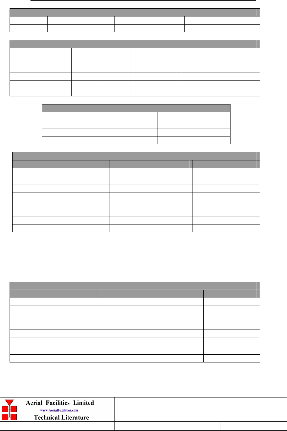
APPENDIX A INITIAL EQUIPMENT SET-UP CALCULATIONS
GENERAL INFORMATION
Site Name: Client Name:
Date: AFL Equip. Model Nō.
ANTENNA SYSTEMS
Model Gain Azimuth Comments
A - Service Antenna
B – Donor Antenna
Type Loss Length Comments
C – Service Feeder
D – Donor Feeder
INITIAL PARAMETERS
E – CE Output Power dBm
F – Antenna Isolation dB
G – Input signal level from donor BTS dBm
Operating Voltage V
DOWNLINK CALCULATIONS
Parameter Comments Value
Input signal level (G) dBm
CE max. o/p power (E) dBm
Gain setting E - G dB
Isolation required (Gain + 10dB) dB
Service antenna gain (A) dB
Service antenna feeder loss (C) dB
Effective radiated power (ERP) E+A-C dBm
Attenuator setting CE gain-gain setting dB
If the input signal level in the uplink path is known and steady, use the following calculation
table to determine the gain setting. If the CE features Automatic Gain Control the attenuator
should be set to zero and if not, then the attenuation setting for both uplink and downlink
should be similar.
UPLINK CALCULATIONS
Parameter Comments Value
Input signal level dBm
CE max. o/p power (E) dBm
Gain setting dB
Required isolation dB
Donor antenna gain (B) dB
Donor antenna feeder loss (D) dB
Effective radiated power (ERP) E+B-D dBm
Attenuator setting (CE gain-gain setting) dB