PBE Europe as Axell Wireless 60-0559SERIES UHF Signal Extender User Manual RECEIVER MULTICOUPLER
Axell Wireless UHF Signal Extender RECEIVER MULTICOUPLER
UserManual.wiki
>
PBE Europe as Axell Wireless
>
60 0559SERIES User Manual
handbook
Navigation menu
Upload a User Manual
Namespaces
Wiki Guide
HTML
PDF
Info
Views
User Manual
Discussion / Help
Navigation


![PBL UHF1/1A 1 & 2 Air InterfaceMaintenance HandbookH/book Number:-60-055900HBKM Issue No:-2 Date:-20/10/2003 Page:-14 of 8590-010022 RF CABLE SUPFLEX SMA R/A MALE 200mm 290-010026 RF CABLE HIFLEX SMA R/A MALE 150mm 690-010027 RF CABLE HIFLEX SMA R/A MALE 250mm 290-010028 RF CABLE HIFLEX SMA R/A MALE 350mm 190-010130 RF CABLE SMA R/A-N PANEL JACK 100mm 190-010131 RF CABLE SMA R/A-N PANEL JACK 200mm 390-010134 RF CABLE SMA R/A-N PANEL JACK 400mm 190-010135 RF CABLE SMA R/A-N PANEL JACK 500mm 291-030002 N ADAPTOR PANEL FEMALE:FEMALE 091-500011 PWR 3POLE PNL PLUG SEALED IP68 191-500015 PWR CON CAP SEALED with INT. THREAD 291-500016 PWR 6POLE PNL PLUG SEALED IP68 191-510010 PWR 3POLE FREE SOC.SEALED IP68 191-510013 PWR CON CAP SEALED with Ext. THREAD 291-510014 PWR 6POLE FREE SOC.SEALED IP68 191-600005 'D' 9 WAY SOCKET S/B TERM 091-600007 'D' 9 WAY BLACK SHELL 091-600014 'D' 9 WAY SOCKET S/B (NON FILTERED) 891-620002 'D' 25 WAY SOCKET/IDC TERMS 691-640003 MISC 26 WAY RIBBON CABLE SOCK. 691-700017 ICD 15 WAY 0.1' CONNECTOR 292-280033 Captive Screw 1292-400017 GASKET FOR N TYPE CONNECTOR 393-540035 1K3 0.25W 1% RES MRS25 M:F 293-930003 SMA COAX TERMINATION [RADIAL] 296-300011 24 V 400 W FLATPACK PWR SUPPLY 196-500003 AC FILTER 110V 5A 196-500005 DC INPUT FILTERS 196-700002 LED.GREEN 5mm SEALED IP66 196-700005 LED.RED 5mm SEALED IP66 196-900018 AC TRIP SWITCH (5 AMP M.C.B.) 196-920011 PROXIMITY SWITCH 196-920012 PROXIMITY SWITCH MAGNET 197-000002 BLACK MODULE CAGE RUNNER 1297-300010 SUPPLY I/P COVERS 197-400010 BLACK PLASTIC HANDLE 37311 297-600001 SUBRACK FRONT HORIZ 297-600002 SUBRACK M2.5 STD TAP 897-900004 RUBBER FOOT FOR CELL ENHANCERS 4](https://usermanual.wiki/PBE-Europe-as-Axell-Wireless/60-0559SERIES/User-Guide-366448-Page-14.png)
![PBL UHF1/1A 1 & 2 Air InterfaceMaintenance HandbookH/book Number:-60-055900HBKM Issue No:-2 Date:-20/10/2003 Page:-16 of 8591-030002 N ADAPTOR PANEL FEMALE:FEMALE 091-500011 PWR 3POLE PNL PLUG SEALED IP68 191-500015 PWR CON CAP SEALED with INT. THREAD 291-500016 PWR 6POLE PNL PLUG SEALED IP68 191-510010 PWR 3POLE FREE SOC.SEALED IP68 191-510013 PWR CON CAP SEALED with Ext. THREAD 291-510014 PWR 6POLE FREE SOC.SEALED IP68 191-600005 'D' 9 WAY SOCKET S/B TERM 091-600007 'D' 9 WAY BLACK SHELL 091-600014 'D' 9 WAY SOCKET S/B (NON FILTERED) 691-620002 'D' 25 WAY SOCKET/IDC TERMS 891-640003 MISC 26 WAY RIBBON CABLE SOCK. 891-700017 ICD 15 WAY 0.1' CONNECTOR 291-800014 3 WAY TERMINAL BLOCK 191-800019 OPTICAL BARREL ADAPT 492-120009 M20 IP68 CABLE GLAND 292-280033 Captive Screw 1692-400017 GASKET FOR N TYPE CONNECTOR 393-540035 1K3 0.25W 1% RES MRS25 M:F 293-930003 SMA COAX TERMINATION [RADIAL] 096-300011 24 V 400 W FLATPACK PWR SUPPLY 196-300045 JWS75-15/A PSU (COUTANT LAMBDA) 196-500003 AC FILTER 110V 5A 196-500005 DC INPUT FILTERS 196-700002 LED.GREEN 5mm SEALED IP66 196-700005 LED.RED 5mm SEALED IP66 196-900018 AC TRIP SWITCH (5 AMP M.C.B.) 196-920011 PROXIMITY SWITCH 196-920012 PROXIMITY SWITCH MAGNET 197-000002 BLACK MODULE CAGE RUNNER 1697-300010 SUPPLY I/P COVERS 197-400010 BLACK PLASTIC HANDLE 37311 297-600001 SUBRACK FRONT HORIZ 297-600002 SUBRACK M2.5 STD TAP 897-900004 RUBBER FOOT FOR CELL ENHANCERS 498-100001 1 x 2 SINGLE MODE OPTICAL COUPLR 1310 198-200003 FIBRE OPTIC Rx 6325 1310nm <2.2GHz 298-300003 FIBRE OPTIC Tx 6325 1310nm <2.2GHz 198-500004 FC/APC-FC/APC FIBREOPTIC CABLE 0.5M 2](https://usermanual.wiki/PBE-Europe-as-Axell-Wireless/60-0559SERIES/User-Guide-366448-Page-16.png)
![PBL UHF1/1A 1 & 2 Air InterfaceMaintenance HandbookH/book Number:-60-055900HBKM Issue No:-2 Date:-20/10/2003 Page:-17 of 853.1.1.3 F/O Air Interface 60-055903 Location ONE, UHF1A Parts ListAFL Part Nō.Part Description Qty.02-013401 6P CL FILTER (0.5 min BW)LARGE SMA ASSY 205-002603 UHF 3dB SPLITTER SMA 305-003401 4 WAY SPLITTER LOW POWER 410-000701 1/4W0-30dB SWITCHED ATTENUATOR 411-007402 LNA. 380-500MHz 30dB (C/W RELAY) GA 512-002201 3 STAGE AMPLIFIER ALARM BOARD 112-002220 3 STAGE ALARM PCB COVER 112-016301 PA 380-470MHz 20W CLASS A 113-003011 DC/DC CONVERTER 24-12V 8A PCB SUB-ASS 117-000126 CELL ENHANCER LABEL 6 DIGIT 117-002020 CASE 620 x 620 x 250 SCHROFF CUSTOM 117-003012 CHAN MOD 450MHz, 15kHz (8p) BW 617-003022 MODULE PATTERNED LEAVE 3217-003023 SUBRACK SIDE PANEL 417-003024 SUBRACK REAR BRACKET 3217-003025 BOTTOM MODULE GUIDE 1617-003028 MODULE SQUARE LEAVE 3217-003029 TOP MODULE GUIDE 1620-001602 24V RELAY BOARD 180-031820 20W PA HEATSINK (NEEDS 17-000526) 180-032320 10W PA HEATSINK (NEEDS 17-000526) 191-030002 N ADAPTOR PANEL FEMALE:FEMALE 391-500011 PWR 3POLE PNL PLUG SEALED IP68 191-500015 PWR CON CAP SEALED with INT. THREAD 291-500016 PWR 6POLE PNL PLUG SEALED IP68 191-600005 'D' 9 WAY SOCKET S/B TERM 691-600007 'D' 9 WAY BLACK SHELL 693-540035 1K3 0.25W 1% RES MRS25 M:F 193-930003 SMA COAX TERMINATION [RADIAL] 296-300011 24 V 400 W FLATPACK PWR SUPPLY 196-500005 DC INPUT FILTERS 196-700002 LED.GREEN 5mm SEALED IP66 196-700005 LED.RED 5mm SEALED IP66 196-920011 PROXIMITY SWITCH 196-920012 PROXIMITY SWITCH MAGNET 197-400010 BLACK PLASTIC HANDLE 37311 297-900004 RUBBER FOOT FOR CELL ENHANCERS 4](https://usermanual.wiki/PBE-Europe-as-Axell-Wireless/60-0559SERIES/User-Guide-366448-Page-17.png)
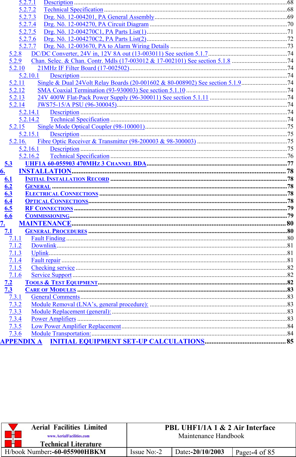
![PBL UHF1/1A 1 & 2 Air InterfaceMaintenance HandbookH/book Number:-60-055900HBKM Issue No:-2 Date:-20/10/2003 Page:-25 of 854. SYSTEM DRAWINGS4.1 Drg. Nō. 60-055990, Location ONE, UHF1/1A Case Outline DrawingBYDAT EDESCRIPT IO NNo123456789ABCDEF1 23456789ABCDEFFax : 01494 777002Tel : 01494 777000Aerial Facilities LimitedTHIS IS A PROPRIETARY DESIG N OF AERIAL FACIL ITIES L TD.REPRO DUCT IO N OR USE O F THIS DESIG N BY O THERS ISPERMISSIBL E O NL Y IF EXPRESSL Y AUTHO RISED IN WRITINGBY AERIAL FACIL ITIES LTD.NO DECIM AL PL ACE ± 1 mmO NE DECIM AL PL ACE ± 0 .3 mmTWO DECIMAL PLACES ± 0.1mmAL L DIMENSIO NS ARE IN mmUNLESS OTHERWISE STATEDCHKDDRAWN APPDDAT ETOLERANCES SCALEEnglandCUSTO MER DRAWING.NoTITLEISSUE3APASADENA BLUE LINE. LOCATION 1.UHF1OUTLINE DRAWING60-0559901A1:5DBS 15/10/02620 [2'-0.4"]E ngl andLi m i t edAerial FacilitiesUHF 1P rodu ct r ef :CE- / - NH eavyCAUTIONvol t ageHighDANGERTHIRD ANGLE PROJECTION700 [2'-3.6"]620 [2'-0.4"]250 [9.9"]709 [2'-3.9"]DOWNLINK INPUT/UPLINK OUTPUT UHF 1 (ANTENNA)UPLINK INPUT UHF 1P RODUCTION ISS UE15/10/02DBSM6 EARTH STUDDOWNLINK OUTPUT UHF 1115V AC INPUTPSU ALARM670 [2'-2.4"]555 [1'-9.9"]MATERIAL: MILD STEELFINISH: PAINTED TO RAL 9017 SEMI-GLOSS TRAFFIC B LACKWALL FIXINGS: M8 (5/16")RF CONNECTORS: N TYPE FEMALEENVIRONMENTAL CLASS: IP65DECIMAL EQUIV'S DBS21/10/021B2A ECN274630/10/02DBSALARMSPB GD](https://usermanual.wiki/PBE-Europe-as-Axell-Wireless/60-0559SERIES/User-Guide-366448-Page-25.png)
![PBL UHF1/1A 1 & 2 Air InterfaceMaintenance HandbookH/book Number:-60-055900HBKM Issue No:-2 Date:-20/10/2003 Page:-26 of 854.2 Drg. Nō. 60-055994 Location one, UHF1A (Upgrade) Case Outline DrawingPASADENA BLUE LINE. LOCATION 1.UHF1UPGRADE OUTLINE DRAWING60-0559921A1:5MNR 01/07/03BYDAT EDESCRIPT IO NNo123456789ABCDEF1 23456789ABCDEFFax : 01494 777002Tel : 01494 777000Aerial Facilities LimitedTHIS IS A PROPRIET ARY DESIG N O F AERIAL FACILITIES LTD.REPRO DUCTION O R USE OF THIS DESIGN BY OTHERS ISPERMISSIBLE ONLY IF EXPRESSL Y AUTHORISED IN WRITINGBY AERIAL FACILITIES LTD.NO DECIMAL PLACE ± 1 mmO NE DECIM A L PL ACE ± 0 .3 mmTWO DECIMAL PL ACES ± 0.1mmAL L DIMENSIONS ARE IN mmUNL ESS OTHERWISE STATEDCHKDDRAWN APPDDAT ET O L ERANCES SCAL EEnglandCUST O MER DRAWING .NoTITLEISSUE3A620 [2'-0.4"]E ngl andLi m i t edAerial FacilitiesUHF 1 AP r oduct r ef :CE- / - NHeavyCAUTIONvol t ageHighDANGERTHIRD ANGL E PRO JECTION700 [2'-3.6"]620 [2'-0.4"]250 [9.9"]709 [2'-3.9"]DOWNLINK INPUT/UPLINK OUTPUT (ANTENNA) (J7)INPUT FROM UHF 2 (Y)PRODUCTION ISSUE01/07/03MNRM6 EARTH STUDOUTPUT TO UHF 2 (Z)115V AC INPUTPSU ALARM670 [2'-2.4"]555 [1'-9.9"]MATERIAL: MILD STEELFINISH: PAINTED TO RAL 9017 SEMI-GLOSS TRAFFIC BLACKWALL FIXINGS: M8 (5/16")RF CONNECTORS: N TYPE FEMALEENVIRONMENTAL CLASS: IP65ALARMSUPLINK OUTPUT UHF 1 (W)DOWNLINK INPUT UHF 1 (X)OUTP UTTOUHF 1ANTENNA(X1)PB GD](https://usermanual.wiki/PBE-Europe-as-Axell-Wireless/60-0559SERIES/User-Guide-366448-Page-26.png)
![PBL UHF1/1A 1 & 2 Air InterfaceMaintenance HandbookH/book Number:-60-055900HBKM Issue No:-2 Date:-20/10/2003 Page:-27 of 854.3 Drg. Nō. 60-055991, Location One, UHF 2 Case Outline DrawingBYDAT EDES CRIP TIO NNo123456789ABCDEF1 23456789ABCDEFFax : 01494 777002Tel : 01494 777000Aerial Facilities LimitedTHIS IS A PROPRIETARY DESIG N O F AERIAL FACIL ITIES LTD.REP RO DUCT IO N O R USE O F T HIS DESIG N BY O THERS ISPERMISSIBLE O NL Y IF EXPRESSLY AUTHORISED IN WRITINGBY AERIAL FACILITIES LTD.NO DECIM AL PL ACE ± 1 mmONE DECIMAL PL ACE ± 0.3mmTWO DECIMAL PLACES ± 0 .1 mmAL L DIMENSIO NS ARE IN mmUNL ESS OTHERWISE STATEDCHKDDRAWN APPDDATET O L ERANCES SCALEEnglandCUST OM ER DRAWING .NoTITLEISSUE3APASADENA BLUE LINE. LOCATION 1.UHF2OUTLINE DRAWING60-0559911A1:5DBS 15/10/02620 [2'-0.4"]EnglandLi m i t edAerial FacilitiesUHF 2P rod uct r ef :CE- / - NHeavyCAUTIONvol t ageHighDANGERTHIRD ANGL E PROJECTION700 [2'-3.6"]620 [2'-0.4"]250 [9.9"]709 [2'-3.9"]PRODUCTION ISSUE15/10/02DBSM6 EARTH STUDCABLE GLANDS(FIBRE OPTICS)115V AC INPUTPSU AL ARM670 [2'-2.4"]555 [1'-9.9"]MATERIAL: MILD STEELFINISH: PAINTED TO RAL 9017 SEMI-GLOSS TRAFFIC BLACKWALL FIXINGS: M8 (5/16")RF CONNECTORS: N TYPE FEMALEENVIRONMENTAL CLASS: IP65DECIMAL EQUIV'S DBS21/10/021BDOWNLINK INPUT/UPLINK OUTPUT UHF 2 (ANTENNA)DOWNLINK INPUT UHF 1 UPLINK OUTPUT UHF 1ECN27462A30/10/02DBSALARMSPB GD](https://usermanual.wiki/PBE-Europe-as-Axell-Wireless/60-0559SERIES/User-Guide-366448-Page-27.png)
![PBL UHF1/1A 1 & 2 Air InterfaceMaintenance HandbookH/book Number:-60-055900HBKM Issue No:-2 Date:-20/10/2003 Page:-81 of 857.1.2 DownlinkConfirm that there is a signal at the expected frequency and strength from the base station. Ifthis is not present then the fault may lay outside the system. To confirm this, inject adownlink frequency signal from a known source at the master site BTS input and check foroutput at the remote site feeder output.If a signal is not received at the output it will be necessary to follow the downlink paththrough the system to find a point at which the signal is lost. The expected downlink outputfor the given input can be found in the end-to-end test specification.7.1.3 UplinkTesting the uplink involves a similar procedure to the downlink except that the frequenciesused are those transmitted by the mobile equipment.7.1.4 Fault repairOnce a faulty component has been identified, a decision must be made on the appropriatecourse to carry out a repair. A competent engineer can quickly remedy typical faults such asfaulty connections or cables. The exceptions to this are cable assemblies connectingbandpass filter assemblies that are manufactured to critical lengths to maintain a 50-ohmsystem. Care should be taken when replacing cables or connectors to ensure that items are ofthe correct specification. The repair of component modules such as amplifiers, tuned cavitiesor bandpass filters will not usually be possible in the field, as they frequently requirespecialist knowledge and test equipment to ensure correct operation. It is recommended thatitems of this type are replaced with a spare unit and the faulty unit returned to AFL forrepair. If spare parts need to be ordered from AFL, be sure to quote the serial number of theCell Enhancer/Repeater and the serial number [and frequencies] of the module(s) to bereplaced.](https://usermanual.wiki/PBE-Europe-as-Axell-Wireless/60-0559SERIES/User-Guide-366448-Page-81.png)