PBE Europe as Axell Wireless 60-1667SERIES 800MHz Remote Repeater type 60-166701 User Manual
Axell Wireless 800MHz Remote Repeater type 60-166701
UserManual.wiki
>
PBE Europe as Axell Wireless
>
60 1667SERIES User Manual
User manual
Navigation menu
Upload a User Manual
Namespaces
Wiki Guide
HTML
PDF
Info
Views
User Manual
Discussion / Help
Navigation
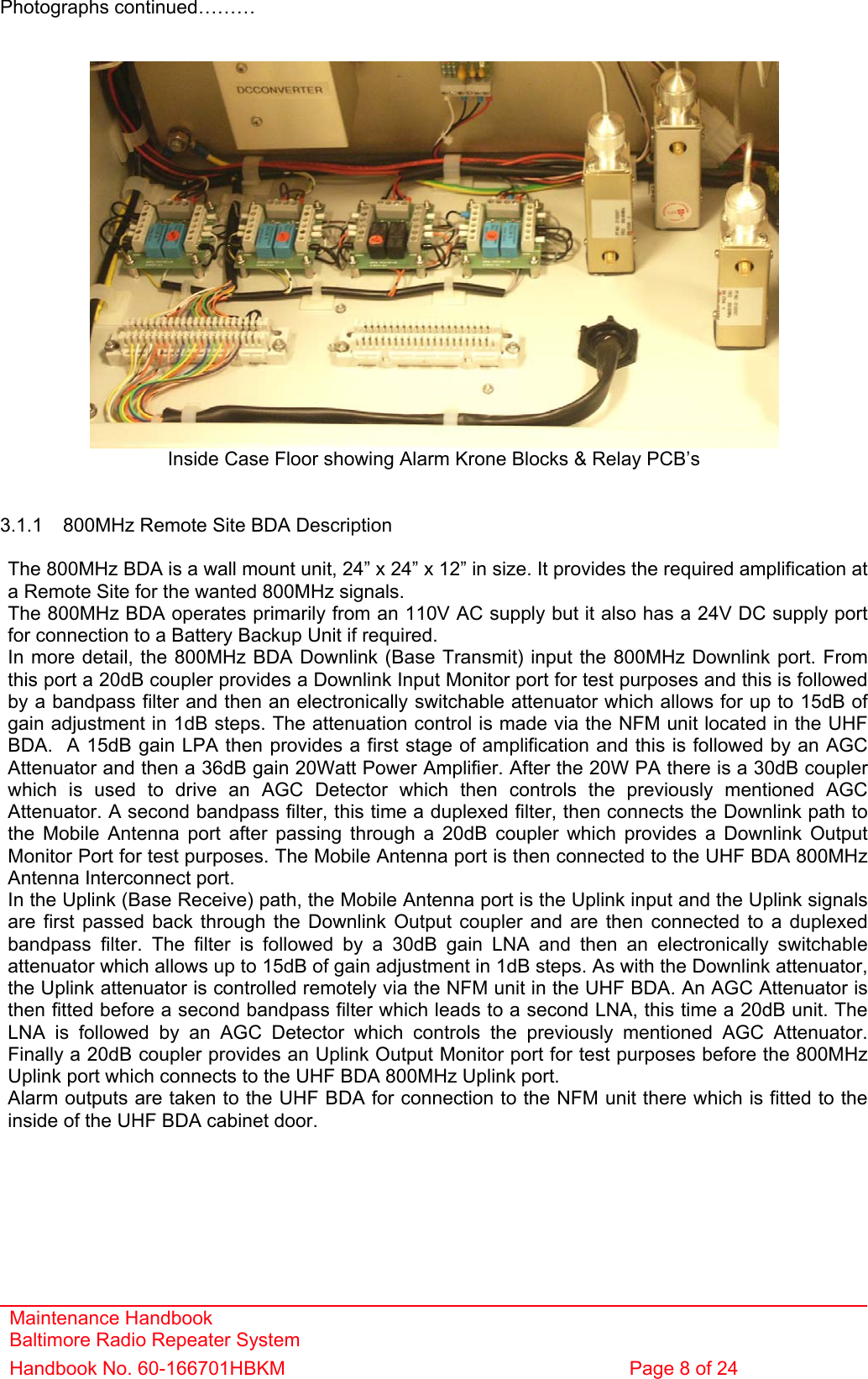
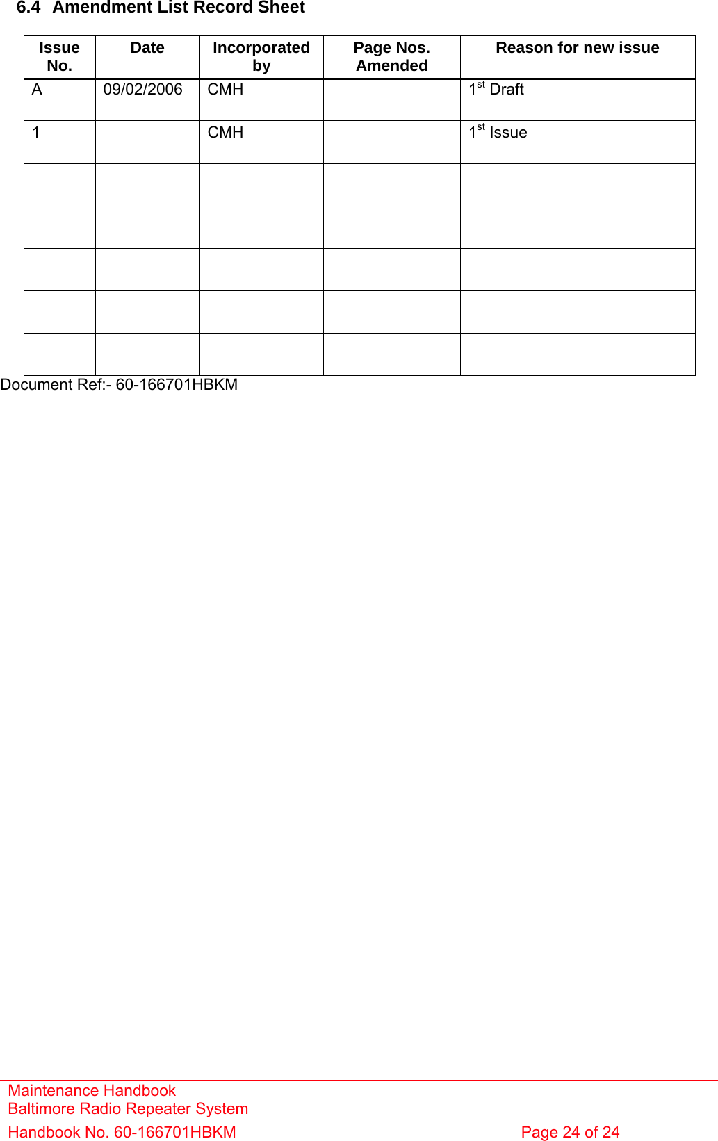
![Maintenance Handbook Baltimore Radio Repeater System Handbook No. 60-166701HBKM Page 14 of 24 3.1.8 800MHz 20/1W REMOTE SITE BDA (60-166701) Parts List 02-005801 8 POLE COMBLINE FILTER 4 07-002917 30dB COUPLER 1 07-002927 20dB COUPLER 2 10-001205 15dB REMOTE ATTENUATOR 2 11-005902 20dB GAIN LOW NOISE AMPLIFIER, 12V 1 11-006702 29dB GAIN LOW NOISE AMPLIFIER, 12V 1 12-021901 15dB GAIN 1WATT LOW POWER AMPLIFIER, 12V 1 12-023301 36dB GAIN 20WATT POWER AMPLIFIER, 24V 1 13-001710 VOLTAGE REGULATOR BOARD 5.0V 1 13-001803 DUAL DC/DC CONVERTER 24V-12V 1A 1 13-001822 DC-DC CONVERTER COVER 1 13-003301 MAINS FILTER 8AMP ASSEMBLY 1 17-000126 CELL ENHANCER LABEL 6 DIGIT 1 17-000526 10W HEATSINK THERMAL GASKET 1 17-001109 CE AGC UNIT LOG DETECTOR/AMP ASSY (12v) 2 17-001201 C/E AGC UNIT ATTENUATOR ASSY 2 17-001528 20W HEATSINK/BLANKING PLATE GASKET 1 17-002020 620 x 620 x 250mm IP65 WALL MOUNT ENCLOSURE 1 17-002021 BASE PLATE 585x570mm FOR 17-002020 1 17-013103 1" PROBE WITH RMS DETECTOR & 20dB COUPLER 1 20-001601 12V RELAY BOARD 3 20-001602 24V RELAY BOARD 1 80-031820 20W PA HEATSINK 1 80-310420 BCC 400W POWER SUPPLY HEATSINK 1 90-100010 MAINS LEAD '6 AMP' for USA 1 90-200004 DC INPUT LEAD, FREE SOCKET 1 91-030002 N ADAPTOR PANEL FEMALE:FEMALE 3 91-130001 SMA ADAPTOR 'T' ALL FEMALE 3 GHZ 1 91-500011 POWER 3POLE PANEL PLUG SEALED IP68 1 91-500013 POWER 2POLE PANEL PLUG SEALED IP68 1 91-500015 POWER CONNECTOR CAP SEALED with INT. THREAD 3 91-500043 POWER 25 POLE PANEL PLUG SEALED IP68 1 91-510035 3 WAY MATE N LOK PLUG HOUSING 1 91-510037 POWER 25 POLE FREE SOCKET SEALED IP68 1 91-520032 MATE N LOK SOCKET CONTACT 20/14 AWG 3 91-520033 25 POLE CONNECTOR SOCKET CONTACTS 25 91-520034 25 POLE CONNECTOR PIN CONTACTS 25 91-600014 'D' 9 WAY SOCKET 5 91-640004 LARGE PIN FOR 91-660001 D SOCKET 2 91-660001 2W5 MIXED D TYPE SOCKET (7 WAY) 1 91-700008 5 WAY 0.1' IDC CONNECTOR 1 91-800003 10 WAY KRONE MODULE 2 93-930003 SMA COAX TERMINATION [RADIAL] 1 96-110047 20A ATO FUSE 2 96-300054 24V 17A PSU 400W (XP BCC) 1 96-700034 LED RED 5mm IP67 1 96-700035 LED GREEN 5mm IP67 1 96-900018 AC TRIP SWITCH (5 AMP M.C.B.) 1 96-920037 THERMAL SWITCH 70c N/C 1A TO-220 1 97-000001 'SAREL' S/S HEAVY DUTY WALL BRACKET (4) 1 97-300010 SUPPLY INPUT COVER 2 97-300028 DC BOX 24V ATO TYPE 2 ASSEMBLY 1 97-400010 BLACK HANDLE 50mm HIGH 2 97-900004 RUBBER FOOT 4](https://usermanual.wiki/PBE-Europe-as-Axell-Wireless/60-1667SERIES/User-Guide-714792-Page-14.png)
![Maintenance Handbook Baltimore Radio Repeater System Handbook No. 60-166701HBKM Page 17 of 24 5. FAULT FINDING / MAINTENANCE 5.1 Tools & Test Equipment The minimum tools and test equipment needed to successfully service this AFL product are as follows:- Spectrum analyser: 100kHz to 2GHz (Dynamic range = 90dB). Signal Generator: 30MHz to 2GHz (-120dBm to 0dBm o/p level). Attenuator: 20dB, 10W, DC-2GHz, (N male – N female). Test Antenna: Yagi or dipole for operating frequency. Digital multi-meter: Universal Volt-Ohm-Amp meter. Test cable x 2: N male – N male, 2M long RG214. Test cable x 2: SMA male – N male, 1m long RG223. Hand tools: Philips #1&2 tip screwdriver. 3mm flat bladed screwdriver. SMA spanner and torque setter. 5.2 Basic Fault Finding In the event that the performance of the system is suspect, a methodical and logical approach to the problem will reveal the cause of the difficulty. The system consists of separate modules in a wall-mounted enclosure. Transmissions from the main base stations are passed though the system to the mobile radio equipment; this could be a handheld radio or a transceiver in a vehicle. This path is referred to as the downlink. The return signal path from mobile radio equipment to the base station is referred to as the uplink. The first fault finding operation is to check the alarms of each of the active units and determine that the power supplies to the equipment are connected and active. This can be achieved remotely (via CEMS, the RS232 Coverage Enhancement Management System, if fitted), or locally with the front panel LEDs. The green LED on the door should be illuminated, while the red alarm indicator should be off. If an alarm is on, then that individual module must be isolated and individually tested against the original test specification. The individual amplifier units have a green LED showing through a hole in their cover/lid, which is illuminated if the unit is working correctly. (Without active power supplies there can be no alarm LED indicators, however without DC power, the fail-safe summary alarm system [normally closed relay contacts] will be an open circuit, thereby activating any externally connected system.) If an amplifier is suspect, check the DC power supply to the unit. If no other fault is apparent use a spectrum analyser to measure the incoming signal level at the input and then after reconnecting the amplifier input, measure the output level. Consult with the system diagram to determine the expected gain and compare result. In the event that there are no alarms on and all units appear to be functioning it will be necessary to test the system in a systematic manner to confirm correct operation.](https://usermanual.wiki/PBE-Europe-as-Axell-Wireless/60-1667SERIES/User-Guide-714792-Page-17.png)
![Maintenance Handbook Baltimore Radio Repeater System Handbook No. 60-166701HBKM Page 23 of 24 6.3 EC Declaration of Conformity In accordance with BS EN ISO/IEC 17050-1&-2:2004 Aerial Facilities Limited Aerial House Asheridge Road Chesham Buckinghamshire HP5 2QD United Kingdom DECLARES, UNDER OUR SOLE RESPONSIBILITY THAT THE FOLLOWING PRODUCT: PRODUCT PART NO[S] 60-166701 PRODUCT DESCRIPTION Baltimore Transit radio repeaters IN ACCORDANCE WITH THE FOLLOWING DIRECTIVES: 1999/5/EC The Radio & Telecommunications Terminal Equipment Directive Annex V and its amending directives HAS BEEN DESIGNED AND MANUFACTURED TO THE FOLLOWING STANDARD[S] OR OTHER NORMATIVE DOCUMENT[S]: BS EN 60950 Information technology equipment. Safety. General requirements ETS EN 301 489-1 EMC standard for radio equipment and services. Part 1. Common technical requirements I hereby declare that the equipment named above has been designed to comply with the relevant sections of the above referenced specifications. The unit complies with all essential requirements of the Directives. SIGNED B S BARTON TECHNICAL DIRECTOR DATE: 16/02/2006 Registered Office: Aerial House, Asheridge Road, Chesham, Buckinghamshire, HP5 2QD England Registered No. 4042808 (England) www.aerialfacilities.com](https://usermanual.wiki/PBE-Europe-as-Axell-Wireless/60-1667SERIES/User-Guide-714792-Page-23.png)