PBE Europe as Axell Wireless 60-1667SERIES 800MHz Remote Repeater type 60-166701 User Manual
Axell Wireless 800MHz Remote Repeater type 60-166701
User manual

Handbook Number 60-166701HBKM Issue No. A Date 15/02/2006 Page 1 of 24
Baltimore Transit
Radio Repeater System
User/Maintenance Handbook (3)
for
Intelect Corp.
AFL Works Order: Q113737
AFL product part No.: 60-166701

Maintenance Handbook
Baltimore Radio Repeater System
Handbook No. 60-166701HBKM Page 2 of 24
1. INTRODUCTION
Scope and Purpose of this Document
This handbook is for use solely with the equipment identified by the AFL Part Number shown on the
front cover. It is not to be used with any other equipment unless specifically authorised by Aerial
Facilities Limited. This is a controlled release document and, as such, becomes a part of Aerial
Facilities’ Total Quality Management System. Alterations and modification may therefore only be
performed by Aerial Facilities Ltd.
AFL recommends that the installer of this equipment familiarise his/herself with the safety and
installation procedures contained within this document before installation commences.
The purpose of this handbook is to provide the user/maintainer with sufficient information to service
and repair the equipment to the level agreed. Maintenance and adjustments to any deeper level must
be performed by AFL, normally at the company’s repair facility in Chesham, England.
This handbook has been prepared in accordance with BS 4884, and AFL’s Quality procedures, which
maintain the company’s registration to BS EN ISO 9001:2000 and to the R&TTE Directive of the
European Parliament. Copies of the relevant certificates and the company Quality Manual can be
supplied on application to the Quality Manager.
This document fulfils the relevant requirements of Article 6 of the R&TTE Directive.
Limitation of Liability Notice
This manual is written for the use of technically competent operators/service persons. No liability is
accepted by AFL for use or misuse of this manual, the information contained therein, or the
consequences of any actions resulting from the use of the said information, including, but not limited
to, descriptive, procedural, typographical, arithmetical, or listing errors.
Furthermore, AFL does not warrant the absolute accuracy of the information contained within this
manual, or its completeness, fitness for purpose, or scope.
AFL has a policy of continuous product development and enhancement, and as such, reserves the
right to amend, alter, update and generally change the contents, appearance and pertinence of this
document without notice.
All AFL products carry a twelve month warranty from date of shipment. The warranty is expressly on a
return to base repair or exchange basis and the warranty cover does not extend to on-site repair or
complete unit exchange.

Maintenance Handbook
Baltimore Radio Repeater System
Handbook No. 60-166701HBKM Page 3 of 24
Table of Contents
1. INTRODUCTION.......................................................................................................................... 2
Scope and Purpose of this Document................................................................................................. 2
Limitation of Liability Notice................................................................................................................. 2
2. SAFETY CONSIDERATIONS ...................................................................................................... 4
2.1 Earthing of Equipment .............................................................................................................. 4
2.2 Electric Shock Hazard............................................................................................................... 4
2.3 RF Radiation Hazard ................................................................................................................ 4
2.4 Chemical Hazard ...................................................................................................................... 5
2.5 Laser safety .............................................................................................................................. 5
2.6 Emergency Contact Numbers................................................................................................... 5
3. EQUIPMENT OVERVIEW/SPECIFICATIONS............................................................................. 6
3.1 800MHz 20W/1W Bi-Directional Amplifier (60-166701)............................................................ 7
3.1.P 800MHz 20W/1W Bi-Directional Amplifier Photographs .................................................... 7
3.1.1 800MHz Remote Site BDA Description.............................................................................. 8
3.1.2 800MHz Remote Site BDA Technical Specifications ......................................................... 9
3.1.4 800MHz Remote Site BDA Alarm Wiring, Drg. Nō. 60-166751........................................ 10
3.1.5 800MHz Remote Site BDA O/P Connections for NFM, Drg. Nō. 60-166752 ................... 11
3.1.6 800MHz Remote Site BDA System Diagram, Drg. Nō. 60-166781.................................. 12
3.1.7 800MHz Remote Site BDA Outline Drawing, Drg. Nō. 60-166791................................... 13
3.1.8 800MHz 20/1W REMOTE SITE BDA (60-166701) Parts List .......................................... 14
4. INSTALLATION & COMMISIONING.......................................................................................... 15
4.1 Initial Installation Record......................................................................................................... 15
4.2 Optical Connections................................................................................................................ 15
4.3 Wall Mounted Equipment........................................................................................................ 16
4.4 RF Connections ...................................................................................................................... 16
4.5 RF Commissioning.................................................................................................................. 16
5. FAULT FINDING / MAINTENANCE ........................................................................................... 17
5.1 Tools & Test Equipment..........................................................................................................17
5.2 Basic Fault Finding ................................................................................................................. 17
5.3 Quick Fault Checklist .............................................................................................................. 18
5.4 Downlink ................................................................................................................................. 18
5.5 Uplink...................................................................................................................................... 18
5.6 Fault repair.............................................................................................................................. 18
5.7 Service Support ...................................................................................................................... 18
5.8 Care of Modules...................................................................................................................... 19
5.9 Module Removal (LNAs, general procedure):......................................................................... 19
5.10 Module Replacement (general): .......................................................................................... 19
5.11 Power Amplifiers.................................................................................................................. 19
5.12 Low Power Amplifier Replacement...................................................................................... 20
5.13 Module Transportation:........................................................................................................ 20
6 APPENDIXES ............................................................................................................................ 21
6.1 Glossary of Terms used in this document............................................................................... 21
6.2 AFL RF Module Drawing Key ................................................................................................. 22
6.3 EC Declaration of Conformity ................................................................................................. 23
6.4 Amendment List Record Sheet ............................................................................................... 24
Maintenance Handbook
Baltimore Radio Repeater System
Handbook No. 60-166701HBKM Page 4 of 24
2. SAFETY CONSIDERATIONS
2.1 Earthing of Equipment
Equipment supplied from the mains must be connected to grounded outlets and earthed
in conformity with appropriate local, national and international electricity supply and
safety regulations.
2.2 Electric Shock Hazard
The risk of electrical shocks due to faulty mains driven power supplies whilst
potentially ever present in any electrical equipment, would be minimised by adherence
to good installation practice and thorough testing at the following stages:
a) Original assembly.
b) Commissioning.
c) Regular intervals, thereafter.
All test equipment must be in good working order prior to its use. High current power supplies can be
dangerous because of the possibility of substantial arcing. Always switch off during disconnection and
reconnection.
2.3 RF Radiation Hazard
RF radiation, (especially at UHF frequencies) arising from transmitter outputs
connected to AFL’s equipment, must be considered a safety hazard.
This condition might only occur in the event of cable disconnection, or because a
‘spare’ output has been left unterminated. Either of these conditions would impair the
system’s efficiency. No investigation should be carried out until all RF power sources have been
removed. This would always be a wise precaution, despite the severe mismatch between the
impedance of an N type connector at 50Ω, and that of free space at 377Ω, which would severely
mitigate against the efficient radiation of RF power. Radio frequency burns could also be a hazard, if
any RF power carrying components were to be carelessly touched!
Antenna positions should be chosen to comply with requirements (both local & statutory) regarding
exposure of personnel to RF radiation. When connected to an antenna, the unit is capable of
producing RF field strengths, which may exceed guideline safe values especially if used with
antennas having appreciable gain. In this regard the use of directional antennas with backscreens
and a strict site rule that personnel must remain behind the screen while the RF power is on, is
strongly recommended.
Where the equipment is used near power lines, or in association with temporary masts not having
lightning protection, the use of a safety earth connected to the case-earthing bolt is strongly advised.
Maintenance Handbook
Baltimore Radio Repeater System
Handbook No. 60-166701HBKM Page 5 of 24
2.4 Chemical Hazard
Beryllium Oxide, also known as Beryllium Monoxide, or Thermalox™, is sometimes
used in devices within equipment produced by Aerial Facilities Ltd. Beryllium oxide
dust can be toxic if inhaled, leading to chronic respiratory problems. It is harmless if
ingested or by contact.
Products that contain beryllium are load terminations (dummy loads) and some power amplifiers.
These products can be identified by a yellow and black “skull and crossbones” danger symbol (shown
above). They are marked as hazardous in line with international regulations, but pose no threat under
normal circumstances. Only if a component containing beryllium oxide has suffered catastrophic
failure, or exploded, will there be any danger of the formation of dust. Any dust that has been created
will be contained within the equipment module as long as the module remains sealed. For this reason,
any module carrying the yellow and black danger sign should not be opened. If the equipment is
suspected of failure, or is at the end of its life-cycle, it must be returned to Aerial Facilities Ltd for
disposal.
To return such equipment, please contact the Quality Department, who will give you a Returned
Materials Authorisation (RMA) number. Please quote this number on the packing documents, and on
all correspondence relating to the shipment.
PolyTetraFluoroEthylene, (P.T.F.E.) and P.T.F.E. Composite Materials
Many modules/components in AFL equipment contain P.T.F.E. as part of the RF insulation barrier.
This material should never be heated to the point where smoke or fumes are evolved. Any person
feeling drowsy after coming into contact with P.T.F.E. especially dust or fumes should seek medical
attention.
2.5 Laser safety
General good working practices adapted from
EN60825-2: 2004/ EC 60825-2:2004
Do not stare with unprotected eyes or with any unapproved optical device at the fibre
ends or connector faces or point them at other people, Use only approved filtered or
attenuating viewing aids.
Any single or multiple fibre end or ends found not to be terminated (for example, matched, spliced)
shall be individually or collectively covered when not being worked on. They shall not be readily
visible and sharp ends shall not be exposed.
When using test cords, the optical power source shall be the last connected and the first
disconnected.
Use only approved methods for cleaning and preparing optical fibres and optical connectors, do not
allow any dirt/foreign material ingress on the optical connector bulkheads and always keep optical
connectors covered to avoid physical damage.
The optical fibre jumper cable maximum bend radius is 3 cm (1 ¼" ), any smaller radii may result in
optical cable breakage or excessive transmission losses.
Caution: Do not get the Fibre Optic units wet, they are NOT weather proof.
2.6 Emergency Contact Numbers
The AFL Quality Department can be contacted on:
Telephone +44 (0)1494 777000
Fax. +44 (0)1494 777002
e-mail mail to:qa@aerial.co.uk

Maintenance Handbook
Baltimore Radio Repeater System
Handbook No. 60-166701HBKM Page 6 of 24
3. EQUIPMENT OVERVIEW/SPECIFICATIONS
The Baltimore repeater system consists of several items of hardware:-
Master Site Preston UHF Air Interface Channelised Amplifier (60-166101, rack mounting)
Master Site OCC UHF Air Interface Channelised Amplifier (60-166201, rack mounting)
Preston Six-Way Fibre Optic Master Site (60-166301, rack mounting)
OCC Six-Way Fibre Optic Master Site (60-166401, rack mounting)
Remote Site High Power UHF Bi-Directional Amplifier (60-166501, wall mounting)
Remote Site 800MHz Bi-Directional Amplifier (60-166701, Wall Mounting)
MOCE Site Air Interface Repeater (60-166801, wall mounting)
6 x 114Ah Battery Backups (80-333201, wall mounting)
There are two master sites, one at PRESTON and one at OCC, each has a 19” rack cabinet
containing the four off-air receiving shelves, which also contain the power supplies and the DC/DC
converters (12V) for the FO shelf.
The master site equipment receives off-air transmissions which it channelises, (up to 16 channels)
and sends this downlink signal data to six fibre optic RX modules. Remotely sited cell enhancers
receive this FO data, demodulate and amplify it and feed it to local antennas or radiating cables.
At the remote sites, the same leaky feeder antennas receive mobile signals, band selectively amplify
them and send this uplink data back by FO to the master site where it is demodulated, channelised
and broadcast on the same air interface antenna that received the downlink signal.
20dB couplers fitted at various points in the system ‘tap-off’ a signal suitable for monitoring the RF
power in any path.
Each active device is alarm monitored and these alarms are available either as separate volt-free
relay contact pairs, in groups (e.g. all downlink power amplifiers), or as an alarm summary of the
whole system with locally visible indications (LED’s).
Six 114Ah battery backup systems ensure no loss of coverage should mains power fail. At the time of
writing this document no information was available on which items of the system were to be fitted to
the battery backups.
Maintenance Handbook
Baltimore Radio Repeater System
Handbook No. 60-166701HBKM Page 7 of 24
3.1 800MHz 20W/1W Bi-Directional Amplifier (60-166701)
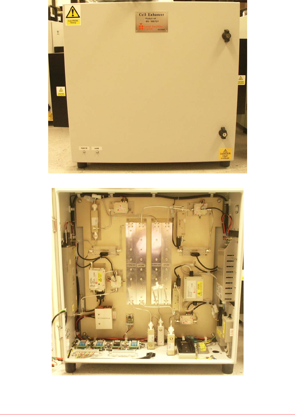
3.1.P 800MHz 20W/1W Bi-Directional Amplifier Photographs
Front View – Door Closed
Front View – Door Open
Maintenance Handbook
Baltimore Radio Repeater System
Handbook No. 60-166701HBKM Page 8 of 24
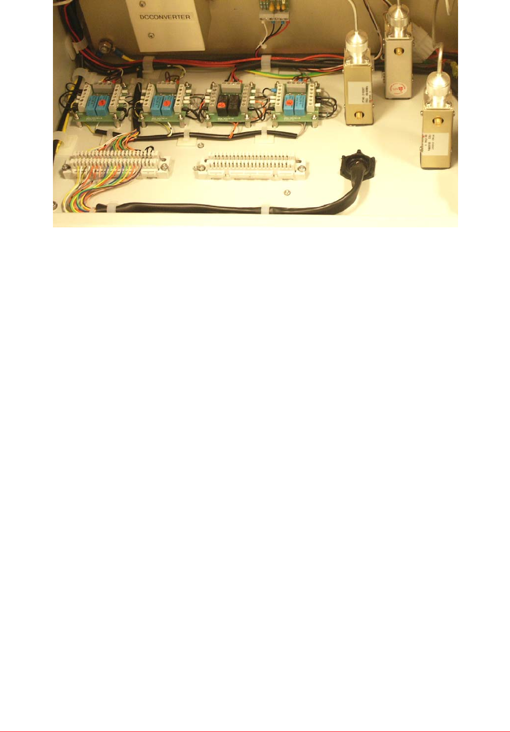
Photographs continued………
Inside Case Floor showing Alarm Krone Blocks & Relay PCB’s
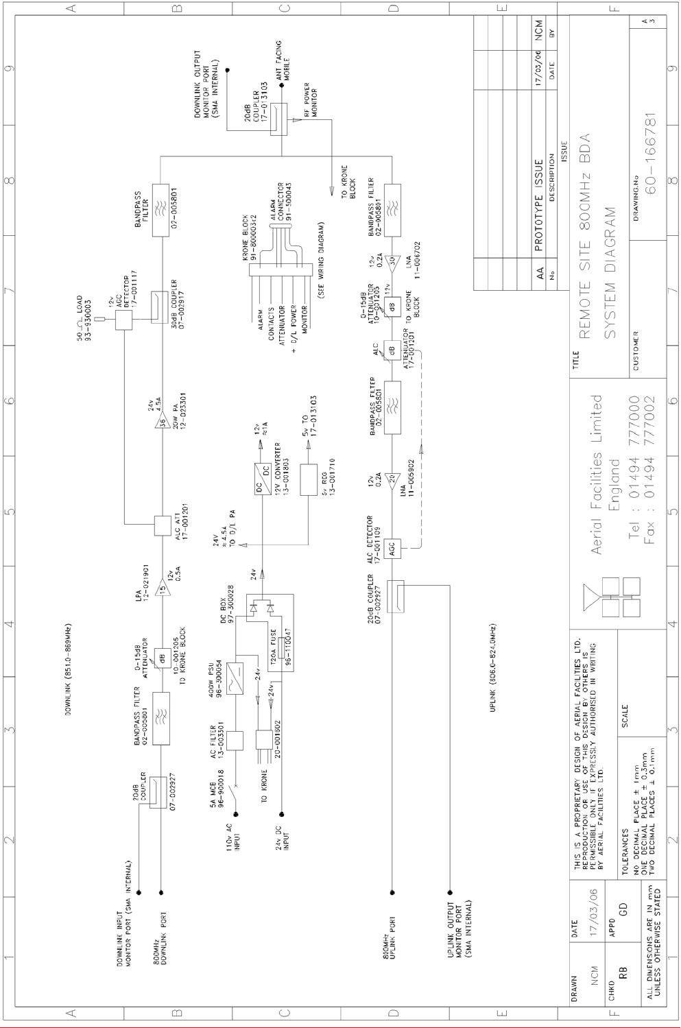
3.1.1 800MHz Remote Site BDA Description
The 800MHz BDA is a wall mount unit, 24” x 24” x 12” in size. It provides the required amplification at
a Remote Site for the wanted 800MHz signals.
The 800MHz BDA operates primarily from an 110V AC supply but it also has a 24V DC supply port
for connection to a Battery Backup Unit if required.
In more detail, the 800MHz BDA Downlink (Base Transmit) input the 800MHz Downlink port. From
this port a 20dB coupler provides a Downlink Input Monitor port for test purposes and this is followed
by a bandpass filter and then an electronically switchable attenuator which allows for up to 15dB of
gain adjustment in 1dB steps. The attenuation control is made via the NFM unit located in the UHF
BDA. A 15dB gain LPA then provides a first stage of amplification and this is followed by an AGC
Attenuator and then a 36dB gain 20Watt Power Amplifier. After the 20W PA there is a 30dB coupler
which is used to drive an AGC Detector which then controls the previously mentioned AGC
Attenuator. A second bandpass filter, this time a duplexed filter, then connects the Downlink path to
the Mobile Antenna port after passing through a 20dB coupler which provides a Downlink Output
Monitor Port for test purposes. The Mobile Antenna port is then connected to the UHF BDA 800MHz
Antenna Interconnect port.
In the Uplink (Base Receive) path, the Mobile Antenna port is the Uplink input and the Uplink signals
are first passed back through the Downlink Output coupler and are then connected to a duplexed
bandpass filter. The filter is followed by a 30dB gain LNA and then an electronically switchable
attenuator which allows up to 15dB of gain adjustment in 1dB steps. As with the Downlink attenuator,
the Uplink attenuator is controlled remotely via the NFM unit in the UHF BDA. An AGC Attenuator is
then fitted before a second bandpass filter which leads to a second LNA, this time a 20dB unit. The
LNA is followed by an AGC Detector which controls the previously mentioned AGC Attenuator.
Finally a 20dB coupler provides an Uplink Output Monitor port for test purposes before the 800MHz
Uplink port which connects to the UHF BDA 800MHz Uplink port.
Alarm outputs are taken to the UHF BDA for connection to the NFM unit there which is fitted to the
inside of the UHF BDA cabinet door.
Maintenance Handbook
Baltimore Radio Repeater System
Handbook No. 60-166701HBKM Page 9 of 24
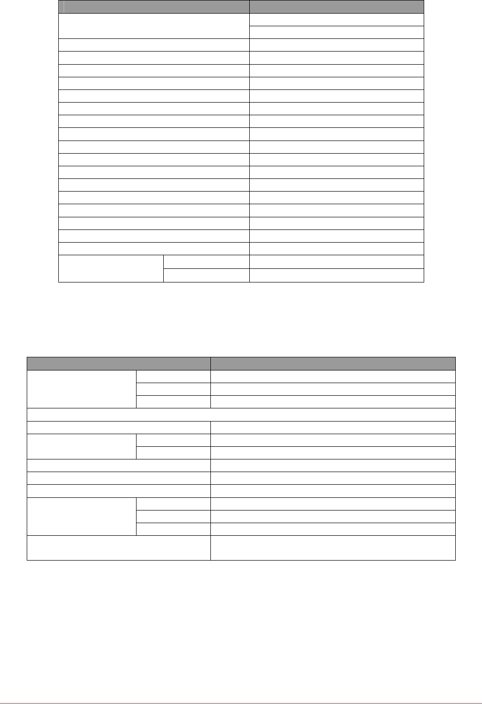
3.1.2 800MHz Remote Site BDA Technical Specifications
PARAMETER SPECIFICATION
851.0-869.0MHz (Downlink)
Frequency range: 806.0-824.0MHz (Uplink)
Bandwidth: 18MHz
Maximum Gain: 45dB
Passband Ripple: < +/-1.5dB
Remote Gain adjustment: 0-15dB (in 1dB steps)
Downlink 1dB Compression Point: +41.0dBm
Downlink 3rd Order Intercept Point: +61.0dBm
Uplink 1dB Compression Point: +18.0dBm
Uplink AGC setting: +0dBm
AGC dynamic range: > 30dB
Uplink 3rd Order Intercept Point: +31.0dBm
Monitor Ports: 3 (DL In, DL Out, UL Out)
Monitor Port Level: 20dBc
Noise Figure: <6.0dB at 40dB gain
Impedance: 50 ohms
RF Connectors: N type, female
Power Supply: 110V AC and/or 24V DC
Power consumption: <2A at 110V AC, <5.5A at 24V DC
operational: -25°C to +63°C
Temperature range: storage: -30°C to +70°C
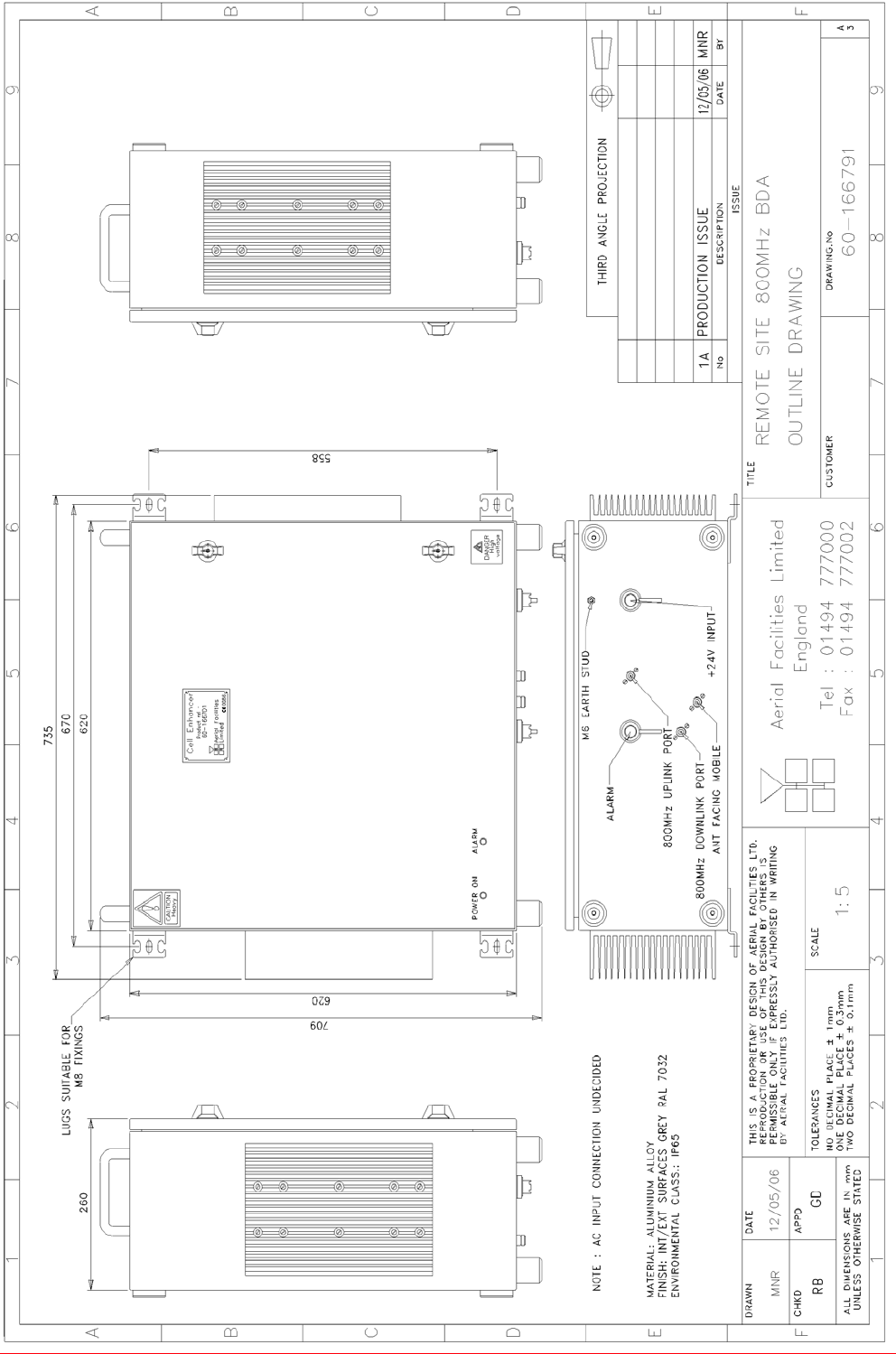
3.1.3 800MHz Remote Site BDA Mechanical Specifications
PARAMETER SPECIFICATION
Height: 620mm
Width: 620mm
Case size
Depth: 250mm
(excluding heatsinks, connectors, handles and feet)
Fixings: 4 holes on 670(w) x 558(h)mm
Operational: -25°C to +63°C Temperature Range:
Storage: -30°C to +70°C
Weight: >50kg
RF Connectors: N type female
Environmental Protection: IP65 (with door closed and all ports terminated)
Case: To RAL 7035
Heatsinks: Matt black (where fitted)
Finish:
Handles: Black technopolymer
Supply Cable: Unit supplied with suitable supply input leads with
connector and appropriate length of cable
Maintenance Handbook
Baltimore Radio Repeater System
Handbook No. 60-166701HBKM Page 10 of 24
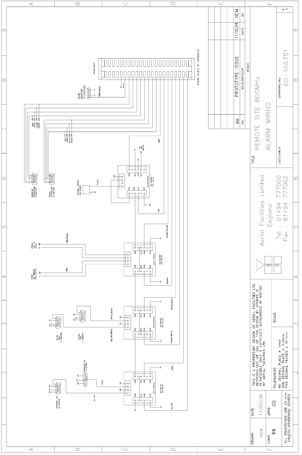
3.1.4 800MHz Remote Site BDA Alarm Wiring, Drg. Nō. 60-166751
Maintenance Handbook
Baltimore Radio Repeater System
Handbook No. 60-166701HBKM Page 11 of 24
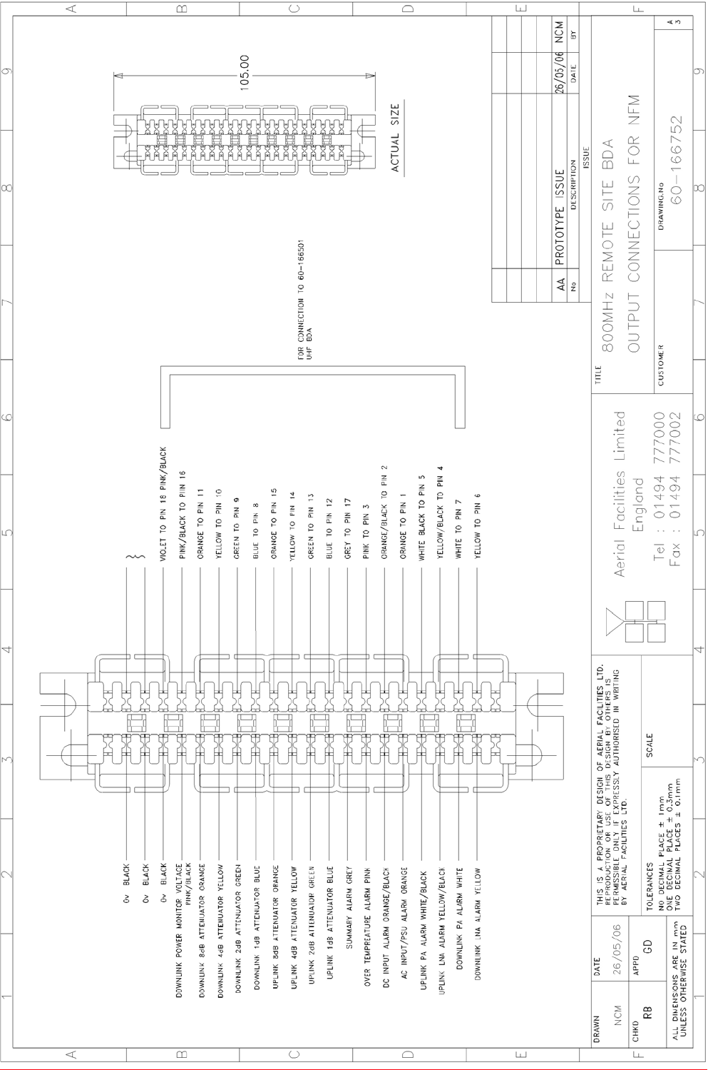
3.1.5 800MHz Remote Site BDA O/P Connections for NFM, Drg. Nō. 60-166752
Maintenance Handbook
Baltimore Radio Repeater System
Handbook No. 60-166701HBKM Page 12 of 24
3.1.6 800MHz Remote Site BDA System Diagram, Drg. Nō. 60-166781
Maintenance Handbook
Baltimore Radio Repeater System
Handbook No. 60-166701HBKM Page 13 of 24
3.1.7 800MHz Remote Site BDA Outline Drawing, Drg. Nō. 60-166791

Maintenance Handbook
Baltimore Radio Repeater System
Handbook No. 60-166701HBKM Page 14 of 24
3.1.8 800MHz 20/1W REMOTE SITE BDA (60-166701) Parts List
02-005801 8 POLE COMBLINE FILTER 4
07-002917 30dB COUPLER 1
07-002927 20dB COUPLER 2
10-001205 15dB REMOTE ATTENUATOR 2
11-005902 20dB GAIN LOW NOISE AMPLIFIER, 12V 1
11-006702 29dB GAIN LOW NOISE AMPLIFIER, 12V 1
12-021901 15dB GAIN 1WATT LOW POWER AMPLIFIER, 12V 1
12-023301 36dB GAIN 20WATT POWER AMPLIFIER, 24V 1
13-001710 VOLTAGE REGULATOR BOARD 5.0V 1
13-001803 DUAL DC/DC CONVERTER 24V-12V 1A 1
13-001822 DC-DC CONVERTER COVER 1
13-003301 MAINS FILTER 8AMP ASSEMBLY 1
17-000126 CELL ENHANCER LABEL 6 DIGIT 1
17-000526 10W HEATSINK THERMAL GASKET 1
17-001109 CE AGC UNIT LOG DETECTOR/AMP ASSY (12v) 2
17-001201 C/E AGC UNIT ATTENUATOR ASSY 2
17-001528 20W HEATSINK/BLANKING PLATE GASKET 1
17-002020 620 x 620 x 250mm IP65 WALL MOUNT ENCLOSURE 1
17-002021 BASE PLATE 585x570mm FOR 17-002020 1
17-013103 1" PROBE WITH RMS DETECTOR & 20dB COUPLER 1
20-001601 12V RELAY BOARD 3
20-001602 24V RELAY BOARD 1
80-031820 20W PA HEATSINK 1
80-310420 BCC 400W POWER SUPPLY HEATSINK 1
90-100010 MAINS LEAD '6 AMP' for USA 1
90-200004 DC INPUT LEAD, FREE SOCKET 1
91-030002 N ADAPTOR PANEL FEMALE:FEMALE 3
91-130001 SMA ADAPTOR 'T' ALL FEMALE 3 GHZ 1
91-500011 POWER 3POLE PANEL PLUG SEALED IP68 1
91-500013 POWER 2POLE PANEL PLUG SEALED IP68 1
91-500015 POWER CONNECTOR CAP SEALED with INT. THREAD 3
91-500043 POWER 25 POLE PANEL PLUG SEALED IP68 1
91-510035 3 WAY MATE N LOK PLUG HOUSING 1
91-510037 POWER 25 POLE FREE SOCKET SEALED IP68 1
91-520032 MATE N LOK SOCKET CONTACT 20/14 AWG 3
91-520033 25 POLE CONNECTOR SOCKET CONTACTS 25
91-520034 25 POLE CONNECTOR PIN CONTACTS 25
91-600014 'D' 9 WAY SOCKET 5
91-640004 LARGE PIN FOR 91-660001 D SOCKET 2
91-660001 2W5 MIXED D TYPE SOCKET (7 WAY) 1
91-700008 5 WAY 0.1' IDC CONNECTOR 1
91-800003 10 WAY KRONE MODULE 2
93-930003 SMA COAX TERMINATION [RADIAL] 1
96-110047 20A ATO FUSE 2
96-300054 24V 17A PSU 400W (XP BCC) 1
96-700034 LED RED 5mm IP67 1
96-700035 LED GREEN 5mm IP67 1
96-900018 AC TRIP SWITCH (5 AMP M.C.B.) 1
96-920037 THERMAL SWITCH 70c N/C 1A TO-220 1
97-000001 'SAREL' S/S HEAVY DUTY WALL BRACKET (4) 1
97-300010 SUPPLY INPUT COVER 2
97-300028 DC BOX 24V ATO TYPE 2 ASSEMBLY 1
97-400010 BLACK HANDLE 50mm HIGH 2
97-900004 RUBBER FOOT 4

Maintenance Handbook
Baltimore Radio Repeater System
Handbook No. 60-166701HBKM Page 15 of 24
4. INSTALLATION & COMMISIONING
4.1 Initial Installation Record
When this equipment is initially commissioned, please use the equipment set-up record sheet in the
Appendices. This will help both the installation personnel and AFL should these figures be needed for
future reference or diagnosis.
4.2 Optical Connections
The optical input and output ports will be located on the appropriate E/O shelf as shown in the rack
layout drawing and the system layout drawing. The ports are supplied with a green plastic cover,
which must be removed prior to the connection of the fibre cable. Ensure that transmitter and receiver
fibre cable are identified to prevent misconnection. At the master site, the fibre transmitters are in the
downlink path with the receivers in the uplink. At remote sites the fibre transmitters are in the uplink
with the receivers in the downlink. Observe optical safety precautions in section 1. when handling
fibre optic components.
The individual fibre optic units are fitted with a pair of status indicators on their front panels. One is a
green LED, which indicates that the unit is connected to a 12 Volt DC power supply. This indicator is
common to both transmit and receive units. The second LED on the RX module indicates that the
laser is operating (transmitting). On the RX unit the second LED indicates that a laser-light signal is
being received.
When all the fibre connections are completed and power to each site is connected each fibre unit
must show two illuminated indicators.
Ensure that connections are kept clean and are fully tightened.

Maintenance Handbook
Baltimore Radio Repeater System
Handbook No. 60-166701HBKM Page 16 of 24
4.3 Wall Mounted Equipment
The procedure for installing and commissioning a wall-mounted Bi-Directional Amplifier unit is
generally as follows:
Fix the unit in the chosen position. Ensure the mounting site is a straight, smooth, perpendicular
surface (brick or concrete recommended). Mounting bracket centres/dimensions will be found in the
specifications section (3.3). After fixing, mechanically test the installation before proceeding.
ix the two antennas (antenna isolation should already have been performed see section 4.2) and
connect them to the BDA.
Connect a suitable mains and/or battery power supply to the unit.
Connect the alarm interface connectors.
Calculate the attenuation settings required for the uplink and the downlink paths, and set the
attenuators as described elsewhere in this document.
Double-check all RF and power connections before switching the BDA mains on with the small switch
located inside the unit on the lower right hand side of the case.
Alarms may not settle for several seconds after switch-on, but they should extinguish after a short
time (up to 15 seconds).
Make test calls via the equipment to ensure correct operation, if possible monitoring the signal levels
during these calls to ensure that the uplink and downlink RF levels are as anticipated.
4.4 RF Connections
Care must be taken to ensure that the correct connections are made with particular attention made to
the optical TX/RX ports.
Ensure that connections are kept clean and are fully tightened.
4.5 RF Commissioning
Once all connections are made the equipment is ready for commissioning.
To commission the system the test equipment detailed in Section 5.1 will be required.
Using the system diagrams and the end-to-end test specification, the equipment should be tested to
ensure correct operation.
On initial power up the system alarm indicators on the front panels of the equipment should be
checked. A red LED illuminated indicates a fault in that particular shelf that must be investigated
before proceeding with the commissioning. A green LED on each shelf illuminates, to indicate that the
power supply is connected to the shelf.
In the event that any part of the system does not function correctly as expected, check all connections
to ensure that they are to the correct port, that the interconnecting cables are not faulty and that they
are tightened. The majority of commissioning difficulties arise from problems with interconnecting
cables and connectors.

Maintenance Handbook
Baltimore Radio Repeater System
Handbook No. 60-166701HBKM Page 17 of 24
5. FAULT FINDING / MAINTENANCE
5.1 Tools & Test Equipment
The minimum tools and test equipment needed to successfully service this AFL product are as
follows:-
Spectrum analyser: 100kHz to 2GHz (Dynamic range = 90dB).
Signal Generator: 30MHz to 2GHz (-120dBm to 0dBm o/p level).
Attenuator: 20dB, 10W, DC-2GHz, (N male – N female).
Test Antenna: Yagi or dipole for operating frequency.
Digital multi-meter: Universal Volt-Ohm-Amp meter.
Test cable x 2: N male – N male, 2M long RG214.
Test cable x 2: SMA male – N male, 1m long RG223.
Hand tools:
Philips #1&2 tip screwdriver.
3mm flat bladed screwdriver.
SMA spanner and torque setter.
5.2 Basic Fault Finding
In the event that the performance of the system is suspect, a methodical and logical approach to the
problem will reveal the cause of the difficulty. The system consists of separate modules in a wall-
mounted enclosure.
Transmissions from the main base stations are passed though the system to the mobile radio
equipment; this could be a handheld radio or a transceiver in a vehicle. This path is referred to as the
downlink. The return signal path from mobile radio equipment to the base station is referred to as the
uplink.
The first fault finding operation is to check the alarms of each of the active units and determine that
the power supplies to the equipment are connected and active.
This can be achieved remotely (via CEMS, the RS232 Coverage Enhancement Management System,
if fitted), or locally with the front panel LEDs. The green LED on the door should be illuminated, while
the red alarm indicator should be off. If an alarm is on, then that individual module must be isolated
and individually tested against the original test specification. The individual amplifier units have a
green LED showing through a hole in their cover/lid, which is illuminated if the unit is working
correctly. (Without active power supplies there can be no alarm LED indicators, however without DC
power, the fail-safe summary alarm system [normally closed relay contacts] will be an open circuit,
thereby activating any externally connected system.)
If an amplifier is suspect, check the DC power supply to the unit. If no other fault is apparent use a
spectrum analyser to measure the incoming signal level at the input and then after reconnecting the
amplifier input, measure the output level. Consult with the system diagram to determine the expected
gain and compare result.
In the event that there are no alarms on and all units appear to be functioning it will be necessary to
test the system in a systematic manner to confirm correct operation.

Maintenance Handbook
Baltimore Radio Repeater System
Handbook No. 60-166701HBKM Page 18 of 24
5.3 Quick Fault Checklist
All AFL equipment is individually tested to specification prior to despatch. Failure of this type of
equipment is not common. Experience has shown that a large number of fault conditions relating to
installations result from simple causes often occurring as result of transportation, unpacking and
installation. Below are listed some common problems which have resulted in poor performance or an
indicated non-functioning of the equipment.
Mains power not connected or not switched on.
External connectors not fitted or incorrectly fitted.
Internal connectors/ports becoming loose due to transport vibration.
Wiring becoming detached as a result of heavy handling.
Input signals not present due to faults in the aerial and feeder system.
Base transmissions not present due to faults at the base station.
Modems fitted with incorrect software configuration/and or PIN No.’s.
Changes to channel frequencies and inhibiting channels.
Hand held radio equipment not correctly set to repeater channels.
Hand held radio equipment not correctly set to base station.
5.4 Downlink
Confirm that there is a signal at the expected frequency and strength from the base station(s). If this is
not present then the fault may lay outside the system. To confirm this, inject a downlink frequency
signal from a known source at the master site BTS input and check for output at the remote site
feeder output.
If a signal is not received at the output it will be necessary to follow the downlink path through the
system to find a point at which the signal is lost.
5.5 Uplink
Testing etc. of the uplink paths is similar to the downlink paths, except for the frequencies involved.
5.6 Fault repair
Once a faulty component has been identified, a decision must be made on the appropriate course to
carry out a repair. A competent engineer can quickly remedy typical faults such as faulty connections
or cables. The exceptions to this are cable assemblies connecting bandpass filter assemblies
(duplexers) that are manufactured to critical lengths to maintain a 50-ohm system. Care should be
taken when replacing cables or connectors to ensure that items are of the correct specification. The
repair of component modules such as amplifiers and bandpass filters will not usually be possible in
the field, as they frequently require specialist knowledge and test equipment to ensure correct
operation. It is recommended that items of this type are replaced with a spare unit and the faulty unit
returned to AFL for repair.
Following the repair of any part of the system it is recommended that a full end-to-end test is carried
out in accordance with the test specification and that the coverage is checked by survey.
It is important to bear in mind that the system includes antennas and base stations that may be faulty
or may have been damaged.
5.7 Service Support
Advice and assistance with maintaining and servicing this system are available by contacting Aerial
Facilities Ltd.

Maintenance Handbook
Baltimore Radio Repeater System
Handbook No. 60-166701HBKM Page 19 of 24
5.8 Care of Modules
Many of the active modules contain semiconductor devices utilising MOS technology, which can be
damaged by electrostatic discharge. Correct handling of such modules is mandatory to ensure their
long-term reliability. Good engineering practices should be observed at all times.
To prevent damage to a module, it must be withdrawn/inserted with care.
5.9 Module Removal (LNAs, general procedure):
The following general rules should be followed to remove a module:
1) Remove power to the unit
2) Remove all connectors (RF, DC/alarm)
3) Release module retaining screws.
4) Slowly but firmly, pull the module straight out of its position. Take care not to twist/turn the
module during withdrawal.
5.10 Module Replacement (general):
1) Carefully align the module into its location then slowly push the module directly straight into its
position, taking care not to twist/turn it during insertion.
2) Reconnect all connectors, RF, alarm, power etc.
3) Replace retaining screws (if any).
4) Double-check all connections before applying power.
5.11 Power Amplifiers
1) Remove power to the unit. (Switch off at mains/battery)
2) Disconnect multi-way alarm ‘D’ type connector
3) Carefully disconnect the RF input and output coaxial connectors (usually SMA)
4) If the amplifier to be removed has a heatsink attached, there may be several different ways it
can have been assembled. The most commonly used method, is screws through the front of the
heatsink to threaded screw holes (or nuts and bolts), into the amplifier within the main case. If the
heatsink is mounted on the rear of the main case (e.g., against a wall in the case of wall mounted
enclosures), then the fixing method for the heatsink will be from within the case, (otherwise the
enclosure would have to be removed from the wall in order to remove the heatsink).
When the heatsink has been removed, the amplifier may be unscrewed from the main casing by its
four corner fixings and gently withdrawn.
Fitting a new power amplifier module will be the exact reverse of the above.
Note: Do not forget to apply fresh heatsink compound to the heatsink/main case joint and also
between the amplifier and the main case.

Maintenance Handbook
Baltimore Radio Repeater System
Handbook No. 60-166701HBKM Page 20 of 24
5.12 Low Power Amplifier Replacement
Disconnect the mains power supply and disconnect the 24V dc supply connector for the LPA.
Disconnect the RF input and output cables from the LPA.
Disconnect the alarm connector (D type connector).
Remove the LPA module by removing the four retaining screws, replace with a new LPA module and
secure it with the screws.
Connect the RF cables to the LPA input and output connectors. Reconnect the wires to the alarm
board connector pins 9 and 10.
Reconnect the DC supply connector and turn the mains switch on.
Note: Tighten SMA connectors using only a dedicated SMA torque spanner. If SMA connectors are
over-tightened, irreparable damage will occur. . Do not use adjustable pliers to loosen/tighten SMA
connectors.
Also take care not to drop or knock the module as this can damage (or misalign in the case of tuned
passive modules) sensitive internal components. Always store the modules in an environmentally
friendly location
Test equipment should always be used to verify the performance of any new module fitted to the
system before broadcasting in the public domain.
5.13 Module Transportation:
To maintain the operation, performance and reliability of any module it must be stored and
transported correctly. Any module not installed in a whole system must be kept in an anti-static bag or
container. Any module sent back to AFL for investigation/repair must be so protected. Please contact
AFL’s quality department before returning a module.

Maintenance Handbook
Baltimore Radio Repeater System
Handbook No. 60-166701HBKM Page 21 of 24
6 APPENDIXES
6.1 Glossary of Terms used in this document
Repeater or
Cell Enhancer
A Radio Frequency amplifier which can simultaneously amplify and re-
broadcast Mobile Station and Base Transceiver Station signals.
Band Selective
Repeater
A
Cell Enhancer designed for operation on a range of channels within a
specified frequency band.
Channel Selective
Repeater
A
Cell Enhancer, designed for operation on specified channel(s) within a
specified frequency band. Channel frequencies may be factory set or on-
site programmable.
AC Alternating Current
AGC Automatic Gain Control
BBU Battery Backup Unit
BTS Base Transceiver Station
CEMS Coverage Enhancement Management System
C/NR Carrier-to-Noise Ratio
DAB Digital Audio Broadcasting
DC Direct Current
Downlink (D/L) RF signals RX from the BTS to the Master Site
FO Fibre Optic
GND Ground
ID Identification Number
LED Light Emitting Diode
LCX Coaxial Leaky Feeder
LNA Low Noise Amplifier
LPA Low Power Amplifier
MOU Master Optical Unit
M/S Master Site
MS Mobile Station
MTBF Mean Time Between Failures
N/A Not Applicable
N/C No Connection
OFR On Frequency Repeater
OIP3 Output Third Order Intercept Point = RFout +(C/I)/2
PA Power Amplifier
RF Radio Frequency
RSA Receiver/Splitter Amplifier
RX Receiver
S/N Serial Number
TTL Transistor-Transistor Logic, a common type of digital circuit.
TX Transmitter
Uplink (U/L) RF signals transmitted from the MS to the BTS
VSWR Voltage Standing Wave Ratio
WDM Wave division multiplex
Maintenance Handbook
Baltimore Radio Repeater System
Handbook No. 60-166701HBKM Page 22 of 24
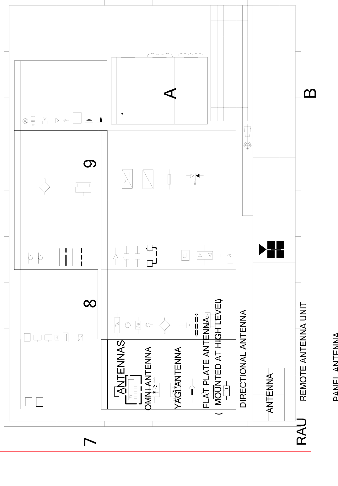
6.2 AFL RF Module Drawing Key

Maintenance Handbook
Baltimore Radio Repeater System
Handbook No. 60-166701HBKM Page 23 of 24
6.3 EC Declaration of Conformity
In accordance with BS EN ISO/IEC 17050-1&-2:2004
Aerial Facilities Limited
Aerial House
Asheridge Road
Chesham
Buckinghamshire HP5 2QD
United Kingdom
DECLARES, UNDER OUR SOLE RESPONSIBILITY THAT THE FOLLOWING PRODUCT:
PRODUCT PART NO[S] 60-166701
PRODUCT DESCRIPTION Baltimore Transit radio repeaters
IN ACCORDANCE WITH THE FOLLOWING DIRECTIVES:
1999/5/EC The Radio & Telecommunications Terminal Equipment Directive Annex V and
its amending directives
HAS BEEN DESIGNED AND MANUFACTURED TO THE FOLLOWING STANDARD[S] OR OTHER
NORMATIVE DOCUMENT[S]:
BS EN 60950 Information technology equipment.
Safety. General requirements
ETS EN 301 489-1 EMC standard for radio equipment and services.
Part 1. Common technical requirements
I hereby declare that the equipment named above has been designed to comply with the relevant
sections of the above referenced specifications. The unit complies with all essential requirements of
the Directives.
SIGNED
B S BARTON
TECHNICAL DIRECTOR DATE: 16/02/2006
Registered Office: Aerial House, Asheridge Road, Chesham, Buckinghamshire, HP5 2QD England Registered No. 4042808 (England)
www.aerialfacilities.com

Maintenance Handbook
Baltimore Radio Repeater System
Handbook No. 60-166701HBKM Page 24 of 24
6.4 Amendment List Record Sheet
Issue
No. Date Incorporated
by Page Nos.
Amended Reason for new issue
A 09/02/2006 CMH 1st Draft
1 CMH 1st Issue
Document Ref:- 60-166701HBKM