PBE Europe as Axell Wireless 60-2287SERIES 60-228701 Bi-Directional Amplifier System User Manual handbook
Axell Wireless 60-228701 Bi-Directional Amplifier System handbook
UserManual.wiki
>
PBE Europe as Axell Wireless
>
60 2287SERIES User Manual
handbook
Navigation menu
Upload a User Manual
Namespaces
Wiki Guide
HTML
PDF
Info
Views
User Manual
Discussion / Help
Navigation


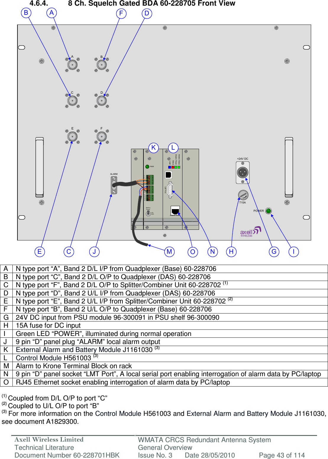
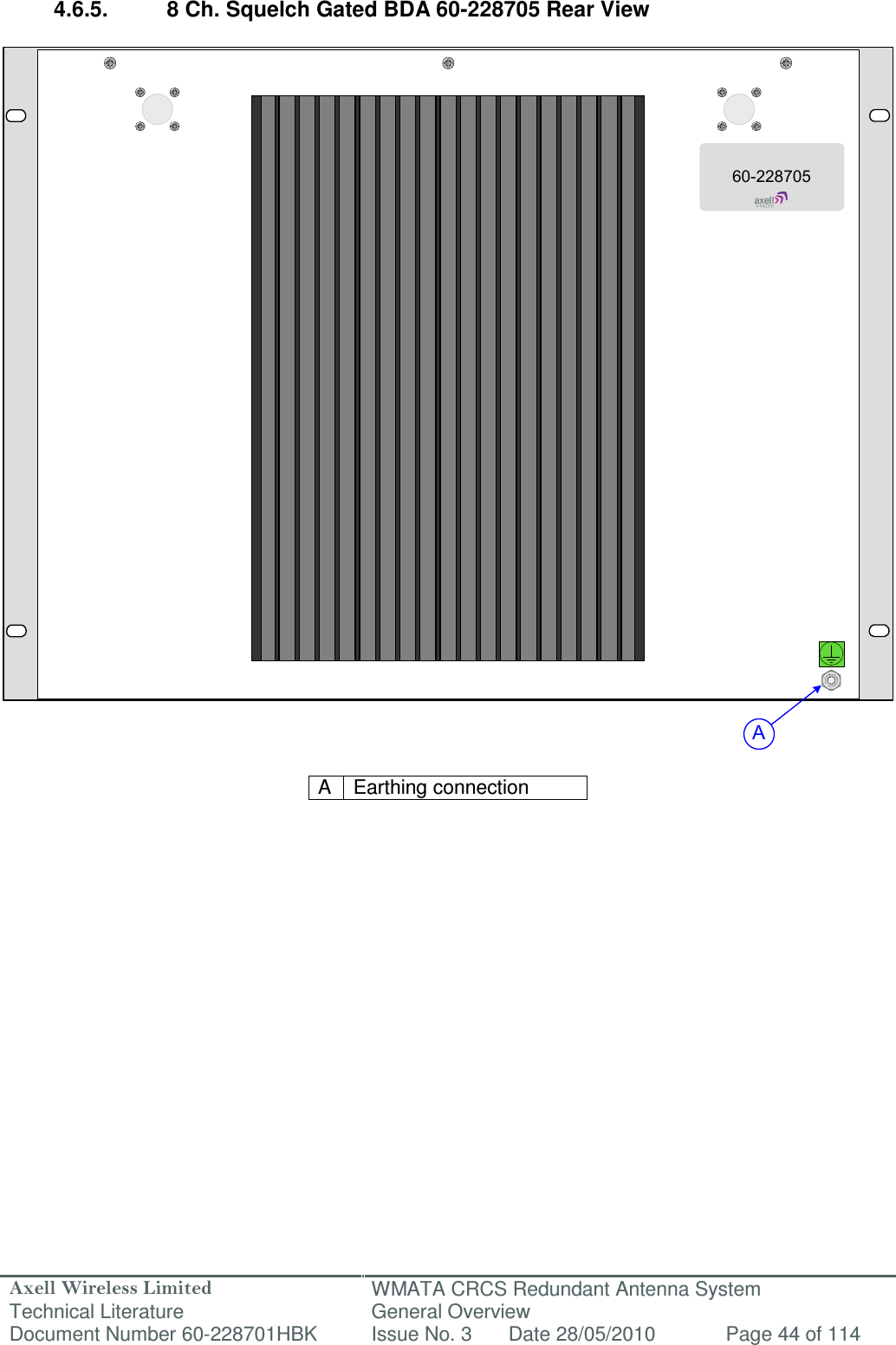
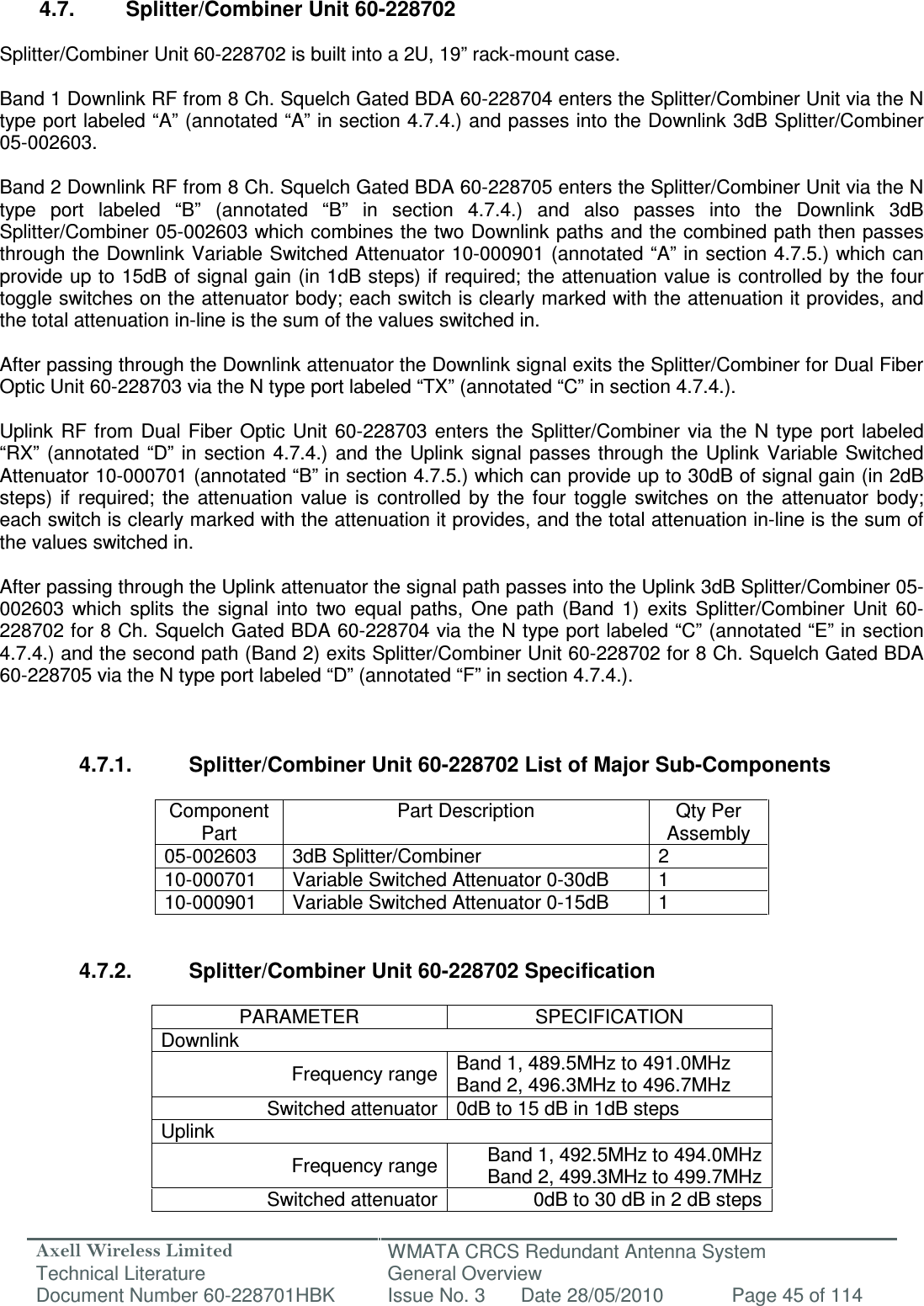
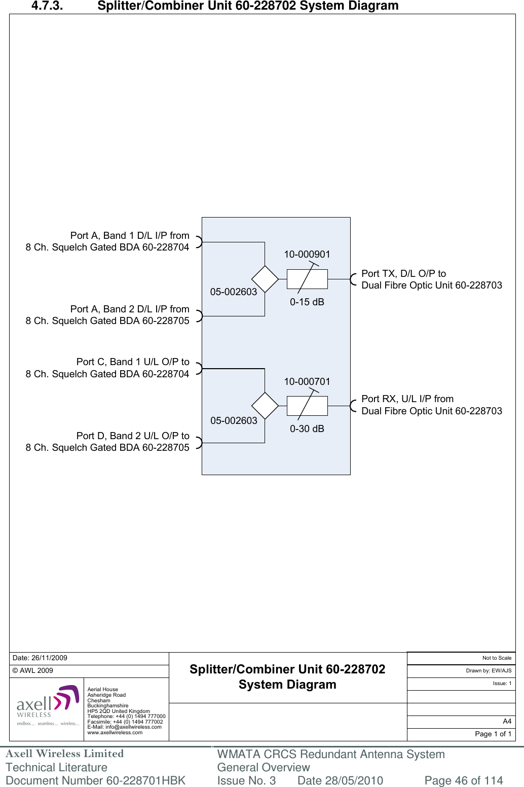


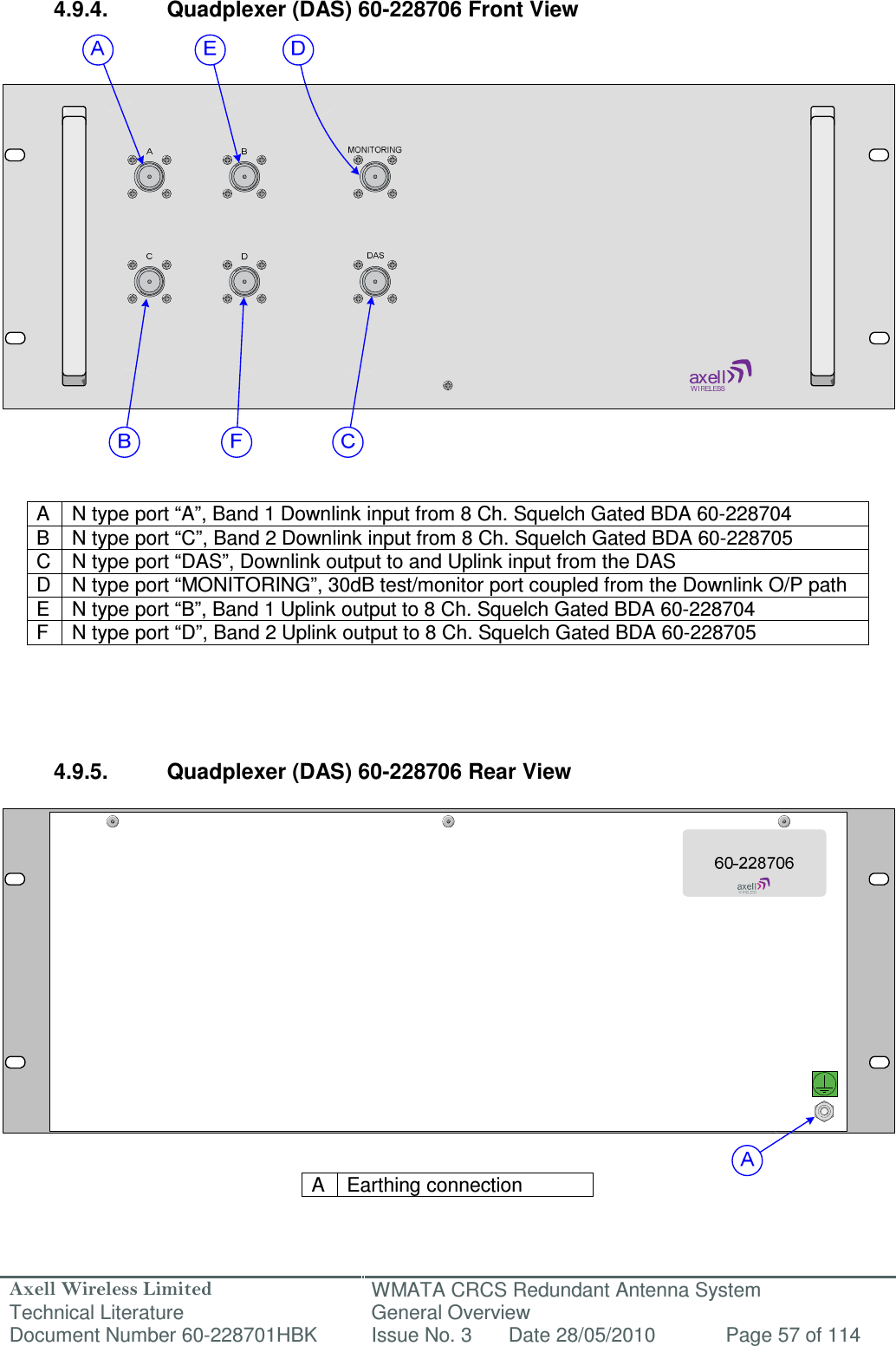
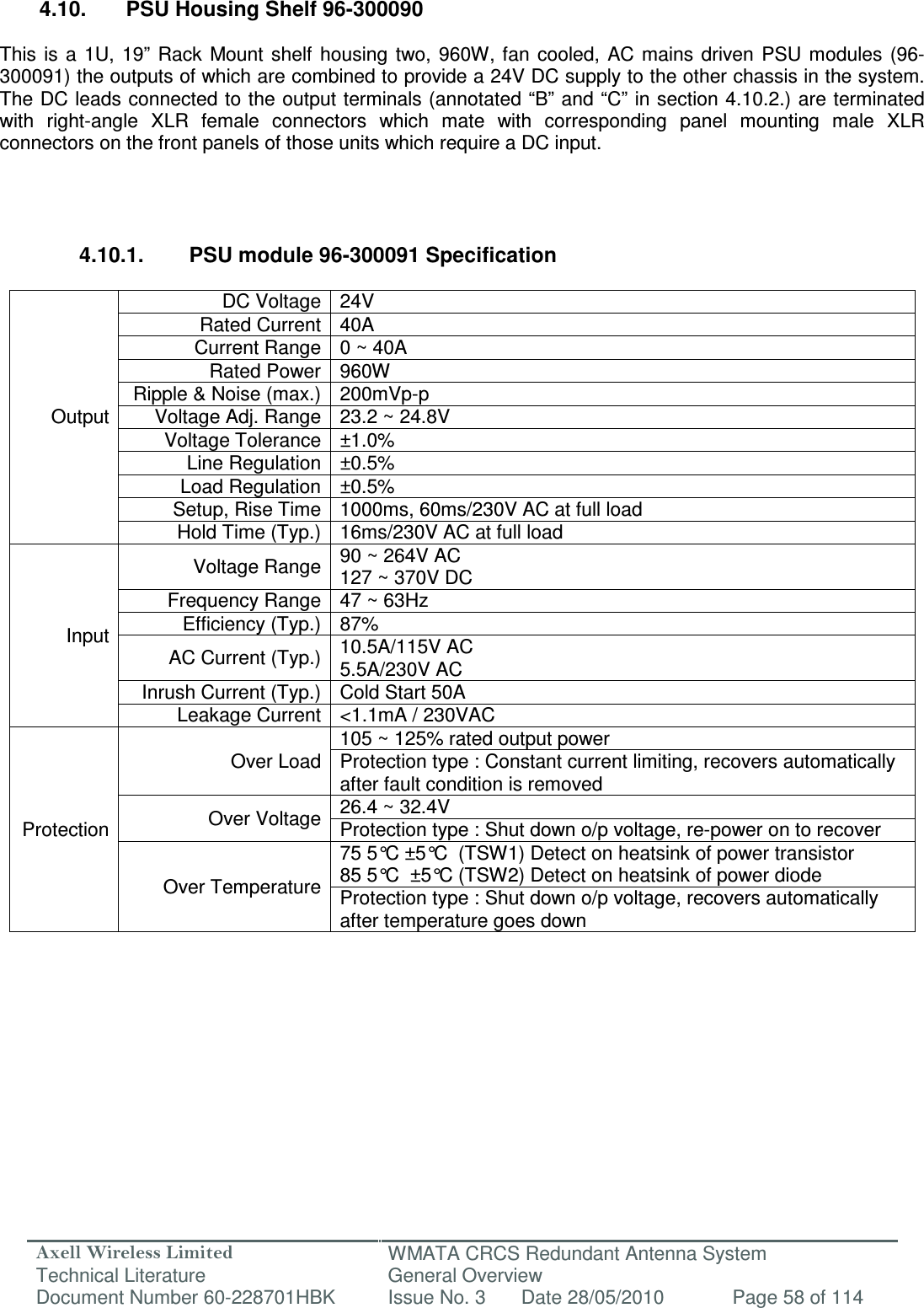
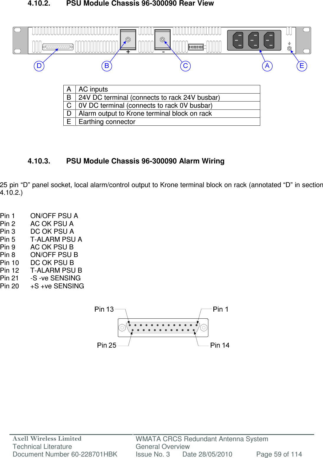
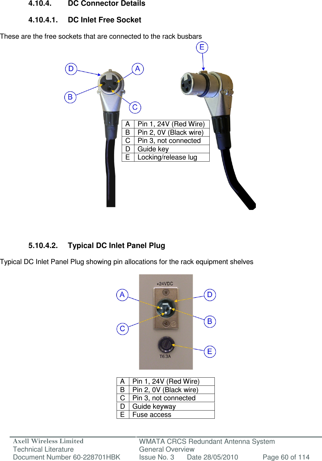


![Axell Wireless Limited Technical Literature WMATA CRCS Redundant Antenna System General Overview Document Number 60-228701HBK Issue No. 3 Date 28/05/2010 Page 112 of 114 A.3. EC Declaration of Conformity In accordance with BS EN ISO/IEC 17050-1&-2:2004 Axell Wireless Limited Aerial House Asheridge Road Chesham Buckinghamshire HP5 2QD United Kingdom Declares, under our sole responsibility that the following product: Product Part Nos. and Product Descriptions 60-228701 - WMATA Carmen Turner Facility CRAS System 60-228801 - WMATA Jackson Graham Building CRAS System 60-228901 - WMATA Gallery Place Station CRAS System In accordance with the following directives: 1999/5/EC The Radio & Telecommunications Terminal Equipment Directive Annex V and its amending directives Has been designed and manufactured to the following standard[s] or other normative document[s]: BS EN 60950 Information technology equipment. Safety. General requirements. ETS EN 301 489-1 EMC standard for radio equipment and services. Part 1. Common technical requirements. I hereby declare that the equipment named above has been designed to comply with the relevant sections of the above referenced specifications. The unit complies with all essential requirements of the Directives. SIGNED B. S. Barton Operations Director DATE: DATE: 18/11/2009 Registered Office: Aerial House, Asheridge Road, Chesham, Buckinghamshire, HP5 2QD England Registered No. 4042808 (England) www.axellwireless.com](https://usermanual.wiki/PBE-Europe-as-Axell-Wireless/60-2287SERIES/User-Guide-1299459-Page-112.png)