PBE Europe as Axell Wireless 60-2287SERIES 60-228701 Bi-Directional Amplifier System User Manual handbook
Axell Wireless 60-228701 Bi-Directional Amplifier System handbook
handbook

Axell Wireless Limited
Technical Literature
WMATA CRCS Redundant Antenna System
General Overview
Document Number 60-228701HBK Issue No. 3 Date 28/05/2010 Page 1 of 114
WMATA CRCS Redundant Antenna System
General Overview
Handbook
For
GPD Telecom Inc.
AWL Works Order Q119862
AWL Product Part Nos.:
60-228801 - WMATA Jackson Graham Building CRAS System
60-228701 - WMATA Carmen Turner Facility CRAS System
60-228901 - WMATA Gallery Place Station CRAS System
Axell Wireless UK
Aerial House
Asheridge Road
Chesham, Buckinghamshire
HP5 2QD, United Kingdom
Tel: + 44 (0) 1494 777000
Fax: + 44 (0) 1494 777002
info@axellwireless.com
www.axellwireless.com
Axell Wireless Sweden
Box 7139
174 07 Sundbyberg
Sweden
Tel: + 46 (0) 8 475 4700
Fax: + 46 (0) 8 475 4799

Axell Wireless Limited
Technical Literature
WMATA CRCS Redundant Antenna System
General Overview
Document Number 60-228701HBK Issue No. 3 Date 28/05/2010 Page 2 of 114
Table of Contents
1. Introduction .................................................................................................................................... 5
1.1. Scope and Purpose of Document................................................................................................... 5
1.2. Limitation of Liability Notice ............................................................................................................ 5
2. Safety Considerations .................................................................................................................... 6
2.1. Earthing of Equipment .................................................................................................................... 6
2.2. Electric Shock Hazard .................................................................................................................... 6
2.3. RF Radiation Hazard ...................................................................................................................... 6
2.4. Lifting and other Health and Safety Recommendations .................................................................. 6
2.5. Chemical Hazard ........................................................................................................................... 7
2.6. Laser Safety ................................................................................................................................... 7
2.7. Emergency Contact Numbers ........................................................................................................ 7
3. 60-228801 - WMATA Jackson Graham Building CRAS System ..................................................... 8
3.1. 60-228801 List of Major Sub-Components ..................................................................................... 8
3.2. 60-228801 System Diagram ........................................................................................................... 9
3.3. Dual Fiber Optic Unit 60-228703 .................................................................................................. 10
3.3.1. Dual Fiber Optic Unit 60-228703 List of Major Sub-Components ............................................. 11
3.3.2. Dual Fiber Optic Unit 60-228703 Specification ......................................................................... 11
3.3.3. Dual Fiber Optic Unit 60-228703 System Diagram ................................................................... 12
3.3.3.1. Dual Fiber Optic Unit 60-228703 Alarm Outputs ................................................................... 13
3.3.4. Dual Fiber Optic Unit 60-228703 Front View ............................................................................ 14
3.3.5. Dual Fiber Optic Unit 60-228703 Rear View ............................................................................. 15
3.3.6. Dual Fiber Optic Unit 60-228703 DC Inlet ................................................................................ 16
3.3.6.1. Free Socket for 60-228703 DC Inlet ..................................................................................... 16
3.4. Dual Redundant PSU 60-091705 ................................................................................................. 17
3.4.1. Dual Redundant PSU 60-091705 List of Major Sub-Components ............................................ 17
3.4.2. Dual Redundant PSU 60-091705 Specification ........................................................................ 17
3.4.3. Dual Redundant PSU 60-091705 System Diagram .................................................................. 18
3.4.4. Dual Redundant PSU 60-091705 Front View ........................................................................... 19
3.4.5. Dual Redundant PSU 60-091705 Rear View ............................................................................ 19
4. 60-228701 - WMATA Carmen Turner Facility CRAS System ....................................................... 20
4.1. 60-228701 List of Major Sub-Components ................................................................................... 21
4.2. 60-228701 System Diagram ......................................................................................................... 22
4.3. 60-228701 Rack Elevations ......................................................................................................... 23
4.3.1 Rack Front View ....................................................................................................................... 23
4.3.2. Rack Rear View ....................................................................................................................... 24
4.3.3. Ports on the Rack Lid ............................................................................................................... 25
4.3.4. 60-228701 Alarm Wiring Schematic ......................................................................................... 26
4.4. Quadplexer (Base) 60-228706 ..................................................................................................... 27
4.4.1. Quadplexer (Base) 60-228706 Major Sub-Components ........................................................... 28
4.4.2. Quadplexer (Base) 60-228706 Specification ............................................................................ 28
4.4.3. Quadplexer (Base) 60-228706 System Diagram ...................................................................... 29
4.4.4. Quadplexer (Base) 60-228706 Front View ............................................................................... 30
4.4.5. Quadplexer (Base) 60-228706 Rear View ................................................................................ 30
4.5. 8 Channel Squelch Gated BDA 60-228704 .................................................................................. 31
4.5.1. 8 Ch. Squelch Gated BDA 60-228704 List of Major Sub-Components ..................................... 32
4.5.2. 8 Ch. Squelch Gated BDA 60-228704 Specification ................................................................. 32
4.5.3. 8 Ch. Squelch Gated BDA 60-228704 System Diagram ........................................................... 34
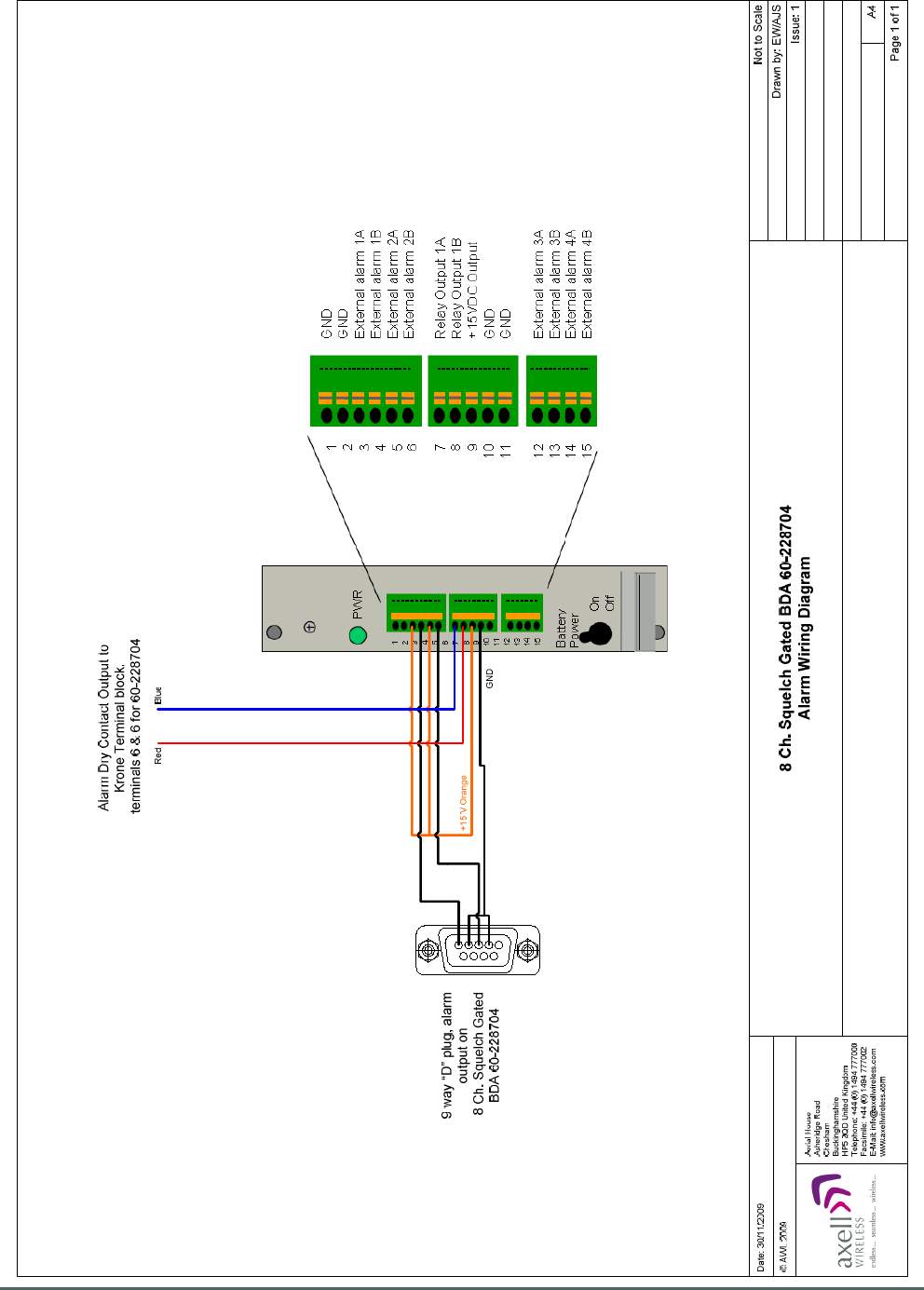
4.5.3.1 8 Ch. Squelch Gated BDA 60-228704 Alarm Wiring Diagram............................................... 35
4.5.4. 8 Ch. Squelch Gated BDA 60-228704 Front View .................................................................... 36
4.5.5. 8 Ch. Squelch Gated BDA 60-228704 Rear View ..................................................................... 37
4.6. 8 Ch. Squelch Gated BDA 60-228705 .......................................................................................... 38
4.6.1 8 Ch. Squelch Gated BDA 60-228705 List of Major Sub Components ..................................... 39

Axell Wireless Limited
Technical Literature
WMATA CRCS Redundant Antenna System
General Overview
Document Number 60-228701HBK Issue No. 3 Date 28/05/2010 Page 3 of 114
4.6.2. 8 Ch. Squelch Gated BDA 60-228705 Specification ................................................................. 39
4.6.3. 8 Ch. Squelch Gated BDA 60-228705 System Diagram ........................................................... 41
4.6.3.1. 8 Ch. Squelch Gated BDA 60-228705 Alarm Wiring Diagram............................................... 42
4.6.4. 8 Ch. Squelch Gated BDA 60-228705 Front View .................................................................... 43
4.6.5. 8 Ch. Squelch Gated BDA 60-228705 Rear View ..................................................................... 44
4.7. Splitter/Combiner Unit 60-228702 ................................................................................................ 45
4.7.1. Splitter/Combiner Unit 60-228702 List of Major Sub-Components ............................................ 45
4.7.2. Splitter/Combiner Unit 60-228702 Specification ....................................................................... 45
4.7.3. Splitter/Combiner Unit 60-228702 System Diagram ................................................................. 46
4.7.4. Splitter/Combiner Unit 60-228702 Front View .......................................................................... 47
4.7.5. Splitter/Combiner Unit 60-228702 Rear View ........................................................................... 47
4.8. Dual Fiber Optic Unit 60-228703 .................................................................................................. 48
4.8.1. Dual Fiber Optic Unit 60-228703 List of Major Sub-Components ............................................. 49
4.8.2. Dual Fiber Optic Unit 60-228703 Specification ......................................................................... 49
4.8.3. Dual Fiber Optic Unit 60-228703 System Diagram ................................................................... 50
4.8.3.1. Dual Fiber Optic Unit 60-228703 Alarm Outputs ................................................................... 51
4.8.4. Dual Fiber Optic Unit 60-228703 Front View ............................................................................ 52
4.8.5. Dual Fiber Optic Unit 60-228703 Rear View ............................................................................. 53
4.9. Quadplexer (DAS) 60-228706 ...................................................................................................... 54
4.9.1. Quadplexer (DAS) 60-228706 List of Major Sub-Components ................................................. 55
4.9.2. Quadplexer (DAS) 60-228706 Specification ............................................................................. 55
4.9.3. Quadplexer (DAS) 60-228706 System Diagram ....................................................................... 56
4.9.4. Quadplexer (DAS) 60-228706 Front View ................................................................................ 57
4.9.5. Quadplexer (DAS) 60-228706 Rear View ................................................................................. 57
4.10. PSU Housing Shelf 96-300090 .................................................................................................... 58
4.10.1. PSU module 96-300091 Specification .................................................................................. 58
4.10.2. PSU Module Chassis 96-300090 Rear View ........................................................................ 59
4.10.3. PSU Module Chassis 96-300090 Alarm Wiring .................................................................... 59
4.10.4. DC Connector Details ........................................................................................................... 60
4.10.4.1. DC Inlet Free Socket ............................................................................................................ 60
5.10.4.2. Typical DC Inlet Panel Plug .................................................................................................. 60
5. 60-228901 - WMATA Gallery Place Station CRAS System .......................................................... 61
5.1. Simplified System Sketch ............................................................................................................. 62
5.2. Rack 1 Equipment Layout ............................................................................................................ 63
5.3. Rack 2 Equipment Layout ............................................................................................................ 64
5.4. Rack 1 Front View ........................................................................................................................ 65
5.5. Rack 1 Rear View ........................................................................................................................ 66
5.6. Rack 1 elevations showing RF connections ................................................................................. 67
5.7. Rack 2 Front View ........................................................................................................................ 68
5.8. Rack 2 Rear View ........................................................................................................................ 69
5.9. Rack 2 elevations showing RF connections ................................................................................. 70
5.10. Rack Alarm Wiring Diagrams ....................................................................................................... 71
5.10.1. Rack 1 Alarm Wiring ............................................................................................................. 71
5.10.2. Rack 2 Alarm Wiring ............................................................................................................. 72
5.11 Dual Fiber Optic Unit 60-228703 (Gallery Place Station) .............................................................. 73
5.11.1. Dual Fiber Optic Unit 60-228703 List of Major Sub-Components .......................................... 74
5.11.2. Dual Fiber Optic Unit 60-228703 Specification ..................................................................... 74
5.11.3. Dual Fiber Optic Unit 60-228703 System Diagram ............................................................... 75
5.11.3.1. Dual Fiber Optic Unit 60-228703 Alarm Outputs ................................................................... 76
5.11.4. Dual Fiber Optic Unit 60-228703 Front View ........................................................................ 77
5.11.5. Dual Fiber Optic Unit 60-228703 Rear View ......................................................................... 78
5.12. RF Failover Switch Unit 60-228905 .............................................................................................. 79
5.12.1. RF Failover Switch Unit 60-228905 List of Major Sub-Components...................................... 80
5.12.2. RF Failover Switch Unit 60-228905 Specification ................................................................. 81
5.12.3. RF Failover Switch Unit 60-228905 System Diagram ........................................................... 82
5.12.4. RF Failover Switch Unit 60-228905 Alarm Wiring Diagram ................................................... 83

Axell Wireless Limited
Technical Literature
WMATA CRCS Redundant Antenna System
General Overview
Document Number 60-228701HBK Issue No. 3 Date 28/05/2010 Page 4 of 114
5.12.4.1. RF Failover Switch Unit 60-228905 Alarm Outputs ............................................................... 84
5.12.5. RF Failover Switch Unit 60-228905 Front View .................................................................... 85
5.12.6. RF Failover Switch Unit 60-228905 Rear View ..................................................................... 86
5.13. Combiner Unit 60-228906 ............................................................................................................ 87
5.13.1. Combiner Unit 60-228906 List of Major Sub-Components .................................................... 87
5.13.2. Combiner Unit 60-228906 System Diagram ......................................................................... 88
5.13.3. Combiner Unit 60-228906 Front and Rear Views ................................................................. 89
5.14. Combiner Unit 60-228908 ............................................................................................................ 90
5.14.1. Combiner Unit 60-228908 List of Major Sub-Components .................................................... 90
5.14.2. Combiner Unit 60-228908 System Diagram ......................................................................... 91
5.14.3. Combiner Unit 60-228908 Front and Rear Views ................................................................. 92
5.15. Combiner Unit 60-228909 ............................................................................................................ 93
5.15.1. Combiner Unit 60-228909 List of Major Sub-Components .................................................... 93
5.15.2. Combiner Unit 60-228909 System Diagram ......................................................................... 94
5.15.3. Combiner Unit 60-228909 Front and Rear Views ................................................................. 95
5.16. Combiner Unit 60-228907 ............................................................................................................ 96
5.16.1. Combiner Unit 60-228907 List of Major Sub-Components .................................................... 96
5.16.2. Combiner Unit 60-228907 System Diagram ......................................................................... 97
5.16.3. Combiner Unit 60-228907 Front and Rear Views ................................................................. 98
5.17. 16 Ch. DSP U/L Squelch Gate 60-228904 ................................................................................... 99
5.17.1. 16 Ch. DSP U/L Squelch Gate 60-228904 List of Major Sub-Components ........................ 100
5.17.2. 16 Ch. DSP U/L Squelch Gate 60-228904 Specification..................................................... 101
5.17.3. 16 Ch. DSP U/L Squelch Gate 60-228904 System Diagram .............................................. 102
5.17.3.1. 16 Ch. DSP U/L Squelch Gate 60-228904 Alarm Output .................................................... 103
5.17.4. 16 Ch. DSP U/L Squelch Gate 60-228904 Front View ........................................................ 104
5.17.5. 16 Ch. DSP U/L Squelch Gate 60-228904 Rear View ........................................................ 105
5.18. PSU Housing Shelf 96-300090 .................................................................................................. 106
5.18.1. PSU module 96-300091 Specification ................................................................................ 106
5.18.2. PSU Module Chassis 96-300090 Rear View ...................................................................... 107
5.18.3. PSU Module Chassis 96-300090 Alarm Wiring .................................................................. 107
5.18.4. DC Connector Details ......................................................................................................... 108
5.18.4.1. DC Inlet Free Socket .......................................................................................................... 108
5.18.4.2. Typical DC Inlet Panel Plug ................................................................................................ 108
Appendix A ................................................................................................................................................ 110
A.1. Glossary of Terms used in this document .................................................................................. 110
A.2. Key to Drawing Symbols used in this document ......................................................................... 111
A.3. EC Declaration of Conformity ..................................................................................................... 112
A.4. Waste Electrical and Electronic Equipment (WEEE) Notice ....................................................... 113
A.5. Document Amendment Record .................................................................................................. 114

Axell Wireless Limited
Technical Literature
WMATA CRCS Redundant Antenna System
General Overview
Document Number 60-228701HBK Issue No. 3 Date 28/05/2010 Page 5 of 114
1. Introduction
1.1. Scope and Purpose of Document
This handbook is for use solely with the equipment identified by the Axell Wireless Limited (AWL) Part
Number shown on the front page. It is not to be used with any other equipment unless specifically
authorized by AWL. This is a controlled release document and, as such, becomes a part of the Axell
Wireless Total Quality Management System. Alterations and modification may therefore only be performed
by Axell Wireless.
AWL recommends that the installer of this equipment familiarize themselves with the safety and installation
procedures contained within this document before installation commences.
The purpose of this handbook is to provide the user/maintainer with sufficient information to service and
repair the equipment to the level agreed. Maintenance and adjustments to any deeper level must be
performed by AWL, normally at the company’s repair facility in Chesham, England.
This handbook has been prepared in accordance with BS 4884, and AWL’s Quality procedures, which
maintain the company’s registration to BS EN ISO 9001:2000 and to the R&TTE Directive of the European
Parliament. Copies of the relevant certificates and the company Quality Manual can be supplied on
application to the Operations Support Director (see section 2.7.).
This document fulfils the relevant requirements of Article 6 of the R&TTE Directive.
1.2. Limitation of Liability Notice
This manual is written for the use of technically competent operators/service persons. No liability is
accepted by AWL for use or misuse of this manual, the information contained therein, or the consequences
of any actions resulting from the use of the said information, including, but not limited to, descriptive,
procedural, typographical, arithmetical, or listing errors.
Furthermore, AWL does not warrant the absolute accuracy of the information contained within this manual,
or its completeness, fitness for purpose, or scope.
AWL has a policy of continuous product development and enhancement, and as such, reserves the right to
amend, alter, update and generally change the contents, appearance and pertinence of this document
without notice.
Unless specified otherwise, all AWL products carry a twelve month warranty from date of shipment. The
warranty is expressly on a return-to-base repair or exchange basis and the warranty cover does not extend
to on-site repair or complete unit exchange.
Axell Wireless Limited
Technical Literature
WMATA CRCS Redundant Antenna System
General Overview
Document Number 60-228701HBK Issue No. 3 Date 28/05/2010 Page 6 of 114
2. Safety Considerations
2.1. Earthing of Equipment
Equipment supplied from the mains must be connected to grounded outlets and earthed in
conformity with appropriate local, national and international electricity supply and safety
regulations.
2.2. Electric Shock Hazard
The risk of electrical shocks due to faulty mains driven power supplies While potentially ever
present in any electrical equipment, would be minimized by adherence to good installation
practice and thorough testing at the following stages:
a) Original assembly.
b) Commissioning.
c) Regular intervals, thereafter.
All test equipment must be in good working order prior to its use. High current power supplies can be
dangerous because of the possibility of substantial arcing. Always switch off during disconnection and
reconnection.
2.3. RF Radiation Hazard
RF radiation, (especially at UHF frequencies) arising from transmitter outputs connected to
AWL’s equipment, must be considered a safety hazard.
This condition might only occur in the event of cable disconnection, or because a ‘spare’
output has been left un-terminated. Either of these conditions would impair the system’s
efficiency. No investigation should be carried out until all RF power sources have been
removed. This would always be a wise precaution, despite the severe mismatch between the impedance of
an N type connector at 50Ω, and that of free space at 377Ω, which would severely compromise the efficient
radiation of RF power. Radio frequency burns could also be a hazard, if any RF power carrying components
were to be carelessly touched!
Antenna positions should be chosen to comply with requirements (both local & statutory) regarding
exposure of personnel to RF radiation. When connected to an antenna, the unit is capable of producing RF
field strengths, which may exceed guideline safe values especially if used with antennas having appreciable
gain. In this regard the use of directional antennas with backscreens and a strict site rule that personnel
must remain behind the screen while the RF power is on, is strongly recommended.
Where the equipment is used near power lines or in association with temporary masts not having lightning
protection, the use of a safety earth connected to the case-earthing bolt is strongly advised.
2.4. Lifting and other Health and Safety Recommendations
Certain items of AWL equipment are heavy and care should be taken when lifting them by
hand. Ensure that a suitable number of personnel, appropriate lifting apparatus and
appropriate personal protective equipment is used especially when installing Equipment
above ground e.g. on a mast or pole and manual handling precautions relevant to items of
the weight of the equipment being worked on must be observed at all times when handling,
installing or dismounting this equipment.

Axell Wireless Limited
Technical Literature
WMATA CRCS Redundant Antenna System
General Overview
Document Number 60-228701HBK Issue No. 3 Date 28/05/2010 Page 7 of 114
2.5. Chemical Hazard
Beryllium Oxide, also known as Beryllium Monoxide, or Thermalox™, is sometimes used in
devices within equipment produced by Axell Wireless Ltd. Beryllium oxide dust can be toxic if
inhaled, leading to chronic respiratory problems. It is harmless if ingested or by contact.
Products that contain beryllium are load terminations (dummy loads) and some power
amplifiers. These products can be identified by a yellow and black “skull and crossbones” danger symbol
(shown above). They are marked as hazardous in line with international regulations, but pose no threat
under normal circumstances. Only if a component containing beryllium oxide has suffered catastrophic
failure, or exploded, will there be any danger of the formation of dust. Any dust that has been created will be
contained within the equipment module as long as the module remains sealed. For this reason, any module
carrying the yellow and black danger sign should not be opened. If the equipment is suspected of failure, or
is at the end of its life-cycle, it must be returned to Axell Wireless Ltd. for disposal.
To return such equipment, please contact the Operations Support Department, who will give you a Returned
Materials Authorization (RMA) number. Please quote this number on the packing documents, and on all
correspondence relating to the shipment.
Polytetrafluoroethylene, (P.T.F.E.) and P.T.F.E. Composite Materials
Many modules/components in AWL equipment contain P.T.F.E. as part of the RF insulation barrier.
This material should never be heated to the point where smoke or fumes are evolved. Any person feeling
drowsy after coming into contact with P.T.F.E., especially dust or fumes should seek medical attention.
2.6. Laser Safety
General good working practices adapted from
EN60825-2: 2004/ EC 60825-2:2004
Do not stare with unprotected eyes or with any unapproved optical device at the fiber ends or
connector faces or point them at other people, Use only approved filtered or attenuating
viewing aids.
Any single or multiple fiber end or ends found not to be terminated (for example, matched, spliced) shall be
individually or collectively covered when not being worked on. They shall not be readily visible and sharp
ends shall not be exposed.
When using test cords, the optical power source shall be the last connected and the first disconnected; use
only approved methods for cleaning and preparing optical fibers and optical connectors.
Always keep optical connectors covered to avoid physical damage and do not allow any dirt/foreign material
ingress on the optical connector bulkheads.
The optical fiber jumper cable minimum bend radius is 3cm; bending to a smaller radius may result in optical
cable breakage and excessive transmission losses.
Caution: The F/O units are NOT weather proof.
2.7. Emergency Contact Numbers
The AWL Operations Support Department can be contacted on:
Telephone +44 (0)1494 777000
Fax. +44 (0)1494 777002
e-mail qa@axellwireless.com

Axell Wireless Limited
Technical Literature
WMATA CRCS Redundant Antenna System
General Overview
Document Number 60-228701HBK Issue No. 3 Date 28/05/2010 Page 8 of 114
3. 60-228801 - WMATA Jackson Graham Building CRAS System
The WMATA Jackson Graham Building CRAS System consists of the following equipment:
Part No. 60-228703 Dual Fiber Optic Unit
Part No. 60-091705 Dual Redundant PSU
The Jackson Graham Building CRAS System provides the Primary Downlink to and receives the Primary
Uplink signal from the Gallery Place Station CRAS System.
The Downlink signal is received from a BTS via a direct connection and is modulated onto an optical signal
which is then fed to the Gallery Place Station CRAS System via fiber optic cables. This Downlink is the
Primary Downlink from the Jackson Graham Building CRAS System to the Gallery Place Station CRAS
System.
Uplink optical signals from the Gallery Place Station CRAS System are received via fiber optic cables,
demodulated to RF and fed to the BTS. This Uplink is the Primary Uplink from the Gallery Place Station
CRAS System to the Jackson Graham Building CRAS System.
Provision is made for a redundant standby path in both the Downlink and Uplink, these are referred to as the
“Main Primary” and “Standby Redundant” paths.
3.1. 60-228801 List of Major Sub-Components
Component
Part
Component Part Description Qty Per
Assembly
60-228703 Dual Fiber Optic Unit 1
60-091705 Dual Redundant PSU 1
Axell Wireless Limited
Technical Literature
WMATA CRCS Redundant Antenna System
General Overview
Document Number 60-228701HBK Issue No. 3 Date 28/05/2010 Page 9 of 114
Date: 15/02/2010
© AWL 2010
Page 1 of 1
A4
Issue: 2
Drawn by: EW/AJS
Not to Scale
Aerial House
Asheridge Road
Chesham
Buckinghamshire
HP5 2QD United Kingdom
Telephone: +44 (0) 1494 777000
Facsimile: +44 (0) 1494 777002
E-Mail: info@axellwireless.com
www.axellwireless.com
Jackson Graham Building
CRAS System Diagram
Port TX1 D/L I/P
TX1 Monitor
Port TX2 D/L I/P
TX2 Monitor
Port RX1 U/L O/P
RX1 Monitor
RX2 Monitor
Port RX2 U/L O/P
+24V DC +12V DC
DC I/P
Dual Fibre Optic Unit 60-228703
AC INPUT
12V DC
Outputs
Dual Redundant PSU Shelf 60-091705
Optical Port 1 “TX”
D/L O/P
Optical Port 1 “RX”
U/L I/P
Optical Port 2 “TX”
D/L O/P
Optical Port 2 “RX”
U/L I/P
3.2. 60-228801 System Diagram

Axell Wireless Limited
Technical Literature
WMATA CRCS Redundant Antenna System
General Overview
Document Number 60-228701HBK Issue No. 3 Date 28/05/2010 Page 10 of 114
3.3. Dual Fiber Optic Unit 60-228703
Dual Fiber Optic Unit 60-228703 is built into a 2U, 19” rack-mount case.
The Main Primary Downlink RF path from the BTS enters the Dual Fiber Optic Unit via the N type port
labeled “TX 1” (annotated “A” in section 3.3.4.) and then passes through a 20dB Directional Coupler 90-
852420 which couples off a small portion of the signal and feeds it to the N type port labeled “MON -20dB
TX 1” (annotated “B” in section 3.3.4.) which provides a 20dB test/monitor port for the Main Primary
Downlink input.
The Main Primary Downlink path then passes into a Fiber Optic Transmitter Module 20-005401 where the
RF signal is modulated onto a laser and the optical signal thus produced then exits the Dual Fiber Optic Unit
via the SC/APC optical port 1 “TX” (annotated “C” in section 3.3.4.) and is transmitted to the Gallery Place
Station CRAS System via a fiber optic cable link.
The N type port labeled “TX 2” (annotated “D” in section 3.3.4..) is a Downlink input to a separate, parallel,
Standby Redundant Downlink path with its own Directional Coupler, test monitor port (annotated “E” in
section 3.3.4.) and Fiber Optic Transmitter Module. The Optical output from the Standby Redundant
Downlink path exits the Dual Fiber Optic Unit via the SC/APC optical port 2 “TX” (annotated “F” in section
3.3.4.)
Switching between the Main and Standby Redundant Downlink paths is accomplished manually by
disconnecting the Downlink RF input from the “TX 1” port and connecting it to the “TX 2” port, and by
disconnecting the optical Downlink output cable from the SC/APC optical port 1 “TX” and connecting it to the
SC/APC optical port 2 “TX” N.B. The safety precautions noted in section 2 must be observed when
changing from main to standby.
The Main Primary Uplink optical signal from the Gallery Place Station CRAS System enters the Dual Fiber
Optic Unit via the SC/APC optical port 1 “RX” (annotated “G” in section 3.3.4.) and passes into a Fiber Optic
Receiver Module 20-005501 which demodulates the Uplink signal to RF and the Uplink RF signal then
passes through a 20dB Directional Coupler 90-852420 which couples off a small portion of the signal and
feeds it to the N type port labeled “MON -20dB RX 1” (annotated “I” in section 3.3.4.) which provides a 20dB
test/monitor port for the Main Primary Uplink output. The Main Primary Uplink path then exits the Dual Fiber
Optic Unit for the BTS via the N type port labeled “RX 1” (annotated “H” in section 3.3.4.)
The SC/APC optical port 2 “RX” (annotated “J” in section 3.3.4.) is an Uplink input to a separate, parallel,
Standby Redundant Uplink path with its own Fiber Optic Receiver Module, Directional Coupler and
test/monitor port (annotated “L” in section 3.3.4.) The RF output from the standby Uplink path exits the Dual
Fiber Optic Unit for the BTS via the N type port labeled “RX 2” (annotated “K” in section 3.3.4.)
Switching between the Main and Standby Redundant Uplink paths is accomplished manually by
disconnecting the optical Uplink input cable from the SC/APC optical port 1 “RX” and connecting it to the
SC/APC optical port 2 “RX”, and by disconnecting the Uplink RF output from the “RX 1” port and connecting
it to the “RX 2” port. N.B. The safety precautions noted in section 2 must be observed when changing from
main to standby.
Dual Fiber Optic Unit 60-228703 is powered by a 12V DC supply from Dual Redundant PSU 60-091705,
which powers the fiber optic modules within the unit
An alarm system is fitted to Dual Fiber Optic Unit 60-228703, each of the fiber optic modules carries its own
voltage-free contact alarm relay output which are summed at the 15 way “D” panel plug labeled “ALARM”
(annotated “EE” in section 3.3.4.)

Axell Wireless Limited
Technical Literature
WMATA CRCS Redundant Antenna System
General Overview
Document Number 60-228701HBK Issue No. 3 Date 28/05/2010 Page 11 of 114
3.3.1. Dual Fiber Optic Unit 60-228703 List of Major Sub-Components
Component
Part
Part Description Qty Per
Assembly
20-001601 12V Dual Relay Board 1
20-005401 Fiber Optic Transmitter Module 2
20-005501 Fiber Optic Receiver Module 2
96-110013 3.15 A Fuse 2
96-200024 DC/DC Converter 2
90-852420 20dB Directional Coupler 4
94-100003 Power Diode 3
3.3.2. Dual Fiber Optic Unit 60-228703 Specification
PARAMETER SPECIFICATION
RF Downlink
Frequency range
489.5MHz to 491.0MHz
496.3MHz to 496.7MHz
Coupling TX1 to Mon TX1
20 dB±1
Coupling TX2 to Mon TX2
20 dB±1
Optical Downlink
Wavelength
1310nm
TX(A) Optical TX Power
1-3 dBm
TX(B) Optical TX Power
1-3 dBm
Optical Uplink
Wavelength
1550nm
RX(A) Gain
>+15 dB
RX(A) Gain Set To
0 dB±0.5
RX(A) Alarm Threshold
< -10dBm
RX(B) Gain
>+15 dB
RX(A) Gain Set To
0 dB±0.5
RX(B) Alarm Threshold
< -10dBm
RF Uplink
Frequency range
499.3MHz to 499.7MHz
492.5MHz to 494.0MHz
Coupling RX1 to Mon RX1
20 dB±1
Coupling RX2 to Mon RX2
20 dB±1
General
Supply Voltage
12V DC or 24V DC
Current consumption
< 1.0A @ 24V DC input
< 1.5A @ 12V DC input
Alarm output
Summary volts free dry contact output
(Closed = Normal / Open = Alarm)
F/O TX1 contact output Pin 1 & 2
F/O TX2 contact output Pin 3 & 4
F/O RX1 contact output Pin 5 & 6
F/O RX1 contact output Pin 7 & 8
24V DC-DC contact output Pin 9 & 10**
**This alarm is not operational when the unit is powered from 12V DC
Axell Wireless Limited
Technical Literature
WMATA CRCS Redundant Antenna System
General Overview
Document Number 60-228701HBK Issue No. 3 Date 28/05/2010 Page 12 of 114
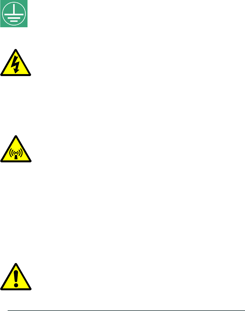
20-005401
20-005501
20-001601
Local Alarm
TX1 Monitor
TX2 Monitor
RX1 Monitor
RX2 Monitor
20-005401
20-005501
90-852420
90-852420
90-852420
90-852420
+24 VDC
2 x
96-200024
+12 VDC
3 x
94-100003
DC I/P
Port TX1 Main Primary D/L I/P
Port TX2 Standby Redundant D/L I/P
Port RX1 Main Primary U/L O/P
Port RX2 Standby Redundant U/L O/P
Optical Port 1 “TX”
Main Primary D/L O/P to
Gallery Place Station CRAS system
Optical Port 1 “RX”
Main Primary U/L I/P from
Gallery Place Station CRAS system
Optical Port 2 “TX”
Standby Redundant D/L O/P to
Gallery Place Station CRAS system
Optical Port 2 “RX”
Standby Redundant U/L I/P from
Gallery Place Station CRAS system
Dual Fibre Optic Unit 60-228703
System Diagram
(Jackson Graham Building CRAS System)
Date: 15/02/2010
Aerial House
Asheridge Road
Chesham
Buckinghamshire
HP5 2QD
United Kingdom
© AWL 2010
Page 1 of 1
A4
Issue: 3
Drawn by: EW/AJS
Not to Scale
Telephone: +44 (0) 1494 777000
Facsimile: +44 (0) 1494 777002
E-Mail: info@axellwireless.com
www.axellwireless.com
3.3.3. Dual Fiber Optic Unit 60-228703 System Diagram
Axell Wireless Limited
Technical Literature
WMATA CRCS Redundant Antenna System
General Overview
Document Number 60-228701HBK Issue No. 3 Date 28/05/2010 Page 13 of 114
3.3.3.1. Dual Fiber Optic Unit 60-228703 Alarm Outputs
15 pin “D” panel plug “ALARM”, local alarm output to Krone terminal block on rack (annotated “EE” in
section 3.3.3.)
Dry Contact Outputs (Closed = Normal / Open = Alarm)
F/O TX 1 (main), contact output Pin 1 & 2
F/O TX 2 (standby), contact output Pin 3 & 4
F/O RX 1 (main), contact output Pin 5 & 6
F/O RX 2 (standby), contact output Pin 7 & 8
24V DC>DC contact output Pin 9 & 10
Axell Wireless Limited
Technical Literature
WMATA CRCS Redundant Antenna System
General Overview
Document Number 60-228701HBK Issue No. 3 Date 28/05/2010 Page 14 of 114
TX RX
TX RX
1
2
POWER
ALARM
GAIN ADJ
POWER
ALARM
POWER
ALARM
POWER
ALARM
GAIN ADJ
MON
-20dB TX 1
MON
-20dB RX 1
MON
-20dB RX 2
MON
-20dB TX 2
TX 1 RX 1
TX 2 RX 2 TX 1 RX 1 TX 2 RX 2
DC/DC FAIL
ALARM
24V T3.15A12V T3.15A
+24/12V DC
B
D
C A
EF
G HI
L KJ M
O
N
P
R
Q
W
Y
X Z
U
T V
S
AA
BBCC
DD
EE
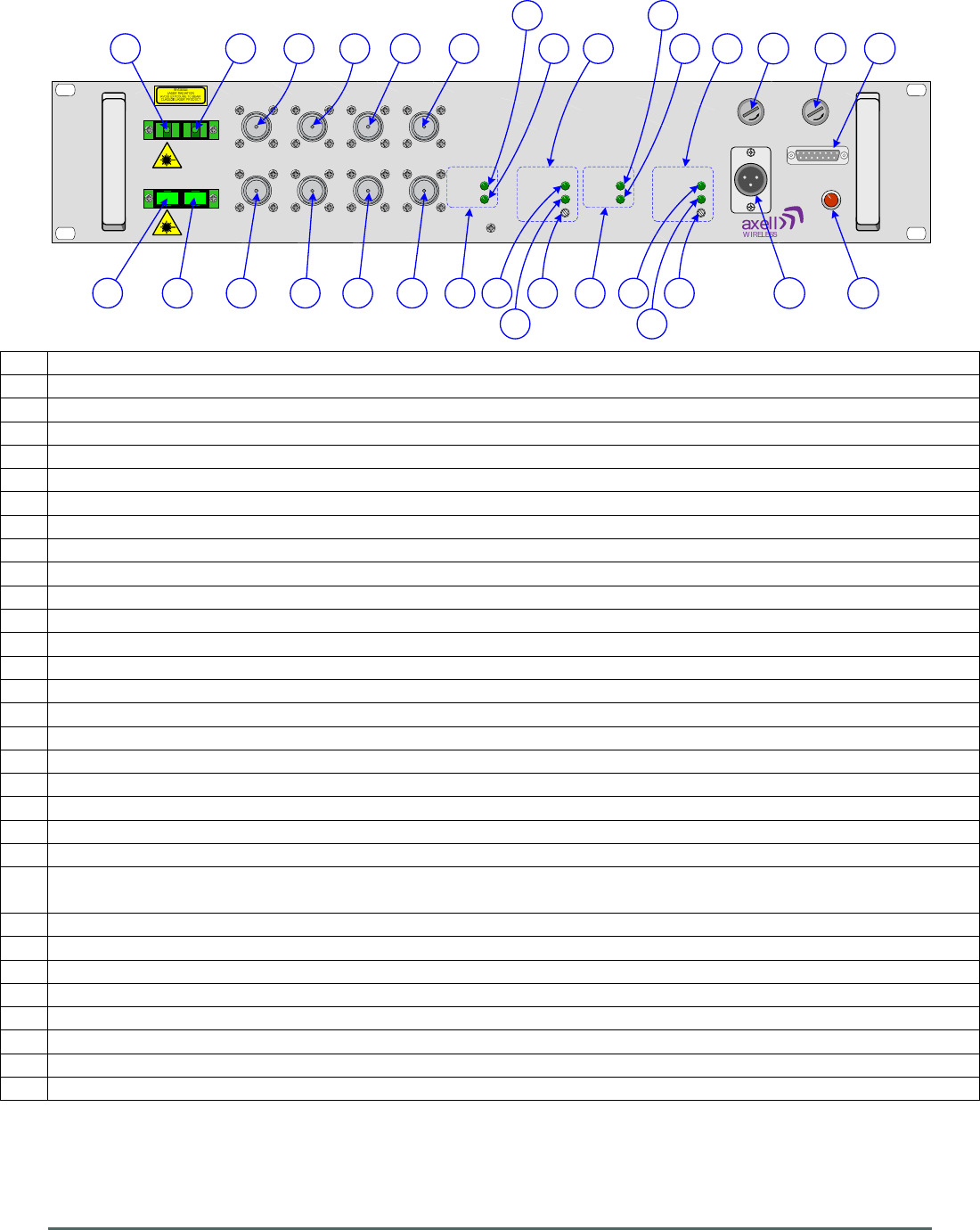
3.3.4. Dual Fiber Optic Unit 60-228703 Front View
A N type port “TX1”, Main Primary RF D/L I/P from BTS
B N type port “MON -20dB TX 1”, 20dB test/monitor port coupled from D/L input to port “TX1”
C SC/APC optical port 1 “TX”, Main Primary optical D/L O/P to Gallery Place Station CRAS System
D N type port “TX2”, Standby Redundant RF D/L I/P from BTS
E N type port “MON -20dB TX 2”, 20dB test/monitor port coupled from D/L input to port “TX2”
F SC/APC optical port 2 “TX”, Standby Redundant optical D/L O/P to Gallery Place Station CRAS System
G SC/APC optical port 1 “RX”, Main Primary optical U/L I/P from Gallery Place Station CRAS System
H N type port “RX1”, Main Primary RF U/L O/P to BTS
I N type port “MON -20dB RX 1”, 20dB test/monitor port coupled from U/L output to port “RX1”
J SC/APC optical port 2 “RX”, standby optical U/L I/P from Gallery Place Station CRAS System
K N type port “RX2”, Standby Redundant RF U/L O/P to BTS
L N type port “MON -20dB RX 2”, 20dB test/monitor port coupled from U/L output to port “RX2”
M Status Indicators for F/O TX Module 1 (Main Primary D/L to Gallery Place Station CRAS System)
N Green LED “POWER”, Fiber Optic TX Power On indicator illuminated during normal operation
O Green LED “ALARM”, Fiber Optic TX Alarm indicator extinguished during alarm state
P Status Indicators for F/O TX Module 2 (Standby Redundant D/L to Gallery Place Station CRAS System)
Q Green LED “POWER”, Fiber Optic TX Power On indicator illuminated during normal operation
R Green LED “ALARM”, Fiber Optic TX Alarm indicator extinguished during alarm state
S Status Indicators for F/O RX Module 1 (Main Primary U/L from Gallery Place Station CRAS System)
T Green LED “POWER”, Fiber Optic RX Power On indicator illuminated during normal operation
U Green LED “ALARM”, Fiber Optic RX Alarm indicator extinguished during alarm state
V Fiber Optic RX RF gain adjustment
W Status Indicators for F/O RX Module 2 (Standby Redundant U/L from Gallery Place Station CRAS
System)
X Green LED “POWER”, Fiber Optic RX Power On indicator illuminated during normal operation
Y Green LED “ALARM”, Fiber Optic RX Alarm indicator extinguished during alarm state
Z Fiber Optic RX RF gain adjustment
AA DC input (12V or 24V)
BB 3.15A Fuse for 24V DC input
CC
3.15A Fuse for 12V DC input
DD
Red LED “DC/DC FAIL” illuminated in alarm state (DC/DC convertor failure)
EE 15 pin “D” panel plug “ALARM” local alarm output

Axell Wireless Limited
Technical Literature
WMATA CRCS Redundant Antenna System
General Overview
Document Number 60-228701HBK Issue No. 3 Date 28/05/2010 Page 15 of 114
3.3.5. Dual Fiber Optic Unit 60-228703 Rear View
A Earthing connection
Axell Wireless Limited
Technical Literature
WMATA CRCS Redundant Antenna System
General Overview
Document Number 60-228701HBK Issue No. 3 Date 28/05/2010 Page 16 of 114
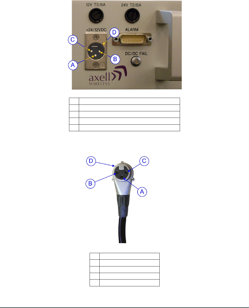
3.3.6. Dual Fiber Optic Unit 60-228703 DC Inlet
The Dual Fiber Optic Unit 60-228703 is a standard module used in three different locations: the Jackson
Graham Building, the Carmen Turner Facility and the Gallery Place Station. The DC supply voltage
available at the Carmen Turner Facility and the Gallery Place Station locations is 24V While the DC supply
at the Jackson Graham Building is 12V so to enable the provision of a standardized unit the Dual Fiber
Optic Unit 60-228703 is configured to operate from both 24V and 12V DC supplies
A Pin 3, 12V, (Red Wire)
B Pin 2, 0V, (Black wire)
C Pin 1, not connected (used for 24V I/P)
D Guide keyway
E Fuse access
3.3.6.1. Free Socket for 60-228703 DC Inlet
A Pin 3, 12V (Red Wire)
B Pin 2, 0V (Black wire)
C
Pin 1, not connected
D
Guide key
E Locking/release lug

Axell Wireless Limited
Technical Literature
WMATA CRCS Redundant Antenna System
General Overview
Document Number 60-228701HBK Issue No. 3 Date 28/05/2010 Page 17 of 114
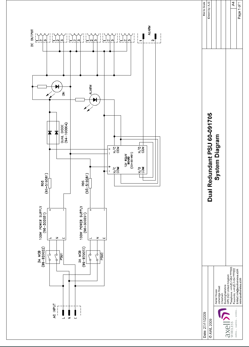
3.4. Dual Redundant PSU 60-091705
Dual Redundant PSU 60-091705 is built into a 4U, 19” rack-mount case.
The PSU case houses two mains driven PSU modules whose outputs are parallel combined using high
power, low volt-drop diodes. This means that if either supply fails the other will seamlessly take over all
power provision until the fault is rectified. Both supplies’ outputs are monitored and an alarm will become
active should either module fail.
3.4.1. Dual Redundant PSU 60-091705 List of Major Sub-Components
Component
Part
Part Description Qty Per
Assembly
20-001601 12V Dual Relay Board 1
94-100004 Dual Diode Assembly 1
96-300051 100W PSU Module 2
96-920022 3A Circuit Breaker 2
3.4.2. Dual Redundant PSU 60-091705 Specification
PARAMETER SPECIFICATION
Input
115/230V AC 50/60Hz (nominal, single port)
Outputs
6 x 12V DC at 16A (max. total)
Indicators
Green ‘DC on’ LED
Red LED (alarm1)
Alarm Interface
9-way ‘D’ connector
PSU1 alarm
pins 1 & 2
PSU2 alarm
Pins 1 & 4
Axell Wireless Limited
Technical Literature
WMATA CRCS Redundant Antenna System
General Overview
Document Number 60-228701HBK Issue No. 3 Date 28/05/2010 Page 18 of 114
3.4.3. Dual Redundant PSU 60-091705 System Diagram
Axell Wireless Limited
Technical Literature
WMATA CRCS Redundant Antenna System
General Overview
Document Number 60-228701HBK Issue No. 3 Date 28/05/2010 Page 19 of 114
POWER
ALARM
A B
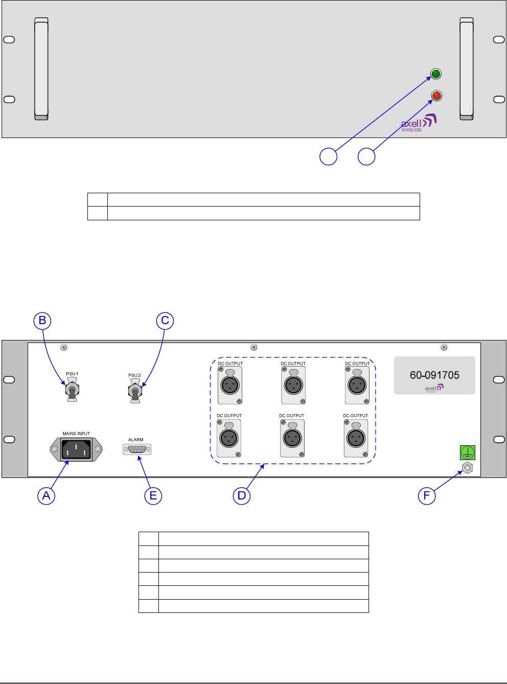
3.4.4. Dual Redundant PSU 60-091705 Front View
A Green LED “POWER”, illuminated during normal operation
B Red LED “ALARM”, illuminated during alarm condition
3.4.5. Dual Redundant PSU 60-091705 Rear View
A AC Mains input
B Trip switch for PSU module 1
C
Trip switch for PSU module 2
D
12V DC outputs
E 9 way “D” panel plug, alarm output
F Earthing connection

Axell Wireless Limited
Technical Literature
WMATA CRCS Redundant Antenna System
General Overview
Document Number 60-228701HBK Issue No. 3 Date 28/05/2010 Page 20 of 114
4. 60-228701 - WMATA Carmen Turner Facility CRAS System
The WMATA Carmen Turner Facility CRAS System consists of the following equipment mounted in a 41U,
19” equipment housing rack
Part No. 96-300090 PSU Housing Shelf
Contains Qty. 2, Part No. 96-300091 PSU Modules
Part No. 60-228703 Dual Fiber Optic Unit
Part No. 60-228702 Splitter/Combiner Unit
Part No. 60-228706 Quadplexer (Base)
Part No. 60-228706 Quadplexer (DAS)
Part No. 60-228704 8 Ch. Squelch Gated BDA (Band 1)
Part No. 60-228705 8 Ch. Squelch Gated BDA (band 2)
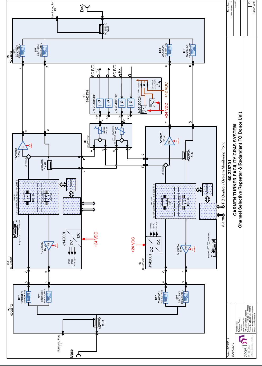
The Carmen Turner Facility CRAS System provides the Redundant Downlink to and receives the
Redundant Uplink signal from the Gallery Place Station CRAS System. In addition, the Carmen Turner
Facility CRAS System also provides a Downlink to and receives an Uplink from a local Distributed Antenna
System within the Carmen Turner Facility building
Downlink RF from a remote off-air BTS is received and the signal is split into two paths; each path consists
of a pair of frequencies, Downlink and Uplink, within the overall operating passband which can be processed
together While allowing the easy rejection of opposing frequencies. For the sake of convention, within the
Carmen Turner Facility CRAS System, the descriptions “Band 1” and “Band 2” will be used to refer to the
two Downlink and Uplink pairs according to the following table:
Band 1 Downlink 489.5MHz to 491.0MHz
Uplink 492.5MHz to 494.0MHz
Band 2 Downlink 496.3MHz to 496.7MHz
Uplink 499.3MHz to 499.7MHz
The Downlink signals are then processes utilizing SDR technology to define the eight operating channels.
and then amplified. The two paths are re-combined and then fed to the distributed antenna system.
RF Uplink from the distributed antenna system is split into two paths, for the reasons outlined above, which
are processed utilizing SDR technology to define the eight operating channels and amplified. The two paths
are then re-combined and then fed to the BTS.
In the Downlink path the signal is split by means of a directional coupler and fed to a fiber optic transmitter
which modulates the RF signal on to an optical signal which is then fed to the Gallery Place Station CRAS
System.
Optical Uplink signals from the Gallery Place Station CRAS System are received and demodulated to RF
and coupled onto the Uplink path to the remote off-air BTS.
Provision is made for a redundant standby path in both the Downlink and Uplink to and from the Gallery
Place Station CRAS System; these are referred to as the “Main Redundant” and “Standby Redundant”
paths.

Axell Wireless Limited
Technical Literature
WMATA CRCS Redundant Antenna System
General Overview
Document Number 60-228701HBK Issue No. 3 Date 28/05/2010 Page 21 of 114
4.1. 60-228701 List of Major Sub-Components
Component
Part
Component Part Description Qty Per
Assembly
60-228706
Quadplexer (Base) 1
60-228704
8 Ch. Squelch Gated BDA (Band 1) 1
60-228705
8 Ch. Squelch Gated BDA (band 2) 1
60-228702
Splitter/Combiner Unit 1
60-228703
Dual Fiber Optic Unit 2
60-228706
Quadplexer (DAS) 1
96-300090
PSU Housing Shelf 1
96-300091
PSU Module 2
97-500424
41U 19" Equipment Rack 1
Axell Wireless Limited
Technical Literature
WMATA CRCS Redundant Antenna System
General Overview
Document Number 60-228701HBK Issue No. 3 Date 28/05/2010 Page 22 of 114
Controller
H56
Alarm/Battery
Alarm
Controller
H56
Alarm/Battery
PC Control
System Monitoring Point
4.2. 60-228701 System Diagram
Axell Wireless Limited
Technical Literature
WMATA CRCS Redundant Antenna System
General Overview
Document Number 60-228701HBK Issue No. 3 Date 28/05/2010 Page 23 of 114
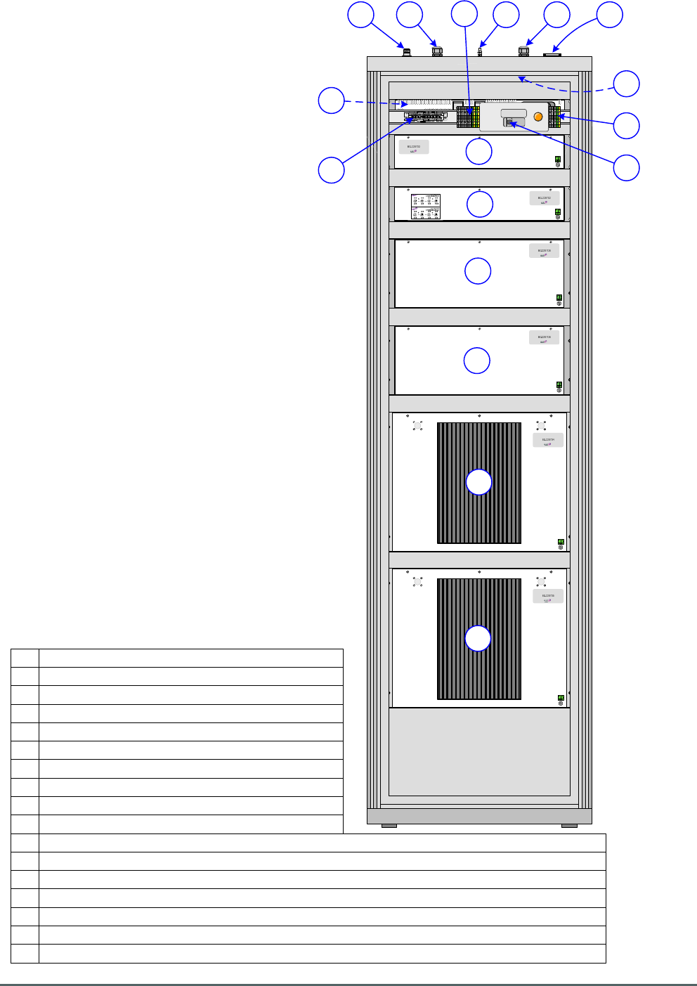
4.3. 60-228701 Rack Elevations
4.3.1 Rack Front View
A PSU Housing Shelf 96-300090
B Dual Fiber Optic Unit 60-228703
C
Splitter/Combiner Unit 60-228702
D
Quadplexer (Base) 60-228706
E Quadplexer (DAS) 60-228706
F 8 Ch. Squelch Gated BDA 60-228704
G
8 Ch. Squelch Gated BDA 60-228705
H
1U Blanking Panels
I 5U Blanking Panel
Axell Wireless Limited
Technical Literature
WMATA CRCS Redundant Antenna System
General Overview
Document Number 60-228701HBK Issue No. 3 Date 28/05/2010 Page 24 of 114
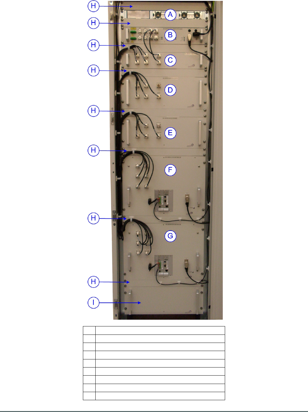
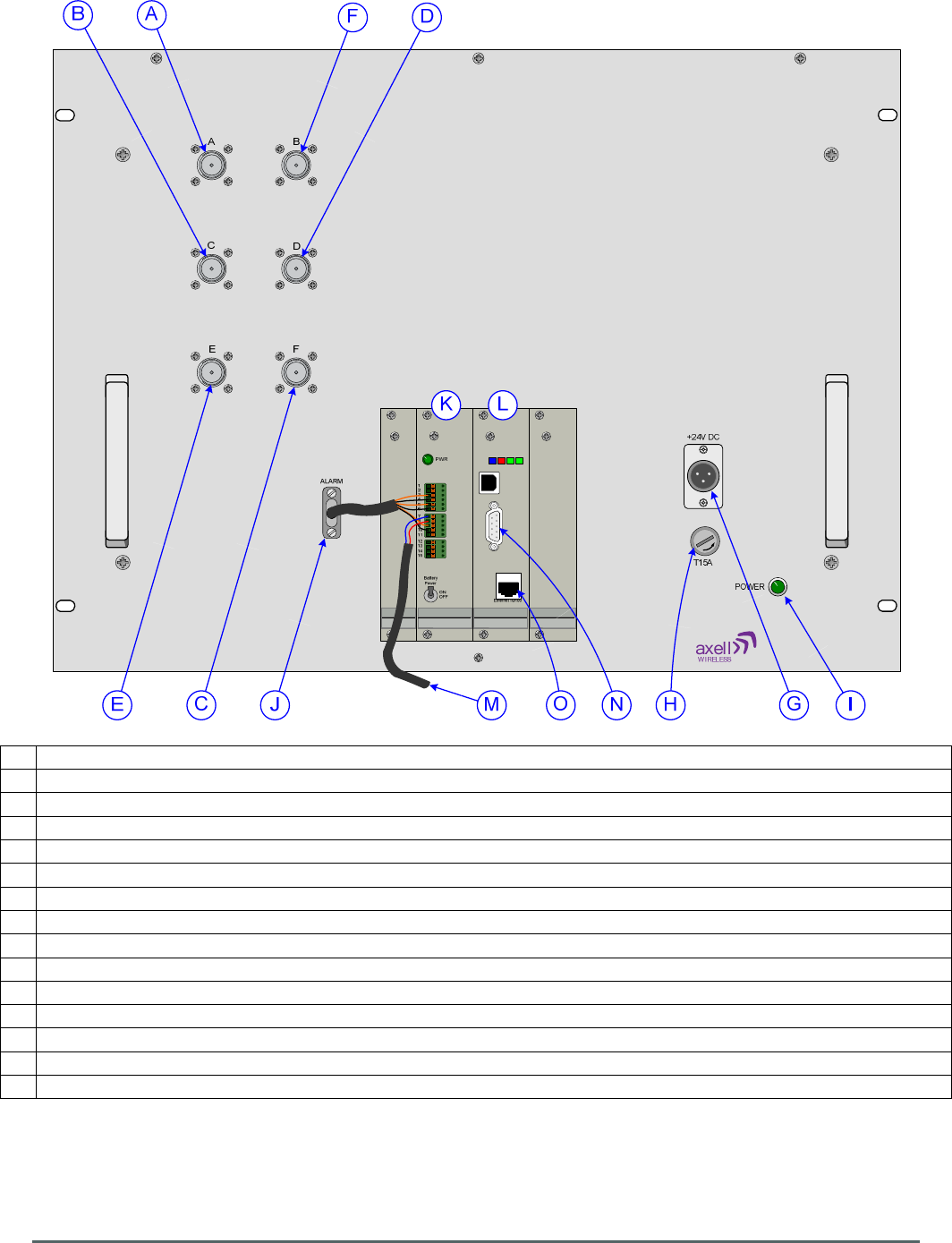
4.3.2. Rack Rear View
A Position of PSU Housing Shelf 96-300090
B Dual Fiber Optic Unit 60-228703
C Splitter/Combiner Unit 60-228702
D Quadplexer (Base) 60-228706
E Quadplexer (DAS) 60-228706
F 8 Ch. Squelch Gated BDA 60-228704
G
8 Ch. Squelch Gated BDA 60-228705
H Cable gland for AC mains wiring
I Terminal blocks for AC input connection
J AC circuit breaker
K Krone terminal block for alarm outputs from components shelves
L N type ports connections to/from BTS and DAS
M
Cable gland for optical fiber links to/from Gallery Place Station CRAS System
N 15 way “D” panel plugs for alarm outputs
O
Position of rack cooling fans
P Terminal blocks for AC distribution
Q
Rack earthing connection
A
H
I
J
K
L M N
O
Q
P
B
C
D
E
F
G
Axell Wireless Limited
Technical Literature
WMATA CRCS Redundant Antenna System
General Overview
Document Number 60-228701HBK Issue No. 3 Date 28/05/2010 Page 25 of 114
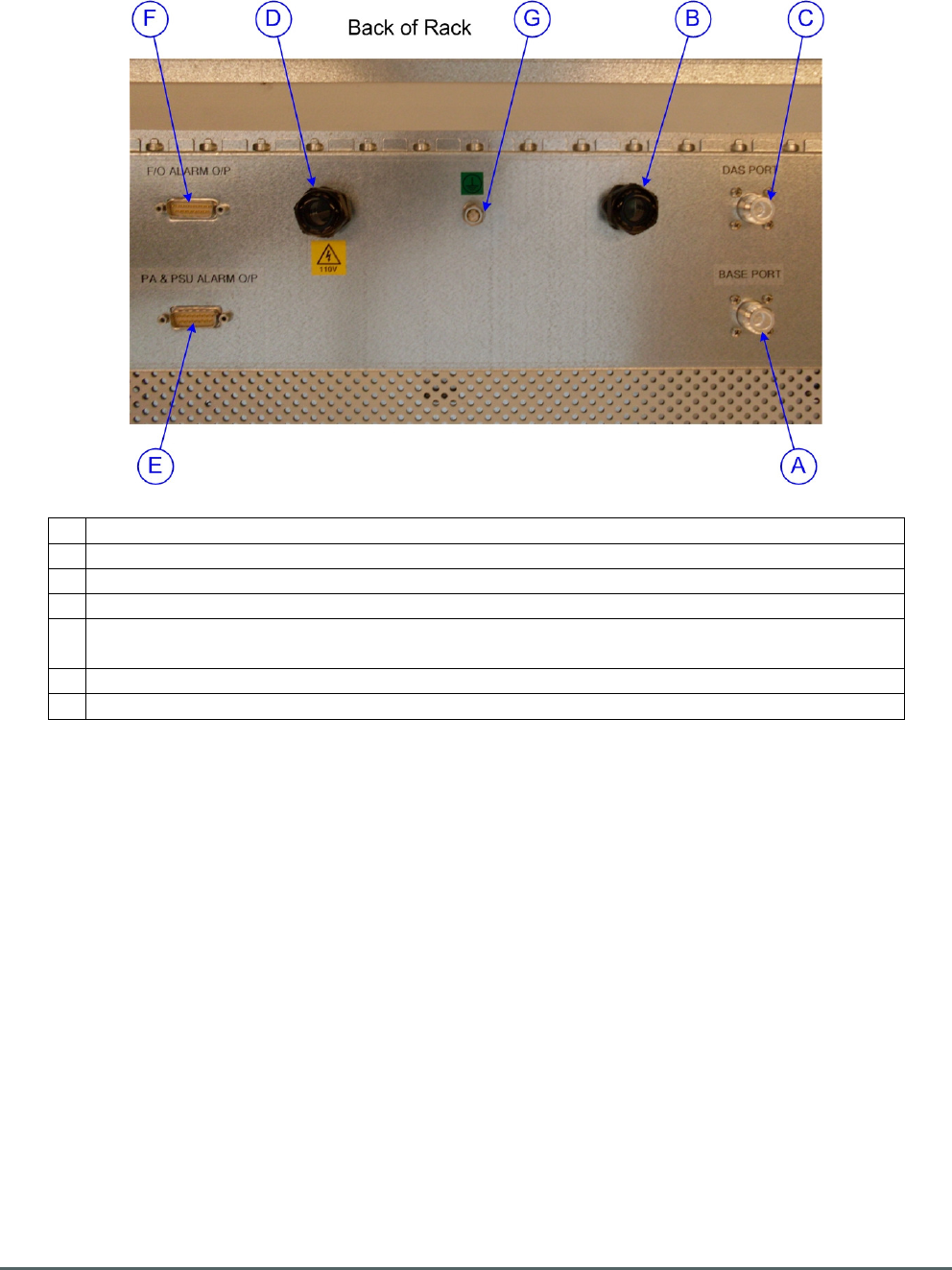
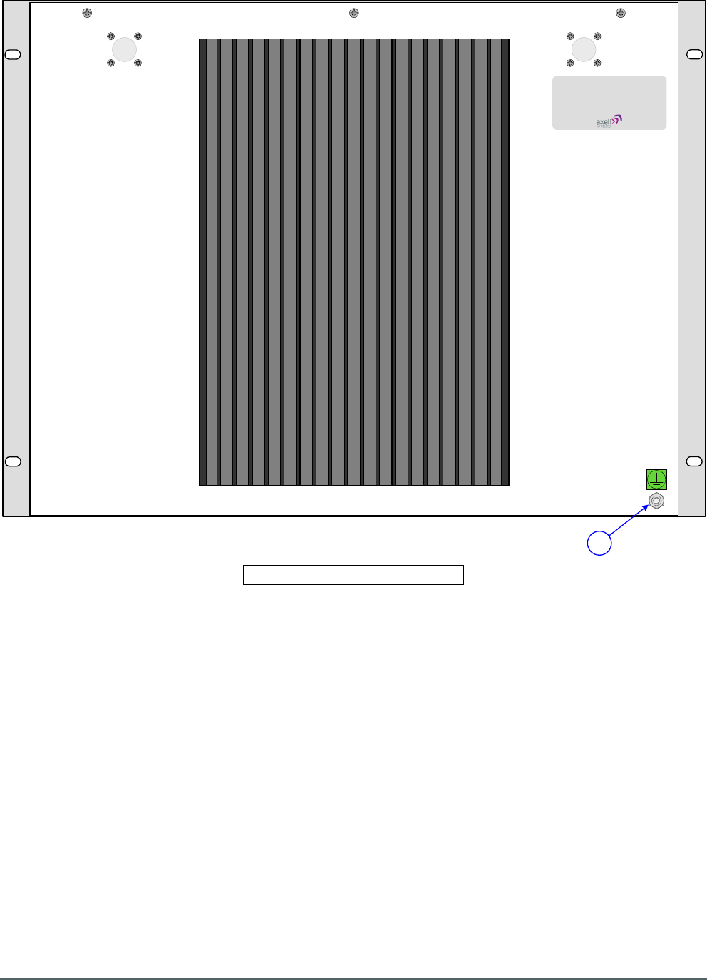
4.3.3. Ports on the Rack Lid
A N type port “BASE PORT”, D/L I/P from and U/L O/P to BTS
B Cable gland for optical fiber links to/from Gallery Place Station CRAS System
C N type port “DAS PORT”, D/L O/P to and U/L I/P from DAS
D Cable gland for AC mains wiring
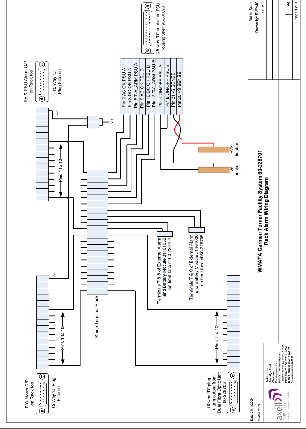
E 15 way “D” panel plug “PA & PSU ALARM O/P” alarm output from system amplifiers
and PSU modules
F 15 way “D” panel plug “F/O ALARM O/P” alarm output from fiber optic modules
G
Rack earthing connection
Axell Wireless Limited
Technical Literature
WMATA CRCS Redundant Antenna System
General Overview
Document Number 60-228701HBK Issue No. 3 Date 28/05/2010 Page 26 of 114
1
1
2
2
3
3
4
4
5
5
6
6
7
7
8
8
9
9
0
0
6
5
4
3
2
1
10
9
8
7
15
14
13
12
11
6
5
4
3
2
1
10
9
8
7
15
14
13
12
11
6
5
4
3
2
1
10
9
8
7
15
14
13
12
11
4.3.4. 60-228701 Alarm Wiring Schematic

Axell Wireless Limited
Technical Literature
WMATA CRCS Redundant Antenna System
General Overview
Document Number 60-228701HBK Issue No. 3 Date 28/05/2010 Page 27 of 114
4.4. Quadplexer (Base) 60-228706
Quadplexer (Base) 60-228706 is built into a 4U, 19” rack-mount case
Downlink RF from the BTS enters the rack via the N type connector labeled “BASE PORT” on the rack lid
(annotated “A” in section 4.3.3.) and the signal is fed to the N type port on the Quadplexer front panel
labeled “BASE” (annotated “A” in section 4.4.4.). The signal path passes through 30dB Directional Coupler
90-852330 which is used to provide a test/monitor port for the Uplink signal and then the signal path is split
into two branches, Band 1 and Band 2, by means of critical harness.
The Band 1 branch is then further split by critical harness into Uplink and Downlink paths and the Band 1
Downlink path passes through a Bandpass Filter 02-016801 which is tuned to pass the Band 1 Downlink
passband of 489.5MHz to 491.0MHz and to reject out-of-band signals and noise.
The Band 2 branch is also further split by critical harness into Uplink and Downlink paths and the Band 2
Downlink path passes through a Bandpass Filter 02-013401 which is tuned to pass the Band 2 Downlink
passband of 496.3MHz to 496.7MHz and to reject out-of-band signals and noise.
The two Downlink paths, Band 1 and Band 2 then exit the Quadplexer for their respective BDAs; the Band 1
Downlink exits the shelf for 8 Ch. Squelch Gated BDA 60-228704 via the N type port labeled “A” (annotated
“B” in section 4.4.4.) and the Band 2 Downlink exits the shelf for 8 Ch. Squelch Gated BDA 60-228705 via
the N type port labeled “C” (annotated “C” in section 4.4.4.)
The Band 1 Uplink from 8 Ch. Squelch Gated BDA 60-228704 enters the shelf via the N type port labeled
“B” (annotated “D” in section 4.4.4.) and passes through a Bandpass Filter 02-013401 which is tuned to
pass the Band 1 Uplink passband of 492.5MHz to 494.0MHz and to reject out-of-band signals and noise.
The Band 1 Uplink path is then combined with that of the Band 1 Downlink path by means of critical
harness.
The Band 2 Uplink from 8 Ch. Squelch Gated BDA 60-228705 enters the shelf via the N type port labeled
“D” (annotated “E” in section 4.4.4.) and passes through a Bandpass Filter 02-013401 which is tuned to
pass the Band 2 Uplink passband of 499.3MHz to 499.7MHz and to reject out-of-band signals and noise.
The Band 2 Uplink path is then combined with that of the Band 2 Downlink path by means of critical harness
and the Band 1 and Band 2 Uplink paths are then combined again by means of critical harness and the
combined Uplink path passes through the 30dB Directional Coupler 90-852330 which couples off a small
portion of the Uplink signal and feeds it to the N type port labeled “MONITORING” (annotated “F” in section
4.4.4.) providing a 30dB test/monitor port for the Uplink signal. The main Uplink signal then exits the shelf
via the N type port labeled “BASE” (annotated “A” in section 4.4.4.) and the signal is fed to the N type
connector labeled “BASE PORT” on the rack lid (annotated “A” in section 4.3.3.).

Axell Wireless Limited
Technical Literature
WMATA CRCS Redundant Antenna System
General Overview
Document Number 60-228701HBK Issue No. 3 Date 28/05/2010 Page 28 of 114
4.4.1. Quadplexer (Base) 60-228706 Major Sub-Components
Component
Part
Part Description Qty Per
Assembly
02-013401 Bandpass Filter 2
02-016801 Bandpass Filter 2
90-852330 30dB Directional Coupler 1
4.4.2. Quadplexer (Base) 60-228706 Specification
PARAMETER SPECIFICATION
Band 1 D/L (Base port to port A)
Frequency Range
489.5-491.0 MHz
Rejection
492.5-494.0 MHz > 65 dB
Insertion Loss
≤ 3.0 dB
Band 1 U/L (port B to Base port)
Frequency Range
492.5-494.0 MHz
Rejection
489.5-491.0 MHz > 40 dB
496.3-496.7 MHz > 65 dB
Insertion Loss
≤ 3.0 dB
Port B to Monitoring port
33dB ±1 dB
Band 2 D/L (Base port to port C)
Frequency Range
496.3-496.7 MHz
Rejection
492.5-494.0 MHz > 65 dB
499.3-499.7 MHz > 60 dB
Insertion Loss
≤ 3.0 dB
Band 2 U/L (port D to Base port)
Frequency Range
499.3-499.7 MHz
Rejection
496.3-496.7 MHz > 75 dB
Insertion Loss
≤ 3.0 dB
Port D to Monitoring port
33dB ±1 dB
Axell Wireless Limited
Technical Literature
WMATA CRCS Redundant Antenna System
General Overview
Document Number 60-228701HBK Issue No. 3 Date 28/05/2010 Page 29 of 114
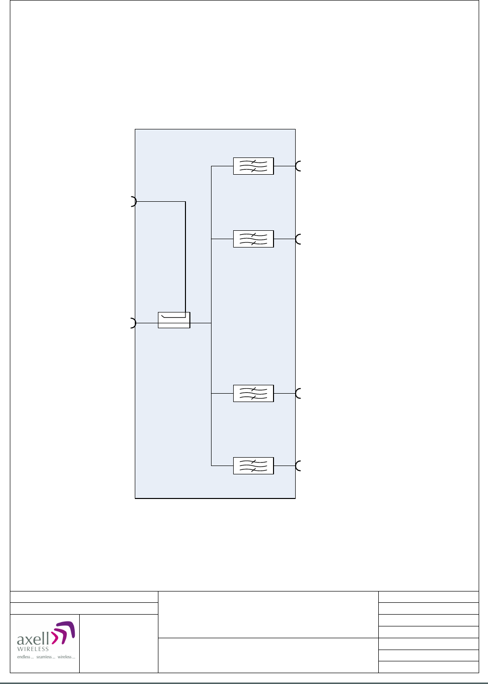
02-016801
489.5-491.0 MHz
90-852330
30 dB
Port A, Band 1 D/L O/P to
8 Ch. Squelch Gated BDA 60-228704
Date: 19/11/2009
© AWL 2009
Page 1 of 1
A4
Issue: 1
Drawn by: EW/AJS
Not to Scale
Aerial House
Asheridge Road
Chesham
Buckinghamshire
HP5 2QD United Kingdom
Telephone: +44 (0) 1494 777000
Facsimile: +44 (0) 1494 777002
E-Mail: info@axellwireless.com
www.axellwireless.com
Quadplexer (Base) 60-228706
System Diagram
02-016801
492.5-494.0 MHz
02-013401
496.3-496.7 MHz
02-013401
499.3-499.7 MHz
Port B, Band 1 U/L I/P from
8 Ch. Squelch Gated BDA 60-228704
Port D, Band 2 U/L I/P from
8 Ch. Squelch Gated BDA 60-228705
Port C, Band 2 D/L O/P to
8 Ch. Squelch Gated BDA 60-228705
Monitor Port
30dB coupled from U/L O/P
D/L I/P from BTS
U/L O/P to BTS
4.4.3. Quadplexer (Base) 60-228706 System Diagram
Axell Wireless Limited
Technical Literature
WMATA CRCS Redundant Antenna System
General Overview
Document Number 60-228701HBK Issue No. 3 Date 28/05/2010 Page 30 of 114
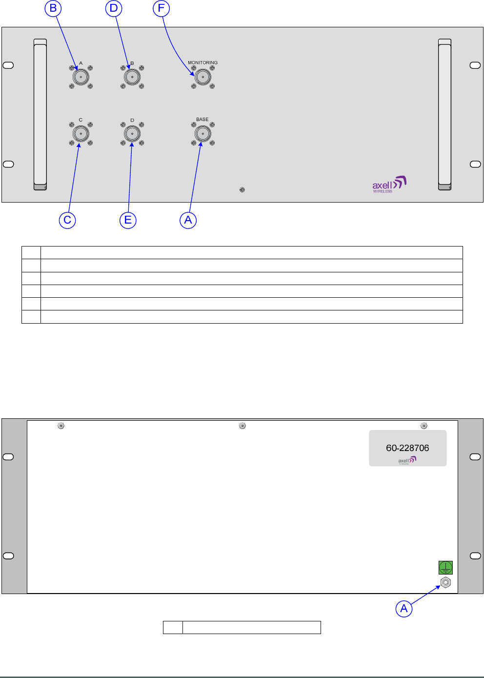
4.4.4. Quadplexer (Base) 60-228706 Front View
A N type port “BASE”, Downlink input from and Uplink output to BTS
B N type port “A”, Band 1 Downlink output to 8 Ch. Squelch Gated BDA 60-228704
C
N type port “C”, Band 2 Downlink output to 8 Ch. Squelch Gated BDA 60-228705
D
N type port “B”, Band 1 Uplink input from 8 Ch. Squelch Gated BDA 60-228704
E N type port “D”, Band 2 Uplink input from 8 Ch. Squelch Gated BDA 60-228705
F N type port “MONITORING”, 30dB test/monitor port coupled from the Uplink O/P path
4.4.5. Quadplexer (Base) 60-228706 Rear View
A Earthing connection

Axell Wireless Limited
Technical Literature
WMATA CRCS Redundant Antenna System
General Overview
Document Number 60-228701HBK Issue No. 3 Date 28/05/2010 Page 31 of 114
4.5. 8 Channel Squelch Gated BDA 60-228704
8 Ch. Squelch Gated BDA 60-228704 is built into an 8U, 19” rack-mount case
60-228704 utilizes Software Defined Radio (SDR) technology to digitally process the signal to define the
required channel frequencies and bandwidth (eight channels in the Downlink path and eight in the Uplink
path). As part of the digital signal processing function the signal amplitude is monitored to apply squelch
functionality to the signal path to attenuate unwanted noise when the input signal level is low. The unit is
pre-programmed with the 8 required duplex frequencies and channel bandwidths as indicated in section
4.5.2., these can be modified by the use of RMC software.
Band 1 Downlink RF from Quadplexer (Base) 60-228706 enters the BDA via the N type port labeled “A”
(annotated “A” in section 4.5.4.) and the Downlink signal passes through the Downlink path of UHF SDR
Module E931030 to define the 8 required Downlink channels.
After passing through the SDR module the Band 1 Downlink signal is split into two equal paths by 3dB
Splitter/Combiner 05-002603; The first path passes through the Downlink 25W Power Amplifier 12-026902
which provides 37dB of signal gain and then the signal exits the BDA via the N type port labeled “C”
(annotated “B” in section 4.5.4.) on its way to the local DAS by way of Quadplexer (DAS) 60-228706.
The second path from 3dB Splitter/Combiner 05-002603 exits the BDA for Splitter/Combiner Unit 60-228702
(and ultimately the Gallery Place Station CRAS System) via the N type port labeled “F” (annotated “C” in
section 4.5.4.)
Band 1 Uplink RF from the local DAS (by way of Quadplexer (DAS) 60-228706) enters the BDA via the N
type port labeled “D” (annotated “D” in section 4.5.4.) and passes through 15dB Directional Coupler 90-
852315 before entering UHF SDR Module E931030.
Band 1 Uplink RF from Splitter/Combiner Unit 60-228702 (from the Gallery Place Station CRAS System)
enters the BDA via the N type port labeled “E ” (annotated “E” in section 4.5.4.) and also passes
through15dB Directional Coupler 90-852315 where it is coupled onto the main Uplink signal path which
passes through the Uplink path of UHF SDR Module E931030 which utilizes SDR technology to digitally
process the signal to define the 8 required Uplink channels. After passing through the SDR module the
Band 1 Uplink signal passes through the Uplink 25W Power Amplifier 12-026902 which provides 37dB of
signal gain and then the signal exits the BDA via the N type port labeled “B” (annotated “F” in section 4.5.4.)
on its way to the BTS by way of Quadplexer (Base) 60-228706.
8 Ch. Squelch Gated BDA 60-228704 is powered by a 24V DC supply from the Redundant PSU Modules
96-300091 in PSU Housing Shelf 96-300090, The 24V DC supply powers the Power Amplifiers and an on-
board DC/DC converter J1421001 steps down the 24V supply to provide 6.45v and 15v DC to power the
SDR, Controller and Ext. Alarm/battery modules within the BDA.
Each Power Amplifiers have alarm outputs which are summed at the 9 way “D” panel plug labeled “ALARM”
on the front panel (annotated “J” in section 4.5.4.), the alarm data is connected to the External Alarm and
Battery Module J1161030 (annotated “K” in section 3.6.3.), from where the summary alarm data is fed to the
Krone terminal block located near the top of the rack (see section 4.3.2.).
The SDR controller module H561003 is used to control and supervise the SDR functionality, two ports are
provided where an operator may connect into the system, a local serial port, (a 9 way “D” panel socket
annotated “N” in section 4.6.4.) is used with a laptop PC running suitable terminal-emulation software to
interrogate and control the equipment using GET and SET commands. Alternatively the equipment can be
configured using RMC software via the RJ45 ethernet port (annotated “O” in section 4.6.4.) To ensure
synchronous communications between the SDR and the H56 controller, a high stability 10MHz reference
generator, R031002 is incorporated in the equipment backplane.

Axell Wireless Limited
Technical Literature
WMATA CRCS Redundant Antenna System
General Overview
Document Number 60-228701HBK Issue No. 3 Date 28/05/2010 Page 32 of 114
4.5.1. 8 Ch. Squelch Gated BDA 60-228704 List of Major Sub-Components
Component
Part
Part Description Qty Per
Assembly
05-002603 3dB Splitter/Combiner 1
12-026902 25W Power Amplifier 2
19-002202 Interconnection Assembly 1
90-852315 15dB Directional Coupler 1
96-110015 15A Fuse 1
E931030 UHF SDR Module (489.25MHz to 494.25MHz) 1
H561003 Control Module 1
J1161030 External Alarm and Battery Module 1
J1421001 DC/DC Converter 1
R031002 Reference Generator 1
4.5.2. 8 Ch. Squelch Gated BDA 60-228704 Specification
PARAMETER SPECIFICATION
Downlink
Frequency Range
489.5MHz to 491.0MHz
No of Channels
8
(1)
Maximum Gain
>+95 dB
Passband ripple
≤ ±1.5 dB
ALC Setting (all channels on)
+28 ±1 dBm
ALC Dynamic Range
>30 dB
Switched attenuator
0dB to 30 dB in 2dB steps ± 1dB
Noise Figure
≤ 4.5 dB (at maximum gain)
In Band Spurious Noise (30kHz B/W)
< -36 dBm (at maximum gain)
Squelch Level
-95dBm ±2 dBm
Uplink
Frequency Range
492.5MHz to 494.0MHz
No of Channels
8
(2)
Maximum Gain
>+95
Passband ripple
≤ ±1.5 dB
ALC Setting (all channels on)
+23 ±1 dBm
ALC Dynamic Range
>30 dB
Switched attenuator
0dB to 30 dB in 2dB steps ± 1dB
Noise Figure
≤ 4.5 dB (at maximum gain)
In Band Spurious Noise (30kHz B/W)
< -36 dBm (at maximum gain)
Squelch Level
-95 ±2 dBm
General
Supply Voltage
24V DC
Current consumption
< 12 A
Alarm output
Summary volts free dry contact output
(Closed = Normal / Open = Alarm)
pins 7 & 8 - Alarm connector
terminal on External Alarm and
Battery Module J1161030

Axell Wireless Limited
Technical Literature
WMATA CRCS Redundant Antenna System
General Overview
Document Number 60-228701HBK Issue No. 3 Date 28/05/2010 Page 33 of 114
(1)
Downlink Channels
Channel Number Channel Frequency Channel Bandwidth
14 489.5125 MHz 12.5 kHz
13 489.5375 MHz 12.5 kHz
2 490.7875 MHz 25.0 kHz
12 490.8375 MHz 12.5 kHz
1 490.8625 MHz 12.5 kHz
11 490.8875 MHz 12.5 kHz
10 490.9125 MHz 12.5 kHz
9 490.9625 MHz 25.0 kHz
(2)
Uplink Channels
Channel Number Channel Frequency Channel Bandwidth
14 492.5125 MHz 12.5 kHz
13 492.5375 MHz 12.5 kHz
2 493.7875 MHz 25.0 kHz
12 493.8375 MHz 12.5 kHz
1 493.8625 MHz 12.5 kHz
11 493.8875 MHz 12.5 kHz
10 493.9125 MHz 12.5 kHz
9 493.9625 MHz 25.0 kHz
Axell Wireless Limited
Technical Literature
WMATA CRCS Redundant Antenna System
General Overview
Document Number 60-228701HBK Issue No. 3 Date 28/05/2010 Page 34 of 114
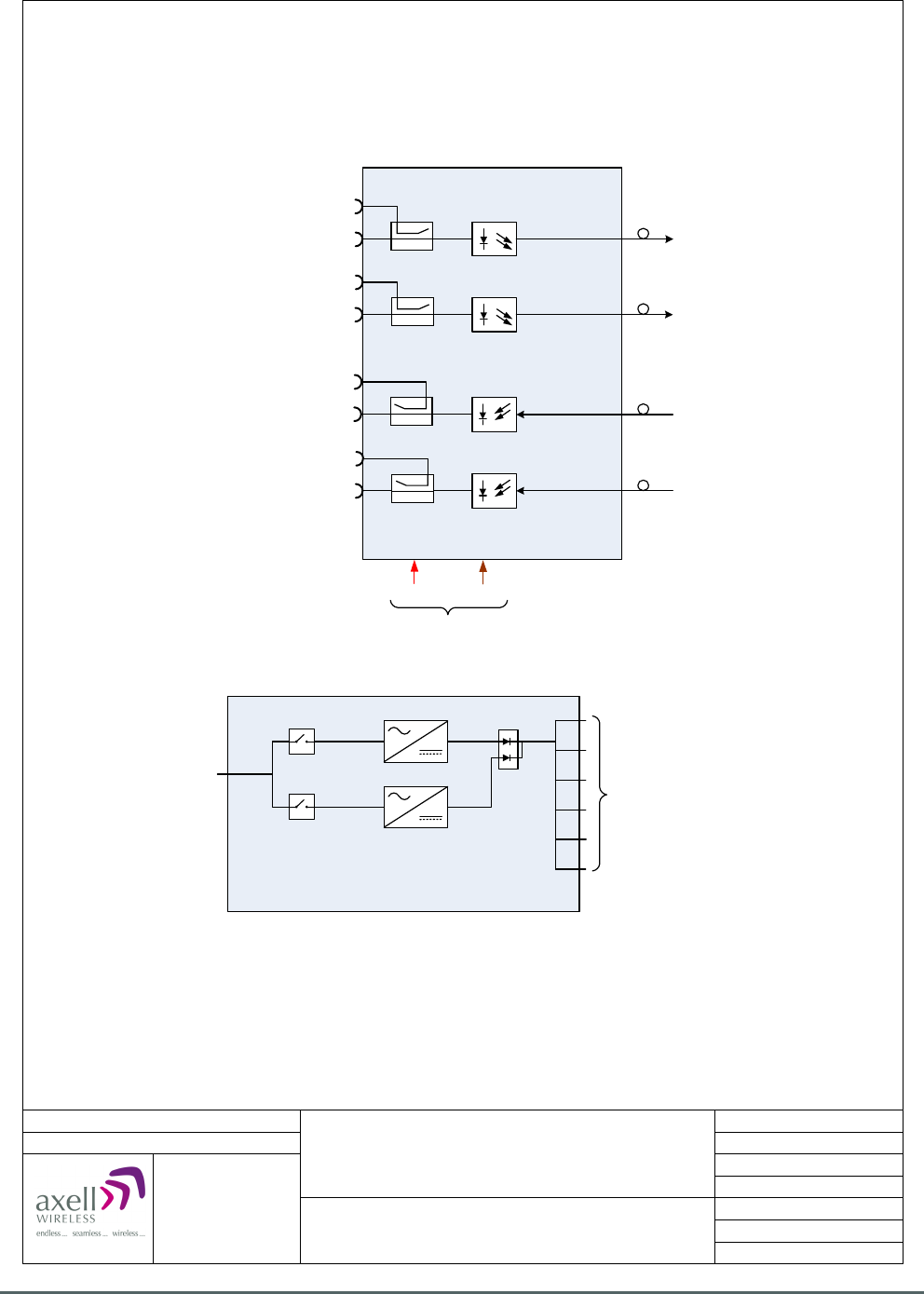
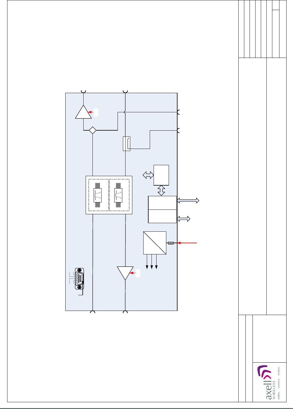
12-026902
25 W
24 V
4550 mA
Alarm
12-026902
25 W
24 V
4550 mA
05-002603
90-852315
15 dB
Port E, Band 1 U/L I/P from
Splitter/Combiner Unit 60-228702
Port F, Band 1 D/L O/P to
Splitter/Combiner Unit 60-228702
Port C, Band 1 D/L O/P
to Quadplexer (DAS) 60-228706
E931030
TETRA SDR MODULE
489.25-494.25 MHz
Controller
H561003
Alarm/Battery
J1161030
19-002202
1
0 V
Loop PA U/L Loop PA D/L
37dB
37dB
PC Control
System Monitoring Point
Port D, Band 1 U/L I/P
from Quadplexer (DAS) 60-228706
Port A, Band 1 D/L I/P from
Quadplexer (BASE) 60-228706
Port B, Band 1 U/L O/P to
Quadplexer (BASE) 60-228706
8 Ch. Squelch Gated BDA 60-228704
System Diagram
Date: 19/11/2009
Page 1 of 1
A4
Issue: 1
Drawn by: EW/AJS
Not to Scale
Aerial House
Asheridge Road
Chesham
Buckinghamshire
HP5 2QD United Kingdom
Telephone: +44 (0) 1494 777000
Facsimile: +44 (0) 1494 777002
E-Mail: info@axellwireless.com
www.axellwireless.com
© AWL 2009
9
+24 VDC
J142001
+15 VDC
+12 VDC
+6.45 VDC
96-110015
15A FUSE
8 CHANNEL
DSP D/L
8 CHANNEL
DSP U/L
4.5.3. 8 Ch. Squelch Gated BDA 60-228704 System Diagram
Axell Wireless Limited
Technical Literature
WMATA CRCS Redundant Antenna System
General Overview
Document Number 60-228701HBK Issue No. 3 Date 28/05/2010 Page 35 of 114
9
1
4.5.3.1 8 Ch. Squelch Gated BDA 60-228704 Alarm Wiring Diagram
Axell Wireless Limited
Technical Literature
WMATA CRCS Redundant Antenna System
General Overview
Document Number 60-228701HBK Issue No. 3 Date 28/05/2010 Page 36 of 114
LMT Port
Modem Status
Modem Power
Status
Login
4.5.4. 8 Ch. Squelch Gated BDA 60-228704 Front View
A N type port “A”, Band 1 D/L I/P from Quadplexer (Base) 60-228706
B N type port “C”, Band 1 D/L O/P to Quadplexer (DAS) 60-228706
C N type port “F”, Band 1 D/L O/P to Splitter/Combiner Unit 60-228702
(1)
D N type port “D”, Band 1 U/L I/P from Quadplexer (DAS) 60-228706
E N type port “E”, Band 1 U/L I/P from Splitter/Combiner Unit 60-228702
(2)
F N type port “B”, Band 1 U/L O/P to Quadplexer (Base) 60-228706
G
24V DC input from PSU module 96-300091 in PSU shelf 96-300090
H 15A fuse for DC input
I Green LED “POWER”, illuminated during normal operation
J 9 pin “D” panel plug “ALARM” local alarm output
K External Alarm and Battery Module J1161030
(3)
L Control Module H561003
(3)
M
Alarm to Krone Terminal Block on rack
N 9 pin “D” panel socket “LMT Port”, A local serial port enabling interrogation of alarm data by PC/laptop
O
RJ45 Ethernet socket enabling interrogation of alarm data by PC/laptop
(1)
Coupled from the D/L O/P to port “C”
(2)
Coupled to the U/L O/P to port “B”
(3)
For more information on the Control Module H561003 and External Alarm and Battery Module J1161030,
see document A1829300.
Axell Wireless Limited
Technical Literature
WMATA CRCS Redundant Antenna System
General Overview
Document Number 60-228701HBK Issue No. 3 Date 28/05/2010 Page 37 of 114
A
60-228704
4.5.5. 8 Ch. Squelch Gated BDA 60-228704 Rear View
A Earthing connection

Axell Wireless Limited
Technical Literature
WMATA CRCS Redundant Antenna System
General Overview
Document Number 60-228701HBK Issue No. 3 Date 28/05/2010 Page 38 of 114
4.6. 8 Ch. Squelch Gated BDA 60-228705
8 Ch. Squelch Gated BDA 60-228705 is built into an 8U, 19” rack-mount case.
60-228705 utilizes Software Defined Radio technology to digitally process the signal to define the required
channel frequencies and bandwidth (eight channels in the Downlink path and eight in the Uplink path). As
part of the digital signal processing function the signal amplitude is monitored to apply squelch functionality
to the signal path to attenuate unwanted noise when the input signal level is low. The unit is pre-
programmed with the 8 required duplex frequencies and channel bandwidths as indicated in section 4.6.2,
these can be modified by the use of RMC software.
Band 2 Downlink RF from Quadplexer (Base) 60-228706 enters the BDA via the N type port labeled “A”
(annotated “A” in section 4.6.4.) and the Downlink signal passes through the Downlink path of UHF SDR
Module E941030 to define the 8 required Downlink channels.
After passing through the SDR module the Band 2 Downlink signal is split into two equal paths by 3dB
Splitter/Combiner 05-002603; The first path passes through the Downlink 25W Power Amplifier 12-026902
which provides 37dB of signal gain and then the signal exits the BDA via the N type port labeled “C”
(annotated “B” in section 4.6.4.) on its way to the local DAS by way of Quadplexer (DAS) 60-228706.
The second path from 3dB Splitter/Combiner 05-002603 exits the BDA for Splitter/Combiner Unit 60-228702
(and ultimately the Gallery Place Station CRAS System) via the N type port labeled “F” (annotated “C” in
section 4.6.4.)
Band 2 Uplink RF from the local DAS (by way of Quadplexer (DAS) 60-228706) enters the BDA via the N
type port labeled “D” (annotated “D” in section 4.6.4.) and passes through 15dB Directional Coupler 90-
852315 before entering UHF SDR Module E941030.
Band 2 Uplink RF from Splitter/Combiner Unit 60-228702 (from the Gallery Place Station CRAS System)
enters the BDA via the N type port labeled “E ” (annotated “E” in section 4.6.4.) and also passes
through15dB Directional Coupler 90-852315 where it is coupled onto the main Uplink signal path which
passes through the Uplink path of UHF SDR Module E941030 which utilizes SDR technology to digitally
process the signal to define the 8 required Uplink channels. After passing through the SDR module the
Band 2 Uplink signal passes through the Uplink 25W Power Amplifier 12-026902 which provides 37dB of
signal gain and then the signal exits the BDA via the N type port labeled “B” (annotated “F” in section 4.6.4.)
on its way to the BTS by way of Quadplexer (Base) 60-228706.
8 Ch. Squelch Gated BDA 60-228705 is powered by a 24V DC supply from the Redundant PSU Modules
96-300091 in PSU Housing Shelf 96-300090, The 24V DC supply powers the Power Amplifiers and an on-
board DC/DC converter J1421001 steps down the 24V supply to provide 6.45v and 15v DC to power the
SDR, Controller and Ext. Alarm/battery modules within the BDA.
Each of the Power Amplifiers have alarm outputs which are summed at the 9 way “D” panel plug labeled
“ALARM” on the front panel (annotated “J” in section 4.6.4.), the alarm data is connected to the External
Alarm and Battery Module J1161030 (annotated “K” in section 4.6.4.), from where the summary alarm data
is fed to the Krone terminal block located near the top of the rack (see section 4.3.2.).
The SDR controller module H561003 is used to control and supervise the SDR functionality, two ports are
provided where an operator may connect into the system, a local serial port, (a 9 way “D” panel socket
annotated “N” in section 4.6.4.) is used with a laptop PC running suitable terminal-emulation software to
interrogate and control the equipment using GET and SET commands. Alternatively the equipment can be
configured using RMC software via the RJ45 ethernet port (annotated “O” in section 4.6.4.) To ensure
synchronous communications between the SDR and the H56 controller, a high stability 10MHz reference
generator, R031002 is incorporated in the equipment backplane.

Axell Wireless Limited
Technical Literature
WMATA CRCS Redundant Antenna System
General Overview
Document Number 60-228701HBK Issue No. 3 Date 28/05/2010 Page 39 of 114
4.6.1 8 Ch. Squelch Gated BDA 60-228705 List of Major Sub Components
Component
Part
Part Description Qty Per
Assembly
05-002603 3dB Splitter/Combiner 1
12-026902 25W Power Amplifier 2
19-002202 Interconnection Assembly 1
90-852315 15dB Directional Coupler 1
96-110015 15A Fuse 1
E941030 UHF SDR Module (495.5 - 500.5MHz) 1
H561003 Control Module 1
J1161030 External Alarm and Battery Module 1
J1421001 DC/DC Converter 1
R031002 Reference Generator 1
4.6.2. 8 Ch. Squelch Gated BDA 60-228705 Specification
PARAMETER SPECIFICATION
Downlink
Frequency Range
496.3MHz to 496.7MHz
No of Channels
8
(1)
Maximum Gain
>+95 dB
Passband ripple
≤ ±1.5 dB
ALC Setting (all channels on)
+28 ±1 dBm
ALC Dynamic Range
>30 dB
Switched attenuator
0dB to 30 dB in 2dB steps ± 1dB
Noise Figure
≤ 4.5 dB (at maximum gain)
In Band Spurious Noise (30kHz B/W)
< -36 dBm (at maximum gain)
Squelch Level
-95dBm ± 2 dBm
Uplink
Frequency Range
499.3MHz to 499.7MHz
No of Channels
8
(2)
Maximum Gain
>+95
Passband ripple
≤ ±1.5 dB
ALC Setting (all channels on)
+23 ±1 dBm
ALC Dynamic Range
>30 dB
Switched attenuator
0dB to 30 dB in 2dB steps ± 1dB
Noise Figure
≤ 4.5 dB (at maximum gain)
In Band Spurious Noise (30kHz B/W)
< -36 dBm (at maximum gain)
Squelch Level
-95 ± 2 dBm
General
Supply Voltage
24V DC
Current consumption
< 12 A
Alarm output
Summary volts free dry contact output
(Closed = Normal / Open = Alarm)
pins 7 & 8 - Alarm connector
terminal on External Alarm and
Battery Module J1161030

Axell Wireless Limited
Technical Literature
WMATA CRCS Redundant Antenna System
General Overview
Document Number 60-228701HBK Issue No. 3 Date 28/05/2010 Page 40 of 114
(1)
Downlink Channels
Channel Number Channel Frequency Channel Bandwidth
8 496.3375 MHz 25.0 kHz
3 496.4375 MHz 25.0 kHz
7 496.4875 MHz 12.5 kHz
Paging 496.5125 MHz 12.5 kHz
4 496.5375 MHz 12.5 kHz
6 496.5626 MHz 12.5 kHz
15 496.5875 MHz 12.5 kHz
5 496.6125 MHz 12.5 kHz
(2)
Uplink Channels
Channel Number Channel Frequency Channel Bandwidth
8 499.3375 MHz 25.0 kHz
3 499.4375 MHz 25.0 kHz
7 499.4875 MHz 12.5 kHz
Paging 499.5125 MHz 12.5 kHz
4 499.5375 MHz 12.5 kHz
6 499.5626 MHz 12.5 kHz
15 499.5875 MHz 12.5 kHz
5 499.6125 MHz 12.5 kHz
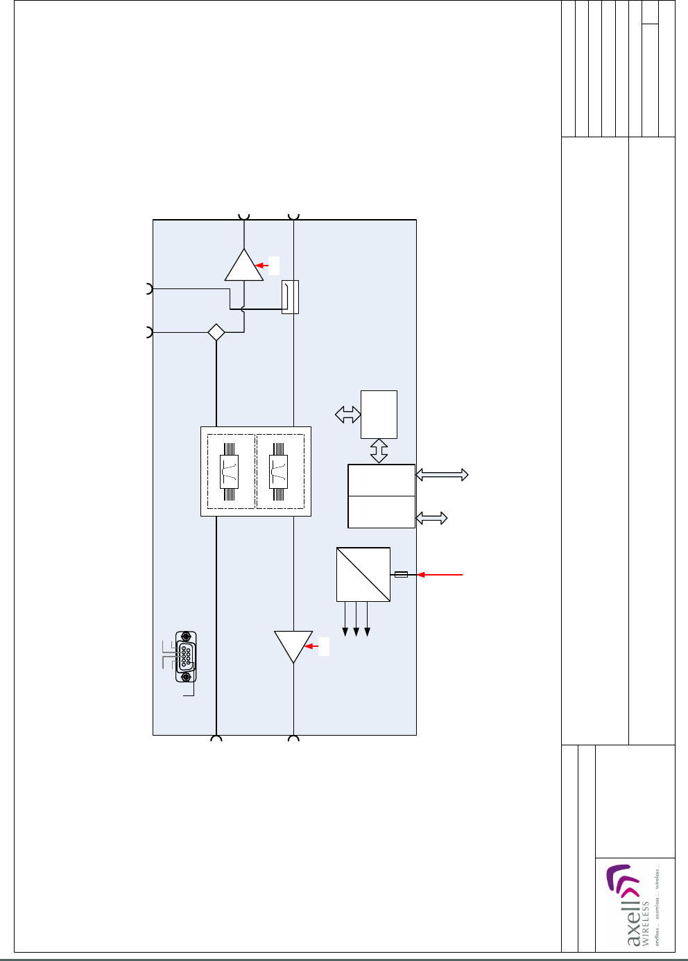
Axell Wireless Limited
Technical Literature
WMATA CRCS Redundant Antenna System
General Overview
Document Number 60-228701HBK Issue No. 3 Date 28/05/2010 Page 41 of 114
12-026902
25 W
24 V
4550 mA
Alarm
12-026902
25 W
24 V
4550 mA
05-002603
90-852315
15 dB
Port C, Band 2 D/L O/P
to Quadplexer (DAS) 60-228706
E941030
TETRA SDR MODULE
495.5 - 500.5 MHz
19-002202
37dB
37dB
PC Control
System Monitoring Point
Port D, Band 2 U/L I/P
from Quadplexer (DAS) 60-228706
Port A, Band 2 D/L I/P from
Quadplexer (BASE) 60-228706
Port B, Band 2 U/L O/P to
Quadplexer (BASE) 60-228706
8 Ch. Squelch Gated BDA 60-228705
System Diagram
Date: 19/11/2009
Page 1 of 1
A4
Issue: 1
Drawn by: EW/AJS
Not to Scale
Aerial House
Asheridge Road
Chesham
Buckinghamshire
HP5 2QD United Kingdom
Telephone: +44 (0) 1494 777000
Facsimile: +44 (0) 1494 777002
E-Mail: info@axellwireless.com
www.axellwireless.com
© AWL 2009
1
0 V
Loop PA U/L Loop PA D/L
9
Port E, Band 2 U/L I/P from
Splitter/Combiner Unit 60-228702
Port F, Band 2 D/L O/P to
Splitter/Combiner Unit 60-228702
Controller
H561003
Alarm/Battery
J1161030
+24 VDC
J142001
+15 VDC
+12 VDC
+6.45 VDC
96-110015
15A FUSE
8 CHANNEL
DSP D/L
8 CHANNEL
DSP U/L
4.6.3. 8 Ch. Squelch Gated BDA 60-228705 System Diagram
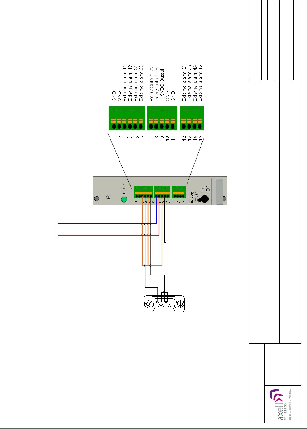
Axell Wireless Limited
Technical Literature
WMATA CRCS Redundant Antenna System
General Overview
Document Number 60-228701HBK Issue No. 3 Date 28/05/2010 Page 42 of 114
9
1
+15 V Orange
GND
9 way “D” plug, alarm
output on
8 Ch. Squelch Gated
BDA 60-228705
Red Blue
Alarm Dry Contact Output to
Krone terminal block,
terminals 7 & 7 for 60-228705
Date: 30/11/2009
© AWL 2009
Page 1 of 1
A4
Issue: 1
Drawn by: EW/AJS
Not to Scale
8 Ch. Squelch Gated BDA 60-228705
Alarm Wiring Diagram
Aerial House
Asheridge Road
Chesham
Buckinghamshire
HP5 2QD United Kingdom
Telephone: +44 (0) 1494 777000
Facsimile: +44 (0) 1494 777002
E-Mail: info@axellwireless.com
www.axellwireless.com
4.6.3.1. 8 Ch. Squelch Gated BDA 60-228705 Alarm Wiring Diagram
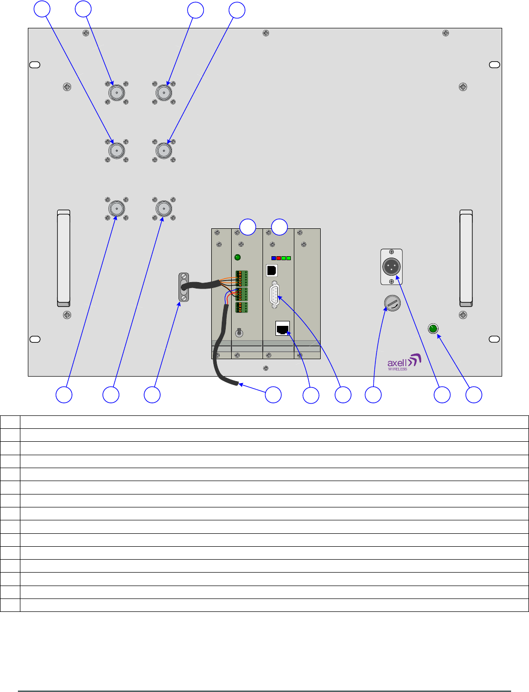
Axell Wireless Limited
Technical Literature
WMATA CRCS Redundant Antenna System
General Overview
Document Number 60-228701HBK Issue No. 3 Date 28/05/2010 Page 43 of 114
AB
CD
E F
+24V DC
T15A
POWER
12
13
14
15
7
8
9
10
11
1
2
3
4
5
6
PWR
Battery
Power
ON
OFF Ethernet 10 /100
LMT Port
Modem Status
Modem Power
Status
Login
ALARM
AB D
E C J IH G
F
K
N
L
MO
4.6.4. 8 Ch. Squelch Gated BDA 60-228705 Front View
A N type port “A”, Band 2 D/L I/P from Quadplexer (Base) 60-228706
B N type port “C”, Band 2 D/L O/P to Quadplexer (DAS) 60-228706
C N type port “F”, Band 2 D/L O/P to Splitter/Combiner Unit 60-228702
(1)
D N type port “D”, Band 2 U/L I/P from Quadplexer (DAS) 60-228706
E N type port “E”, Band 2 U/L I/P from Splitter/Combiner Unit 60-228702
(2)
F N type port “B”, Band 2 U/L O/P to Quadplexer (Base) 60-228706
G
24V DC input from PSU module 96-300091 in PSU shelf 96-300090
H 15A fuse for DC input
I Green LED “POWER”, illuminated during normal operation
J 9 pin “D” panel plug “ALARM” local alarm output
K External Alarm and Battery Module J1161030
(3)
L Control Module H561003
(3)
M
Alarm to Krone Terminal Block on rack
N 9 pin “D” panel socket “LMT Port”, A local serial port enabling interrogation of alarm data by PC/laptop
O
RJ45 Ethernet socket enabling interrogation of alarm data by PC/laptop
(1)
Coupled from D/L O/P to port “C”
(2)
Coupled to U/L O/P to port “B”
(3)
For more information on the Control Module H561003 and External Alarm and Battery Module J1161030,
see document A1829300.
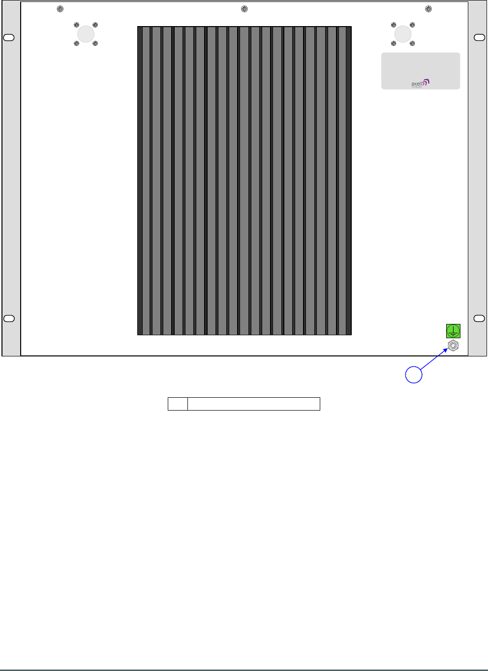
Axell Wireless Limited
Technical Literature
WMATA CRCS Redundant Antenna System
General Overview
Document Number 60-228701HBK Issue No. 3 Date 28/05/2010 Page 44 of 114
A
60-228705
4.6.5. 8 Ch. Squelch Gated BDA 60-228705 Rear View
A Earthing connection

Axell Wireless Limited
Technical Literature
WMATA CRCS Redundant Antenna System
General Overview
Document Number 60-228701HBK Issue No. 3 Date 28/05/2010 Page 45 of 114
4.7. Splitter/Combiner Unit 60-228702
Splitter/Combiner Unit 60-228702 is built into a 2U, 19” rack-mount case.
Band 1 Downlink RF from 8 Ch. Squelch Gated BDA 60-228704 enters the Splitter/Combiner Unit via the N
type port labeled “A” (annotated “A” in section 4.7.4.) and passes into the Downlink 3dB Splitter/Combiner
05-002603.
Band 2 Downlink RF from 8 Ch. Squelch Gated BDA 60-228705 enters the Splitter/Combiner Unit via the N
type port labeled “B” (annotated “B” in section 4.7.4.) and also passes into the Downlink 3dB
Splitter/Combiner 05-002603 which combines the two Downlink paths and the combined path then passes
through the Downlink Variable Switched Attenuator 10-000901 (annotated “A” in section 4.7.5.) which can
provide up to 15dB of signal gain (in 1dB steps) if required; the attenuation value is controlled by the four
toggle switches on the attenuator body; each switch is clearly marked with the attenuation it provides, and
the total attenuation in-line is the sum of the values switched in.
After passing through the Downlink attenuator the Downlink signal exits the Splitter/Combiner for Dual Fiber
Optic Unit 60-228703 via the N type port labeled “TX” (annotated “C” in section 4.7.4.).
Uplink RF from Dual Fiber Optic Unit 60-228703 enters the Splitter/Combiner via the N type port labeled
“RX” (annotated “D” in section 4.7.4.) and the Uplink signal passes through the Uplink Variable Switched
Attenuator 10-000701 (annotated “B” in section 4.7.5.) which can provide up to 30dB of signal gain (in 2dB
steps) if required; the attenuation value is controlled by the four toggle switches on the attenuator body;
each switch is clearly marked with the attenuation it provides, and the total attenuation in-line is the sum of
the values switched in.
After passing through the Uplink attenuator the signal path passes into the Uplink 3dB Splitter/Combiner 05-
002603 which splits the signal into two equal paths, One path (Band 1) exits Splitter/Combiner Unit 60-
228702 for 8 Ch. Squelch Gated BDA 60-228704 via the N type port labeled “C” (annotated “E” in section
4.7.4.) and the second path (Band 2) exits Splitter/Combiner Unit 60-228702 for 8 Ch. Squelch Gated BDA
60-228705 via the N type port labeled “D” (annotated “F” in section 4.7.4.).
4.7.1. Splitter/Combiner Unit 60-228702 List of Major Sub-Components
Component
Part
Part Description Qty Per
Assembly
05-002603 3dB Splitter/Combiner 2
10-000701 Variable Switched Attenuator 0-30dB 1
10-000901 Variable Switched Attenuator 0-15dB 1
4.7.2. Splitter/Combiner Unit 60-228702 Specification
PARAMETER SPECIFICATION
Downlink
Frequency range
Band 1, 489.5MHz to 491.0MHz
Band 2, 496.3MHz to 496.7MHz
Switched attenuator
0dB to 15 dB in 1dB steps
Uplink
Frequency range
Band 1, 492.5MHz to 494.0MHz
Band 2, 499.3MHz to 499.7MHz
Switched attenuator
0dB to 30 dB in 2 dB steps
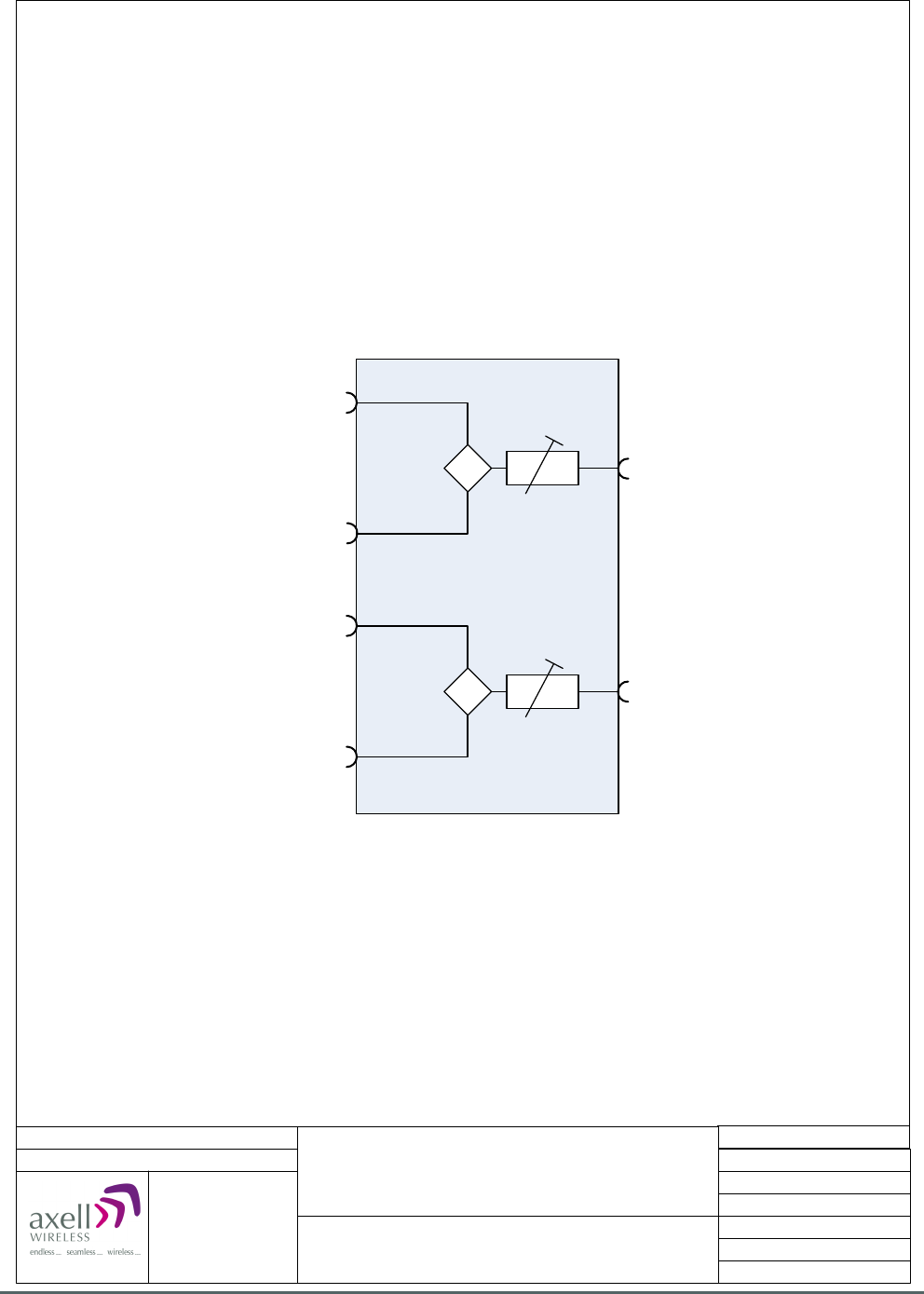
Axell Wireless Limited
Technical Literature
WMATA CRCS Redundant Antenna System
General Overview
Document Number 60-228701HBK Issue No. 3 Date 28/05/2010 Page 46 of 114
Port A, Band 1 D/L I/P from
8 Ch. Squelch Gated BDA 60-228704
Port TX, D/L O/P to
Dual Fibre Optic Unit 60-228703
10-000901
0-15 dB
05-002603
10-000701
0-30 dB
Date: 26/11/2009
© AWL 2009
Page 1 of 1
A4
Issue: 1
Drawn by: EW/AJS
Not to Scale
Aerial House
Asheridge Road
Chesham
Buckinghamshire
HP5 2QD United Kingdom
Telephone: +44 (0) 1494 777000
Facsimile: +44 (0) 1494 777002
E-Mail: info@axellwireless.com
www.axellwireless.com
Splitter/Combiner Unit 60-228702
System Diagram
Port A, Band 2 D/L I/P from
8 Ch. Squelch Gated BDA 60-228705
Port RX, U/L I/P from
Dual Fibre Optic Unit 60-228703
05-002603
Port C, Band 1 U/L O/P to
8 Ch. Squelch Gated BDA 60-228704
Port D, Band 2 U/L O/P to
8 Ch. Squelch Gated BDA 60-228705
4.7.3. Splitter/Combiner Unit 60-228702 System Diagram
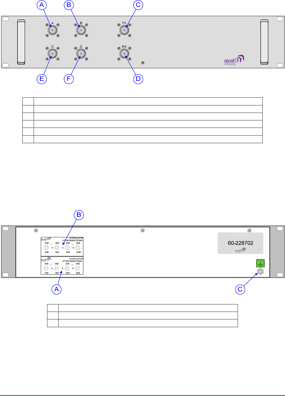
Axell Wireless Limited
Technical Literature
WMATA CRCS Redundant Antenna System
General Overview
Document Number 60-228701HBK Issue No. 3 Date 28/05/2010 Page 47 of 114
4.7.4. Splitter/Combiner Unit 60-228702 Front View
A N type port “A”, D/L I/P from 8 Ch. Squelch Gated BDA 60-228704
B N type port “B”, D/L I/P from 8 Ch. Squelch Gated BDA 60-228705
C
N type port “TX” D/L O/P to Dual Fiber Optic Unit 60-228703
D
N type port “RX” U/L I/P from Dual Fiber Optic Unit 60-228703
E N type port “C”, U/L O/P to 8 Ch. Squelch Gated BDA 60-228704
F N type port “D”, U/L O/P to 8 Ch. Squelch Gated BDA 60-228705
4.7.5. Splitter/Combiner Unit 60-228702 Rear View
A Downlink Variable Switched Attenuator 10-000901 (0-15dB)
B Uplink Variable Switched Attenuator 10-000701 (0-30dB)
C
Earthing connection

Axell Wireless Limited
Technical Literature
WMATA CRCS Redundant Antenna System
General Overview
Document Number 60-228701HBK Issue No. 3 Date 28/05/2010 Page 48 of 114
4.8. Dual Fiber Optic Unit 60-228703
Dual Fiber Optic Unit 60-228703 is built into a 2U, 19” rack-mount case.
Downlink RF from Splitter/Combiner Unit 60-228702 enters the Dual Fiber Optic Unit via the N type port
labeled “TX 1” (annotated “A” in section 4.8.4.) and passes through a 20dB Directional Coupler 90-852420
which couples off a small portion of the signal and feeds it to the N type port labeled “MON -20dB TX 1”
(annotated “B” in section 4.8.4.) which provides a 20dB test/monitor port for the Downlink input.
The main Downlink path then passes into a Fiber Optic Transmitter Module 20-005401 where the RF signal
is modulated onto a laser and the optical signal thus produced then exits the Dual Fiber Optic Unit via the
SC/APC optical port 1 “TX” (annotated “C” in section 4.8.4.) and is transmitted to the Gallery Place Station
CRAS System via a fiber optic cable link, this is the Main Redundant optical Downlink signal.
The N type port labeled “TX 2” (annotated “D” in section 4.8.4.) is a Downlink input to a separate, parallel,
Standby Redundant Downlink path with its own Directional Coupler, test monitor port (annotated “E” in
section 4.8.4.) and Fiber Optic Transmitter Module. The Optical output from the Standby Redundant
Downlink path exits the Dual Fiber Optic Unit via the SC/APC optical port 2 “TX” (annotated “F” in section
4.8.4.) Switching between the Main Redundant and Standby Redundant Downlink paths is accomplished
manually by disconnecting the Downlink RF input from the “TX 1” port and connecting it to the “TX 2” port,
and by disconnecting the optical Downlink output cable from the SC/APC optical port 1 “TX” and connecting
it to the SC/APC optical port 2 “TX”. N.B. The safety precautions noted in section 2 must be observed when
changing from Main to Standby Redundant.
The Main Redundant Uplink optical signal from the Gallery Place Station CRAS System enters the Dual
Fiber Optic Unit via the SC/APC optical port 1 “RX” (annotated “G” in section 4.8.4.) and passes into a Fiber
Optic Receiver Module 20-005501 which demodulates the Uplink signal to RF and the Uplink RF signal then
passes through a 20dB Directional Coupler 90-852420 which couples off a small portion of the signal and
feeds it to the N type port labeled “MON -20dB RX 1” (annotated “I” in section 4.8.4.) which provides a 20dB
test/monitor port for the Main Redundant Uplink output. The Main Redundant Uplink path then exits the Dual
Fiber Optic Unit for Splitter/Combiner Unit 60-228702 via the N type port labeled “RX 1” (annotated “H” in
section 4.8.4.)
The SC/APC optical port 2 “RX” (annotated “J” in section 4.8.4.) is an Uplink input to a separate, parallel,
Standby Redundant Uplink path with its own Fiber Optic Receiver Module, Directional Coupler and
test/monitor port (annotated “L” in section 4.8.4.) The RF output from the Standby Redundant Uplink path
exits the Dual Fiber Optic Unit for Splitter/Combiner Unit 60-228702 via the N type port labeled “RX 2”
(annotated “K” in section 4.8.4.)
Switching between the Main Redundant and Standby Redundant Uplink paths is accomplished manually by
disconnecting the optical Uplink input cable from the SC/APC optical port 1 “RX” and connecting it to the
SC/APC optical port 2 “RX”, and by disconnecting the Uplink RF output from the “RX 1” port and connecting
it to the “RX 2” port. N.B. The safety precautions noted in section 2 must be observed when changing from
Main to Standby Redundant.
Dual Fiber Optic Unit 60-228703 is powered by a 24V DC supply from one of the PSU Modules 96-300091
in PSU Housing Shelf 96-300090, The 24V DC supply powers two on-board DC/DC converters 96-200024
arranged in a parallel dual redundant configuration, the outputs of which are combined by power diodes to
provide a 12V DC supply for the fiber optic modules within the unit
An alarm system is fitted to Dual Fiber Optic Unit 60-228703, each of the fiber optic modules carries its own
voltage-free contact alarm relay output which are summed at the 15 way “D” panel plug labeled “ALARM”
(annotated “EE” in section 4.8.4.) which connects to the Krone terminal block located near the top of the
rack (see section 4.3.2.).

Axell Wireless Limited
Technical Literature
WMATA CRCS Redundant Antenna System
General Overview
Document Number 60-228701HBK Issue No. 3 Date 28/05/2010 Page 49 of 114
4.8.1. Dual Fiber Optic Unit 60-228703 List of Major Sub-Components
Component
Part
Part Description Qty Per
Assembly
20-001601 12V Dual Relay Board 1
20-005401 Fiber Optic Transmitter Module 2
20-005501 Fiber Optic Receiver Module 2
96-110013 3.15 A Fuse 2
96-200024 DC/DC Converter 2
90-852420 20dB Directional Coupler 4
94-100003 Power Diode 3
4.8.2. Dual Fiber Optic Unit 60-228703 Specification
PARAMETER SPECIFICATION
RF Downlink
Frequency range
489.5MHz to 491.0MHz
496.3MHz to 496.7MHz
Coupling TX1 to Mon TX1
20 dB±1
Coupling TX2 to Mon TX2
20 dB±1
Optical Downlink
Wavelength
1310nm
TX(A) Optical TX Power
1-3 dBm
TX(B) Optical TX Power
1-3 dBm
Optical Uplink
Wavelength
1550nm
RX(A) Gain
>+15 dB
RX(A) Gain Set To
0 dB±0.5
RX(A) Alarm Threshold
< -10dBm
RX(B) Gain
>+15 dB
RX(A) Gain Set To
0 dB±0.5
RX(B) Alarm Threshold
< -10dBm
RF Uplink
Frequency range
499.3MHz to 499.7MHz
492.5MHz to 494.0MHz
Coupling RX1 to Mon RX1
20 dB±1
Coupling RX2 to Mon RX2
20 dB±1
General
Supply Voltage
12V DC or 24V DC
Current consumption
< 1.0A @ 24V DC input
< 1.5A @ 12V DC input
Alarm output
Summary volts free dry contact output
(Closed = Normal / Open = Alarm)
F/O TX1 contact output Pin 1 & 2
F/O TX2 contact output Pin 3 & 4
F/O RX1 contact output Pin 5 & 6
F/O RX1 contact output Pin 7 & 8
24V DC-DC contact output Pin 9 & 10**
**This alarm is not operational when the unit is powered from 12V DC
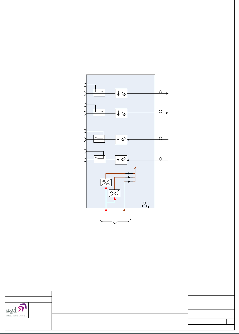
Axell Wireless Limited
Technical Literature
WMATA CRCS Redundant Antenna System
General Overview
Document Number 60-228701HBK Issue No. 3 Date 28/05/2010 Page 50 of 114
Dual Fibre Optic Unit 60-228703
System Diagram
(Carmen Turner Facility System)
20-005401
20-005501
Port TX1 Main Redundant D/L I/P from
Splitter/Combiner Unit 60-228702
20-001601
Local Alarm
TX1 Monitor
Port TX2 Standby Redundant D/L I/P from
Splitter/Combiner Unit 60-228702
TX2 Monitor
Port RX1 Main Redundant U/L O/P to
Splitter/Combiner Unit 60-228702
RX1 Monitor
RX2 Monitor
Port RX2 Standby Redundant U/L O/P to
Splitter/Combiner Unit 60-228702
20-005401
20-005501
90-852420
90-852420
90-852420
90-852420
+24 VDC
2 x
96-200024
+12 VDC
3 x
94-100003
Date: 8/12/2009
Aerial House
Asheridge Road
Chesham
Buckinghamshire
HP5 2QD
United Kingdom
© AWL 2009
Optical Port 1 “TX”
Main Redundant D/L O/P to
Gallery Place Station system
Optical Port 1 “RX”
Main Redundant U/L I/P from
Gallery Place Station system
Optical Port 2 “TX”
Standby Redundant D/L O/P to
Gallery Place Station system
Optical Port 2 “RX”
Standby Redundant U/L I/P from
Gallery Place Station system
DC I/P
Page 1 of 1
A4
Issue: 2
Drawn by: EW/AJS
Not to Scale
Telephone: +44 (0) 1494 777000
Facsimile: +44 (0) 1494 777002
E-Mail: info@axellwireless.com
www.axellwireless.com
4.8.3. Dual Fiber Optic Unit 60-228703 System Diagram
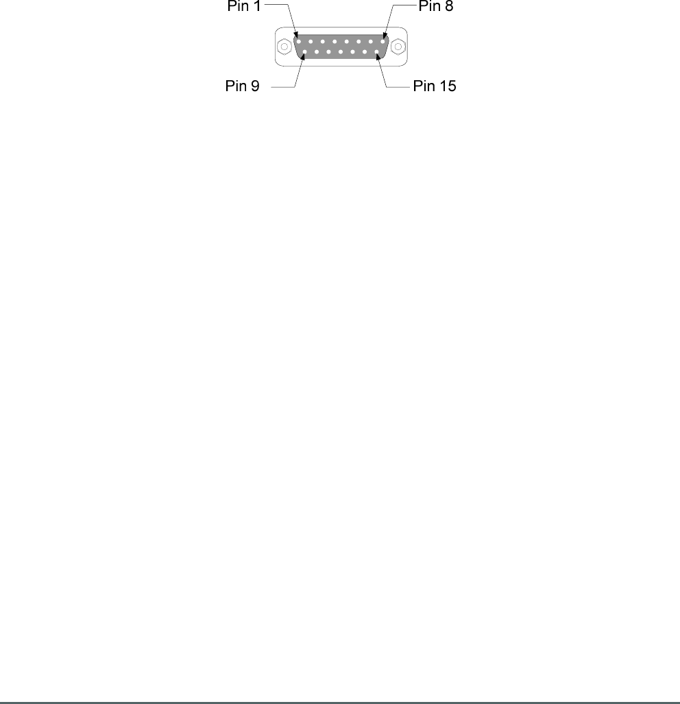
Axell Wireless Limited
Technical Literature
WMATA CRCS Redundant Antenna System
General Overview
Document Number 60-228701HBK Issue No. 3 Date 28/05/2010 Page 51 of 114
4.8.3.1. Dual Fiber Optic Unit 60-228703 Alarm Outputs
15 pin “D” panel plug “ALARM”, local alarm output to Krone terminal block on rack (annotated “EE” in
section 3.8.4.)
Dry Contact Outputs (Closed = Normal / Open = Alarm)
F/O TX1 contact output Pin 1 & 2
F/O TX2 contact output Pin 3 & 4
F/O RX1 contact output Pin 5 & 6
F/O RX1 contact output Pin 7 & 8
24V DC>DC contact output Pin 9 & 10
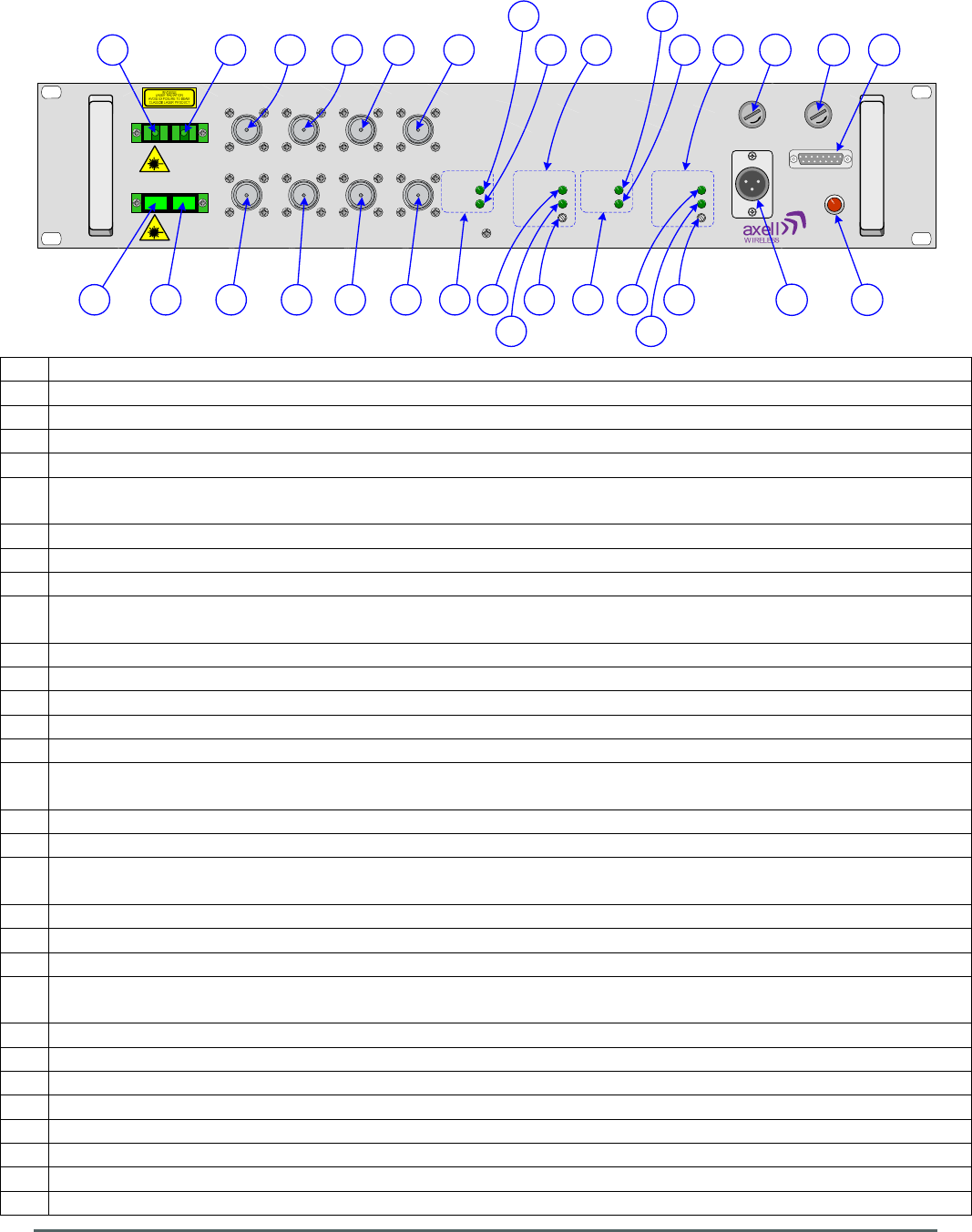
Axell Wireless Limited
Technical Literature
WMATA CRCS Redundant Antenna System
General Overview
Document Number 60-228701HBK Issue No. 3 Date 28/05/2010 Page 52 of 114
TX RX
TX RX
1
2
POWER
ALARM
GAIN ADJ
POWER
ALARM
POWER
ALARM
POWER
ALARM
GAIN ADJ
MON
-20dB TX 1
MON
-20dB RX 1
MON
-20dB RX 2
MON
-20dB TX 2
TX 1 RX 1
TX 2 RX 2 TX 1 RX 1 TX 2 RX 2
DC/DC FAIL
ALARM
24V T3.15A12V T3.15A
+24/12V DC
B
D
C A
EF
G HI
L KJ M
O
N
P
R
Q
W
Y
X Z
U
T V
S
AA
BBCC
DD
EE
4.8.4. Dual Fiber Optic Unit 60-228703 Front View
A N type port “TX1”, Main Redundant D/L I/P from Splitter/Combiner Unit 60-228702
B N type port “MON -20dB TX 1”, 20dB test/monitor port coupled from D/L input to port “TX1”
C SC/APC optical port 1 “TX”, Main Redundant optical D/L O/P to Gallery Place Station CRAS System
D N type port “TX2”, Standby Redundant D/L I/P from Splitter/Combiner Unit 60-228702
E N type port “MON -20dB TX 2”, 20dB test/monitor port coupled from standby D/L input to port “TX2”
F SC/APC optical port 2 “TX”, Standby Redundant optical D/L O/P to Gallery Place Station CRAS
System
G SC/APC optical port 1 “RX”, Main Redundant optical U/L I/P from Gallery Place Station CRAS System
H N type port “RX1”, Main Redundant U/L O/P to Splitter/Combiner Unit 60-228702
I N type port “MON -20dB RX 1”, 20dB test/monitor port coupled from U/L output to port “RX1”
J SC/APC optical port 2 “RX”, Standby Redundant optical U/L I/P from Gallery Place Station CRAS
System
K N type port “RX2”, Standby Redundant U/L O/P to Splitter/Combiner Unit 60-228702
L N type port “MON -20dB RX 2”, 20dB test/monitor port coupled from standby U/L output to port “RX2”
M Status Indicators for F/O TX Module 1 (Main Redundant D/L to Gallery Place Station CRAS System)
N Green LED “POWER”, Fiber Optic TX Power On indicator illuminated during normal operation
O Green LED “ALARM”, Fiber Optic TX Alarm indicator extinguished during alarm state
P Status Indicators for F/O TX Module 2 (Standby Redundant D/L to Gallery Place Station CRAS
System)
Q Green LED “POWER”, Fiber Optic TX Power On indicator illuminated during normal operation
R Green LED “ALARM”, Fiber Optic TX Alarm indicator extinguished during alarm state
S Status Indicators for F/O RX Module 1 (Main Redundant U/L from Gallery Place Station CRAS
System)
T Green LED “POWER”, Fiber Optic RX Power On indicator illuminated during normal operation
U Green LED “ALARM”, Fiber Optic RX Alarm indicator extinguished during alarm state
V Fiber Optic RX RF gain adjustment
W Status Indicators for F/O RX Module 2 (Standby Redundant U/L from Gallery Place Station CRAS
System)
X Green LED “POWER”, Fiber Optic RX Power On indicator illuminated during normal operation
Y Green LED “ALARM”, Fiber Optic RX Alarm indicator extinguished during alarm state
Z Fiber Optic RX RF gain adjustment
AA DC input (12V or 24V)
BB 3.15A Fuse for 24V DC input
CC
3.15A Fuse for 12V DC input
DD
Red LED “DC/DC FAIL” illuminated in alarm state (DC/DC convertor failure)
EE 15 pin “D” panel plug “ALARM” local alarm output to Krone terminal block on rack

Axell Wireless Limited
Technical Literature
WMATA CRCS Redundant Antenna System
General Overview
Document Number 60-228701HBK Issue No. 3 Date 28/05/2010 Page 53 of 114
4.8.5. Dual Fiber Optic Unit 60-228703 Rear View
A Earthing connection

Axell Wireless Limited
Technical Literature
WMATA CRCS Redundant Antenna System
General Overview
Document Number 60-228701HBK Issue No. 3 Date 28/05/2010 Page 54 of 114
4.9. Quadplexer (DAS) 60-228706
Quadplexer (DAS) 60-228706 is built into a 4U, 19” rack-mount case
Band 1 Downlink RF from the 8 Ch. Squelch Gated BDA 60-228704 enters the shelf via the N type port
labeled “A” (annotated “A” in section 4.9.4.) and passes through a Bandpass Filter 02-016801 which is
tuned to pass the Band 1 Downlink passband of 489.5MHz to 491.0MHz and to reject out-of-band signals
and noise. The Band 1 Downlink link path is then combined with that of the Band 1 Uplink path by means of
critical harness.
Band 2 Downlink RF from the 8 Ch. Squelch Gated BDA 60-228705 enters the shelf via the N type port
labeled “C” (annotated “B” in section 4.9.4.) and passes through a Bandpass Filter 02-013401 which is
tuned to pass the Band 2 Downlink passband of 496.3MHz to 496.7MHz and to reject out-of-band signals
and noise.
The Band 2 Downlink link path is then combined with that of the Band 2 Uplink path by means of critical
harness and the High and Band 1 Downlink paths are then combined again by means of critical harness and
the combined Downlink path passes through 30dB Directional Coupler 90-852330 which couples off a small
portion of the Downlink signal and feeds it to the N type port labeled “MONITORING” (annotated “D” in
section 4.9.4.) providing a 30dB test/monitor port for the Downlink signal.
The main Downlink signal then exits the shelf via the N type port labeled “DAS” (annotated “C” in section
4.9.4.) and the signal is fed to the N type connector labeled “DAS PORT” on the rack lid (annotated “C” in
section 4.3.3.).
Uplink RF from the DAS enters the rack via the N type connector labeled “DAS PORT” on the rack lid
(annotated “C” in section 4.3.3.) and the signal is fed to the N type port on the Quadplexer front panel
labeled “DAS” (annotated “C” in section 4.9.4.). The signal path passes through 30dB Directional Coupler
90-852330 which is used to provide a test/monitor port for the Downlink signal and then the signal path is
split into two branches (Band 2 and Band 1) by means of critical harness.
The Band 1 branch is then further split by critical harness into Uplink and Downlink paths and the Band 1
Uplink path passes through a Bandpass Filter 02-016801 which is tuned to pass the Band 1 Uplink
passband of 492.5MHz to 494.0MHz and to reject out-of-band signals and noise.
The Band 2 branch is also further split by critical harness into Uplink and Downlink paths and the Band 2
Uplink path passes through a Bandpass Filter 02-013401 which is tuned to pass the Band 2 Uplink
passband of U/L 499.3MHz to 499.7MHz and to reject out-of-band signals and noise.
The two Uplink paths, High and Band 1 then exit the Quadplexer for their respective BDAs; the Band 1
Uplink exits the shelf for 8 Ch. Squelch Gated BDA 60-228704 via the N type port labeled “B” (annotated “E”
in section 4.9.4.) and the Band 2 Uplink exits the shelf for 8 Ch. Squelch Gated BDA 60-228705 via the N
type port labeled “D” (annotated “F” in section 4.9.4.)

Axell Wireless Limited
Technical Literature
WMATA CRCS Redundant Antenna System
General Overview
Document Number 60-228701HBK Issue No. 3 Date 28/05/2010 Page 55 of 114
4.9.1. Quadplexer (DAS) 60-228706 List of Major Sub-Components
Component
Part
Part Description Qty Per
Assembly
02-013401 Bandpass Filter 2
02-016801 Bandpass Filter 2
90-852330 30dB Directional Coupler 1
4.9.2. Quadplexer (DAS) 60-228706 Specification
PARAMETER SPECIFICATION
Band 1 D/L (port A to DAS port)
Frequency Range
489.5-491.0 MHz
Rejection
492.5-494.0 MHz > 65 dB
Insertion Loss
≤ 3.0 dB
Port A to Monitoring port
33dB ±1 dB
Band 1 U/L (DAS port to port B)
Frequency Range
492.5-494.0 MHz
Rejection
489.5-491.0 MHz > 40 dB
496.3-496.7 MHz > 65 dB
Insertion Loss
≤ 3.0 dB
Band 2 D/L (port C to DAS port)
Frequency Range
496.3-496.7 MHz
Rejection
492.5-494.0 MHz > 65 dB
499.3-499.7 MHz > 60 dB
Insertion Loss
≤ 3.0 dB
Port C to Monitoring port
33dB ±1 dB
Band 2 U/L (DAS port to port D)
Frequency Range
499.3-499.7 MHz
Rejection
496.3-496.7 MHz > 75 dB
Insertion Loss
≤ 3.0 dB
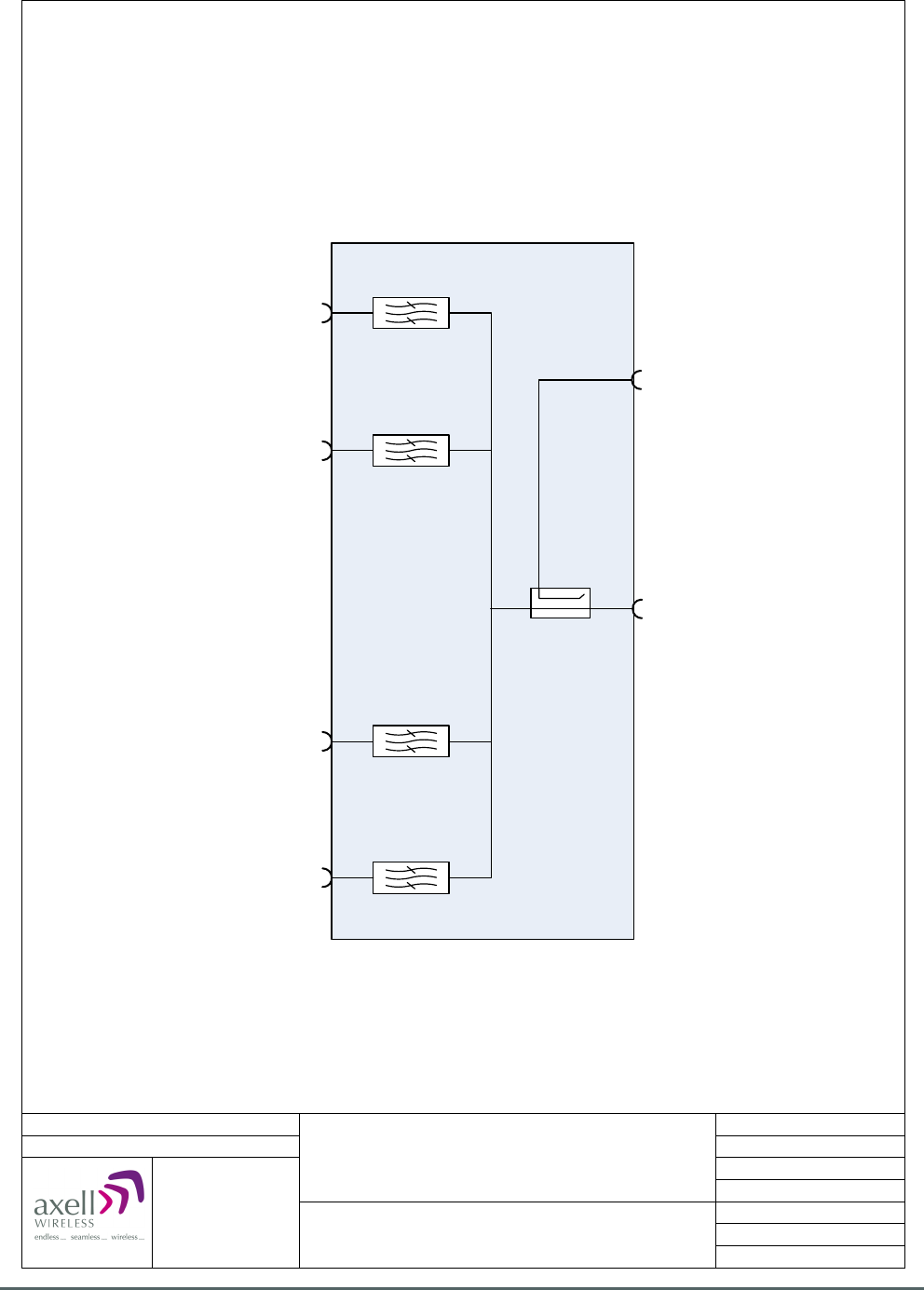
Axell Wireless Limited
Technical Literature
WMATA CRCS Redundant Antenna System
General Overview
Document Number 60-228701HBK Issue No. 3 Date 28/05/2010 Page 56 of 114
02-016801
489.5-491.0 MHz
90-852330
30 dB
Port A, Band 1 D/L I/P from
8 Ch. Squelch Gated BDA 60-228704
Date: 23/11/2009
© AWL 2009
Page 1 of 1
A4
Issue: 1
Drawn by: EW/AJS
Not to Scale
Aerial House
Asheridge Road
Chesham
Buckinghamshire
HP5 2QD United Kingdom
Telephone: +44 (0) 1494 777000
Facsimile: +44 (0) 1494 777002
E-Mail: info@axellwireless.com
www.axellwireless.com
Quadplexer (DAS) 60-228706
System Diagram
02-016801
492.5-494.0 MHz
02-013401
496.3-496.7 MHz
02-013401
499.3-499.7 MHz
Port B, Band 1 U/L O/P to
8 Ch. Squelch Gated BDA 60-228704
Port D, Band 2 U/L O/P to
8 Ch. Squelch Gated BDA 60-228705
Port C, Band 2 D/L I/P from
8 Ch. Squelch Gated BDA 60-228705
Monitor Port
30dB coupled from D/L O/P
D/L O/P to DAS
U/L I/P from DAS
4.9.3. Quadplexer (DAS) 60-228706 System Diagram
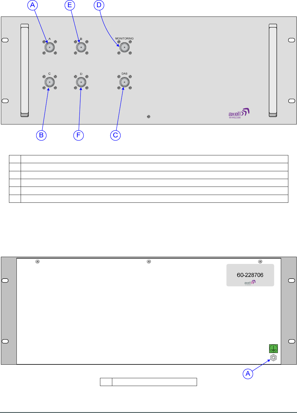
Axell Wireless Limited
Technical Literature
WMATA CRCS Redundant Antenna System
General Overview
Document Number 60-228701HBK Issue No. 3 Date 28/05/2010 Page 57 of 114
4.9.4. Quadplexer (DAS) 60-228706 Front View
A N type port “A”, Band 1 Downlink input from 8 Ch. Squelch Gated BDA 60-228704
B N type port “C”, Band 2 Downlink input from 8 Ch. Squelch Gated BDA 60-228705
C N type port “DAS”, Downlink output to and Uplink input from the DAS
D N type port “MONITORING”, 30dB test/monitor port coupled from the Downlink O/P path
E N type port “B”, Band 1 Uplink output to 8 Ch. Squelch Gated BDA 60-228704
F N type port “D”, Band 2 Uplink output to 8 Ch. Squelch Gated BDA 60-228705
4.9.5. Quadplexer (DAS) 60-228706 Rear View
A Earthing connection

Axell Wireless Limited
Technical Literature
WMATA CRCS Redundant Antenna System
General Overview
Document Number 60-228701HBK Issue No. 3 Date 28/05/2010 Page 58 of 114
4.10. PSU Housing Shelf 96-300090
This is a 1U, 19” Rack Mount shelf housing two, 960W, fan cooled, AC mains driven PSU modules (96-
300091) the outputs of which are combined to provide a 24V DC supply to the other chassis in the system.
The DC leads connected to the output terminals (annotated “B” and “C” in section 4.10.2.) are terminated
with right-angle XLR female connectors which mate with corresponding panel mounting male XLR
connectors on the front panels of those units which require a DC input.
4.10.1. PSU module 96-300091 Specification
Output
DC Voltage
24V
Rated Current
40A
Current Range
0 ~ 40A
Rated Power
960W
Ripple & Noise (max.)
200mVp-p
Voltage Adj. Range
23.2 ~ 24.8V
Voltage Tolerance
±1.0%
Line Regulation
±0.5%
Load Regulation
±0.5%
Setup, Rise Time
1000ms, 60ms/230V AC at full load
Hold Time (Typ.)
16ms/230V AC at full load
Input
Voltage Range
90 ~ 264V AC
127 ~ 370V DC
Frequency Range
47 ~ 63Hz
Efficiency (Typ.)
87%
AC Current (Typ.)
10.5A/115V AC
5.5A/230V AC
Inrush Current (Typ.)
Cold Start 50A
Leakage Current
<1.1mA / 230VAC
Protection
Over Load
105 ~ 125% rated output power
Protection type : Constant current limiting, recovers automatically
after fault condition is removed
Over Voltage
26.4 ~ 32.4V
Protection type : Shut down o/p voltage, re-power on to recover
Over Temperature
75 5°C ±5°C (TSW1) Detect on heatsink of power transistor
85 5°C ±5°C (TSW2) Detect on heatsink of power diode
Protection type : Shut down o/p voltage, recovers automatically
after temperature goes down
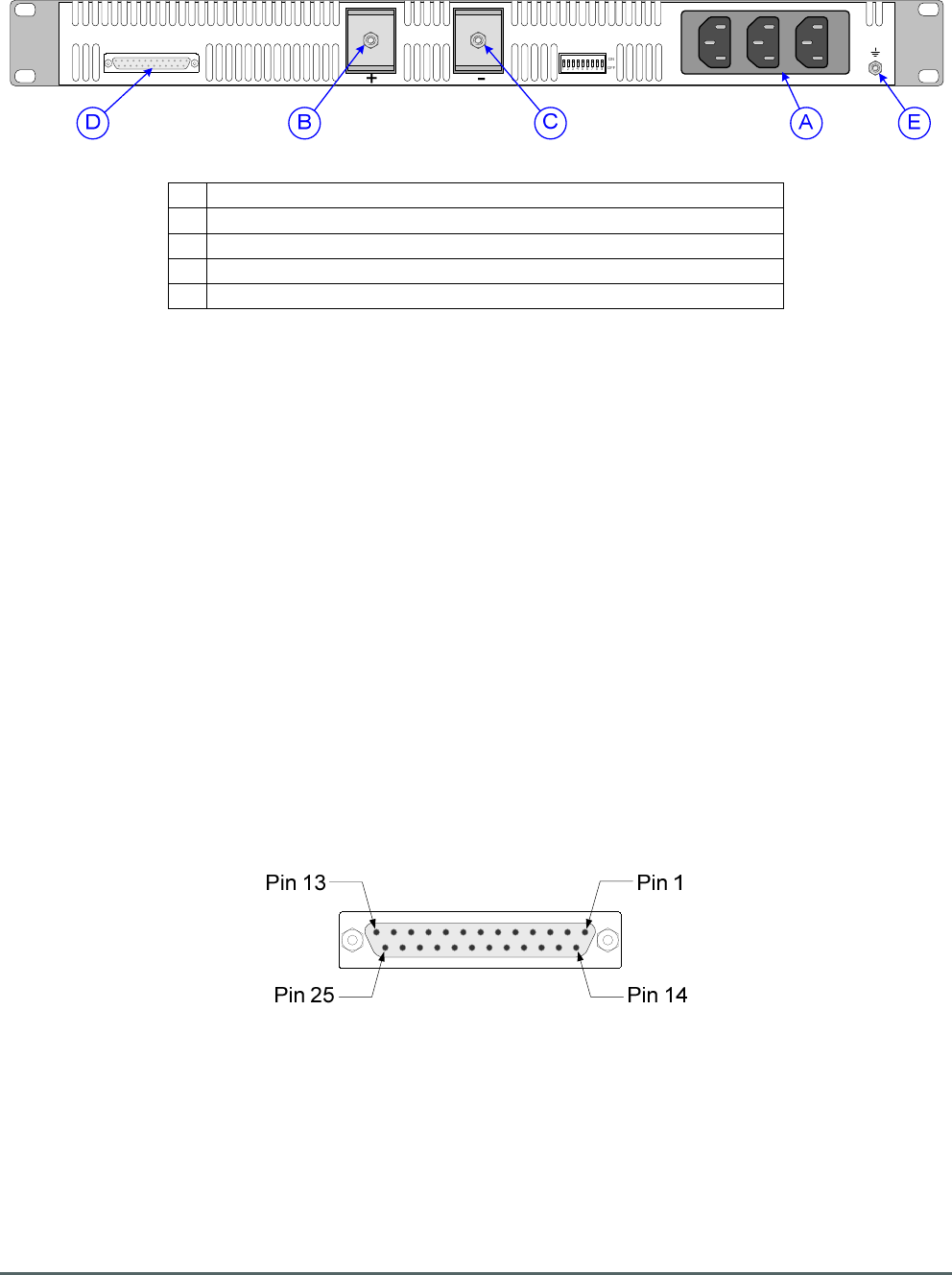
Axell Wireless Limited
Technical Literature
WMATA CRCS Redundant Antenna System
General Overview
Document Number 60-228701HBK Issue No. 3 Date 28/05/2010 Page 59 of 114
4.10.2. PSU Module Chassis 96-300090 Rear View
A AC inputs
B 24V DC terminal (connects to rack 24V busbar)
C
0V DC terminal (connects to rack 0V busbar)
D
Alarm output to Krone terminal block on rack
E Earthing connector
4.10.3. PSU Module Chassis 96-300090 Alarm Wiring
25 pin “D” panel socket, local alarm/control output to Krone terminal block on rack (annotated “D” in section
4.10.2.)
Pin 1 ON/OFF PSU A
Pin 2 AC OK PSU A
Pin 3 DC OK PSU A
Pin 5 T-ALARM PSU A
Pin 9 AC OK PSU B
Pin 8 ON/OFF PSU B
Pin 10 DC OK PSU B
Pin 12 T-ALARM PSU B
Pin 21 -S -ve SENSING
Pin 20 +S +ve SENSING
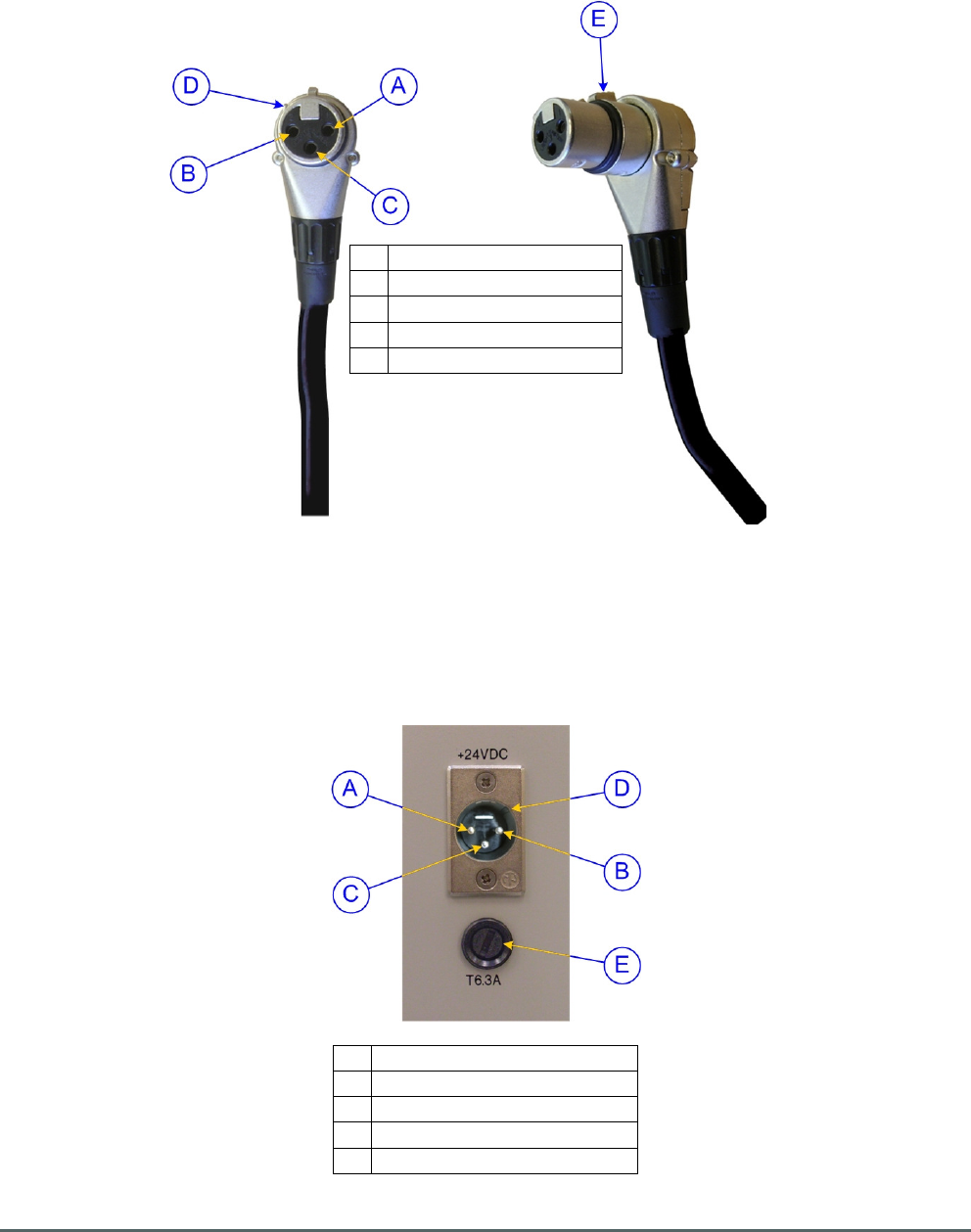
Axell Wireless Limited
Technical Literature
WMATA CRCS Redundant Antenna System
General Overview
Document Number 60-228701HBK Issue No. 3 Date 28/05/2010 Page 60 of 114
4.10.4. DC Connector Details
4.10.4.1. DC Inlet Free Socket
These are the free sockets that are connected to the rack busbars
A Pin 1, 24V (Red Wire)
B Pin 2, 0V (Black wire)
C
Pin 3, not connected
D
Guide key
E Locking/release lug
5.10.4.2. Typical DC Inlet Panel Plug
Typical DC Inlet Panel Plug showing pin allocations for the rack equipment shelves
A Pin 1, 24V (Red Wire)
B Pin 2, 0V (Black wire)
C
Pin 3, not connected
D
Guide keyway
E Fuse access

Axell Wireless Limited
Technical Literature
WMATA CRCS Redundant Antenna System
General Overview
Document Number 60-228701HBK Issue No. 3 Date 28/05/2010 Page 61 of 114
5. 60-228901 - WMATA Gallery Place Station CRAS System
The WMATA Gallery Place Station CRAS System consists of the following equipment mounted in two 41U,
19” equipment housing racks, each rack is loaded with equipment on both the front and rear aspects.
Rack 1 (part No, 60-228902)
Front:
Part No. 96-300090 PSU Housing Shelf
Contains Qty. 2, Part No. 96-300091 PSU Modules
Part No. 60-228703 Dual Fiber Optic Unit
Part No. 60-228905 RF Failover Switch Unit
Part No. 60-228907 Combiner Unit
Part No. 60-228904 16 Ch. DSP U/L Squelch Gate (No. 22)
Part No. 60-228904 16 Ch. DSP U/L Squelch Gate (No. 23)
Part No. 60-228904 16 Ch. DSP U/L Squelch Gate (No. 24)
Part No. 60-228904 16 Ch. DSP U/L Squelch Gate (No. 25)
Part No. 60-228904 16 Ch. DSP U/L Squelch Gate (No. 26)
Rear:
Part No. 60-228909 Combiner Unit
Part No. 60-228904 16 Ch. DSP U/L Squelch Gate (No. 15)
Part No. 60-228904 16 Ch. DSP U/L Squelch Gate (No. 16)
Part No. 60-228904 16 Ch. DSP U/L Squelch Gate (No. 17)
Part No. 60-228904 16 Ch. DSP U/L Squelch Gate (No. 18)
Part No. 60-228904 16 Ch. DSP U/L Squelch Gate (No. 19)
Part No. 60-228904 16 Ch. DSP U/L Squelch Gate (No. 20)
Part No. 60-228904 16 Ch. DSP U/L Squelch Gate (No. 21)
Rack 2 (part No, 60-228903)
Front:
Part No. 96-300090 PSU Housing Shelf
Contains Qty. 2, Part No. 96-300091 PSU Modules
Part No. 60-228906 Combiner Unit
Part No. 60-228904 16 Ch. DSP U/L Squelch Gate (No. 1)
Part No. 60-228904 16 Ch. DSP U/L Squelch Gate (No. 2)
Part No. 60-228904 16 Ch. DSP U/L Squelch Gate (No. 3)
Part No. 60-228904 16 Ch. DSP U/L Squelch Gate (No. 4)
Part No. 60-228904 16 Ch. DSP U/L Squelch Gate (No. 5)
Part No. 60-228904 16 Ch. DSP U/L Squelch Gate (No. 6)
Part No. 60-228904 16 Ch. DSP U/L Squelch Gate (No. 7)
Rear:
Part No. 60-228908 Combiner Unit
Part No. 60-228904 16 Ch. DSP U/L Squelch Gate (No. 8)
Part No. 60-228904 16 Ch. DSP U/L Squelch Gate (No. 9)
Part No. 60-228904 16 Ch. DSP U/L Squelch Gate (No. 10)
Part No. 60-228904 16 Ch. DSP U/L Squelch Gate (No. 11)
Part No. 60-228904 16 Ch. DSP U/L Squelch Gate (No. 12)
Part No. 60-228904 16 Ch. DSP U/L Squelch Gate (No. 13)
Part No. 60-228904 16 Ch. DSP U/L Squelch Gate (No. 14)
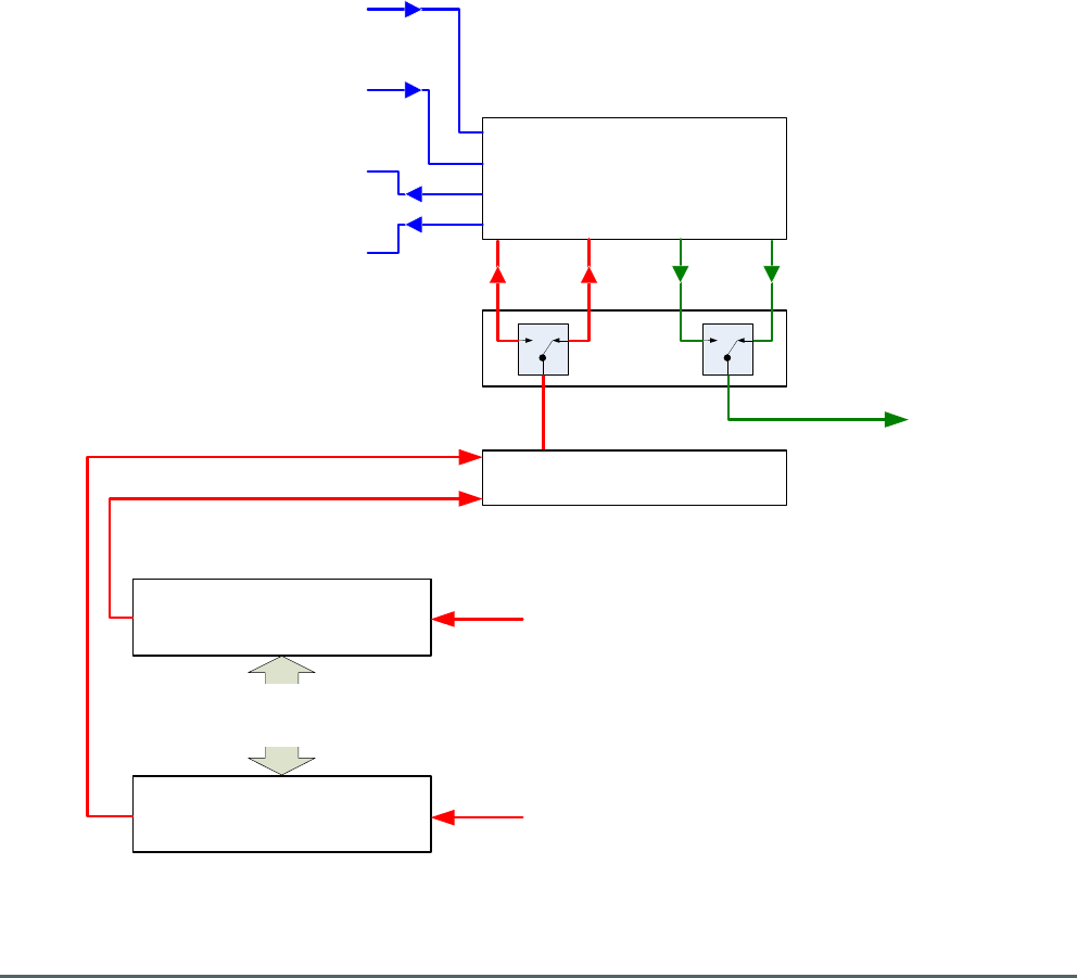
Axell Wireless Limited
Technical Literature
WMATA CRCS Redundant Antenna System
General Overview
Document Number 60-228701HBK Issue No. 3 Date 28/05/2010 Page 62 of 114
RF/Optical
RF
Relay
16 Ch. DSP U/L
Squelch Gate 1
16 Ch. DSP U/L
Squelch Gate 26
Primary Downlink Optical Input from
Jackson Graham Building system
Redundant Downlink Optical Input
from Carmen Turner Facility system
Primary Uplink Optical Output to
Jackson Graham Building system
Redundant Uplink Optical Output to
Carmen Turner Facility system
RF Downlink Output
to CRCS Donor Unit
RF Uplink Input
from CRCS Donor Unit
RF Uplink Input
from CRCS Donor Unit
RF Combiner
16 Ch. DSP U/L
Squelch Gates 2 to 25
The Gallery Place Station CRAS System receives a Primary optical Downlink from the Jackson Graham
Building CRAS System and a Redundant optical Downlink from the Carmen Turner Facility CRAS System,
both optical Downlink feeds enter the Gallery Place Station CRAS System and are demodulated to RF.
Normally the Primary Downlink signal from the Jackson Graham Building is passed on to the CRCS Donor
Unit but if the signal strength of the Primary Downlink path falls below a pre-set threshold then RF relays in
the Gallery Place Station CRAS System automatically switch to the Redundant signal path from the Carmen
Turner Facility CRAS System.
26 Uplink paths are received from the CRCS Donor Unit; each path is fed into a Channelized DSP U/L
Squelch Gate and the outputs from those 26 units are combined and modulated onto optical signals, the
Primary optical Uplink being fed to the Jackson Graham Building CRAS System and in the event that the
main signal path is switched out, the Redundant optical Uplink path is fed to the Carmen Turner Facility
CRAS System
5.1. Simplified System Sketch
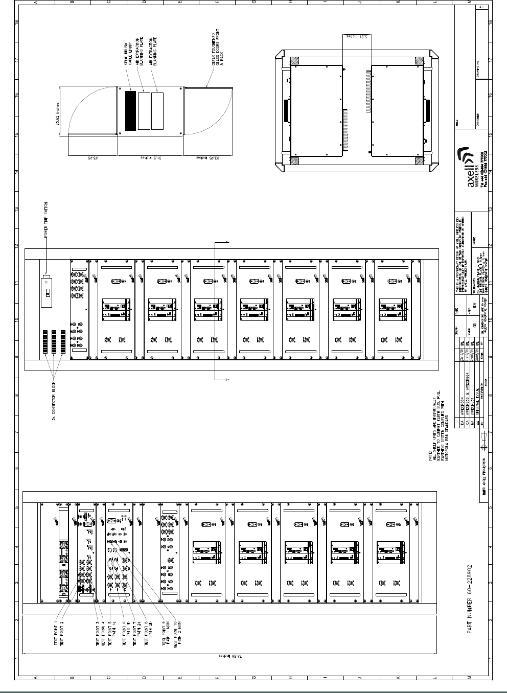
Axell Wireless Limited
Technical Literature
WMATA CRCS Redundant Antenna System
General Overview
Document Number 60-228701HBK Issue No. 3 Date 28/05/2010 Page 63 of 114
WMATA GALLERY PLACE STATION GATED U/L
RACK LAYOUT CABINET 1
60-228952
PL 28/08/09
AS STATED
FRONT ELEVATION
(DOOR REMOVED)
SCALE 1:4
REAR ELEVATION
(DOOR REMOVED)
SCALE 1:4
60-228907
2U COMBINER UNIT
1U BLANK
1U BLANK
1U BLANK
1U BLANK
1U BLANK
1U BLANK
2U BLANK
96-300090 + 96-300091x2
1U PSU SHELF
PLAN VIEW
SCALE 1:10
SECTION VIEW ON A-A
SCALE 1:4
A
60-228905
3U RF FAIL OVER UNIT
60-228909
2U COMBINER UNIT
1U BLANK
1U BLANK
1U BLANK
1U BLANK
1U BLANK
1U BLANK
A
60-228703
2U DUAL F/O TRANSCEIVER UNIT
1U BLANK
1U BLANK
1U BLANK
1U BLANK
1U BLANK
2U BLANK
60-228904
4U 16 CHANNEL
U/L GATING UNIT
60-228904
4U 16 CHANNEL
U/L GATING UNIT
60-228904
4U 16 CHANNEL
U/L GATING UNIT
60-228904
4U 16 CHANNEL
U/L GATING UNIT
60-228904
4U 16 CHANNEL
U/L GATING UNIT
60-228904
4U 16 CHANNEL
U/L GATING UNIT
60-228904
4U 16 CHANNEL
U/L GATING UNIT
60-228904
4U 16 CHANNEL
U/L GATING UNIT
60-228904
4U 16 CHANNEL
U/L GATING UNIT
60-228904
4U 16 CHANNEL
U/L GATING UNIT
60-228904
4U 16 CHANNEL
U/L GATING UNIT
60-228904
4U 16 CHANNEL
U/L GATING UNIT
5.2. Rack 1 Equipment Layout
Drawing number 60-228952
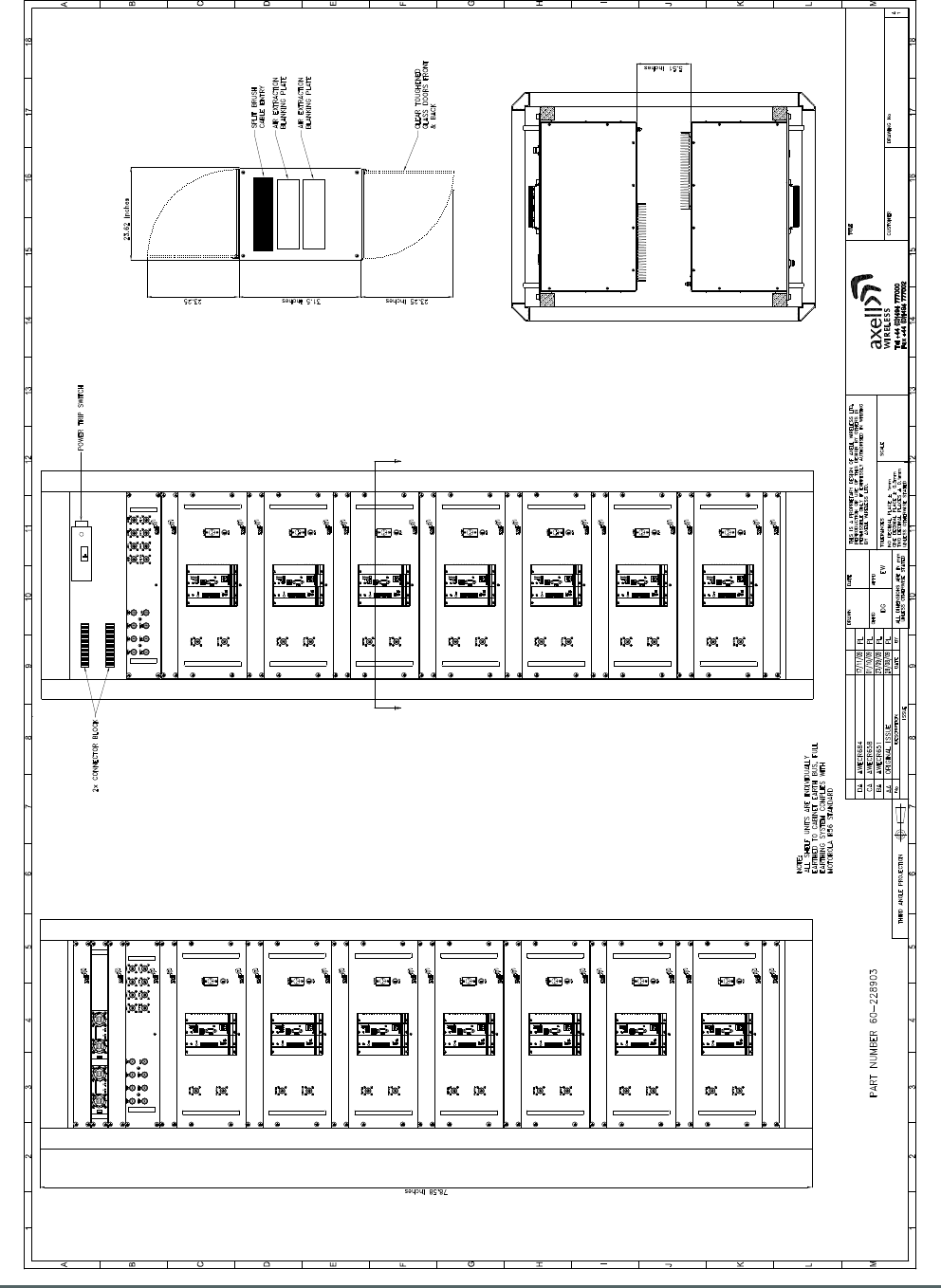
Axell Wireless Limited
Technical Literature
WMATA CRCS Redundant Antenna System
General Overview
Document Number 60-228701HBK Issue No. 3 Date 28/05/2010 Page 64 of 114
WMATA GALLERY PLACE STATION GATED U/L
RACK LAYOUT CABINET 2
60-228953
PL 28/08/09
AS STATED
FRONT ELEVATION
(DOOR REMOVED)
SCALE 1:4
REAR ELEVATION
(DOOR REMOVED)
SCALE 1:4
1U BLANK
1U BLANK
1U BLANK
1U BLANK
1U BLANK
1U BLANK
1U BLANK
PLAN VIEW
SCALE 1:10
SECTION VIEW ON A-A
SCALE 1:4
A
1U BLANK
1U BLANK
1U BLANK
1U BLANK
1U BLANK
1U BLANK
1U BLANK
A
96-300090 + 96-300091x2
1U PSU SHELF
60-228906
2U COMBINER UNIT
60-228908
2U COMBINER UNIT
60-228904
4U 16 CHANNEL
U/L GATING UNIT
1U BLANK
1U BLANK
60-228904
4U 16 CHANNEL
U/L GATING UNIT
60-228904
4U 16 CHANNEL
U/L GATING UNIT
60-228904
4U 16 CHANNEL
U/L GATING UNIT
60-228904
4U 16 CHANNEL
U/L GATING UNIT
60-228904
4U 16 CHANNEL
U/L GATING UNIT
60-228904
4U 16 CHANNEL
U/L GATING UNIT
60-228904
4U 16 CHANNEL
U/L GATING UNIT
60-228904
4U 16 CHANNEL
U/L GATING UNIT
60-228904
4U 16 CHANNEL
U/L GATING UNIT
60-228904
4U 16 CHANNEL
U/L GATING UNIT
60-228904
4U 16 CHANNEL
U/L GATING UNIT
60-228904
4U 16 CHANNEL
U/L GATING UNIT
60-228904
4U 16 CHANNEL
U/L GATING UNIT
5.3. Rack 2 Equipment Layout
Drawing number 60-228953
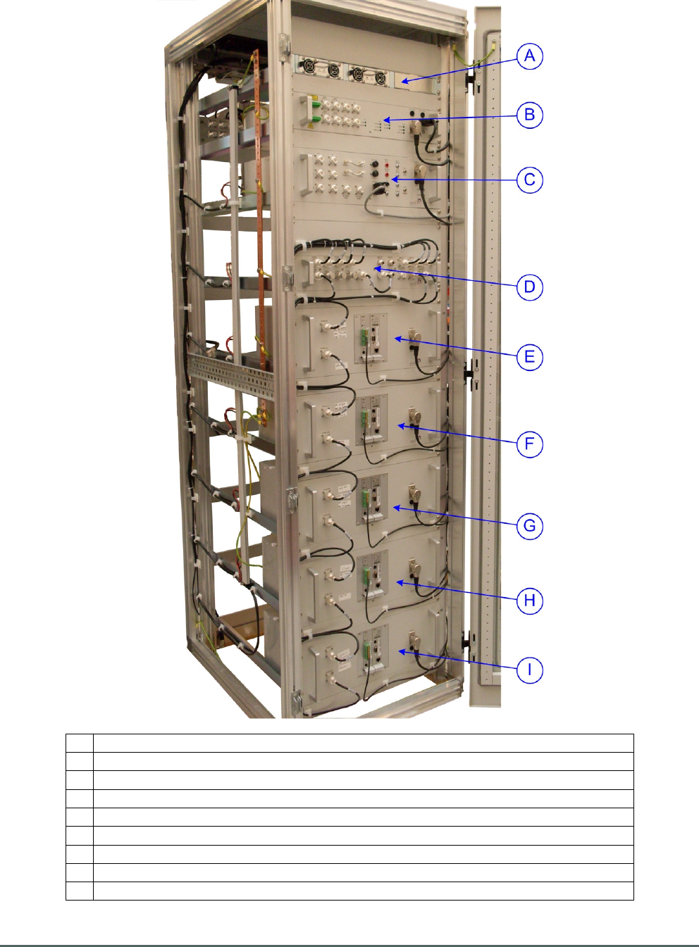
Axell Wireless Limited
Technical Literature
WMATA CRCS Redundant Antenna System
General Overview
Document Number 60-228701HBK Issue No. 3 Date 28/05/2010 Page 65 of 114
5.4. Rack 1 Front View
A PSU Housing Shelf 96-300090 + Qty. 2, Part No. 96-300091 PSU Modules
B Dual Fiber Optic Unit 60-228703
C RF Failover Switch Unit 60-228905
D Combiner Unit 60-228907
E 16 Ch. DSP U/L Squelch Gate No. 22
F 16 Ch. DSP U/L Squelch Gate No. 23
G
16 Ch. DSP U/L Squelch Gate No. 24
H 16 Ch. DSP U/L Squelch Gate No. 25
I 16 Ch. DSP U/L Squelch Gate No. 26
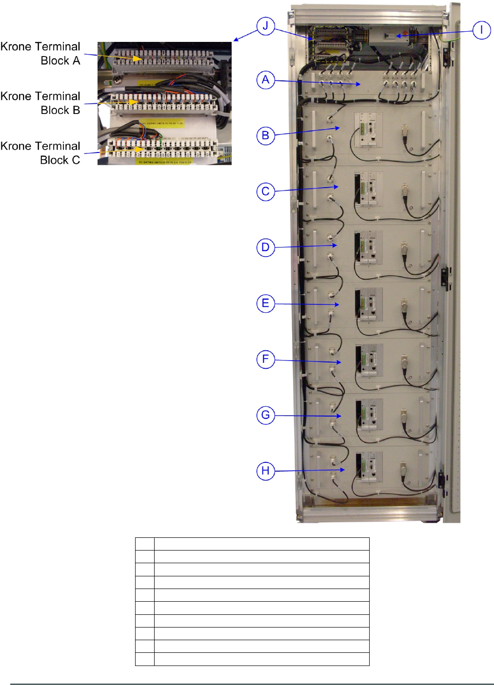
Axell Wireless Limited
Technical Literature
WMATA CRCS Redundant Antenna System
General Overview
Document Number 60-228701HBK Issue No. 3 Date 28/05/2010 Page 66 of 114
5.5. Rack 1 Rear View
A Combiner Unit 60-228909
B 16 Ch. DSP U/L Squelch Gate No. 15
C
16 Ch. DSP U/L Squelch Gate No. 16
D
16 Ch. DSP U/L Squelch Gate No. 17
E 16 Ch. DSP U/L Squelch Gate No. 18
F 16 Ch. DSP U/L Squelch Gate No. 19
G
16 Ch. DSP U/L Squelch Gate No. 20
H
16 Ch. DSP U/L Squelch Gate No. 21
I AC Circuit Breaker
J Krone terminal blocks for alarm outputs
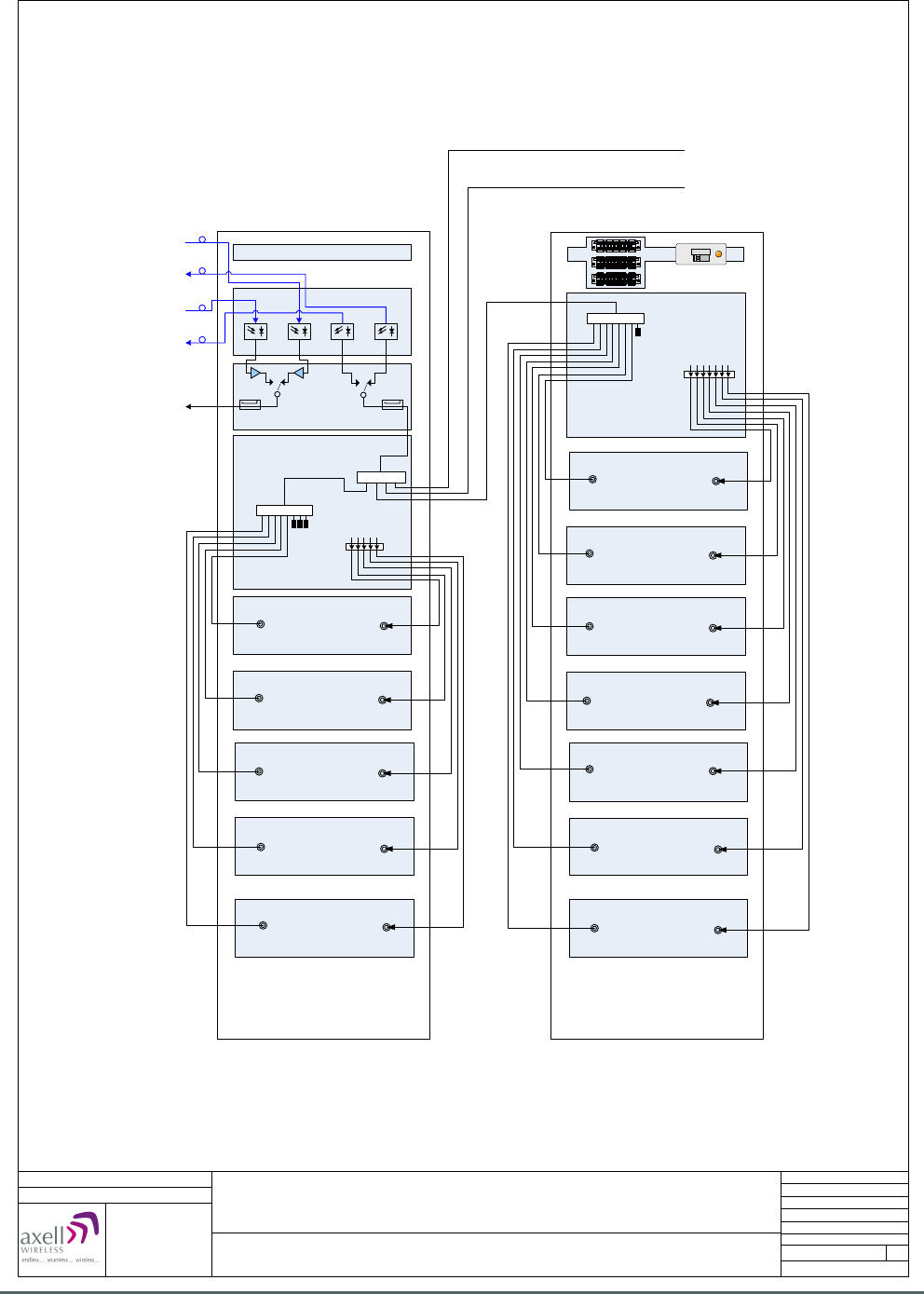
Axell Wireless Limited
Technical Literature
WMATA CRCS Redundant Antenna System
General Overview
Document Number 60-228701HBK Issue No. 3 Date 28/05/2010 Page 67 of 114
WMATA Gallery Place Station System
Rack 1 Front and Rear Views
Date: 30/11/2009
Page 1 of 1
A3
Issue: 1
Drawn by: EW/AJS
Not to Scale
Aerial House
Asheridge Road
Chesham
Buckinghamshire
HP5 2QD United Kingdom
Telephone: +44 (0) 1494 777000
Facsimile: +44 (0) 1494 777002
E-Mail: info@axellwireless.com
www.axellwireless.com
© AWL 2009
PSU Shelf 96-300090 + 2 x 96-300091
16 Ch. DSP U/L Squelch Gate
60-228904
22
16 Ch. DSP U/L Squelch Gate
60-228904
23
16 Ch. DSP U/L Squelch Gate
60-228904
24
16 Ch. DSP U/L Squelch Gate
60-228904
25
16 Ch. DSP U/L Squelch Gate
60-228904
26
16 Ch. DSP U/L Squelch Gate
60-228904
15
16 Ch. DSP U/L Squelch Gate
60-228904
16
16 Ch. DSP U/L Squelch Gate
60-228904
17
16 Ch. DSP U/L Squelch Gate
60-228904
18
16 Ch. DSP U/L Squelch Gate
60-228904
19
16 Ch. DSP U/L Squelch Gate
60-228904
20
16 Ch. DSP U/L Squelch Gate
60-228904
21
Dual FO Unit 60-228703
RF Failover Switch 60-228905
5 U/L Combiner Unit
(22-26) 60-228907
D/L Output to
CRCS donor unit
Redundant F/O D/L I/P from
Carmen Turner Facility
Primary F/O D/L I/P from
Jackson Graham Building
Sum of 1-26
Sum of 22-26
(LINK)
Sum of 15-21
Mon Mon
7 U/L Combiner Unit
(15-21) 60-228909
U/L Inputs from
CRCS donor unit
Seg. 22-26
U/L Inputs from
CRCS donor unit
Seg. 15-21
06-001901
06-001901
06-001801
RACK 1 FRONT RACK 1 REAR
Primary F/O U/L O/P to
Jackson Graham Building
Redundant F/O U/L O/P to
Carmen Turner Facility
Uplink input from Rack 2 (Front)
Sum of 16 Ch. DSP U/L Squelch Gates 1 - 7
Uplink input from Rack 2 (Rear)
Sum of 16 Ch. DSP U/L Squelch Gates 8 - 15
Alarm output Krone
terminal blocks
AC Circuit
breaker
5.6. Rack 1 elevations showing RF connections
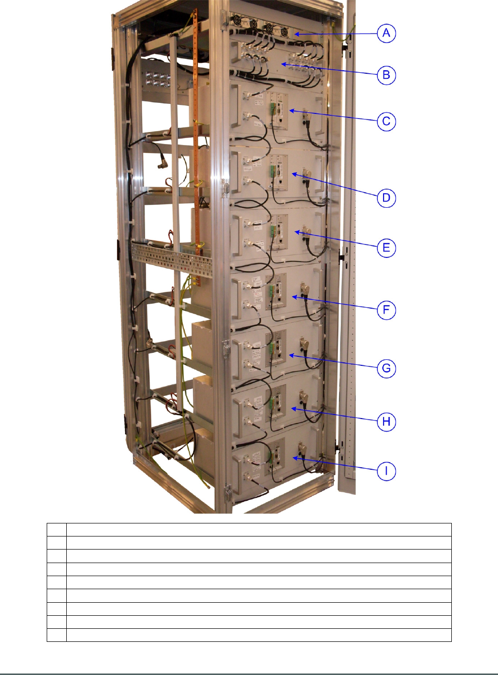
Axell Wireless Limited
Technical Literature
WMATA CRCS Redundant Antenna System
General Overview
Document Number 60-228701HBK Issue No. 3 Date 28/05/2010 Page 68 of 114
5.7. Rack 2 Front View
A PSU Housing Shelf 96-300090 + Qty. 2, Part No. 96-300091 PSU Modules
B Combiner Unit 60-228906
C 16 Ch. DSP U/L Squelch Gate No. 1
D 16 Ch. DSP U/L Squelch Gate No. 2
E 16 Ch. DSP U/L Squelch Gate No. 3
F 16 Ch. DSP U/L Squelch Gate No. 4
G
16 Ch. DSP U/L Squelch Gate No. 5
H 16 Ch. DSP U/L Squelch Gate No. 6
I 16 Ch. DSP U/L Squelch Gate No. 7
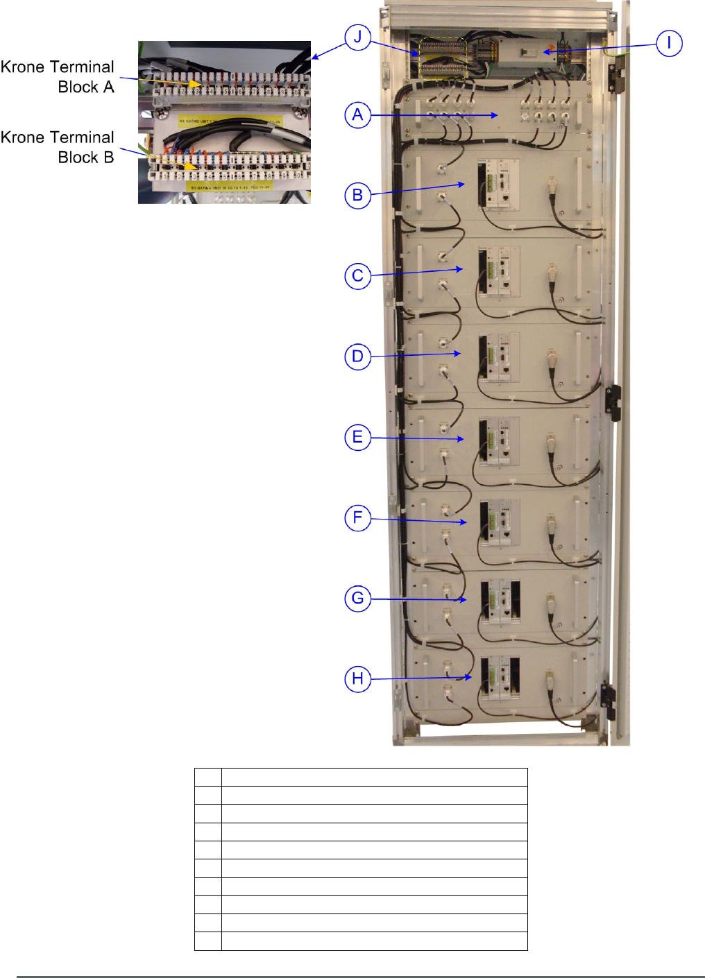
Axell Wireless Limited
Technical Literature
WMATA CRCS Redundant Antenna System
General Overview
Document Number 60-228701HBK Issue No. 3 Date 28/05/2010 Page 69 of 114
5.8. Rack 2 Rear View
A Combiner Unit 60-228908
B 16 Ch. DSP U/L Squelch Gate No. 8
C
16 Ch. DSP U/L Squelch Gate No. 9
D
16 Ch. DSP U/L Squelch Gate No. 10
E 16 Ch. DSP U/L Squelch Gate No. 11
F 16 Ch. DSP U/L Squelch Gate No. 12
G
16 Ch. DSP U/L Squelch Gate No. 13
H
16 Ch. DSP U/L Squelch Gate No. 14
I AC Circuit Breaker
J Krone terminal blocks for alarm outputs
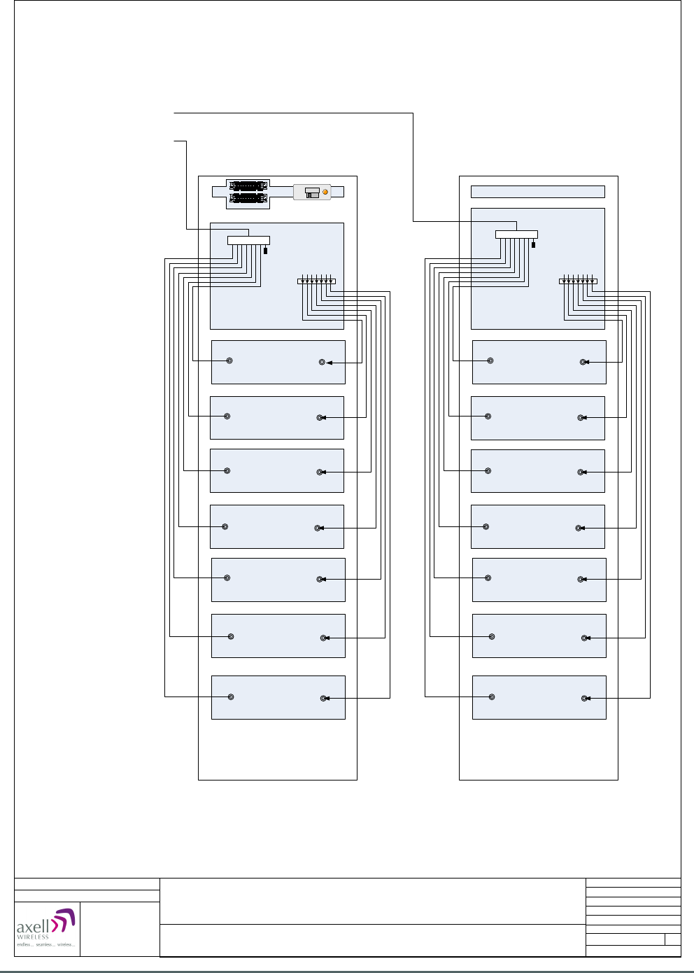
Axell Wireless Limited
Technical Literature
WMATA CRCS Redundant Antenna System
General Overview
Document Number 60-228701HBK Issue No. 3 Date 28/05/2010 Page 70 of 114
WMATA Gallery Place Station System
Rack 2 Front and Rear Views
Date: 03/12/2009
Page 1 of 1
A3
Issue: 1
Drawn by: EW/AJS
Not to Scale
Aerial House
Asheridge Road
Chesham
Buckinghamshire
HP5 2QD United Kingdom
Telephone: +44 (0) 1494 777000
Facsimile: +44 (0) 1494 777002
E-Mail: info@axellwireless.com
www.axellwireless.com
© AWL 2009
Uplink output from Rack 2 (Front)
Sum of 16 Ch. DSP U/L Squelch Gates 1 - 7
Uplink output from Rack 2 (Rear)
Sum of 16 Ch. DSP U/L Squelch Gates 8 - 14
16 Ch. DSP U/L Squelch Gate
60-228904
8
16 Ch. DSP U/L Squelch Gate
60-228904
9
16 Ch. DSP U/L Squelch Gate
60-228904
10
16 Ch. DSP U/L Squelch Gate
60-228904
11
16 Ch. DSP U/L Squelch Gate
60-228904
12
16 Ch. DSP U/L Squelch Gate
60-228904
13
16 Ch. DSP U/L Squelch Gate
60-228904
14
Sum of 8-14
PSU Shelf 96-300090 + 2 x 96-300091
16 Ch. DSP U/L Squelch Gate
60-228904
1
16 Ch. DSP U/L Squelch Gate
60-228904
2
16 Ch. DSP U/L Squelch Gate
60-228904
3
16 Ch. DSP U/L Squelch Gate
60-228904
4
16 Ch. DSP U/L Squelch Gate
60-228904
5
16 Ch. DSP U/L Squelch Gate
60-228904
6
16 Ch. DSP U/L Squelch Gate
60-228904
7
Sum of 1-7
7 U/L Combiner Unit
(8-14) 60-228908
7 U/L Combiner Unit
(1-7) 60-228906
U/L Inputs from
CRCS donor unit
Seg. 8-14
06-001901
06-001901
U/L Inputs from
CRCS donor unit
Seg. 1-7
RACK 2 BACK RACK 2 FRONT
Alarm output Krone
terminal blocks
AC Circuit
breaker
5.9. Rack 2 elevations showing RF connections
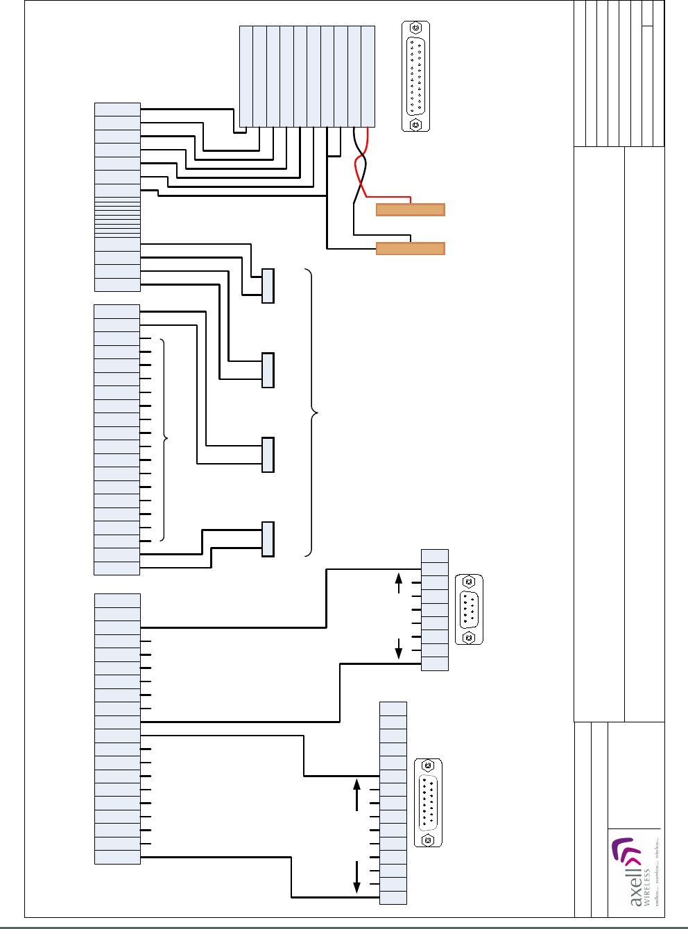
Axell Wireless Limited
Technical Literature
WMATA CRCS Redundant Antenna System
General Overview
Document Number 60-228701HBK Issue No. 3 Date 28/05/2010 Page 71 of 114
WMATA Gallery Place Station
Rack 1, Part No. 60-228902
Alarm Wiring Diagram
Date: 04/12/2009
Page 1 of 3
A4
Issue: 2
Drawn by: EW
Not to Scale
Aerial House
Asheridge Road
Chesham
Buckinghamshire
HP5 2QD United Kingdom
Telephone: +44 (0) 1494 777000
Facsimile: +44 (0) 1494 777002
E-Mail: info@axellwireless.com
www.axellwireless.com
© AWL 2009
60-228904
No. 15
60-228904
No. 24
25 way “D” socket on PSU
Housing Shelf 96-300090
Pin 2 AC OK PSU A
Pin 9 AC OK PSU B
Pin 3 DC OK PSU A
Pin 10 DC OK PSU B
Pin 5 T-ALARM PSU A
Pin 12 T-ALARM PSU B
Pin 1 ON/OFF PSU A
Pin 8 ON/OFF PSU B
Pin 21 -S SENSE
Pin 20 +S SENSE
1
1
2
2
3
3
4
4
5
5
6
6
7
7
8
8
9
9
0
0
Krone Terminal Block A Krone Terminal Block B
1
1
2
2
7
8
8
9
9
0
0
Krone Terminal Block C
Alarm outputs from terminals 7 & 8 of External
Alarm and Battery Modules J1161030 on front faces
of 16 Ch. DSP U/L Squelch Gates 60-228904
1
1
2
2
3
3
4
4
5
5
6
6
7
7
8
8
9
9
0
0
60-228904
Nos. 16 to 23
60-228904
No. 25
60-228904
No. 26
+ve
busbar
-ve
busbar
15 way “D” plug,
alarm output from
Dual Fibre Optic Unit
60-228703
1
15
6
5
4
3
2
1
10
9
8
7
15
14
13
12
11
Pins 1 to 10
1
9
9 way “D” plug,
alarm output from
RF Failover Switch
Unit 60-228905
6
5
4
3
2
1
9
8
7
Pins 1 to 8
1
25
5.10. Rack Alarm Wiring Diagrams
5.10.1. Rack 1 Alarm Wiring
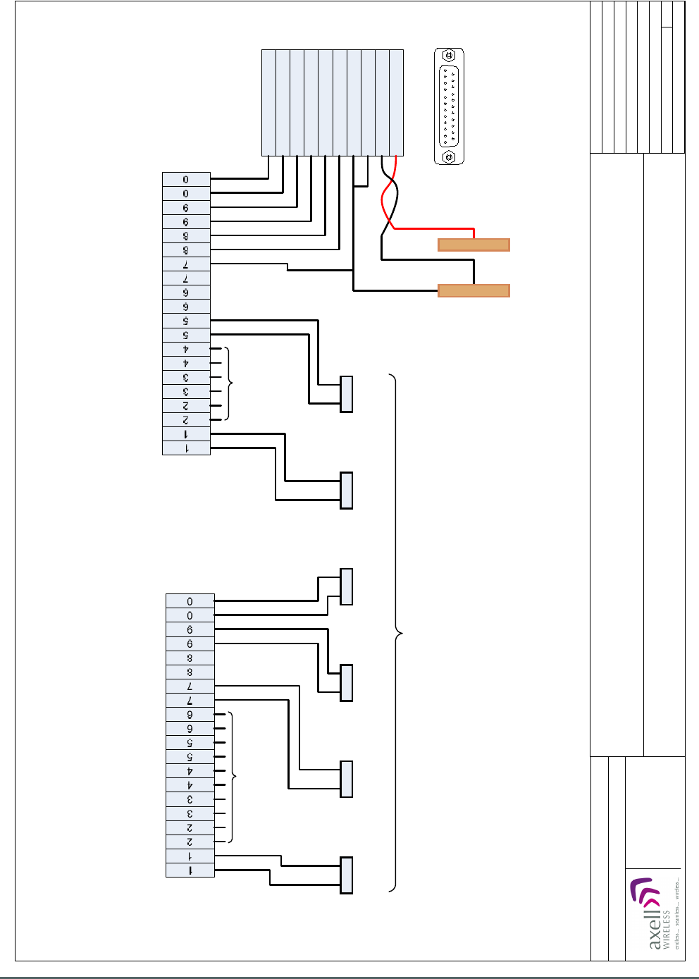
Axell Wireless Limited
Technical Literature
WMATA CRCS Redundant Antenna System
General Overview
Document Number 60-228701HBK Issue No. 3 Date 28/05/2010 Page 72 of 114
Pin 1 ON/OFF PSU A
Pin 8 ON/OFF PSU B
Pin 21 -S SENSE
Pin 20 +S SENSE
Pin 2 AC OK PSU A
Pin 9 AC OK PSU B
Pin 3 DC OK PSU A
Pin 10 DC OK PSU B
Pin 5 T-ALARM PSU A
Pin 12 T-ALARM PSU B
+ve
busbar
-ve
busbar
Krone Terminal Block A
WMATA Gallery Place Station
Rack 2, Part No. 60-228903
Alarm Wiring Diagram
Date: 04/12/2009
Page 2 of 3
A4
Issue: 2
Drawn by: EW
Not to Scale
Aerial House
Asheridge Road
Chesham
Buckinghamshire
HP5 2QD United Kingdom
Telephone: +44 (0) 1494 777000
Facsimile: +44 (0) 1494 777002
E-Mail: info@axellwireless.com
www.axellwireless.com
© AWL 2009
25 way “D” socket on PSU
Housing Shelf 96-300090
1
25
60-228904
No. 1
Alarm outputs from terminals 7 & 8 of External
Alarm and Battery Modules J1161030 on front faces
of 16 Ch. DSP U/L Squelch Gates 60-228904
60-228904
No. 7
60-228904
Nos. 2 to 6
60-228904
No. 8
60-228904
No. 14
60-228904
No. 9
60-228904
No. 10
60-228904
Nos. 11 to 13
Krone Terminal Block B
5.10.2. Rack 2 Alarm Wiring

Axell Wireless Limited
Technical Literature
WMATA CRCS Redundant Antenna System
General Overview
Document Number 60-228701HBK Issue No. 3 Date 28/05/2010 Page 73 of 114
5.11 Dual Fiber Optic Unit 60-228703 (Gallery Place Station)
Dual Fiber Optic Unit 60-228703 is built into a 2U, 19” rack-mount case.
The Primary Downlink optical signal from the Jackson Graham Building CRAS System enters the Dual Fiber
Optic Unit via the SC/APC optical port 1 “RX” (annotated “A” in section 5.11.4.) and passes into a Fiber
Optic Receiver Module 20-005501 which demodulates the Downlink optical signal to RF and the Downlink
RF signal then passes through a 20dB Directional Coupler 90-852420 which couples off a small portion of
the signal and feeds it to the N type port labeled “MON -20dB RX 1” (annotated “C” in section 5.11.4.) which
provides a 20dB test/monitor port for the Primary Downlink output. The Primary Downlink path then exits the
Dual Fiber Optic Unit for the RF Failover Switch Unit 60-228905 via the N type port labeled “RX 1”
(annotated “B” in section 5.11.4.)
The Redundant Downlink optical signal from the Carmen Turner Facility CRAS System enters the Dual
Fiber Optic Unit via the SC/APC optical port 2 “RX” (annotated “G” in section 5.11.4.) and passes into a
Fiber Optic Receiver Module 20-005501 which demodulates the Downlink signal to RF and the Downlink RF
signal then passes through a 20dB Directional Coupler 90-852420 which couples off a small portion of the
signal and feeds it to the N type port labeled “MON -20dB RX 2” (annotated “I” in section 5.11.4.) which
provides a 20dB test/monitor port for the Redundant Downlink output. The Redundant Downlink path then
exits the Dual Fiber Optic Unit for the RF Failover Switch Unit 60-228905 via the N type port labeled “RX 2”
(annotated “H” in section 5.11.4.)
The Primary RF Uplink from the RF Failover Switch Unit 60-228905 enters the Dual Fiber Optic Unit via the
N type port labeled “TX1” (annotated “D” in section 5.11.4.) and passes through a 20dB Directional Coupler
90-852420 which couples off a small portion of the signal and feeds it to the N type port labeled “MON -
20dB TX 1” (annotated “E” in section 5.11.4.) which provides a 20dB test/monitor port for the Primary Uplink
input.
The Primary Uplink path then passes into a Fiber Optic Transmitter Module 20-005401 where the RF signal
is modulated onto a laser and the optical signal thus produced then exits the Dual Fiber Optic Unit via the
SC/APC optical port 1 “TX” (annotated “F” in section 5.11.4.) and is transmitted to the Jackson Graham
Building CRAS System via a fiber optic cable link.
The Redundant RF Uplink from the RF Failover Switch Unit 60-228905 enters the Dual Fiber Optic Unit via
the N type port labeled “TX2” (annotated “J” in section 5.11.4.) and passes through a 20dB Directional
Coupler 90-852420 which couples off a small portion of the signal and feeds it to the N type port labeled
“MON -20dB TX 2” (annotated “K” in section 5.11.4.) which provides a 20dB test/monitor port for the
Redundant Uplink input.
The Redundant Uplink path then passes into a Fiber Optic Transmitter Module 20-005401 where the RF
signal is modulated onto a laser and the optical signal thus produced then exits the Dual Fiber Optic Unit via
the SC/APC optical port 2 “TX” (annotated “L” in section 5.11.4.) and is transmitted to the Carmen Turner
Facility CRAS System via a fiber optic cable link.
Dual Fiber Optic Unit 60-228703 is powered by a 24V DC supply from one of the PSU Modules 96-300091
in PSU Housing Shelf 96-300090, The 24V DC supply powers two on-board DC/DC converters 96-200024
arranged in a parallel dual redundant configuration, the outputs of which are combined by power diodes to
provide a 12V DC supply for the fiber optic modules within the unit
An alarm system is fitted to Dual Fiber Optic Unit 60-228703, each of the fiber optic modules carries its own
voltage-free contact alarm relay output which are summed at the 15 way “D” panel plug labeled “ALARM”
(annotated “EE” in section 5.11.4.)

Axell Wireless Limited
Technical Literature
WMATA CRCS Redundant Antenna System
General Overview
Document Number 60-228701HBK Issue No. 3 Date 28/05/2010 Page 74 of 114
5.11.1. Dual Fiber Optic Unit 60-228703 List of Major Sub-Components
Component
Part
Part Description Qty Per
Assembly
20-001601 12V Dual Relay Board 1
20-005401 Fiber Optic Transmitter Module 2
20-005501 Fiber Optic Receiver Module 2
96-110013 3.15 A Fuse 2
96-200024 DC/DC Converter 2
90-852420 20dB Directional Coupler 4
94-100003 Power Diode 3
5.11.2. Dual Fiber Optic Unit 60-228703 Specification
PARAMETER SPECIFICATION
RF Downlink
Frequency range
489.5MHz to 491.0MHz
496.3MHz to 496.7MHz
Coupling TX1 to Mon TX1
20 dB ± 1dB
Coupling TX2 to Mon TX2
20 dB ± 1dB
Optical Downlink
Wavelength
1310nm
TX(A) Optical TX Power
1-3 dBm
TX(B) Optical TX Power
1-3 dBm
Optical Uplink
Wavelength
1550nm
RX(A) Gain
>+15 dB
RX(A) Gain Set To
0 dB±0.5
RX(A) Alarm Threshold
< -10dBm
RX(B) Gain
>+15 dB
RX(A) Gain Set To
0 dB±0.5
RX(B) Alarm Threshold
< -10dBm
RF Uplink
Frequency range
499.3MHz to 499.7MHz
492.5MHz to 494.0MHz
Coupling RX1 to Mon RX1
20 dB ± 1dB
Coupling RX2 to Mon RX2
20 dB ± 1dB
General
Supply Voltage
12V DC or 24V DC
Current consumption
< 1.0A @ 24V DC input
< 1.5A @ 12V DC input
Alarm output
Summary volts free dry contact output
(Closed = Normal / Open = Alarm)
F/O TX1 contact output Pin 1 & 2
F/O TX2 contact output Pin 3 & 4
F/O RX1 contact output Pin 5 & 6
F/O RX1 contact output Pin 7 & 8
24V DC-DC contact output Pin 9 & 10**
**This alarm is not operational when the unit is powered from 12V DC
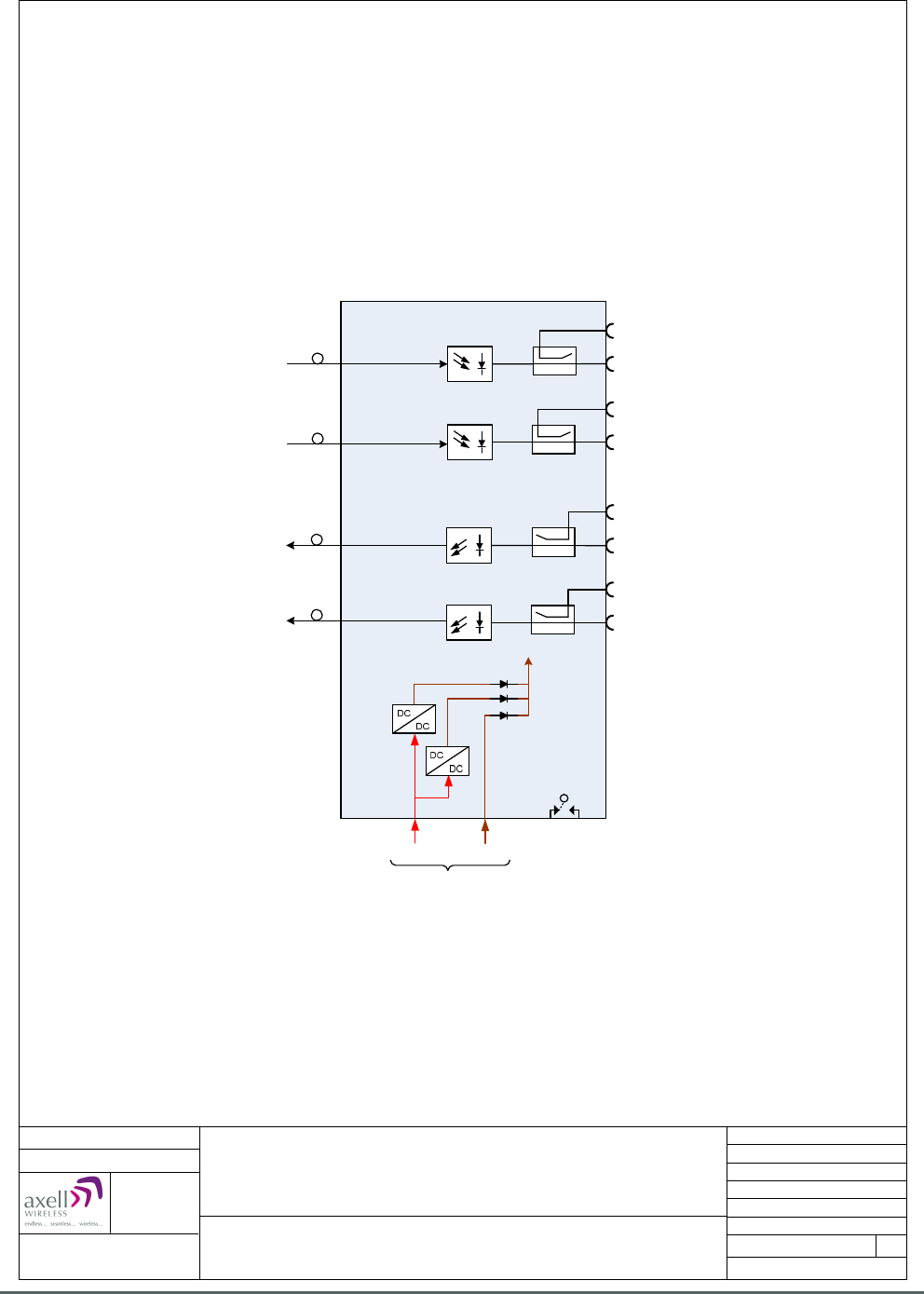
Axell Wireless Limited
Technical Literature
WMATA CRCS Redundant Antenna System
General Overview
Document Number 60-228701HBK Issue No. 3 Date 28/05/2010 Page 75 of 114
20-001601
Local Alarm
TX1 Monitor
TX2 Monitor
RF Port “RX1” Primary D/L O/P to
RF Failover Switch Unit 60-228905
RX1 Monitor
90-852420
90-852420
90-852420
90-852420
+24 VDC
2 x
96-200024
+12 VDC
3 x
94-100003
DC I/P
Optical Port 1 “RX”
Primary F/O D/L I/P from
Jackson Graham Building system
Optical Port 2 “RX”
Redundant F/O D/L I/P from
Carmen Turner Facility system
Optical Port 1 “TX”
Primary F/O U/L O/P to
Jackson Graham Building system
Optical Port 2 “TX”
Redundant F/O U/L O/P to
Carmen Turner Facility system
RF Port “RX2” Redundant D/L O/P to
RF Failover Switch Unit 60-228905
RX2 Monitor
RF Port “TX1” Primary U/L I/P from
RF Failover Switch Unit 60-228905
RF Port “TX2” Redundant U/L I/P from
RF Failover Switch Unit 60-228905
20-005401
20-005401
20-005501
20-005501
Dual Fibre Optic Unit 60-228703
System Diagram
(Gallery Place Station System)
Date: 8/12/2009
Aerial House
Asheridge Road
Chesham
Buckinghamshire
HP5 2QD
United Kingdom
© AWL 2009
Page 1 of 1
A4
Issue: 2
Drawn by: EW/AJS
Not to Scale
Telephone: +44 (0) 1494 777000
Facsimile: +44 (0) 1494 777002
E-Mail: info@axellwireless.com
www.axellwireless.com
5.11.3. Dual Fiber Optic Unit 60-228703 System Diagram

Axell Wireless Limited
Technical Literature
WMATA CRCS Redundant Antenna System
General Overview
Document Number 60-228701HBK Issue No. 3 Date 28/05/2010 Page 76 of 114
5.11.3.1. Dual Fiber Optic Unit 60-228703 Alarm Outputs
15 pin “D” panel plug “ALARM”, local alarm output to Krone terminal block “A” on rack (see section 5.5.)
Dry Contact Outputs (Closed = Normal / Open = Alarm)
F/O TX 1 (main), contact output Pin 1 & 2
F/O TX 2 (standby), contact output Pin 3 & 4
F/O RX 1 (main), contact output Pin 5 & 6
F/O RX 2 (standby), contact output Pin 7 & 8
24V DC>DC contact output Pin 9 & 10
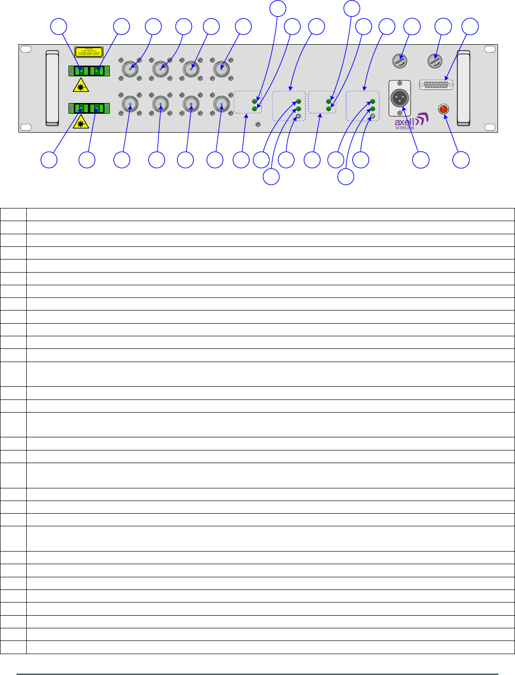
Axell Wireless Limited
Technical Literature
WMATA CRCS Redundant Antenna System
General Overview
Document Number 60-228701HBK Issue No. 3 Date 28/05/2010 Page 77 of 114
TX RX
TX RX
1
2
POWER
ALARM
GAIN ADJ
POWER
ALARM
POWER
ALARM
POWER
ALARM
GAIN ADJ
MON
-20dB TX 1
MON
-20dB RX 1
MON
-20dB RX 2
MON
-20dB TX 2
TX 1 RX 1
TX 2 RX 2 TX 1 RX 1 TX 2 RX 2
DC/DC FAIL
ALARM
24V T3.15A12V T3.15A
+24/12V DC
E
J
F D
KL
A BC
I HG M
O
N
P
R
Q
W
Y
X Z
U
T V
S
AA
BBCC
DD
EE
5.11.4. Dual Fiber Optic Unit 60-228703 Front View
A SC/APC optical port 1 “RX”, Primary optical D/L I/P from Jackson Graham Building CRAS System
B N type port “RX1”, Primary D/L O/P to RF Failover Switch Unit 60-228905
C N type port “MON -20dB RX 1”, 20dB test/monitor port coupled from D/L O/P to port “RX1”
D N type port “TX1”, Primary U/L I/P from RF Failover Switch Unit 60-228905
E N type port “MON -20dB TX 1”, 20dB test/monitor port coupled from U/L input from port “TX1”
F SC/APC optical port 1 “TX”, Primary optical U/L O/P to Jackson Graham Building CRAS System
G SC/APC optical port 2 “RX”, Redundant optical D/L I/P from Carmen Turner Facility CRAS System
H N type port “RX2”, Redundant D/L O/P to RF Failover Switch Unit 60-228905
I N type port “MON -20dB RX 2”, 20dB test/monitor port coupled from D/L O/P to port “RX2”
J N type port “TX2”, Redundant U/L I/P from RF Failover Switch Unit 60-228905
K N type port “MON -20dB TX 2”, 20dB test/monitor port coupled from U/L input from port “TX2”
L SC/APC optical port 2 “TX”, Redundant optical U/L O/P to Carmen Turner Facility CRAS System
M Status Indicators for F/O TX Module 1 (Primary F/O U/L O/P to Jackson Graham Building CRAS
System)
N Green LED “POWER”, Fiber Optic TX Power On indicator illuminated during normal operation
O Green LED “ALARM”, Fiber Optic TX Alarm indicator extinguished during alarm state
P Status Indicators for F/O TX Module 2 (Redundant F/O U/L O/P to Carmen Turner Facility CRAS
System)
Q Green LED “POWER”, Fiber Optic TX Power On indicator illuminated during normal operation
R Green LED “ALARM”, Fiber Optic TX Alarm indicator extinguished during alarm state
S Status Indicators for F/O RX Module 1 (Primary F/O D/L I/P from Jackson Graham Building CRAS
System)
T Green LED “POWER”, Fiber Optic RX Power On indicator illuminated during normal operation
U Green LED “ALARM”, Fiber Optic RX Alarm indicator extinguished during alarm state
V Fiber Optic RX RF gain adjustment
W Status Indicators for F/O RX Module 2 (Redundant F/O D/L I/P from Carmen Turner Facility CRAS
System)
X Green LED “POWER”, Fiber Optic RX Power On indicator illuminated during normal operation
Y Green LED “ALARM”, Fiber Optic RX Alarm indicator extinguished during alarm state
Z Fiber Optic RX RF gain adjustment
AA DC input (12V/24V)
BB 3.15A Fuse for 24V DC input
CC
3.15A Fuse for 12V DC input
DD
Red LED “DC/DC FAIL” illuminated in alarm state (DC/DC convertor failure)
EE 15 pin “D” panel plug “ALARM” local alarm output to Krone terminal block on rack

Axell Wireless Limited
Technical Literature
WMATA CRCS Redundant Antenna System
General Overview
Document Number 60-228701HBK Issue No. 3 Date 28/05/2010 Page 78 of 114
5.11.5. Dual Fiber Optic Unit 60-228703 Rear View
A Earthing connection

Axell Wireless Limited
Technical Literature
WMATA CRCS Redundant Antenna System
General Overview
Document Number 60-228701HBK Issue No. 3 Date 28/05/2010 Page 79 of 114
5.12. RF Failover Switch Unit 60-228905
RF Failover Switch Unit 60-228905 is built into a 2U, 19” rack-mount case and receives both Primary
(Jackson Graham Building) and Redundant (Carmen Turner Facility) Downlink signals from the Dual Fiber
Optic Unit 60-228703; the RF level of the Primary Downlink is monitored by a power detector and if the
signal falls below a preset threshold the unit automatically switches from the Primary to the standby
Redundant path; the Uplink paths are switched at the same time.
The Primary Downlink signal from the Jackson Graham Building CRAS System by way of Dual Fiber Optic
Unit 60-228703, enters RF Failover Switch Unit 60-228905 via the N type port labeled “PATH 1 D/L”
(annotated “A” in section 5.12.5.) and the signal passes through an 8dB In-line Attenuator 93-000065 and
then through a 1W Low Power Amplifier 12-030301 which provides 30dB of signal gain, the amplifier is used
to overcome the subsequent power splitting losses of the CRCS fiber system. The Downlink path is then fed
out of the shelf via the SMA port labeled “PATH 1a” (annotated “B” in section 5.12.5.) which is connected to
the SMA port labeled “PATH 1b” (annotated “D” in section 5.12.5.) by a short length of UT141 cable
(annotated “C” in section 5.12.5.). This break in the signal path allows the amplifier to be isolated from the
rest of the path for testing purposes.
Upon re-entering the unit the Primary Downlink path passes through a 20dB Directional Coupler 90-852320
which couples off the signal and feeds it to an RF Detector Module 17-019805 which monitors the Downlink
signal strength and the main Primary Downlink path passes through the Downlink RF Transfer Relay 96-
900045. The detector module has a DC monitor jack labeled “PATH 1 MON” (annotated “W” in section
5.12.5.) where the signal can be monitored with a multimeter with reference to the “0V” jack (annotated “Y”
in section 5.12.5.), the RF level at which the transfer relay operates is adjusted by the variable
potentiometer labeled “RX 1 ADJ” (annotated “U” in section 5.12.5.). There is a Green LED indicator labeled
“RX 1 ACTIVE” (annotated “BB” in section 5.12.5.) that illuminates when the RF signal level is above the
required threshold.
The Redundant Downlink signal enters RF Failover Switch Unit 60-228905 via the N type port labeled
“PATH 2 D/L” (annotated “G” in section 5.12.5.) and the signal passes through an 8dB In-line Attenuator 93-
000065 and then through a 1W Low Power Amplifier 12-030301 which provides 30dB of signal gain, the
amplifier is used to overcome the subsequent power splitting losses of the CRCS fiber system. The
Redundant Downlink path is then fed out of the shelf via the SMA port labeled “PATH 2a” (annotated “H” in
section 5.12.5.) which is connected to the SMA port labeled “PATH 2b” (annotated “J” in section 5.12.5.) by
a short length of UT141 cable (annotated “I” in section 5.12.5.). As with the Primary Downlink, this break in
the signal path allows the amplifier to be isolated from the rest of the path for testing purposes.
Upon re-entering the unit the Redundant Downlink path passes through a 20dB Directional Coupler 90-
852320 which couples off the signal and feed it to an RF Detector Module 17-019805 which monitors the
Redundant Downlink signal strength and the Redundant Downlink path also passes into the Downlink RF
Transfer Relay 96-900045 to provide the signal should the Primary Downlink signal fail. The detector
module has a DC monitor jack labeled “PATH 2 MON” (annotated “X” in section 5.12.5.) where the signal
can be monitored with reference to the “0V” jack, the RF level at which the Green LED indicator labeled “RX
2 ACTIVE” (annotated “CC” in section 5.12.5.) illuminates is adjusted by the variable potentiometer labeled
“RX 2 ADJ” (annotated “V” in section 5.12.5.).
After passing through the RF Relay the Downlink path passes through a 30dB Directional Coupler 90-
852330 which couples off the signal to provide a monitor/test port labeled “D/L MON -30dB” (annotated “F”
in section 5.12.5.) for the Downlink output. The Downlink path then exits the Unit for CRCS Donor Unit via
the N type port labeled “REMOTE D/L” (annotated “E” in section 5.12.5.).

Axell Wireless Limited
Technical Literature
WMATA CRCS Redundant Antenna System
General Overview
Document Number 60-228701HBK Issue No. 3 Date 28/05/2010 Page 80 of 114
The Automatic changeover of the transfer relay function can be overridden by selecting the Manual position
of the switch labeled “AUTO / MANUAL” (annotated “S” in section 5.12.5.), the GREEN LED labeled “AUTO”
(annotated “DD” in section 5.12.5.) is illuminated when in the Auto mode, the YELLOW LED labeled
“MANUAL” (annotated “EE” in section 5.12.5.) will illuminate when the Manual mode is selected. In the
Manual mode, the switch labeled “RX 1 / RX 2” (annotated “T” in section 5.12.5.) enables the signal source
to be manually selected between Primary and Redundant paths.
When the Transfer Relay has selected the Redundant path, the RED LED labeled “RELAY” (annotated “AA”
in section 5.12.5.) will illuminate.
In the reverse direction back to the Donor base station, the Uplink signals from the external Combiner Unit
60-228907 enters the RF Failover Switch Unit via the N type port labeled “REMOTE U/L” (annotated “K” in
section 5.12.5.) and passes through a 30dB Directional Coupler 90-852330 which couples off the signal to
provide a monitor/test port labeled “UL MON -30dB” (annotated “L” in section 5.12.5.) for the Uplink input.
The Uplink path then passes through the Uplink RF Transfer Relay 96-900045 which is normally set to pass
the Uplink signal along the Primary Uplink path to the Jackson Graham Building CRAS System by way of
Dual Fiber Optic Unit 60-228703; this path exits the RF Failover Switch Unit via the N type port labeled
“PATH 1 U/L” (annotated “M” in section 5.12.5.) but if the RF Transfer Relays 96-900045 have been
switched from the Primary to the Redundant paths then the Uplink signal is diverted to the Redundant path
to the Carmen Turner Facility CRAS System by way of Dual Fiber Optic Unit 60-228703, this path exits the
RF Failover Switch Unit via the N type port labeled “PATH 2 U/L” (annotated “N” in section 5.12.5.)
RF Failover Switch Unit 60-228905 is powered by a 24V DC supply from one of the PSU Modules 96-
300091 in PSU Housing Shelf 96-300090, The 24V DC supply powers two on-board DC/DC converters 96-
200024 arranged in a parallel dual redundant configuration, the outputs of which are combined by power
diodes to provide a 12V DC supply active modules within the unit
Each of the two LPAs and the dual DC/DC convertors are monitored for alarms, should a fault occur the
front panel RED LED labeled “ALARM” (annotated “R” in section 5.12.5.) will illuminate and a contact alarm
relay output will be activated on “D” panel plug labeled “ALARM” (annotated “EE” in section 5.12.5.) the
status of the Transfer relay is also indicated on the Alarm connector.
5.12.1. RF Failover Switch Unit 60-228905 List of Major Sub-Components
Component
Part
Part Description Qty Per
Assembly
12-030301 1W Low Power Amplifier 2
17-019805 RF Detector Module 2
20-001601 12V Dual Relay Board 3
90-852320 20dB Directional Coupler 2
90-852330 30dB Directional Coupler 2
93-000065 8dB In-line Attenuator 2
93-930007 1W Load Termination 2
94-100003 Power Diode 2
96-110013 3.15A Fuse 1
96-200024 DC/DC Converter 2
96-900045 RF Transfer Relay 2
96-920002 DPDT Mini Toggle Switch 2

Axell Wireless Limited
Technical Literature
WMATA CRCS Redundant Antenna System
General Overview
Document Number 60-228701HBK Issue No. 3 Date 28/05/2010 Page 81 of 114
5.12.2. RF Failover Switch Unit 60-228905 Specification
PARAMETER SPECIFICATION
RF Downlink Frequency range
489.5MHz to 491.0MHz
496.3MHz to 496.7MHz
RF Uplink Frequency range
499.3MHz to 499.7MHz
492.5MHz to 494.0MHz
Coupling D/L Output to Mon D/L
20 dB ± 1dB
Coupling U/L Input to Mon U/L
20 dB ± 1dB
Optical Downlink
Wavelength
1310nm
RX(A) Gain
>+15 dB
RX(A) Gain Set To
0 dB±0.5
RX(A) Alarm Threshold
< -10dBm
RX(B) Gain
>+15 dB
RX(A) Gain Set To
0 dB±0.5
RX(B) Alarm Threshold
< -10dBm
Optical Uplink
Wavelength
1310nm
TX(A) Optical TX Power
1-3 dBm
TX(B) Optical TX Power
1-3 dBm
Coupling RX1 to Mon RX1
20 dB ± 1dB
Coupling RX2 to Mon RX2
20 dB ± 1dB
Downlink Gain from Fiber
20dB
Typical carrier power to CRCS output
0dBm per carrier
RF Detection Level
-10dBm to +20dBm Composite
Detection Level Setting
0dBm
Relay Switching Time
<200ms
General
Supply Voltage
24V DC
Current consumption
< 1.0A @ 24V DC input
Alarm output
Summary volt free dry contact output
(Closed = Normal / Open = Alarm)
Summary Alarm output Pin 1 & 2
Primary Relay Status output Pin 3,4 & 5
Redunt. Relay Status output Pin 6,7 & 8
0v Ground Pin 9
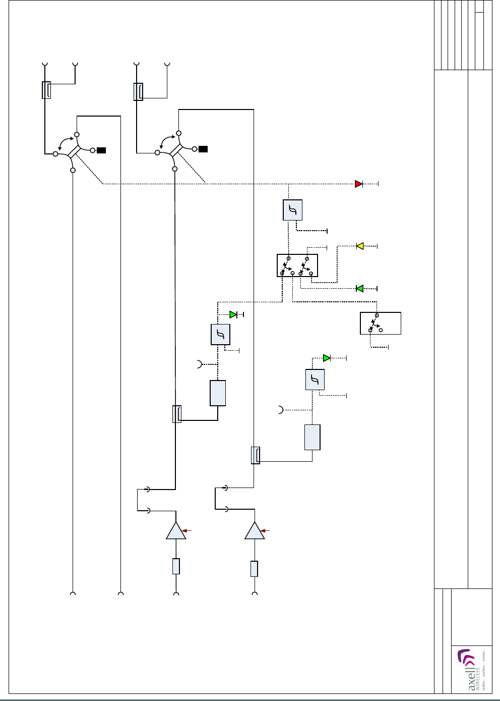
Axell Wireless Limited
Technical Literature
WMATA CRCS Redundant Antenna System
General Overview
Document Number 60-228701HBK Issue No. 3 Date 28/05/2010 Page 82 of 114
RF Failover Switch Unit 60-228905
RF Circuit Diagram
Date: 01/12/2009
Page 1 of 1
A3
Issue: 4
Drawn by: EW/AJS
Not to Scale
© AWL 2009
Aerial House
Asheridge Road
Chesham
Buckinghamshire
HP5 2QD United Kingdom
Telephone: +44 (0) 1494 777000
Facsimile: +44 (0) 1494 777002
E-Mail: info@axellwireless.com
www.axellwireless.com
30 dB
30 dB
RF
Detector
12-030301
12-030301
90-852320
20 dB
17-019805
17-019805
93-930007
0 V
0 V
Relays Shown when level
from Fiber Optic Receiver
Path 1 is above Threshold
Rx2
is Active
Auto / Manual Schmidt with
Hysteresis
12 V
520 mA
12 V
520 mA
D/L Path 1, Primary D/L I/P
from Dual Fibre Optic Unit
60-228703
2 X 96-900045
+12V
Manual
on
Path 1a
Path 1 Mon
0 V
RX1 / RX2
0 V
Auto
on
+12V
Relay
0V
0 V
0 V
0 V
Rx1
is Active
Schmidt with
Hysteresis
Schmidt with
Hysteresis
Path 2 Mon
Path 1b
Path 2a Path 2b
Mon DL
U/L I/P from
5 U/L Combiner
Unit 60-228907
Mon UL
90-852330
30 dB
93-930007
90-852320
20 dB
90-852330
30 dB
8 dB
93-000065
8 dB
93-000065
1
2
3
4
1
2
3
4
RF
Detector
D/L Path 2, Redundant D/L I/P
from Dual Fibre Optic Unit
60-228703
U/L Path 1, Primary U/L O/P
to Dual Fibre Optic Unit
60-228703
U/L Path 2, Redundant U/L O/P
to Dual Fibre Optic Unit
60-228703 D/L O/P to
CRCS Donor Unit
5.12.3. RF Failover Switch Unit 60-228905 System Diagram
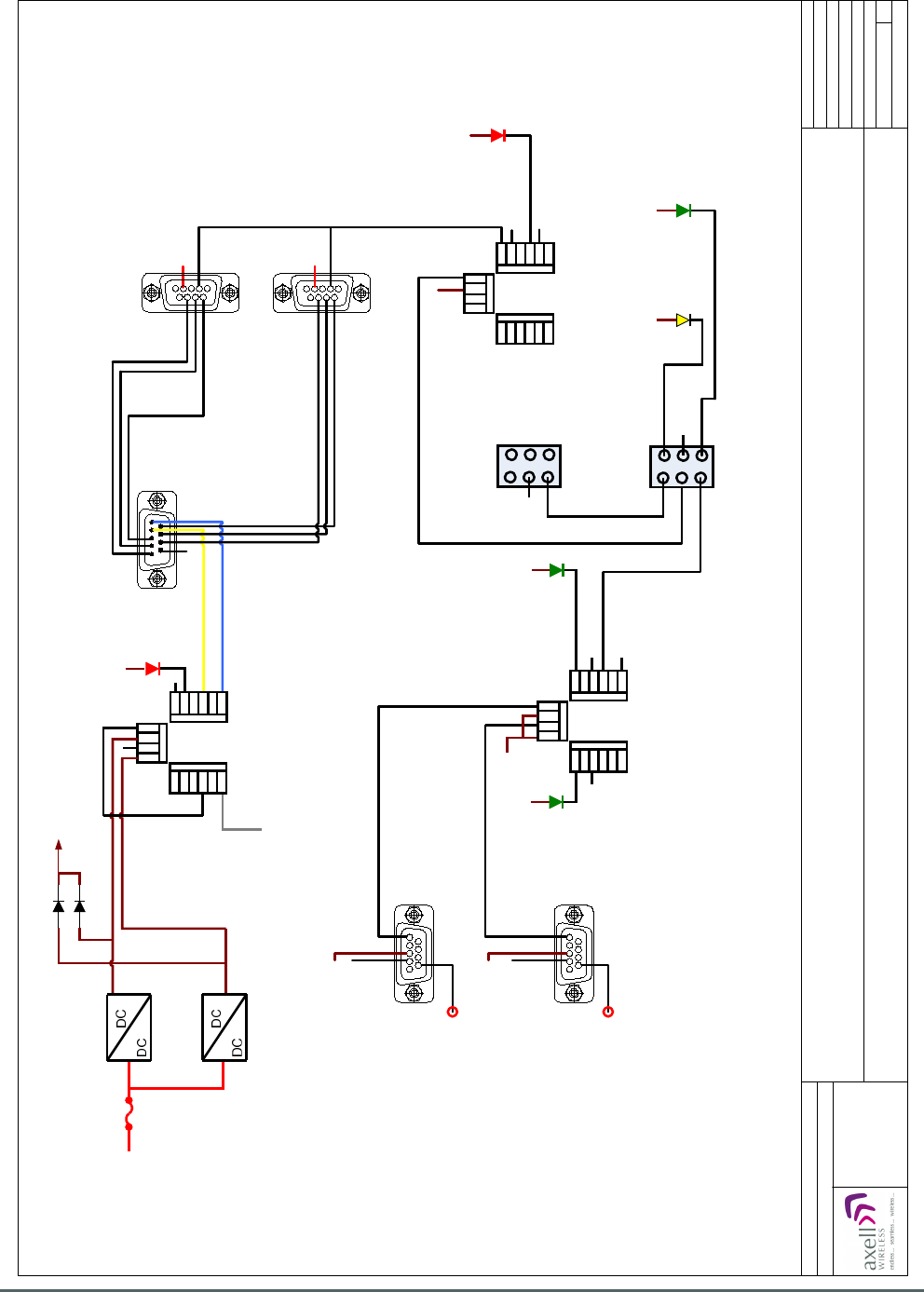
Axell Wireless Limited
Technical Literature
WMATA CRCS Redundant Antenna System
General Overview
Document Number 60-228701HBK Issue No. 3 Date 28/05/2010 Page 83 of 114
1
9
0V
AGC 1
ALARM
VOLT FREE
CONTACT
1
9
1
9
0V
AGC 2 0V
RELAY
Auto On
Auto / Manual
0V
Manual Rx1/ Rx2
0V
2 x 96-920002
0V
Rx2 is Active
0V
0V
0V
+24 V
2x96-900045
20-001601
ALARM LED
NO
NC
COM
NO
NC
COM
+12 V
0V
LOOP Gray
+12V 3A
96-200024
DC Converter 1
60W
96-110001
96-110013
3.15 A
2 x 94-100003
+12V
0V
96-200024
DC Converter 2
60W
17-019805
17-019805
+12V
+12V
+12V
+12V
+12V
+12V
+12V
+12V+12V
1
9
1
9
NO
NC
COM
NO
NC
COM
+12 V
0 V
0 V
Yellow
Blue
20-001601
NO
NC
COM
NO
NC
COM
NO
NC
COM
NO
NC
COM
+12 V
+12 V
0 V
0 V
20-001601
NO
NC
COM
NO
NC
COM
NO
NC
COM
NO
NC
COM
+12 V
+12 V
0 V
0 V
0V
Path 1 Mon
(Primary D/L)
Path 2 Mon
(Redundant D/L)
COM
NO NC
+24 V
RF Failover Switch Unit 60-228905
Alarm Wiring Diagram
Date: 01/12/2009
Page 1 of 1
A3
Issue: 4
Drawn by: EW/AJS
Not to Scale
© AWL 2009
Aerial House
Asheridge Road
Chesham
Buckinghamshire
HP5 2QD United Kingdom
Telephone: +44 (0) 1494 777000
Facsimile: +44 (0) 1494 777002
E-Mail: info@axellwireless.com
www.axellwireless.com
Manual On
Rx1 is Active
5.12.4. RF Failover Switch Unit 60-228905 Alarm Wiring Diagram
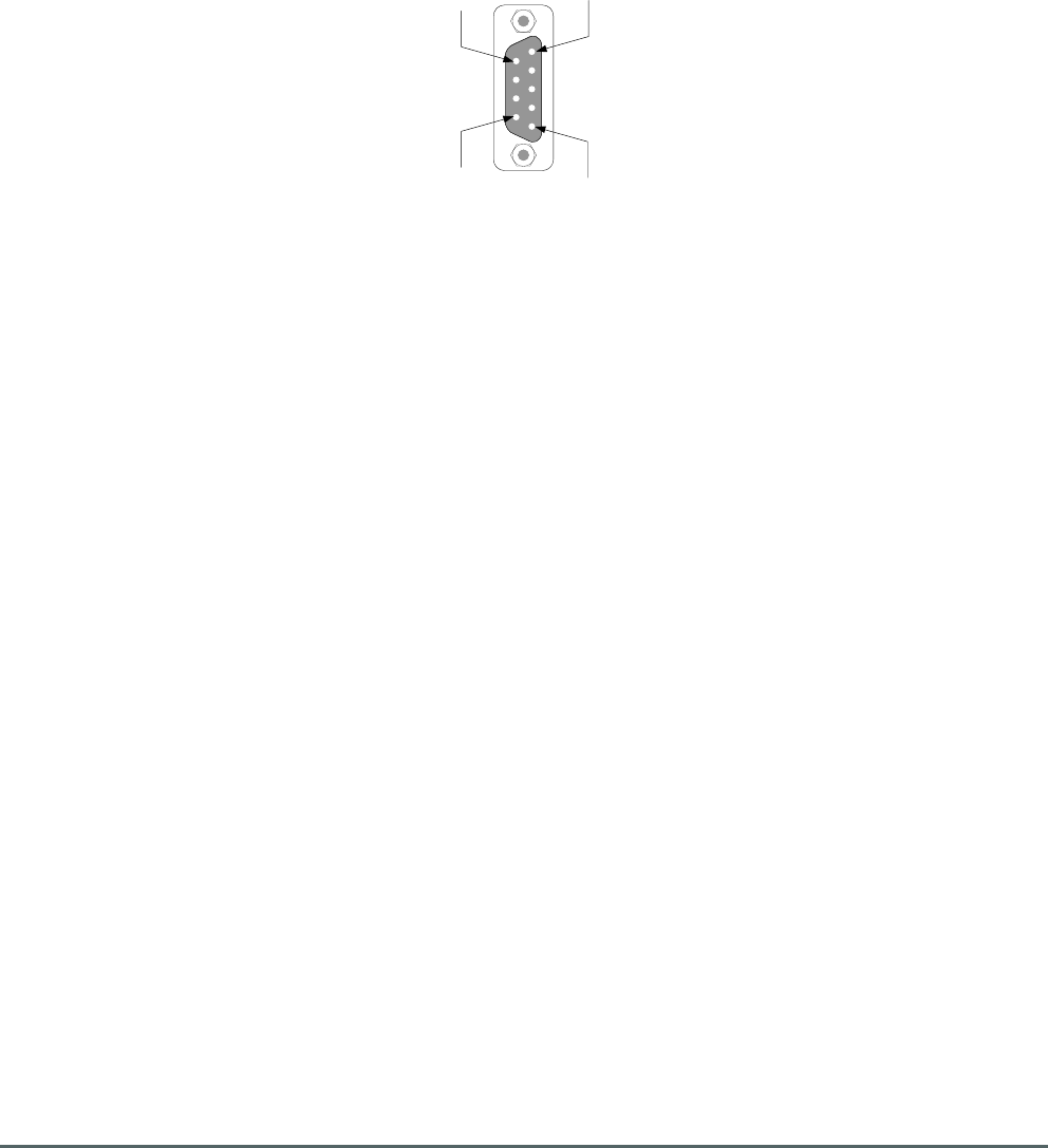
Axell Wireless Limited
Technical Literature
WMATA CRCS Redundant Antenna System
General Overview
Document Number 60-228701HBK Issue No. 3 Date 28/05/2010 Page 84 of 114
Pin 9
Pin 6
Pin 5
Pin 1
5.12.4.1. RF Failover Switch Unit 60-228905 Alarm Outputs
Front panel 9 pin “D” panel plug “ALARM”, local alarm output to Krone terminal block “A” on rack (see
section 5.5.)
Dry Contact Outputs (Closed = Normal / Open = Alarm)
Summary output PSU modules Pins 1 & 2
Uplink path relay Pins 3, 4 & 5
Downlink path relay Pins 6, 7 & 8
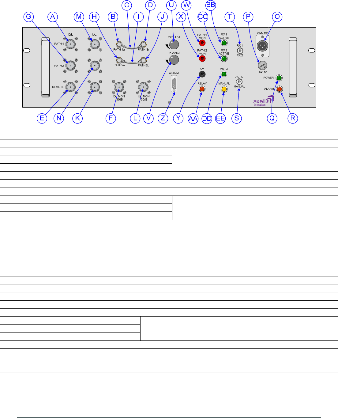
Axell Wireless Limited
Technical Literature
WMATA CRCS Redundant Antenna System
General Overview
Document Number 60-228701HBK Issue No. 3 Date 28/05/2010 Page 85 of 114
5.12.5. RF Failover Switch Unit 60-228905 Front View
A N type port “PATH 1 D/L”, Primary D/L I/P from Jackson Graham Building CRAS System
B SMA port “PATH 1a” Primary D/L O/P Allows signal path monitoring between
ports “A” and “B” and ports “D” and “E”
C UT141 link between ports annotated “B” and “D”
D SMA port “PATH 1b” Primary D/L I/P
E N type port “REMOTE D/L”, Primary D/L O/P to CRCS donor unit
F N type port “D/L MON -30dB”, test/monitor port coupled from Primary D/L O/P to CRCS donor unit
G N type port “PATH 2 D/L”, Redundant D/L I/P from Carmen Turner Facility CRAS System
H SMA port “PATH 2a” Redundant D/L O/P Allows signal path monitoring between
ports “G” and “H” and ports “J” and “E”
when secondary RF path is switched in
I UT141 link between ports annotated “H” and “J”
J SMA port “PATH 2b” Redundant D/L I/P
K N type port “REMOTE U/L”, combined U/L I/P from 5 U/L Combiner Unit 60-228907
L N type port “U/L MON -30dB”, test/monitor port coupled from combined U/L I/P from 60-228907
M N type port “PATH 1 U/L”, Primary U/L O/P to Jackson Graham Building CRAS System
N N type port “PATH 2 U/L”, Redundant U/L O/P to Carmen Turner Facility CRAS System
O 24V DC input from PSU module 96-300091 in PSU shelf 96-300090
P 3.15A fuse for DC input
Q Green LED “POWER”, illuminated during normal operation
R Red LED “ALARM”, Illuminated during alarm condition
S Toggle switch “AUTO MANUAL”, switches out signal sensing to allow manual choice of D/L path
T Toggle switch “RX 1 RX 2”, for manual switching between Main and Standby Downlink paths
U Signal threshold adjust for Primary Downlink path
V Signal threshold adjust for Redundant Downlink path
W 4mm banana socket “PATH 1 MON”
Allows DC monitoring of RF path signal strength X 4mm banana socket “PATH 2 MON”
Y 4mm banana socket “0V”
Z 9 way “D” panel plug “ALARM”, local alarm summary output to Krone terminal block on rack
AA
Red LED “RELAY”, illuminated when relay is switched from Primary to Redundant D/L path
BB
Green LED “RX 1 ACTIVE”, illuminated when Primary Downlink path is active
CC
Green LED “RX 2 ACTIVE”, illuminated when Redundant Downlink path is active
DD
Green LED “AUTO”, illuminated when signal sensing is switched in to monitor D/L path signal strength
EE
Yell
ow LED “MANUAL”, illuminated when signal sensing is switched out to allow manual choice of D/L path

Axell Wireless Limited
Technical Literature
WMATA CRCS Redundant Antenna System
General Overview
Document Number 60-228701HBK Issue No. 3 Date 28/05/2010 Page 86 of 114
5.12.6. RF Failover Switch Unit 60-228905 Rear View
A Earthing connection

Axell Wireless Limited
Technical Literature
WMATA CRCS Redundant Antenna System
General Overview
Document Number 60-228701HBK Issue No. 3 Date 28/05/2010 Page 87 of 114
5.13. Combiner Unit 60-228906
Combiner Unit 60-228906 is built onto a 2U, 19” rack mount front panel and combines the Uplink output
paths from the seven, 16 Ch. DSP U/L Squelch Gates 60-228904 mounted in the front of Rack 2 and
passes the combined Uplink signal to Combiner Unit 60-228907 mounted in the front of Rack 1.
5.13.1. Combiner Unit 60-228906 List of Major Sub-Components
Component
Part
Part Description Qty Per
Assembly
06-001901 8 Way Hybrid Splitter/Combiner 1
93-930008 2W Load Termination 1
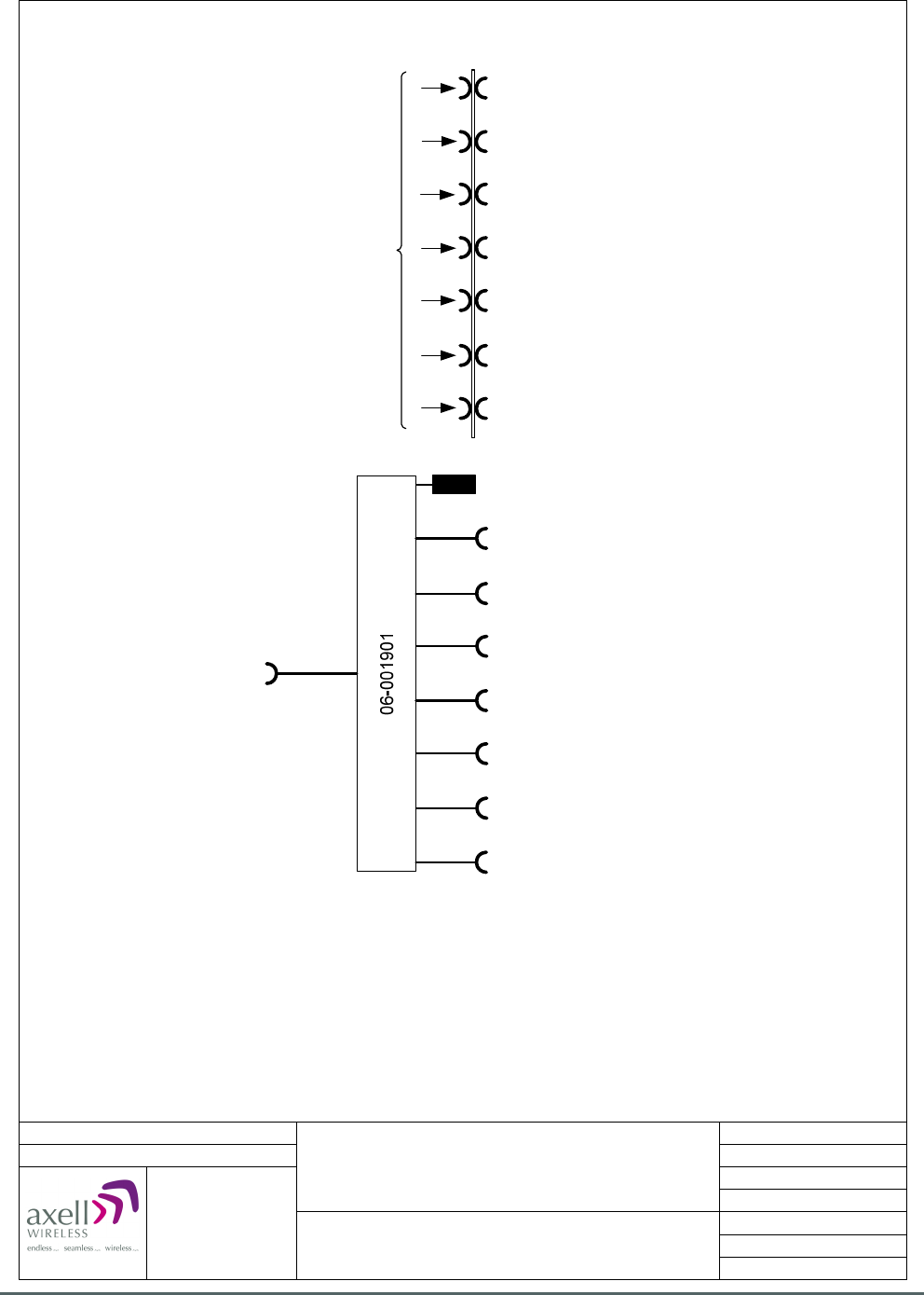
Axell Wireless Limited
Technical Literature
WMATA CRCS Redundant Antenna System
General Overview
Document Number 60-228701HBK Issue No. 3 Date 28/05/2010 Page 88 of 114
Date: 07/12/2009
© AWL 2009
Page 1 of 1
A4
Issue: 1
Drawn by: EW/AJS
Not to Scale
Aerial House
Asheridge Road
Chesham
Buckinghamshire
HP5 2QD United Kingdom
Telephone: +44 (0) 1494 777000
Facsimile: +44 (0) 1494 777002
E-Mail: info@axellwireless.com
www.axellwireless.com
Combiner Unit 60-22906
System Diagram
Rack 2, Front
93-930008
Patch-panel
U/L inputs from CRCS Donor Unit
for 16 Ch. DSP U/L Squelch Gates 1-7
(connections on rear of front panel)
Combined U/L output to
Combiner Unit 60-228907
U/L O/P to 16 Ch. DSP U/L Squelch Gate 3
U/L O/P to 16 Ch. DSP U/L Squelch Gate 4
U/L O/P to 16 Ch. DSP U/L Squelch Gate 5
U/L O/P to 16 Ch. DSP U/L Squelch Gate 6
U/L O/P to 16 Ch. DSP U/L Squelch Gate 7
U/L I/P from 16 Ch. DSP U/L Squelch Gate 1
U/L I/P from 16 Ch. DSP U/L Squelch Gate 2
U/L I/P from 16 Ch. DSP U/L Squelch Gate 3
U/L I/P from 16 Ch. DSP U/L Squelch Gate 4
U/L I/P from 16 Ch. DSP U/L Squelch Gate 5
U/L I/P from 16 Ch. DSP U/L Squelch Gate 6
U/L I/P from 16 Ch. DSP U/L Squelch Gate 7
U/L O/P to 16 Ch. DSP U/L Squelch Gate 1
U/L O/P to 16 Ch. DSP U/L Squelch Gate 2
5.13.2. Combiner Unit 60-228906 System Diagram
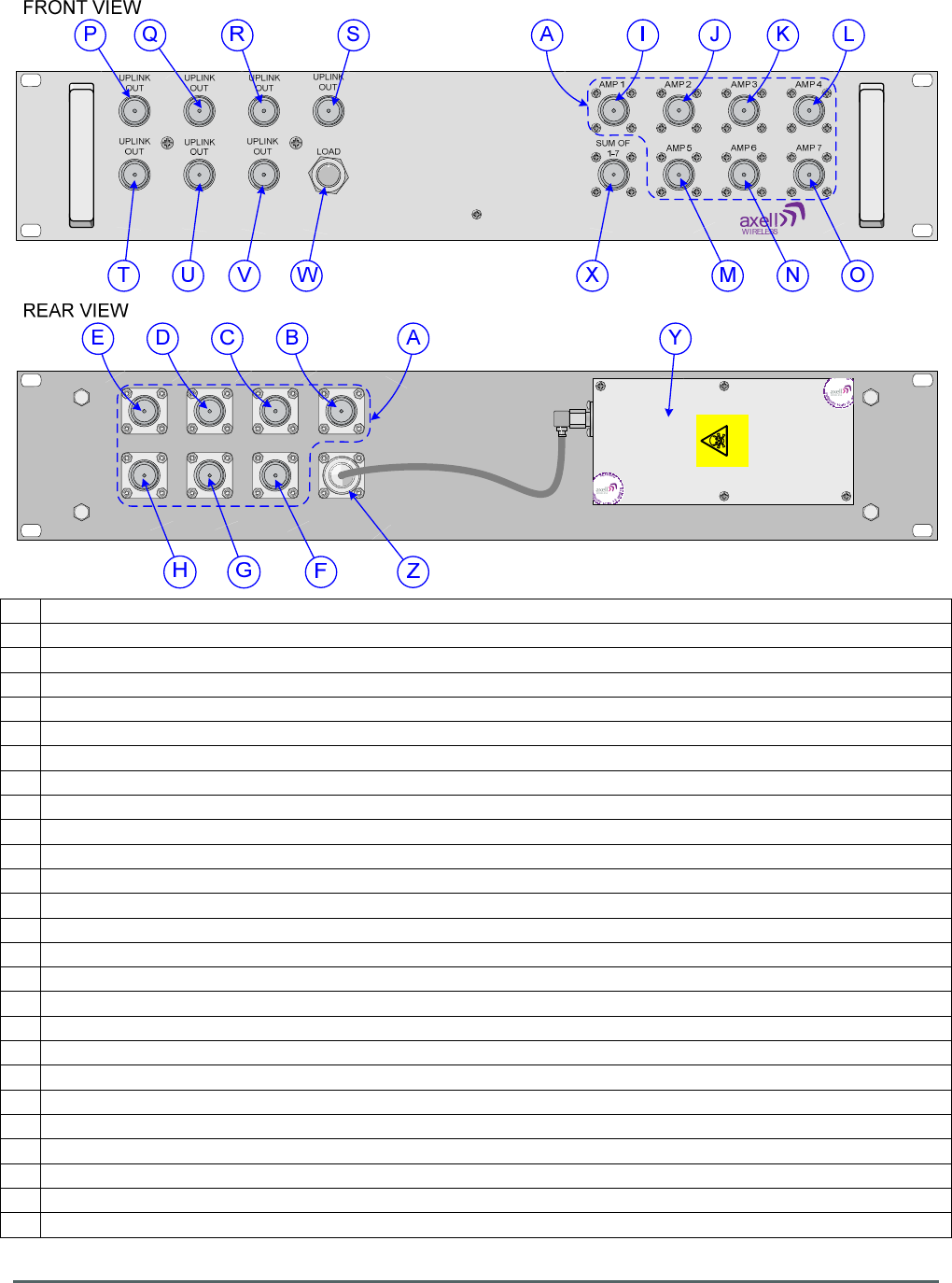
Axell Wireless Limited
Technical Literature
WMATA CRCS Redundant Antenna System
General Overview
Document Number 60-228701HBK Issue No. 3 Date 28/05/2010 Page 89 of 114
Danger
Beryllium oxide
5.13.3. Combiner Unit 60-228906 Front and Rear Views
A Patch-panel for U/L I/Ps from CRCS donor unit and O/Ps to 16 Ch. DSP U/L Squelch Gates 1 to 7
B Uplink input for 16 Ch. DSP U/L Squelch Gate No. 1 from CRCS donor unit
C Uplink input for 16 Ch. DSP U/L Squelch Gate No. 2 from CRCS donor unit
D Uplink input for 16 Ch. DSP U/L Squelch Gate No. 3 from CRCS donor unit
E Uplink input for 16 Ch. DSP U/L Squelch Gate No. 4 from CRCS donor unit
F Uplink input for 16 Ch. DSP U/L Squelch Gate No. 5 from CRCS donor unit
G Uplink input for 16 Ch. DSP U/L Squelch Gate No. 6 from CRCS donor unit
H Uplink input for 16 Ch. DSP U/L Squelch Gate No. 7 from CRCS donor unit
I N type port “AMP 1, U/L O/P to 16 Ch. DSP U/L Squelch Gate No. 1
J N type port “AMP 2, U/L O/P to 16 Ch. DSP U/L Squelch Gate No. 2
K N type port “AMP 3, U/L O/P to 16 Ch. DSP U/L Squelch Gate No. 3
L N type port “AMP 4, U/L O/P to 16 Ch. DSP U/L Squelch Gate No. 4
M N type port “AMP 5, U/L O/P to 16 Ch. DSP U/L Squelch Gate No. 5
N N type port “AMP 6, U/L O/P to 16 Ch. DSP U/L Squelch Gate No. 6
O N type port “AMP 7, U/L O/P to 16 Ch. DSP U/L Squelch Gate No. 7
P N type port “UPLINK OUT”, U/L input from 16 Ch. DSP U/L Squelch Gate No. 1
Q N type port “UPLINK OUT”, U/L input from 16 Ch. DSP U/L Squelch Gate No. 2
R N type port “UPLINK OUT”, U/L input from 16 Ch. DSP U/L Squelch Gate No. 3
S N type port “UPLINK OUT”, U/L input from 16 Ch. DSP U/L Squelch Gate No. 4
T N type port “UPLINK OUT”, U/L input from 16 Ch. DSP U/L Squelch Gate No. 5
U N type port “UPLINK OUT”, U/L input from 16 Ch. DSP U/L Squelch Gate No. 6
V N type port “UPLINK OUT”, U/L input from 16 Ch. DSP U/L Squelch Gate No. 7
W
Unused U/L input terminated with Load Termination 93-930008
X N type port “SUM OF 1-7”, combined U/L O/P from 16 Ch. DSP U/L Squelch Gates No. 1 to 7
Y 8 Way Hybrid Splitter/Combiner 06-001901 (Combining)
Z Rear of N type port (X) “SUM OF 1-7”

Axell Wireless Limited
Technical Literature
WMATA CRCS Redundant Antenna System
General Overview
Document Number 60-228701HBK Issue No. 3 Date 28/05/2010 Page 90 of 114
5.14. Combiner Unit 60-228908
Combiner Unit 60-228908 is built onto a 2U, 19” rack mount front panel and combines the Uplink output
paths from the seven, 16 Ch. DSP U/L Squelch Gates 60-228904 mounted in the rear of Rack 2 and passes
the combined Uplink signal to Combiner Unit 60-228907 mounted in the front of Rack 1.
5.14.1. Combiner Unit 60-228908 List of Major Sub-Components
Component
Part
Part Description Qty Per
Assembly
06-001901 8 Way Hybrid Splitter/Combiner 1
93-930008 2W Load Termination 1
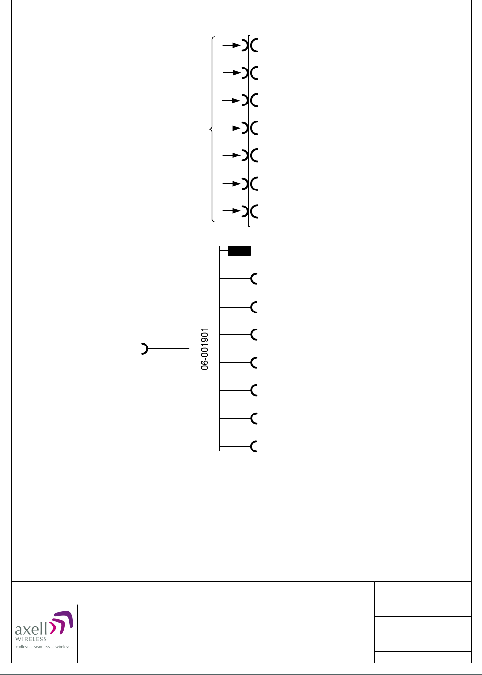
Axell Wireless Limited
Technical Literature
WMATA CRCS Redundant Antenna System
General Overview
Document Number 60-228701HBK Issue No. 3 Date 28/05/2010 Page 91 of 114
Date: 07/12/2009
© AWL 2009
Page 1 of 1
A4
Issue: 1
Drawn by: EW/AJS
Not to Scale
Aerial House
Asheridge Road
Chesham
Buckinghamshire
HP5 2QD United Kingdom
Telephone: +44 (0) 1494 777000
Facsimile: +44 (0) 1494 777002
E-Mail: info@axellwireless.com
www.axellwireless.com
Combiner Unit 60-22908
System Diagram
Rack 2, Rear
93-930008
Patch-panel
U/L inputs from CRCS Donor Unit
for 16 Ch. DSP U/L Squelch Gates 8-14
(connections on rear of front panel)
Combined U/L output to
Combiner Unit 60-228907
U/L O/P to 16 Ch. DSP U/L Squelch Gate 10
U/L O/P to 16 Ch. DSP U/L Squelch Gate 11
U/L O/P to 16 Ch. DSP U/L Squelch Gate 12
U/L O/P to 16 Ch. DSP U/L Squelch Gate 13
U/L O/P to 16 Ch. DSP U/L Squelch Gate 14
U/L I/P from 16 Ch. DSP U/L Squelch Gate 8
U/L I/P from 16 Ch. DSP U/L Squelch Gate 9
U/L I/P from 16 Ch. DSP U/L Squelch Gate 10
U/L I/P from 16 Ch. DSP U/L Squelch Gate 11
U/L I/P from 16 Ch. DSP U/L Squelch Gate 12
U/L I/P from 16 Ch. DSP U/L Squelch Gate 13
U/L I/P from 16 Ch. DSP U/L Squelch Gate 14
U/L O/P to 16 Ch. DSP U/L Squelch Gate 8
U/L O/P to 16 Ch. DSP U/L Squelch Gate 9
5.14.2. Combiner Unit 60-228908 System Diagram
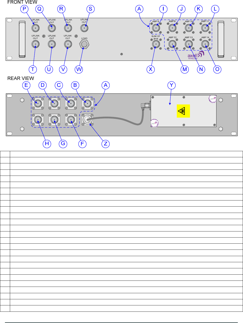
Axell Wireless Limited
Technical Literature
WMATA CRCS Redundant Antenna System
General Overview
Document Number 60-228701HBK Issue No. 3 Date 28/05/2010 Page 92 of 114
Danger
Beryllium oxide
5.14.3. Combiner Unit 60-228908 Front and Rear Views
A Patch-panel for U/L I/Ps from CRCS donor unit and O/Ps to 16 Ch. DSP U/L Squelch Gates 8 to 14
B Uplink input for 16 Ch. DSP U/L Squelch Gate No. 8 from CRCS donor unit
C Uplink input for 16 Ch. DSP U/L Squelch Gate No. 9 from CRCS donor unit
D Uplink input for 16 Ch. DSP U/L Squelch Gate No. 10 from CRCS donor unit
E Uplink input for 16 Ch. DSP U/L Squelch Gate No. 11 from CRCS donor unit
F Uplink input for 16 Ch. DSP U/L Squelch Gate No. 12 from CRCS donor unit
G Uplink input for 16 Ch. DSP U/L Squelch Gate No. 13 from CRCS donor unit
H Uplink input for 16 Ch. DSP U/L Squelch Gate No. 14 from CRCS donor unit
I N type port “AMP 8, U/L O/P to 16 Ch. DSP U/L Squelch Gate No. 8
J N type port “AMP 9, U/L O/P to 16 Ch. DSP U/L Squelch Gate No. 9
K N type port “AMP 10, U/L O/P to 16 Ch. DSP U/L Squelch Gate No. 10
L N type port “AMP 11, U/L O/P to 16 Ch. DSP U/L Squelch Gate No. 11
M N type port “AMP 12, U/L O/P to 16 Ch. DSP U/L Squelch Gate No. 12
N N type port “AMP 13, U/L O/P to 16 Ch. DSP U/L Squelch Gate No. 13
O N type port “AMP 14, U/L O/P to 16 Ch. DSP U/L Squelch Gate No. 14
P N type port “UPLINK OUT”, U/L input from 16 Ch. DSP U/L Squelch Gate No. 8
Q N type port “UPLINK OUT”, U/L input from 16 Ch. DSP U/L Squelch Gate No. 9
R N type port “UPLINK OUT”, U/L input from 16 Ch. DSP U/L Squelch Gate No. 10
S N type port “UPLINK OUT”, U/L input from 16 Ch. DSP U/L Squelch Gate No. 11
T N type port “UPLINK OUT”, U/L input from 16 Ch. DSP U/L Squelch Gate No. 12
U N type port “UPLINK OUT”, U/L input from 16 Ch. DSP U/L Squelch Gate No. 13
V N type port “UPLINK OUT”, U/L input from 16 Ch. DSP U/L Squelch Gate No. 14
W
Unused U/L input terminated with Load Termination 93-930008
X N type port “SUM OF 8-14”, combined U/L O/P from 16 Ch. DSP U/L Squelch Gates No. 8 to 14
Y 8 Way Hybrid Splitter/Combiner 06-001901 (Combining)
Z Rear of N type port (X) “SUM OF 8-14”

Axell Wireless Limited
Technical Literature
WMATA CRCS Redundant Antenna System
General Overview
Document Number 60-228701HBK Issue No. 3 Date 28/05/2010 Page 93 of 114
5.15. Combiner Unit 60-228909
Combiner Unit 60-228909 is built onto a 2U, 19” rack mount front panel and combines the Uplink output
paths from the seven, 16 Ch. DSP U/L Squelch Gates 60-228904 mounted in the rear of Rack 1 and passes
the combined Uplink signal to Combiner Unit 60-228907 mounted in the front of Rack 1.
5.15.1. Combiner Unit 60-228909 List of Major Sub-Components
Component
Part
Part Description Qty Per
Assembly
06-001901 8 Way Hybrid Splitter/Combiner 1
93-930008 2W Load Termination 1
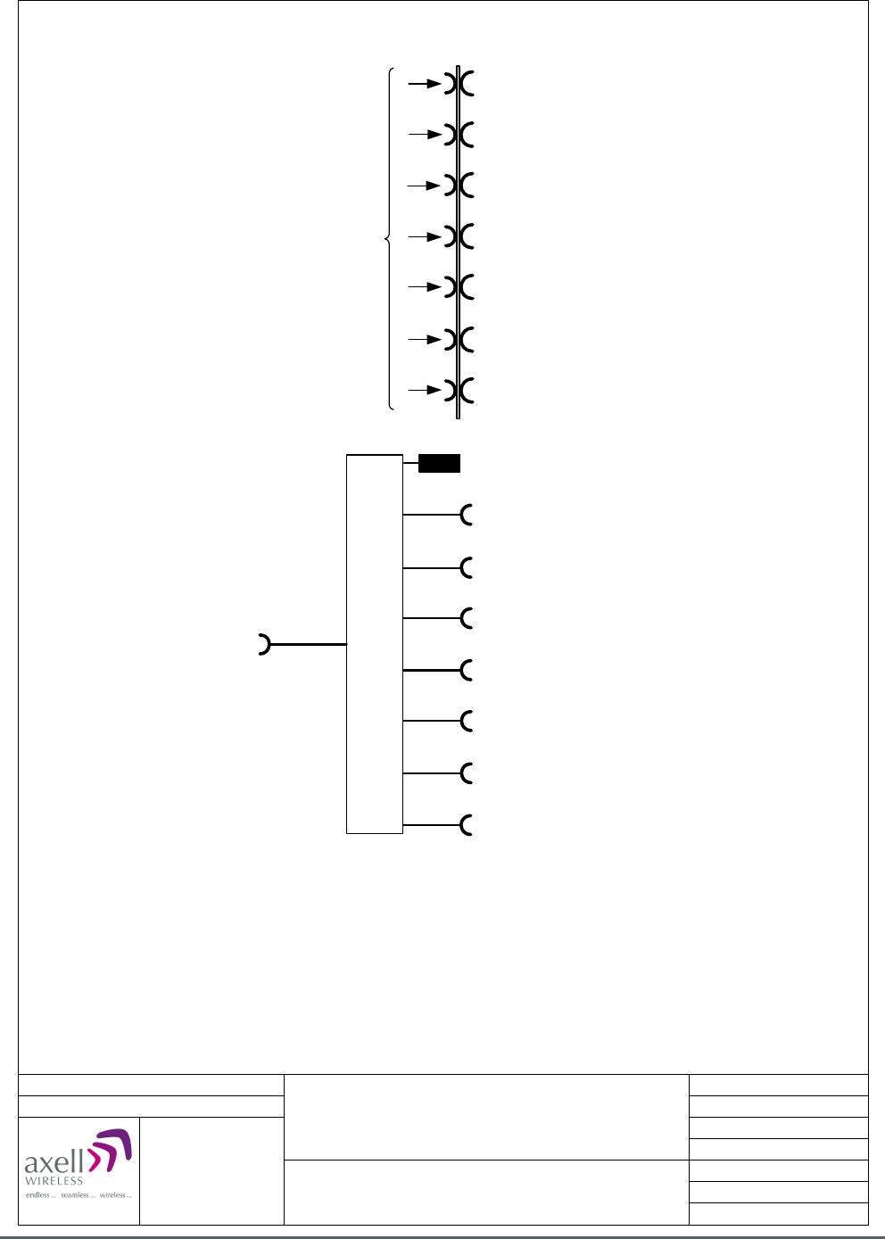
Axell Wireless Limited
Technical Literature
WMATA CRCS Redundant Antenna System
General Overview
Document Number 60-228701HBK Issue No. 3 Date 28/05/2010 Page 94 of 114
Date: 07/12/2009
© AWL 2009
Page 1 of 1
A4
Issue: 1
Drawn by: EW/AJS
Not to Scale
Aerial House
Asheridge Road
Chesham
Buckinghamshire
HP5 2QD United Kingdom
Telephone: +44 (0) 1494 777000
Facsimile: +44 (0) 1494 777002
E-Mail: info@axellwireless.com
www.axellwireless.com
Combiner Unit 60-22908
System Diagram
Rack 2, Rear
06-001901
93-930008
Patch-panel
U/L inputs from CRCS Donor Unit
for 16 Ch. DSP U/L Squelch Gates 8-14
(connections on rear of front panel)
Combined U/L output to
Combiner Unit 60-228907
U/L O/P to 16 Ch. DSP U/L Squelch Gate 10
U/L O/P to 16 Ch. DSP U/L Squelch Gate 11
U/L O/P to 16 Ch. DSP U/L Squelch Gate 12
U/L O/P to 16 Ch. DSP U/L Squelch Gate 13
U/L O/P to 16 Ch. DSP U/L Squelch Gate 14
U/L I/P from 16 Ch. DSP U/L Squelch Gate 8
U/L I/P from 16 Ch. DSP U/L Squelch Gate 9
U/L I/P from 16 Ch. DSP U/L Squelch Gate 10
U/L I/P from 16 Ch. DSP U/L Squelch Gate 11
U/L I/P from 16 Ch. DSP U/L Squelch Gate 12
U/L I/P from 16 Ch. DSP U/L Squelch Gate 13
U/L I/P from 16 Ch. DSP U/L Squelch Gate 14
U/L O/P to 16 Ch. DSP U/L Squelch Gate 8
U/L O/P to 16 Ch. DSP U/L Squelch Gate 9
5.15.2. Combiner Unit 60-228909 System Diagram
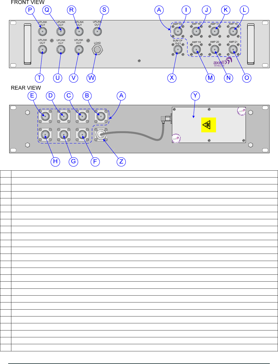
Axell Wireless Limited
Technical Literature
WMATA CRCS Redundant Antenna System
General Overview
Document Number 60-228701HBK Issue No. 3 Date 28/05/2010 Page 95 of 114
Danger
Beryllium oxide
5.15.3. Combiner Unit 60-228909 Front and Rear Views
A Patch-panel for U/L I/Ps from CRCS donor unit and O/Ps to 16 Ch. DSP U/L Squelch Gates 15 to 21
B Uplink input for 16 Ch. DSP U/L Squelch Gate No. 15 from CRCS donor unit
C Uplink input for 16 Ch. DSP U/L Squelch Gate No. 16 from CRCS donor unit
D Uplink input for 16 Ch. DSP U/L Squelch Gate No. 17 from CRCS donor unit
E Uplink input for 16 Ch. DSP U/L Squelch Gate No. 18 from CRCS donor unit
F Uplink input for 16 Ch. DSP U/L Squelch Gate No. 19 from CRCS donor unit
G Uplink input for 16 Ch. DSP U/L Squelch Gate No. 20 from CRCS donor unit
H Uplink input for 16 Ch. DSP U/L Squelch Gate No. 21 from CRCS donor unit
I N type port “AMP 15”, U/L O/P to 16 Ch. DSP U/L Squelch Gate No. 15
J N type port “AMP 16”, U/L O/P to 16 Ch. DSP U/L Squelch Gate No. 16
K N type port “AMP 17”, U/L O/P to 16 Ch. DSP U/L Squelch Gate No. 17
L N type port “AMP 18”, U/L O/P to 16 Ch. DSP U/L Squelch Gate No. 18
M N type port “AMP 19”, U/L O/P to 16 Ch. DSP U/L Squelch Gate No. 19
N N type port “AMP 20”, U/L O/P to 16 Ch. DSP U/L Squelch Gate No. 20
O N type port “AMP 21”, U/L O/P to 16 Ch. DSP U/L Squelch Gate No. 21
P N type port “UPLINK OUT”, U/L input from 16 Ch. DSP U/L Squelch Gate No. 15
Q N type port “UPLINK OUT”, U/L input from 16 Ch. DSP U/L Squelch Gate No. 16
R N type port “UPLINK OUT”, U/L input from 16 Ch. DSP U/L Squelch Gate No. 17
S N type port “UPLINK OUT”, U/L input from 16 Ch. DSP U/L Squelch Gate No. 18
T N type port “UPLINK OUT”, U/L input from 16 Ch. DSP U/L Squelch Gate No. 19
U N type port “UPLINK OUT”, U/L input from 16 Ch. DSP U/L Squelch Gate No. 20
V N type port “UPLINK OUT”, U/L input from 16 Ch. DSP U/L Squelch Gate No. 21
W
Unused U/L input terminated with Load Termination 93-930008
X N type port “SUM OF 15-21”,combined U/L O/P from 16 Ch. DSP U/L Squelch Gates No. 15 to 21
Y 8 Way Hybrid Splitter/Combiner 06-001901 (Combining)
Z Rear of N type port (X) “SUM OF 15-21”

Axell Wireless Limited
Technical Literature
WMATA CRCS Redundant Antenna System
General Overview
Document Number 60-228701HBK Issue No. 3 Date 28/05/2010 Page 96 of 114
5.16. Combiner Unit 60-228907
Combiner Unit 60-228907 is built onto a 2U, 19” rack mount front panel and combines the Uplink output
paths from Combiner units 60-228906. 60-228908 & 60-228909 with the Uplink paths from the five, 16 Ch.
DSP U/L Squelch Gates 60-228904 mounted in the front of Rack 1 and passes the combined Uplink signal
to RF Failover Switch Unit 60-228905.
5.16.1. Combiner Unit 60-228907 List of Major Sub-Components
Component
Part
Part Description Qty Per
Assembly
06-001801 4 Way Hybrid Splitter/Combiner 1
06-001901 8 Way Hybrid Splitter/Combiner 1
93-930008 2W Load Termination 3
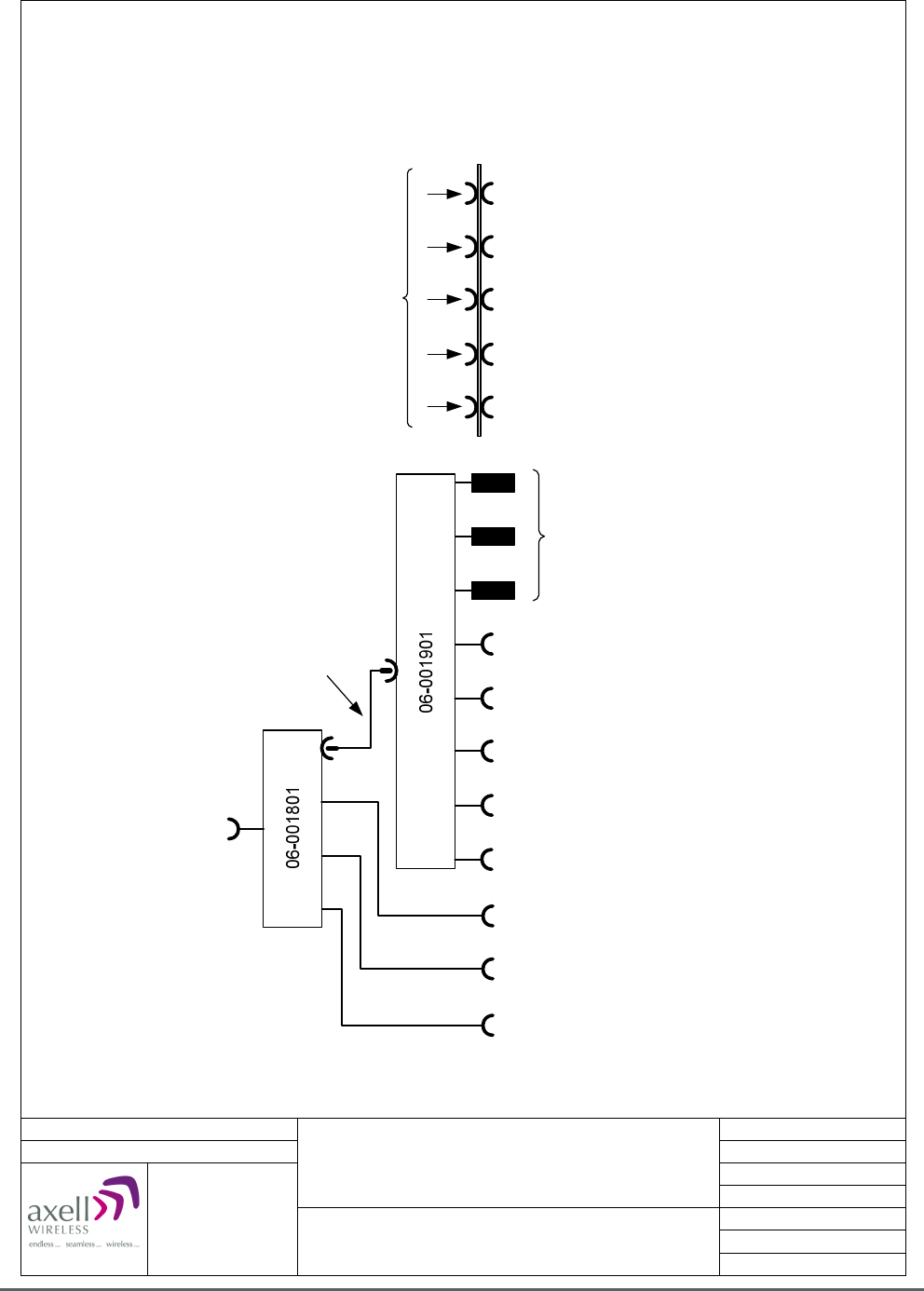
Axell Wireless Limited
Technical Literature
WMATA CRCS Redundant Antenna System
General Overview
Document Number 60-228701HBK Issue No. 3 Date 28/05/2010 Page 97 of 114
Date: 02/12/2009
© AWL 2009
Page 1 of 1
A4
Issue: 1
Drawn by: EW/AJS
Not to Scale
Aerial House
Asheridge Road
Chesham
Buckinghamshire
HP5 2QD United Kingdom
Telephone: +44 (0) 1494 777000
Facsimile: +44 (0) 1494 777002
E-Mail: info@axellwireless.com
www.axellwireless.com
Combiner Unit 60-228907
System Diagram
Rack 1, Front
3 x 93-930008
Combined U/L I/P from Combiner Unit 60-228906
16 Ch. DSP U/L Squelch Gates 1 to 7
Patch-panel
U/L inputs from CRCS Donor Unit
for 16 Ch. DSP U/L Squelch Gates 22-26
(connections on rear of front panel)
RG223 jump lead,
connectors on front panel
U/L output to
RF Failover Switch Unit
60-228905
U/L O/P to 16 Ch. DSP U/L Squelch Gate 22
U/L O/P to 16 Ch. DSP U/L Squelch Gate 23
U/L O/P to 16 Ch. DSP U/L Squelch Gate 24
U/L O/P to 16 Ch. DSP U/L Squelch Gate 25
U/L O/P to 16 Ch. DSP U/L Squelch Gate 26
U/L I/P from 16 Ch. DSP U/L Squelch Gate 22
U/L I/P from 16 Ch. DSP U/L Squelch Gate 23
U/L I/P from 16 Ch. DSP U/L Squelch Gate 24
U/L I/P from 16 Ch. DSP U/L Squelch Gate 25
U/L I/P from 16 Ch. DSP U/L Squelch Gate 26
Combined U/L I/P from Combiner Unit 60-228908
16 Ch. DSP U/L Squelch Gates 8 to 14
Combined U/L I/P from Combiner Unit 60-228909
16 Ch. DSP U/L Squelch Gates 15 to 21
5.16.2. Combiner Unit 60-228907 System Diagram
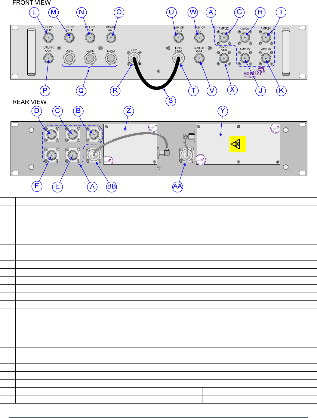
Axell Wireless Limited
Technical Literature
WMATA CRCS Redundant Antenna System
General Overview
Document Number 60-228701HBK Issue No. 3 Date 28/05/2010 Page 98 of 114
Danger
Beryllium oxide
5.16.3. Combiner Unit 60-228907 Front and Rear Views
A Patch-panel for U/L I/Ps from CRCS donor unit and O/Ps to 16 Ch. DSP U/L Squelch Gates 22 to 26
B Uplink input for 16 Ch. DSP U/L Squelch Gate No. 22 from CRCS donor unit
C Uplink input for 16 Ch. DSP U/L Squelch Gate No. 23 from CRCS donor unit
D Uplink input for 16 Ch. DSP U/L Squelch Gate No. 24 from CRCS donor unit
E Uplink input for 16 Ch. DSP U/L Squelch Gate No. 25 from CRCS donor unit
F Uplink input for 16 Ch. DSP U/L Squelch Gate No. 26 from CRCS donor unit
G N type port “AMP 22”, U/L O/P to 16 Ch. DSP U/L Squelch Gate No. 22
H N type port “AMP 23”, U/L O/P to 16 Ch. DSP U/L Squelch Gate No. 23
I N type port “AMP 24”, U/L O/P to 16 Ch. DSP U/L Squelch Gate No. 24
J N type port “AMP 25”, U/L O/P to 16 Ch. DSP U/L Squelch Gate No. 25
K N type port “AMP 26”, U/L O/P to 16 Ch. DSP U/L Squelch Gate No. 26
L N type port “UPLINK OUT”, U/L input from 16 Ch. DSP U/L Squelch Gate No. 22
M N type port “UPLINK OUT”, U/L input from 16 Ch. DSP U/L Squelch Gate No. 23
N N type port “UPLINK OUT”, U/L input from 16 Ch. DSP U/L Squelch Gate No. 24
O N type port “UPLINK OUT”, U/L input from 16 Ch. DSP U/L Squelch Gate No. 25
P N type port “UPLINK OUT”, U/L input from 16 Ch. DSP U/L Squelch Gate No. 26
Q Unused U/L inputs terminated with Load Terminations 93-930008
R N type port “LINK”, combined U/L O/P from 16 Ch. DSP U/L Squelch Gates No. 22 to 26
S RG223 jump lead
T N type port “LINK 22-26”,combined U/L I/P from 16 Ch. DSP U/L Squelch Gates No. 22 to 26
U N type port “SUM OF 15-21”, combined U/L I/P from 16 Ch. DSP U/L Squelch Gates No. 15 to 21
V N type port “SUM OF 8-14”, combined U/L I/P from 16 Ch. DSP U/L Squelch Gates No. 8 to 14
W N type port “SUM OF 1-7”,combined U/L I/P from 16 Ch. DSP U/L Squelch Gates No. 1 to 7
X N type port “SUM OF 1-26, ” combined U/L O/P to RF Failover Switch Unit 60-228905
Y 8 Way Hybrid Splitter/Combiner 06-001901 (Combining) AA
Rear of N type port (R) “LINK”
Z 4 Way Hybrid Splitter/Combiner 06-001801 (Combining) BB
Rear of N type port (X) “sum of 1-26”

Axell Wireless Limited
Technical Literature
WMATA CRCS Redundant Antenna System
General Overview
Document Number 60-228701HBK Issue No. 3 Date 28/05/2010 Page 99 of 114
5.17. 16 Ch. DSP U/L Squelch Gate 60-228904
16 Ch. DSP U/L Squelch Gate 60-228904 is built onto a 4U, 19” rack-mount case.
There are 26 DSP U/L Squelch Gate units in the Gallery Place System each one receives an Uplink input
from the existing CRCS donor unit. The purpose of the Squelch gate is to selectively filter the required
frequencies from the input broadband noise and intermodulation and to incorporate a digit squelch to the
signal. This ensures that only uplink paths with radio traffic are fed to the base station which in turn gives
over 13dB improvement in the carrier to signal noise floor.
The 60-228904 utilizes Software Defined Radio (SDR) technology to digitally process the signal to define
the required channel frequencies and bandwidth (eight channels in the Uplink band 1 path and eight in the
Uplink Band 2 path). As part of the digital signal processing function the signal amplitude is monitored to
apply squelch functionality to the signal path to attenuate unwanted noise when the input signal level is low.
The unit is pre-programmed with the 16 required uplink frequencies and channel bandwidths as indicated in
section 5.17.2., these can be modified by the use of RMC software.
The Uplink signals from the CRCS donor unit fiber optic receivers enter the Squelch Gate unit via the N type
port labeled “UPLINK IN” (annotated “A” in section 5.17.4.), the signal passes through a 3dB
Splitter/Combiner 05-002603 which splits the signal into two equal paths, each path then enters the UHF
SDR Module E921030. Path A handles frequencies in the range of 492.5MHz to 494.0MHz While Path B
handles frequencies in the range of 499.3MHz to 499.7MHz. The SDR module selectively amplifies and
down converts each band of frequencies to a VHF Intermediate Frequency which is converted from
Analogue to Digital before Digital Signal Processing to the required pass bandwidth and frequency (16
Uplink channels per Squelch Gate unit). During the digital processing, the amplitude of the required channel
is compared with a preset reference and if the signal exceeds the threshold setting, the signal is enabled to
the output. After signal processing has taken place, the signals pass through a Digital to Analogue process
before being up converted back to the original to frequency bands. The two Uplink signal paths (A & B) are
then recombined by a second 3dB Splitter/Combiner 05-002603 and the Uplink signal exits the Squelch
Gate via the N type port labeled “UPLINK OUT” (annotated “B” in section 5.17.4.)
16 Ch. DSP U/L Squelch Gate 60-228904 is powered by a 24V DC supply from the Redundant PSU
Modules 96-300091 in PSU Housing Shelf 96-300090, The 24V DC supply feeds an on-board DC/DC
converter J1421001 which steps down the 24V supply to provide 6.45v and 15v DC to power the SDR,
Controller and Ext. Alarm/battery modules within the Squelch Gate shelf.
An alarm system is fitted, the Squelch Gate shelf has an alarm output which is accessible from the terminals
on the front of the External Alarm and Battery Module J1161030 (annotated “E” in section 5.17.4.), from
where the alarm data is fed to the Krone terminal block located near the top of the rack (see section 5.10.).
The SDR controller module H561003 is used to control and supervise the SDR functionality, two ports are
provided where an operator may connect into the system, a local serial port, (a 9 way “D” panel socket
annotated “H” in section 5.17.4.) is used with a laptop PC running suitable terminal-emulation software to
interrogate and control the equipment using GET and SET commands. Alternatively the equipment can be
configured using RMC software via the RJ45 ethernet port (annotated “I” in section 5.17.4.) To ensure
synchronous communications between the SDR and the H56 controller, a high stability 10MHz reference
generator, R031002 is incorporated in the equipment backplane.

Axell Wireless Limited
Technical Literature
WMATA CRCS Redundant Antenna System
General Overview
Document Number 60-228701HBK Issue No. 3 Date 28/05/2010 Page 100 of 114
5.17.1. 16 Ch. DSP U/L Squelch Gate 60-228904
List of Major Sub-Components
Component
Part
Part Description Qty Per
Assembly
05-002603 3dB Splitter/Combiner 2
19-002202 Interconnection Assembly 1
96-110009 6.3A Fuse 1
E921030 UHF SDR Module (489.25-500.50MHz) 1
H561003 Control Module 1
J1161030 External Alarm and Battery Module 1
J1421001 DC/DC Converter 1
R031002 Reference Generator 1

Axell Wireless Limited
Technical Literature
WMATA CRCS Redundant Antenna System
General Overview
Document Number 60-228701HBK Issue No. 3 Date 28/05/2010 Page 101 of 114
5.17.2. 16 Ch. DSP U/L Squelch Gate 60-228904 Specification
SPECIFICATION PARAMETER
Uplink
Frequency Range
492.5MHz to 494.0MHz
499.3MHz to 499.7MHz
No. of Channels
16
(1)
Maximum Gain
+43 ±1dB
Passband ripple
≤ ±1.5 dB
ALC Setting All channels ON
-7.5±1dBm
ALC Dynamic Range
>30 dB
Switched attenuator
0dB to 30 dB in 2dB steps ±1dB
In Band Spurious Noise (30kHz B/W)
< -36 dBm @ max. gain
Squelch Level
-90 ±2dBm
Squelch Level
-80 ±2dBm
Squelch Level
-70 ±2dBm
General
Supply Voltage
24V DC
Current consumption
< 1.5 A
Alarm output
Summary volts free dry contact output
(Closed = Normal / Open = Alarm)
pins 7 & 8 - Alarm connector
terminal on External Alarm and
Battery Module J1161030
(1)
Uplink Channels
Channel Number Channel Frequency Channel Bandwidth
14 492.5125 MHz 12.5 kHz
13 492.5375 MHz 12.5 kHz
2 493.7875 MHz 25.0 kHz
12 493.8375 MHz 12.5 kHz
1 493.8625 MHz 12.5 kHz
11 493.8875 MHz 12.5 kHz
10 493.9125 MHz 12.5 kHz
9 493.9625 MHz 25.0 kHz
8 499.3375 MHz 25.0 kHz
3 499.4375 MHz 25.0 kHz
7 499.4875 MHz 12.5 kHz
Paging 499.5125 MHz 12.5 kHz
4 499.5375 MHz 12.5 kHz
6 499.5626 MHz 12.5 kHz
15 499.5875 MHz 12.5 kHz
5 499.6125 MHz 12.5 kHz
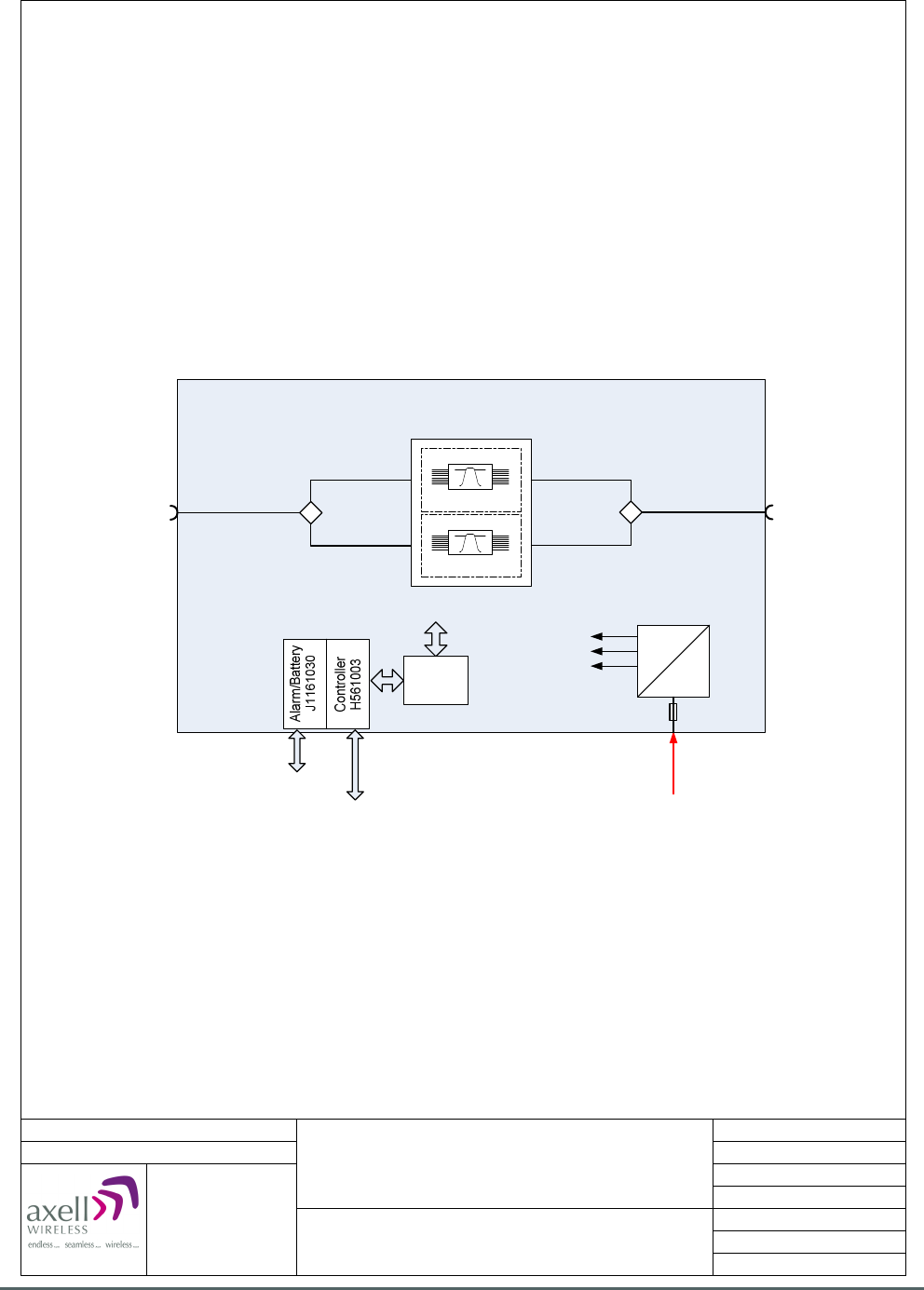
Axell Wireless Limited
Technical Literature
WMATA CRCS Redundant Antenna System
General Overview
Document Number 60-228701HBK Issue No. 3 Date 28/05/2010 Page 102 of 114
Date: 10/12/2009
© AWL 2009
Aerial House
Asheridge Road
Chesham
Buckinghamshire
HP5 2QD United Kingdom
Telephone: +44 (0) 1494 777000
Facsimile: +44 (0) 1494 777002
E-Mail: info@axellwireless.com
www.axellwireless.com
16 Ch. DSP U/L Squelch Gate
60-228904
System Diagram
UPLINK RF INUPLINK RF OUT
+24 VDC
J142001
Alarm
E921030
TETRA SDR MODULE
489,25 - 500,50 MHz
19-002202
+15 VDC
+12 VDC
+6.45 VDC
PC Control
System Monitoring Point
05-002603
8 CHANNEL
DSP
8 CHANNEL
DSP
05-002603
96-110001
6.3A FUSE
Page 1 of 1
A4
Issue: 2
Drawn by: EW/AJS
Not to Scale
5.17.3. 16 Ch. DSP U/L Squelch Gate 60-228904 System Diagram
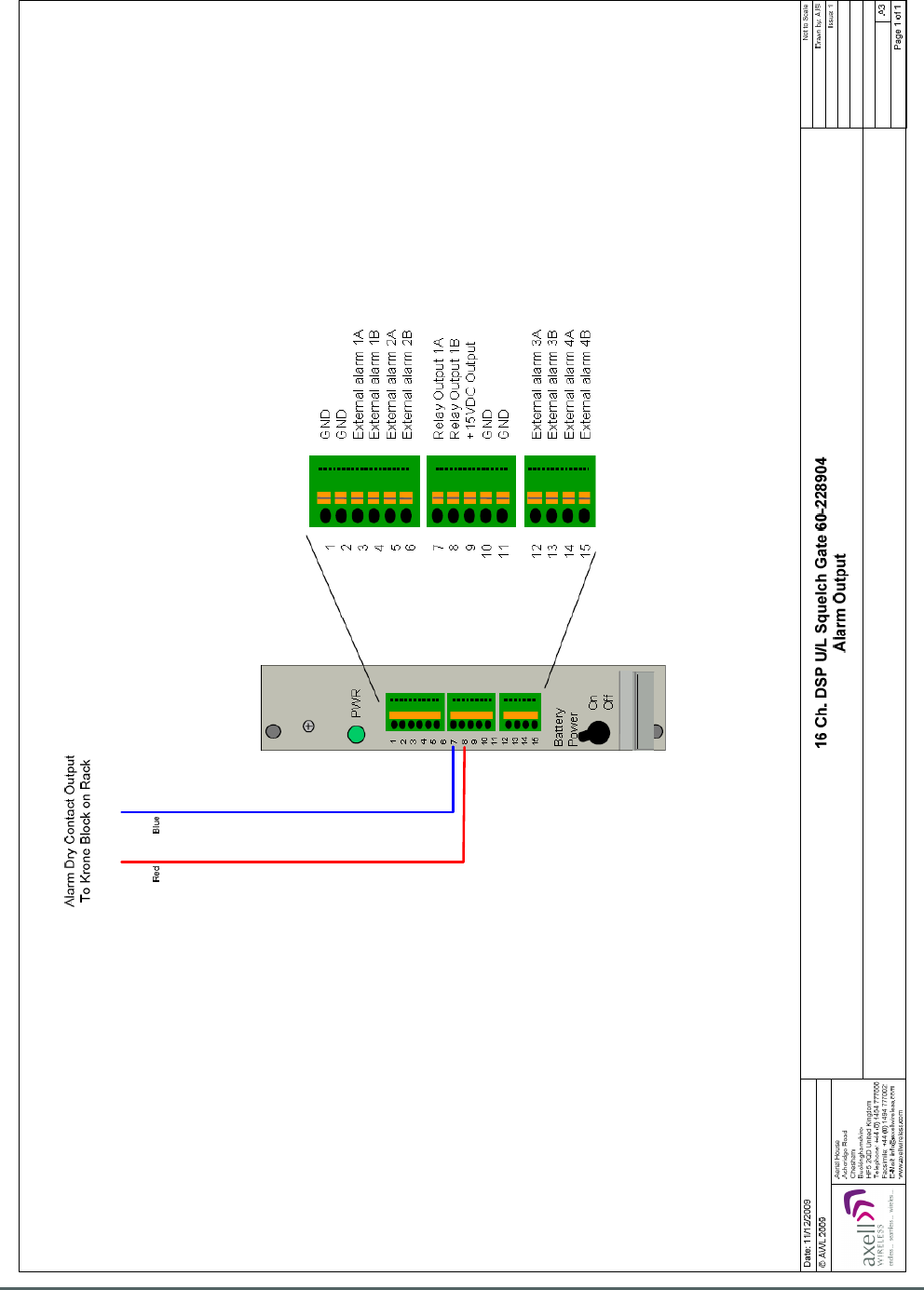
Axell Wireless Limited
Technical Literature
WMATA CRCS Redundant Antenna System
General Overview
Document Number 60-228701HBK Issue No. 3 Date 28/05/2010 Page 103 of 114
5.17.3.1. 16 Ch. DSP U/L Squelch Gate 60-228904 Alarm Output
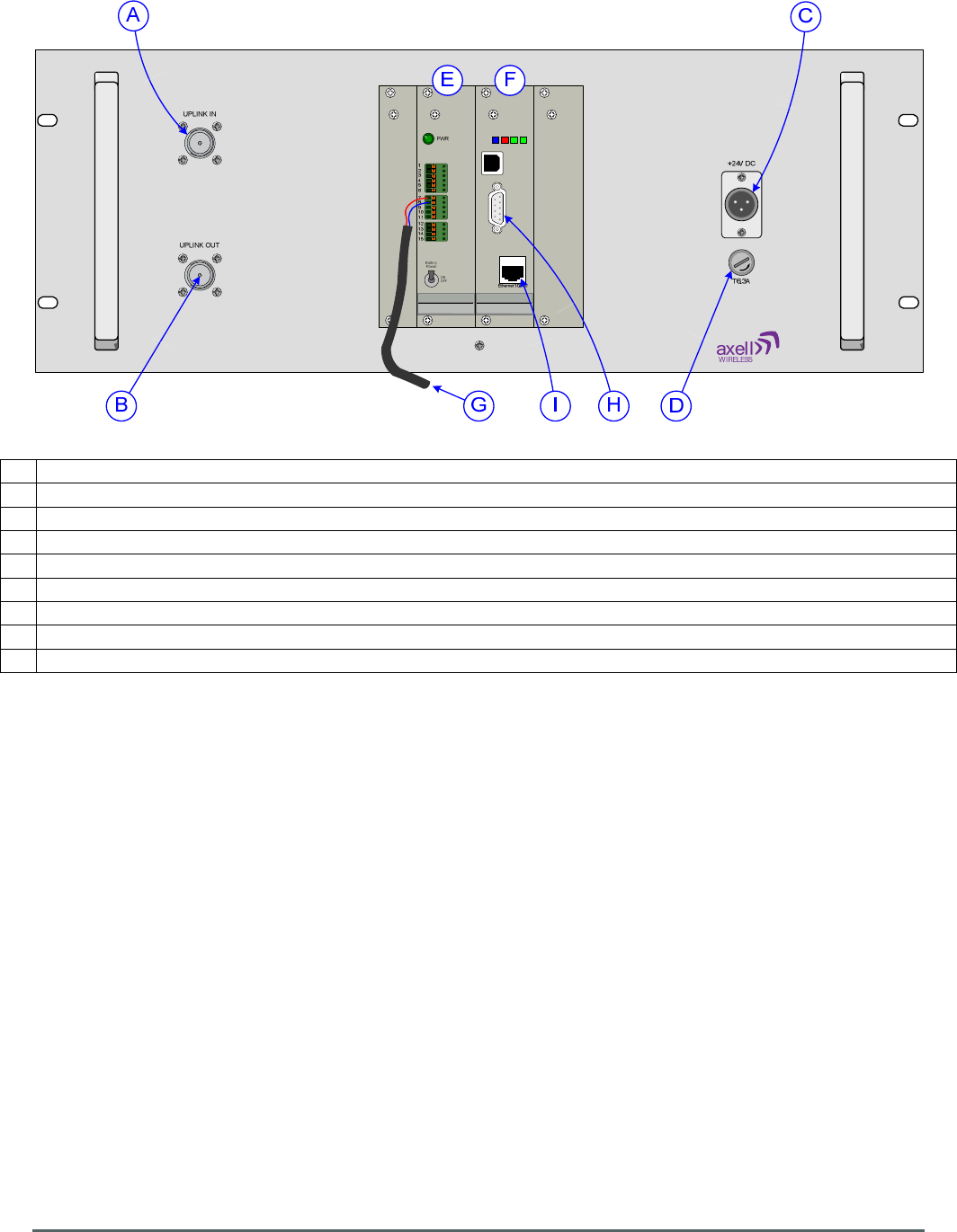
Axell Wireless Limited
Technical Literature
WMATA CRCS Redundant Antenna System
General Overview
Document Number 60-228701HBK Issue No. 3 Date 28/05/2010 Page 104 of 114
LMT Port
Modem Status
Modem Power
Status
Login
5.17.4. 16 Ch. DSP U/L Squelch Gate 60-228904 Front View
A N type port “A”, Uplink input from Combiner Unit 60-228907
B N type port “B”, Uplink output to Combiner Unit 60-228907
C 24V DC input from PSU module 96-300091 in PSU shelf 96-300090
D 6.3A fuse for DC input
E External Alarm and Battery Module J1161030
(1)
F Control Module H561003
(1)
G
Alarm to Krone Terminal Block on rack
H 9 pin “D” panel socket “LMT Port”, A local serial port enabling interrogation of alarm data by PC/laptop
I RJ45 Ethernet socket enabling interrogation of alarm data by PC/laptop
(1)
For more information on the Control Module H561003 and External Alarm and Battery Module J1161030,
see document A1829300.
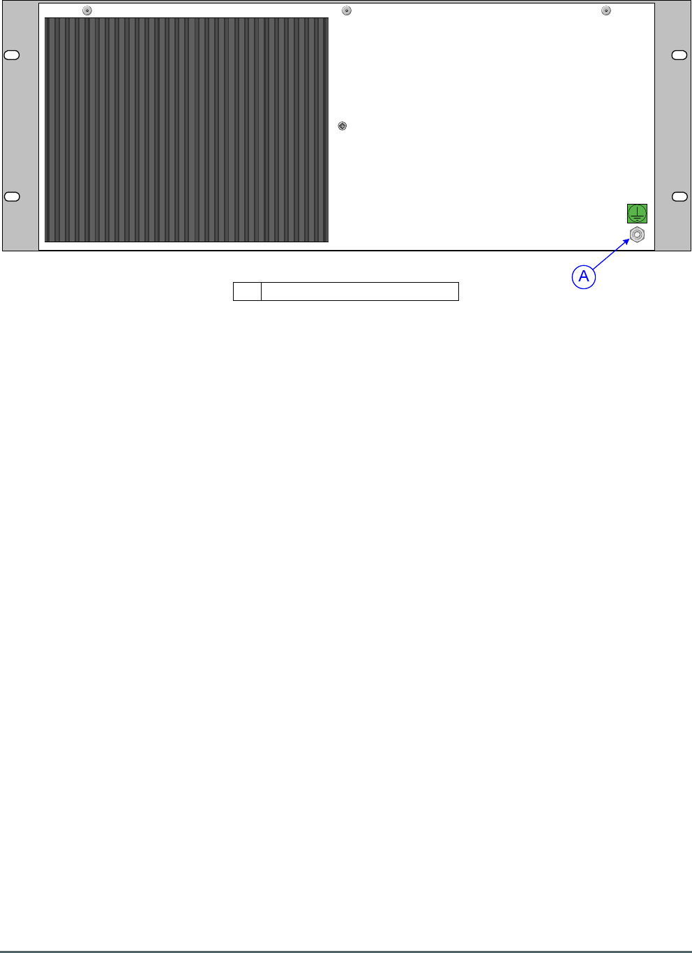
Axell Wireless Limited
Technical Literature
WMATA CRCS Redundant Antenna System
General Overview
Document Number 60-228701HBK Issue No. 3 Date 28/05/2010 Page 105 of 114
5.17.5. 16 Ch. DSP U/L Squelch Gate 60-228904 Rear View
A Earthing connection

Axell Wireless Limited
Technical Literature
WMATA CRCS Redundant Antenna System
General Overview
Document Number 60-228701HBK Issue No. 3 Date 28/05/2010 Page 106 of 114
5.18. PSU Housing Shelf 96-300090
These are 1U high, 19” Rack Mount shelves each housing two, 960W, fan cooled, AC mains driven PSU
modules (96-300091) the outputs of which are combined to provide a 24V DC supply to the other chassis in
the system. The DC leads connected to the output terminals (annotated “B” and “C” in section 5.18.2.) are
connected to two pairs of busbars, one on either side of each rack. Separate DC leads for each shelf are
then connected to the busbars, one pair of busbars feeds the shelves loaded into the front of the rack and
the second pair of busbars feeds the shelves loaded into the rear of the rack. The DC leads from the
busbars are terminated with right-angle XLR female connectors which mate with corresponding panel
mounting male XLR connectors on the front panels of those units which require a DC input.
5.18.1. PSU module 96-300091 Specification
Output
DC Voltage
24V
Rated Current
40A
Current Range
0 ~ 40A
Rated Power
960W
Ripple & Noise (max.)
200mVp-p
Voltage Adj. Range
23.2 ~ 24.8V
Voltage Tolerance
±1.0%
Line Regulation
±0.5%
Load Regulation
±0.5%
Setup, Rise Time
1000ms, 60ms/230V AC at full load
Hold Time (Typ.)
16ms/230V AC at full load
Input
Voltage Range
90 ~ 264V AC
127 ~ 370V DC
Frequency Range
47 ~ 63Hz
Efficiency (Typ.)
87%
AC Current (Typ.)
10.5A/115V AC
5.5A/230V AC
Inrush Current (Typ.)
Cold Start 50A
Leakage Current
<1.1mA / 230VAC
Protection
Over Load
105 ~ 125% rated output power
Protection type : Constant current limiting, recovers automatically
after fault condition is removed
Over Voltage
26.4 ~ 32.4V
Protection type : Shut down o/p voltage, re-power on to recover
Over Temperature
75 5°C ±5°C (TSW1) Detect on heatsink of power transistor
85 5°C ±5°C (TSW2) Detect on heatsink of power diode
Protection type : Shut down o/p voltage, recovers automatically
after temperature goes down
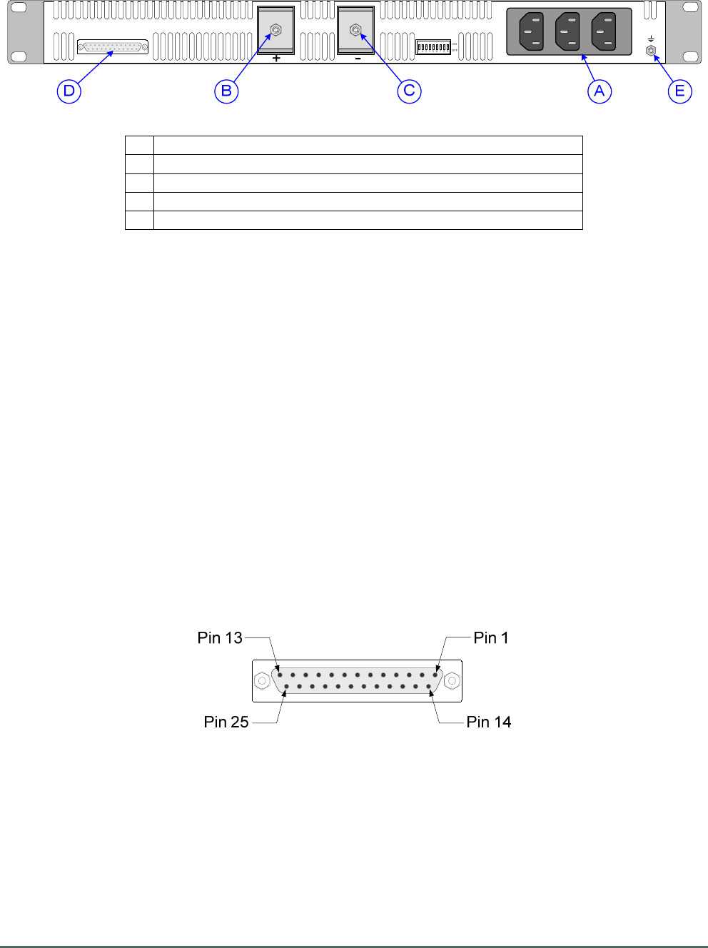
Axell Wireless Limited
Technical Literature
WMATA CRCS Redundant Antenna System
General Overview
Document Number 60-228701HBK Issue No. 3 Date 28/05/2010 Page 107 of 114
5.18.2. PSU Module Chassis 96-300090 Rear View
A AC inputs
B 24V DC terminal (connects to rack 24V busbar)
C
0V DC terminal (connects to rack 0V busbar)
D
Alarm output to Krone terminal block on rack
E Earthing connector
5.18.3. PSU Module Chassis 96-300090 Alarm Wiring
25 pin “D” panel socket, local alarm/control output to Krone terminal blocks on rack (see section 5.10)
Pin 1 ON/OFF PSU A
Pin 2 AC OK PSU A
Pin 3 DC OK PSU A
Pin 5 T-ALARM PSU A
Pin 9 AC OK PSU B
Pin 8 ON/OFF PSU B
Pin 10 DC OK PSU B
Pin 12 T-ALARM PSU B
Pin 21 -S -ve SENSING
Pin 20 +S +ve SENSING
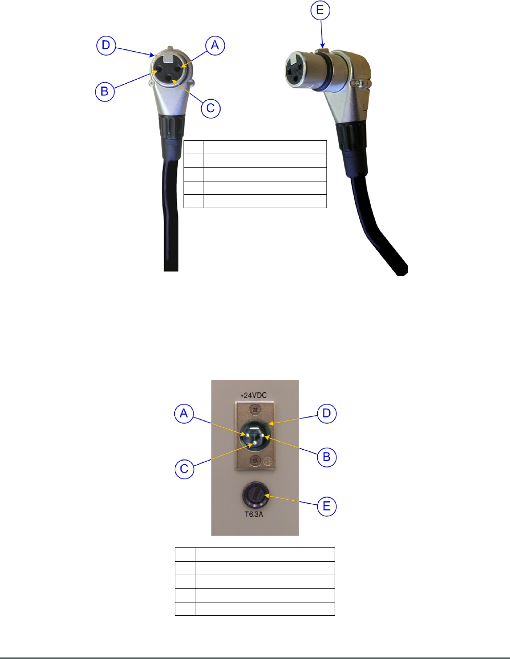
Axell Wireless Limited
Technical Literature
WMATA CRCS Redundant Antenna System
General Overview
Document Number 60-228701HBK Issue No. 3 Date 28/05/2010 Page 108 of 114
5.18.4. DC Connector Details
5.18.4.1. DC Inlet Free Socket
These are the free sockets that are connected to the rack busbars
A Pin 1, 24V (Red Wire)
B Pin 2, 0V (Black wire)
C
Pin 3, not connected
D
Guide key
E Locking/release lug
5.18.4.2. Typical DC Inlet Panel Plug
Typical DC Inlet Panel Plug showing pin allocations for the rack equipment shelves
A Pin 1, 24V (Red Wire)
B Pin 2, 0V (Black wire)
C
Pin 3, not connected
D
Guide keyway
E Fuse access

Axell Wireless Limited
Technical Literature
WMATA CRCS Redundant Antenna System
General Overview
Document Number 60-228701HBK Issue No. 3 Date 28/05/2010 Page 109 of 114

Axell Wireless Limited
Technical Literature
WMATA CRCS Redundant Antenna System
General Overview
Document Number 60-228701HBK Issue No. 3 Date 28/05/2010 Page 110 of 114
Appendix A
A.1. Glossary of Terms used in this document
Repeater or
Cell Enhancer
A Radio Frequency (RF) amplifier which can simultaneously amplify and re-broadcast
Mobile Station (MS) and Base Transceiver Station (BTS) signals.
Band Selective
Repeater
A Repeater designed for operation on a range of channels within a specified
frequency band.
Channel Selective
Repeater
A Repeater, designed for operation on specified channel(s) within a specified
frequency band. Channel frequencies may be factory set or on-site programmable.
AC Alternating Current
AGC Automatic Gain Control
BDA Bi-directional Amplifier
BTS Base Transceiver Station (Base Station)
B/W Bandwidth
C/NR Carrier-to-Noise Ratio
CRCS Comprehensive Radio Communications System
CRAS CRCS Redundant Antenna System
DAS Distributed Antenna System
DC Direct Current
Downlink (D/L) Signals transmitted from the BTS to the Mobiles
DSP Digital Signal Processing
F/O Fiber Optic
GND Ground
ID Identification (Number)
I/P Input
LCX Leaky Coaxial Cable (Leaky Feeder).
LED Light Emitting Diode
LNA Low Noise Amplifier
LPA Low Power Amplifier
Mobile(s) Hand-portable or other “Mobile” RF Transceiver equipment
MOU Master Optical Unit
MTBF Mean Time Between Failures
N/A Not Applicable
N/C (of Relays) Normally Closed
N/O (of Relays) Normally Open
OFR On Frequency Repeater
OIP3 Output Third Order Intercept Point
O/P Output
P1dB 1dB Compression Point
PA Power Amplifier
RF Radio Frequency
RHNC Relative Humidity, Non Condensing
RSA Receiver/Splitter Amplifier
RX Receiver (Received)
SDR Software-Defined Radio
S/N Serial Number
TX Transmitter (Transmitted)
Uplink (U/L) Signals transmitted from the Mobiles to the BTS
VSWR Voltage Standing Wave Ratio
Date Format Date Format used in this document is dd/mm/yyyy
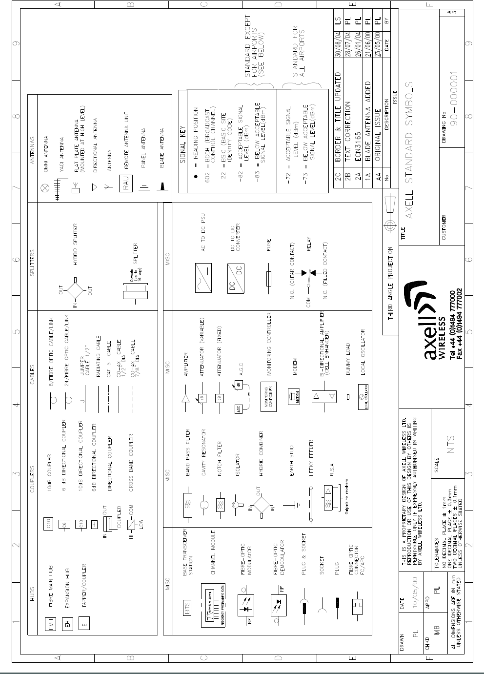
Axell Wireless Limited
Technical Literature
WMATA CRCS Redundant Antenna System
General Overview
Document Number 60-228701HBK Issue No. 3 Date 28/05/2010 Page 111 of 114
A.2. Key to Drawing Symbols used in this document
Axell Wireless Limited
Technical Literature
WMATA CRCS Redundant Antenna System
General Overview
Document Number 60-228701HBK Issue No. 3 Date 28/05/2010 Page 112 of 114
A.3. EC Declaration of Conformity
In accordance with BS EN ISO/IEC 17050-1&-2:2004
Axell Wireless Limited
Aerial House
Asheridge Road
Chesham
Buckinghamshire HP5 2QD
United Kingdom
Declares, under our sole responsibility that the following product:
Product Part Nos. and Product Descriptions
60-228701 - WMATA Carmen Turner Facility CRAS System
60-228801 - WMATA Jackson Graham Building CRAS System
60-228901 - WMATA Gallery Place Station CRAS System
In accordance with the following directives:
1999/5/EC The Radio & Telecommunications Terminal Equipment Directive Annex V
and its amending directives
Has been designed and manufactured to the following standard[s] or other normative document[s]:
BS EN 60950 Information technology equipment.
Safety. General requirements.
ETS EN 301 489-1 EMC standard for radio equipment and services.
Part 1. Common technical requirements.
I hereby declare that the equipment named above has been designed to comply with the relevant
sections of the above referenced specifications. The unit complies with all essential requirements
of the Directives.
SIGNED
B. S. Barton
Operations Director DATE: DATE: 18/11/2009
Registered Office: Aerial House, Asheridge Road, Chesham, Buckinghamshire, HP5 2QD England Registered No. 4042808 (England)
www.axellwireless.com

Axell Wireless Limited
Technical Literature
WMATA CRCS Redundant Antenna System
General Overview
Document Number 60-228701HBK Issue No. 3 Date 28/05/2010 Page 113 of 114
A.4. Waste Electrical and Electronic Equipment (WEEE) Notice
The Waste Electrical and Electronic Equipment (WEEE) Directive became law in most
EU countries during 2005. The directive applies to the disposal of waste electrical and
electronic equipment within the member states of the European Union.
As part of the legislation, electrical and electronic equipment will feature the crossed out
wheeled bin symbol (see image at left) on the product or in the documentation to show
that these products must be disposed of in accordance with the WEEE Directive.
In the European Union, this label indicates that this product should not be disposed of
with domestic or "ordinary" waste. It should be deposited at an appropriate facility to
enable recovery and recycling.

Axell Wireless Limited
Technical Literature
WMATA CRCS Redundant Antenna System
General Overview
Document Number 60-228701HBK Issue No. 3 Date 28/05/2010 Page 114 of 114
A.5. Document Amendment Record
Issue
No.
Date Incorporated
by
Section
Amended
Reason for new issue
1 18/11/2009 AJS/GD Draft
2 15/02/2010 AJS Customer changes CRCS &
CRAS
3 28/05/2010 AJS Reformat to US Letter size