PBE Europe as Axell Wireless 80-330555 Q115525 Private Land Mobile Repeater User Manual 80 330501HBKM
Axell Wireless Q115525 Private Land Mobile Repeater 80 330501HBKM
Manual

STTRS DOCUMENTATION
Document Number 80-330501HBKM – Issue A - Draft Page 408 of 500
22. INTERNATIONAL STATION 800MHZ BDA (80-330555-1)
Rack number CR9-CR-07
International Station 800MHz BDA (80-330555-1)
Section Component
Part Component Part Description Qty Per
Assembly
22.3.1. 50-132203 800MHz Output Quadplexer/Combiner 1
22.3.2. 50-132205 800MHz 5 Cavity Combiner System 2
STTRS DOCUMENTATION
Document Number 80-330501HBKM – Issue A - Draft Page 409 of 500
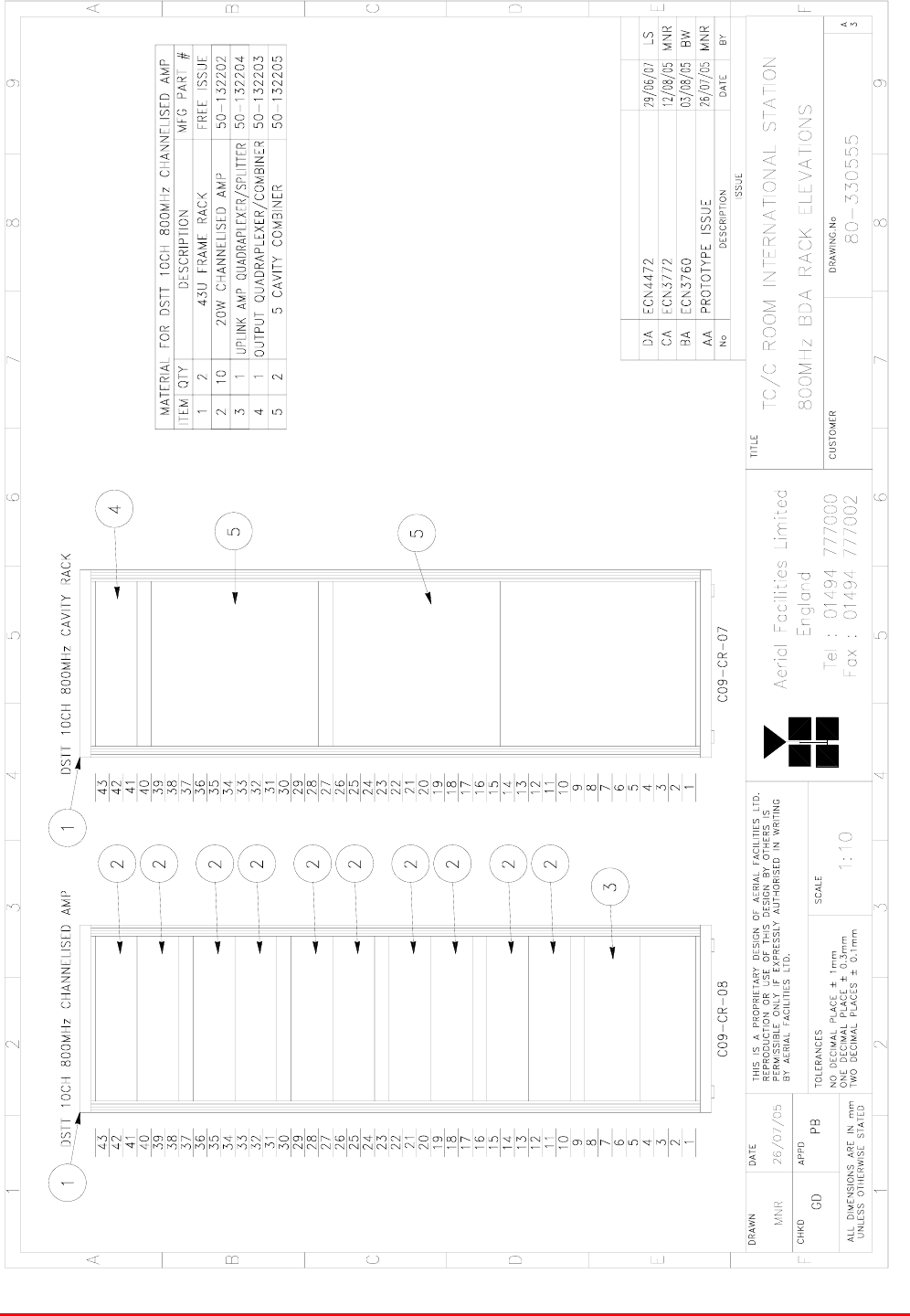
22.1. International Station 800MHz BDA (80-330555-1) Rack elevation
Drawing number 80-330555
STTRS DOCUMENTATION
Document Number 80-330501HBKM – Issue A - Draft Page 410 of 500
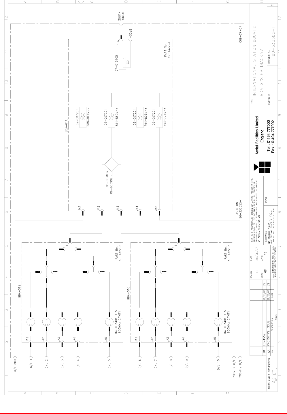
22.2. International Station 800MHz BDA (80-330555-1) System diagram
Drawing number 80-330585-1

STTRS DOCUMENTATION
Document Number 80-330501HBKM – Issue A - Draft Page 411 of 500
22.3. International Station 800MHz BDA (80-330555-1) Major Components
22.3.1. 800MHz Output Quadplexer/Combiner (50-132203)
3U rack mount tray
800MHz Output Quadplexer/Combiner (50-132203) List of major Components
Section Component
Part Component Part Description Qty Per
Assembly
22.3.1.3. 02-007206 Bandpass Filter 4
22.3.1.4. 05-003007 4 Port Hybrid Coupler 1
22.3.1.5. 07-015105 Wideband Asymmetric Coupler 1
22.3.1.6. 09-000902 Dummy load 1
STTRS DOCUMENTATION
Document Number 80-330501HBKM – Issue A - Draft Page 412 of 500
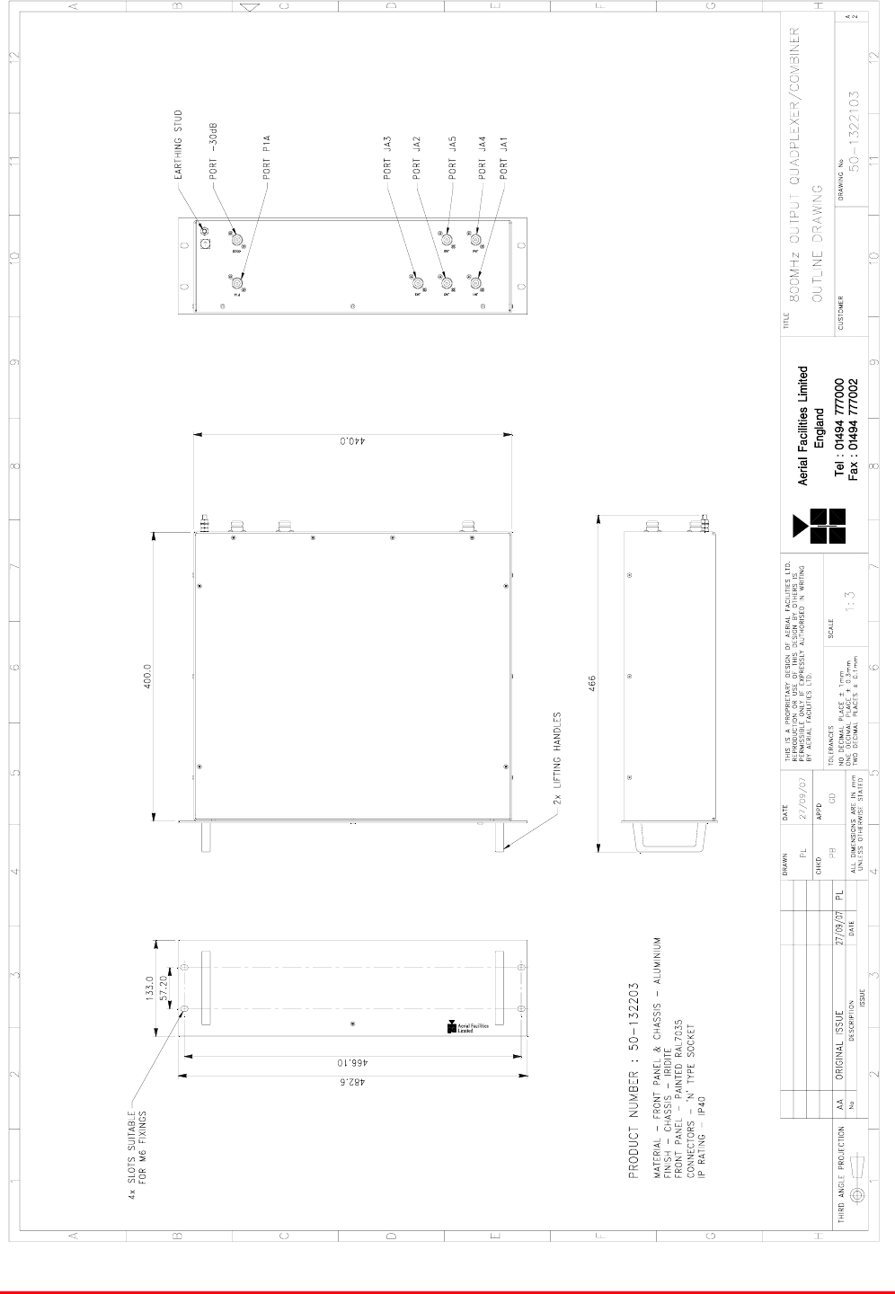
22.3.1.1. 800MHz Output Quadplexer/Combiner (50-132203) Outline Drawing
Drawing number 50-1322103
STTRS DOCUMENTATION
Document Number 80-330501HBKM – Issue A - Draft Page 413 of 500
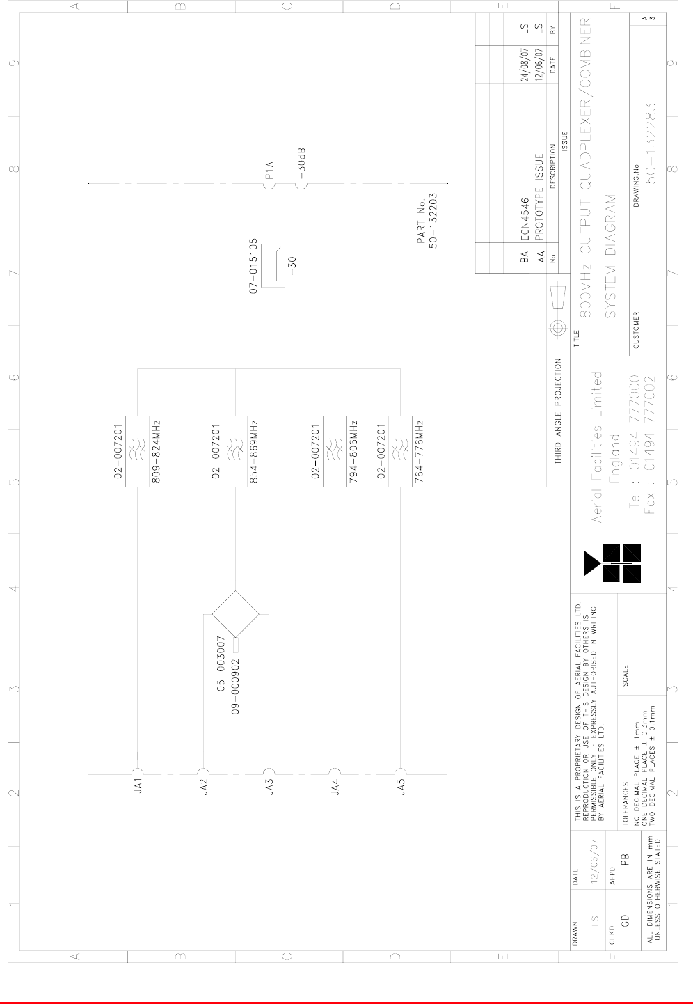
22.3.1.2. 800MHz Output Quadplexer/Combiner (50-132203) System Diagram
Drawing number 50-132283
STTRS DOCUMENTATION
Document Number 80-330501HBKM – Issue A - Draft Page 414 of 500
22.3.1.3. Bandpass Filter (02-007206)
The bandpass filters are multi-section designs with a bandwidth dependent upon the passband
frequencies, (both tuned to customer requirements). The response shape is basically Chebyshev with
a passband design ripple of 0.1dB. The filters are of slot coupled, folded combline design, and are
carefully aligned during manufacture in order to optimise the insertion loss, VSWR and
intermodulation characteristics of the unit. The tuned elements are silver-plated to reduce surface
ohmic losses and maintain a good VSWR figure and 50Ω load at the input and output ports.
Being passive devices, the bandpass filters should have an extremely long operational life and require
no maintenance. Should a filter be suspect, it is usually most time efficient to replace the module
rather than attempt repair or re-tuning.
No adjustments should be attempted without full network sweep analysis facilities to monitor both
insertion loss and VSWR simultaneously.
02-007206 Specification
PARAMETER SPECIFICATION
Response type Chebyshev
Frequency range 800 - 950MHz *
Bandwidth 25MHz *
Number of sections 8
Insertion loss 1.2 dB
VSWR better than 1.2:1
Connectors SMA female
Power handling 100W max
operation -20°C to +60°C Temperature
range storage -40°C to +70°C
Weight 3 kg (typical) *tuned to Customer's specification
22.3.1.4. 4 Port Hybrid Coupler (05-003007)
This transmitter hybrid coupler is a device for accurately matching two or more RF signals to single or
multiple ports, whilst maintaining an accurate 50Ω load to all inputs/outputs and ensuring that the
insertion losses are kept to a minimum. Any unused ports should be terminated with an appropriate
50Ω load. In this specific instance one port of 4 Port Hybrid Coupler (05-003007) is terminated with
Dummy load 09-000902 (see below).
05-003007 Specification
PARAMETER SPECIFICATION
Frequency range 700-900MHz
Bandwidth 200MHz
Rejection >14dB
Insertion loss 6.5dB (in band, typical)
Connectors SMA
Weight <1.0kg
operational -10%C to +60%C Temperature
range storage -20%C to +70%C

STTRS DOCUMENTATION
Document Number 80-330501HBKM – Issue A - Draft Page 415 of 500
22.3.1.5. Wideband Asymmetric Coupler (07-015105)
The purpose of Wideband Asymmetric Coupler (07-015105) is to tap off a known portion (in this case
30dB) of RF signal from transmission lines and to combine them, for example through splitter units for
different purposes (alarms/monitoring etc.), whilst maintaining an accurate 50Ω load to all
ports/interfaces throughout the specified frequency range. They are known formally as directional
couplers as they couple power from the RF mainline in one direction only.
07-015105 Specification
PARAMETER SPECIFICATION
Construction Inductive air gap
Frequency 800-2500MHz
Through loss 0.4dB (typical)
Coupling level -30dB ±0.5dB
Isolation N/A
Weight <1.0kg
Connectors SMA, female
operation -20°C to +60°C
Temperature
range storage -40°C to +70°C
22.3.1.6. Dummy load 09-000902
When a combiner system is used to split or combine RF signals, in many cases it is most cost
effective to use a standard stock item 4, 6 or 8 port device where, in fact, only a 3 or 6 port device is
needed. In this case 4 Port Hybrid Coupler (05-003007) has one of its ports terminated with an
appropriate Dummy Load in order to preserve the correct impedance of the device over the specified
frequency range.
09-000902 specification
PARAMETER SPECIFICATION
Frequency Range 0 - 2500 MHz
Power Rating 25 Watts continuous
VSWR Better than 1.1:1
Impedance 50 Ohms
Temperature Range -20 to +60°C
RF Connectors N Type female
Dimension 110.3mm x 38.1mm x
Weight 485 grams
Finish Black Anodised
RF Connector N Type male
Environmental IP66
MTBF >180,000 hours

STTRS DOCUMENTATION
Document Number 80-330501HBKM – Issue A - Draft Page 416 of 500
22.3.2. 800MHz 5 Cavity Combiner System (50-132205)
800MHz 5 Cavity Combiner System (50-132205) consists of 5 Dielectric Cavity Resonators mounted
on two 3U rack mount panels, three on one panel and two on the other
800MHz 5 Cavity Combiner System (50-132205) List of Major Components
Section Component
Part Component Part Description Qty Per
Assembly
22.3.2.3. 04-003401 Dielectric Cavity Resonator 5
STTRS DOCUMENTATION
Document Number 80-330501HBKM – Issue A - Draft Page 417 of 500
800MHz 5CH CAVITY COMBINER OUTLINE DRAWING
1:3 50-1322105
GD
26/10/2007
PB
26/10/2007
AA
02/10/07
PL
8x SLOTS SUITABLE FOR M6 FIXINGS
532.2 12U
265.9 6U 265.9 6U
I1
466.00
482.50
37.7 190.50 37.7 190.50
PRODUCT NUMBER : 50-132205
MATERIAL - FRONT PANEL & CHASSIS - ALUMINIUM
FINISH - FRONT PANEL - IRIDITE
FRONT PANEL - PAINTED RAL7035 (FRONT FACE & EDGES)
CONNECTORS - `N' TYPE SOCKET
AA ORIGINAL ISSUE PL
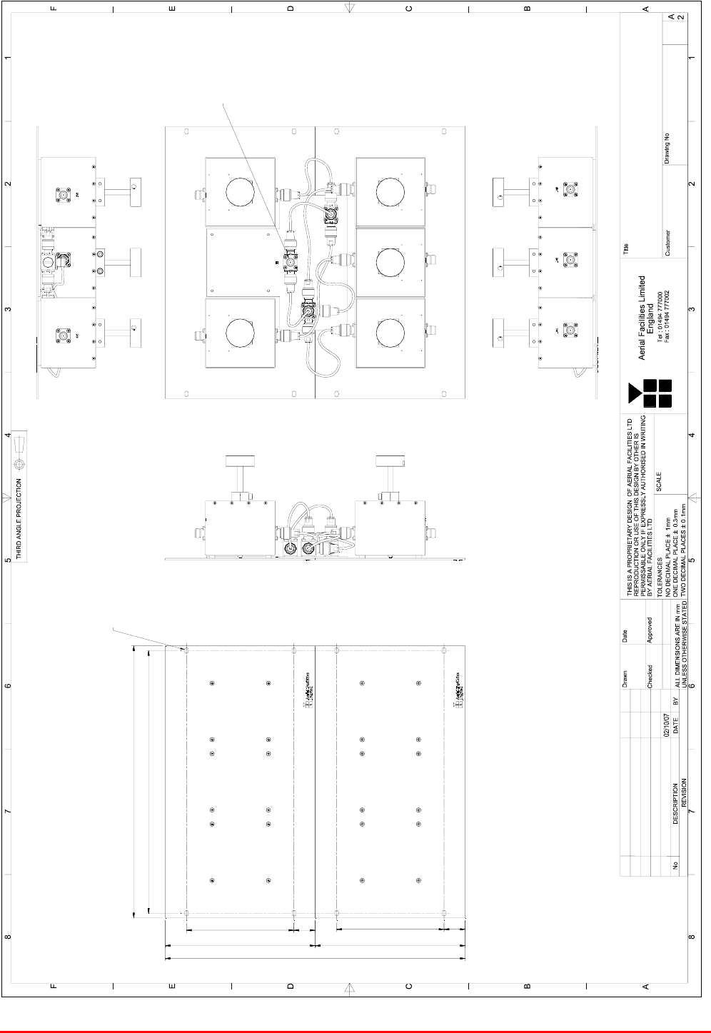
22.3.2.1. 800MHz 5 Cavity Combiner System (50-132205) Outline Drawing
Drawing number 50-1322105
STTRS DOCUMENTATION
Document Number 80-330501HBKM – Issue A - Draft Page 418 of 500
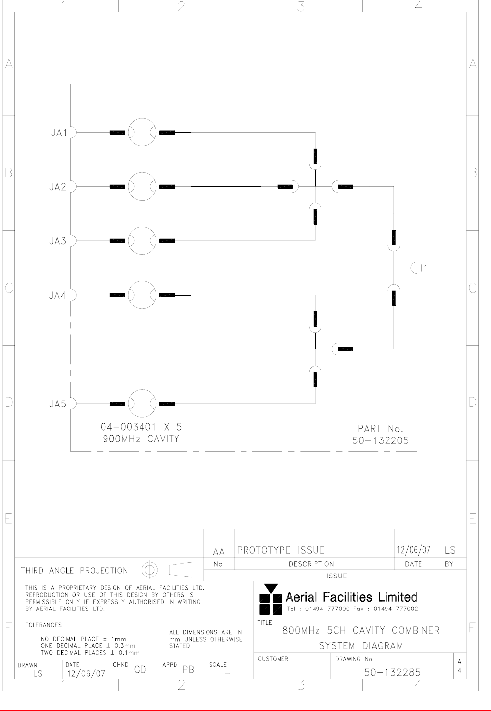
22.3.2.2. 800MHz 5 Cavity Combiner System (50-132205) System Diagram
Drawing number 50-132285

STTRS DOCUMENTATION
Document Number 80-330501HBKM – Issue A - Draft Page 419 of 500
22.3.2.2. Dielectric Cavity Resonator (04-003401)
Cavity resonators are used in this system for their high Q factor response and power handling
characteristics. Being finely tuned items, they can be prone to being de-tuned by mechanical shock or
vibration therefore these units should be handled, stored and installed with care.
Note that the cavities are coupled together using critical length harnesses. If any cable is to be
changed the exact same length and type of cable should be used for replacement.
04-003401 Specification
Specification Parameter
Frequency Range 800 - 950MHz *
Bandwidth 25 kHz*
Insertion Loss < 1.0 dB
Return Loss > 15 dB (at both ports)
Attenuation > 10 dB at Fc ± 1 MHz
Power Handling (CW) 20W
Environmental IP54
Size 124mm x 158mm x 157mm**
Weight 1.5 kg
Connectors N female
operation -20°C to +60°C
Temperature
range storage -40°C to +70°C
*Tuned to Customer’s specification
**Height is dependant upon position of tuning plunger