PBE Europe as Axell Wireless A207SERIES MBF-T-8-17-19S Tri Band Repeater User Manual manual
Axell Wireless MBF-T-8-17-19S Tri Band Repeater manual
UserManual.wiki
>
PBE Europe as Axell Wireless
>
A207SERIES User Manual
manual
Navigation menu
Upload a User Manual
Namespaces
Wiki Guide
HTML
PDF
Info
Views
User Manual
Discussion / Help
Navigation


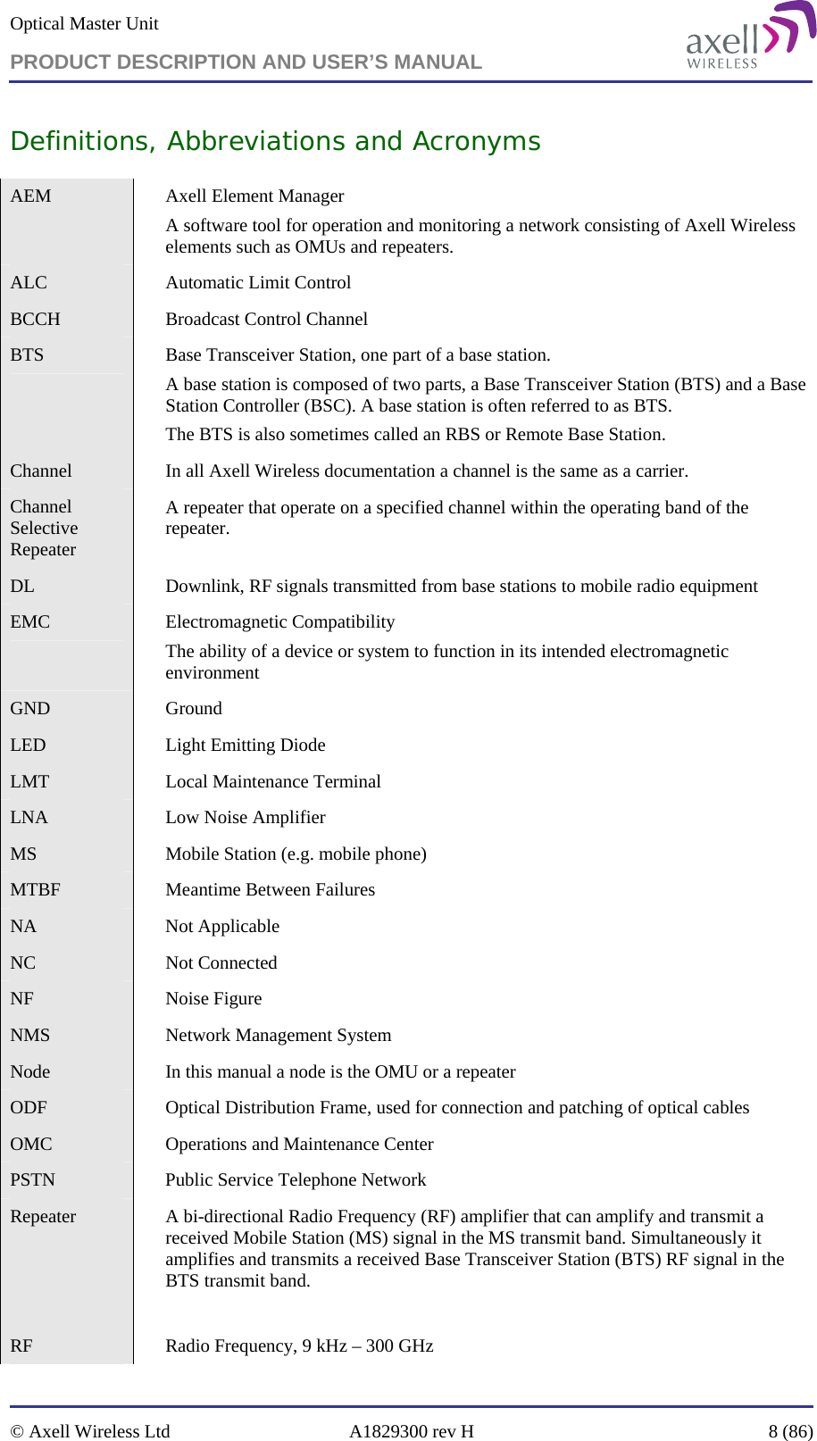
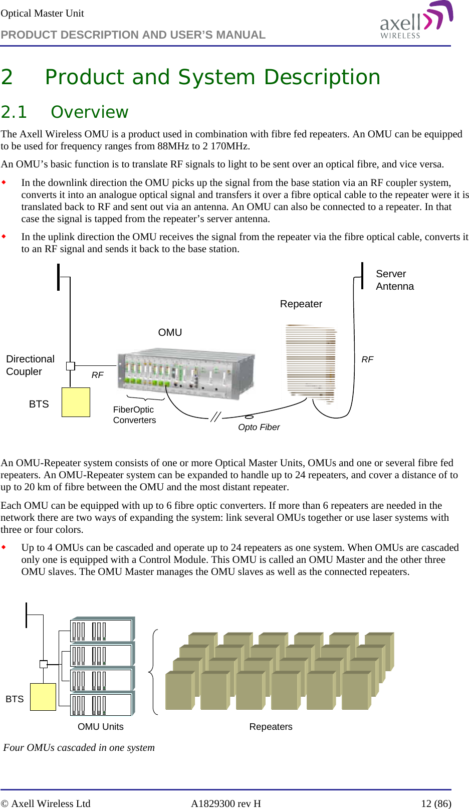


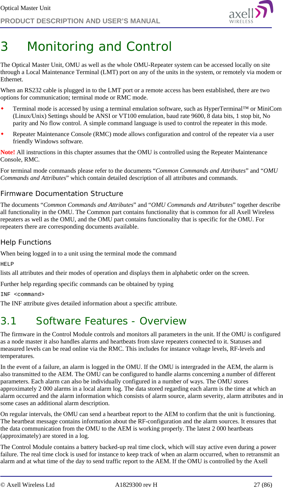
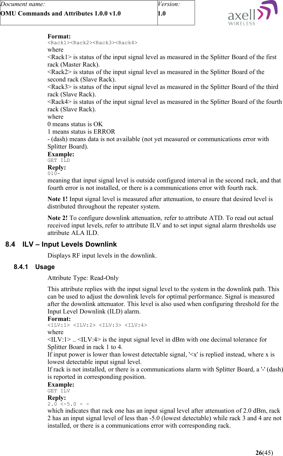
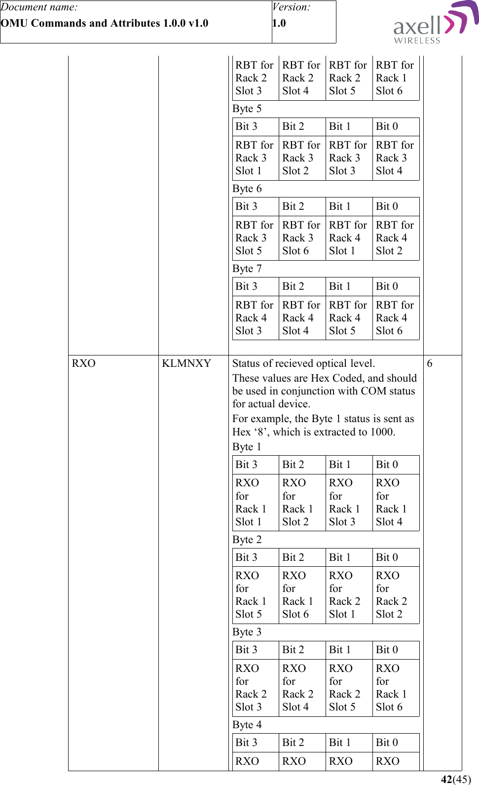
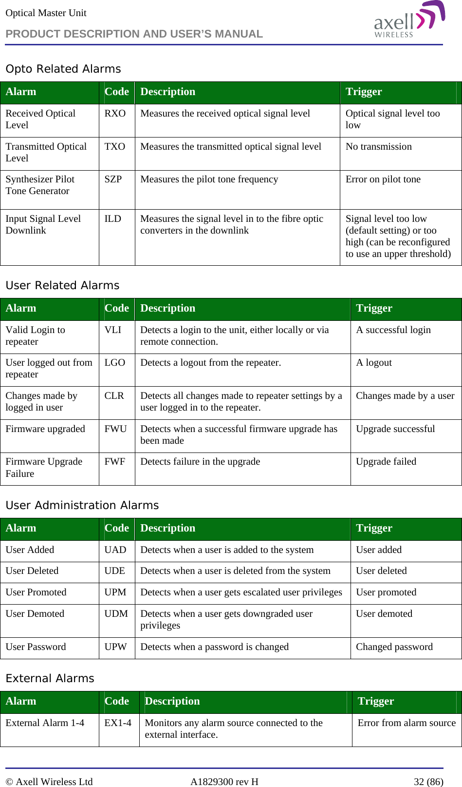
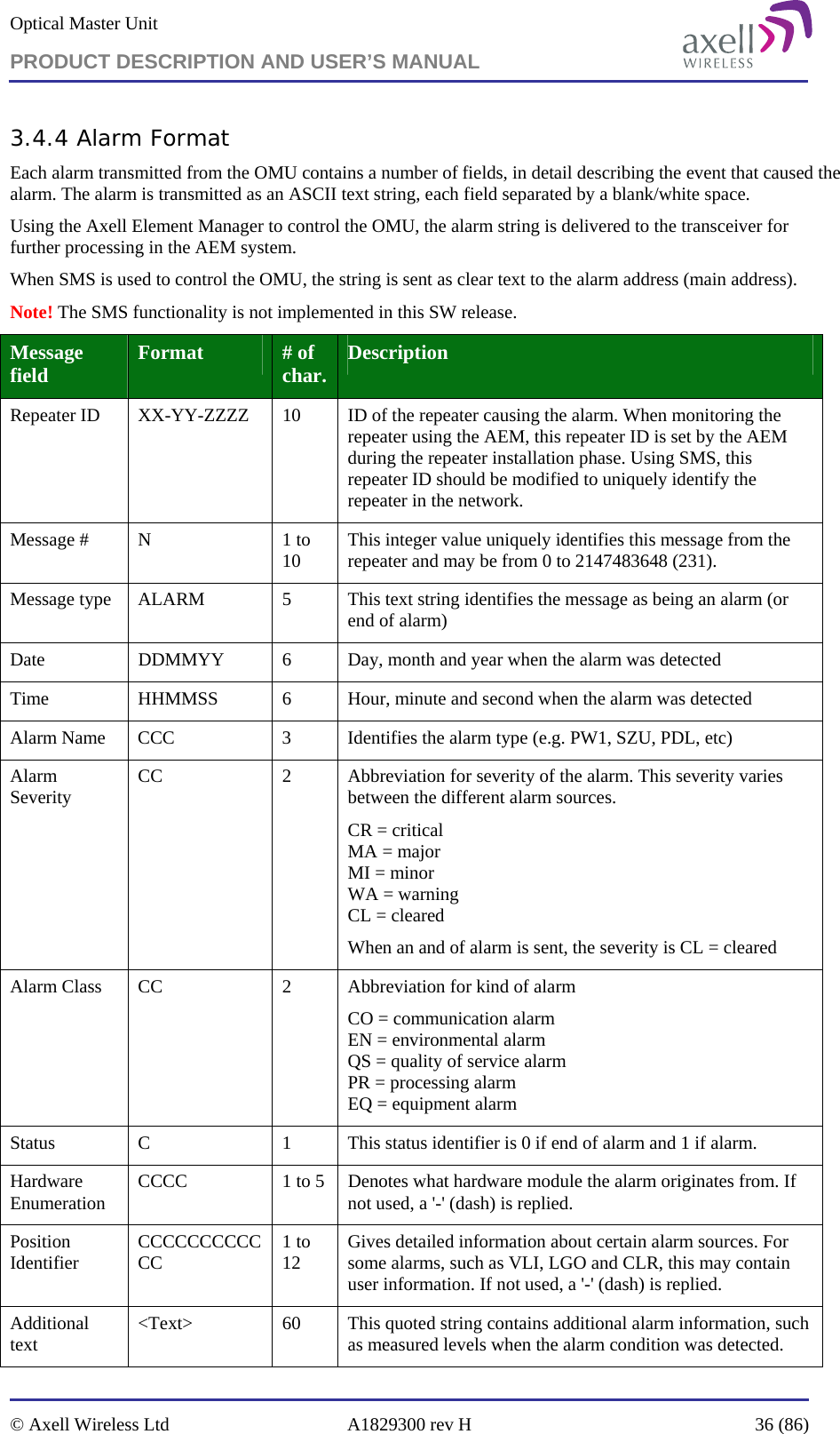
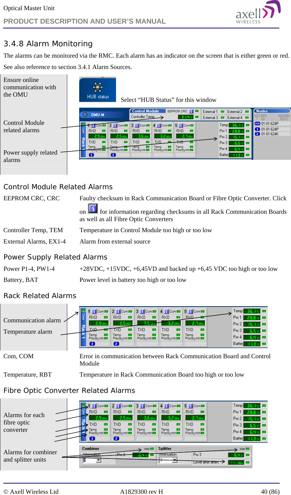
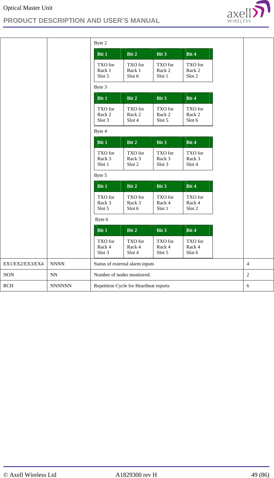
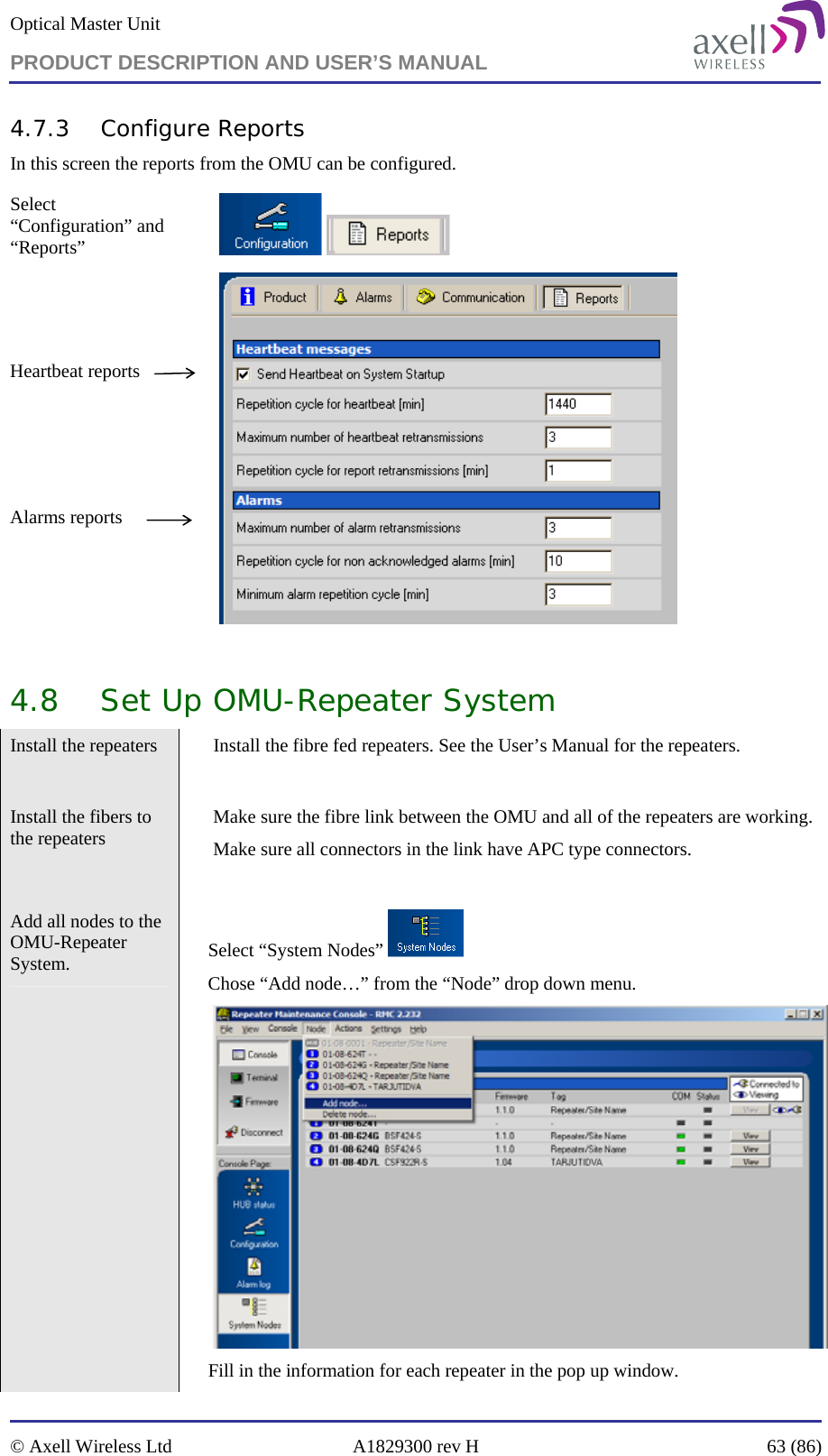
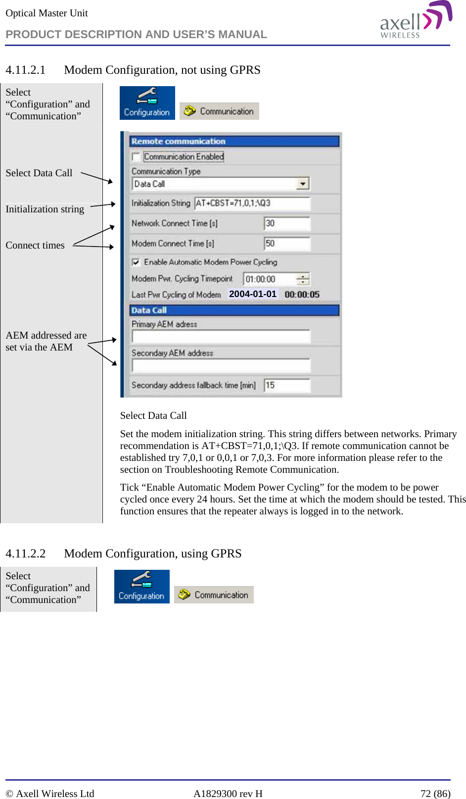
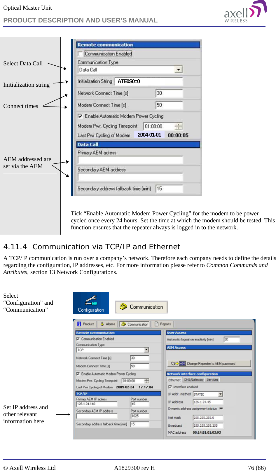
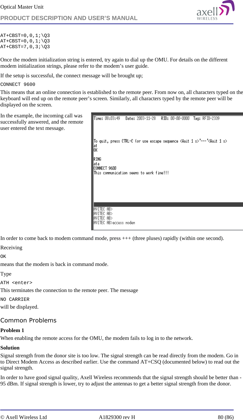
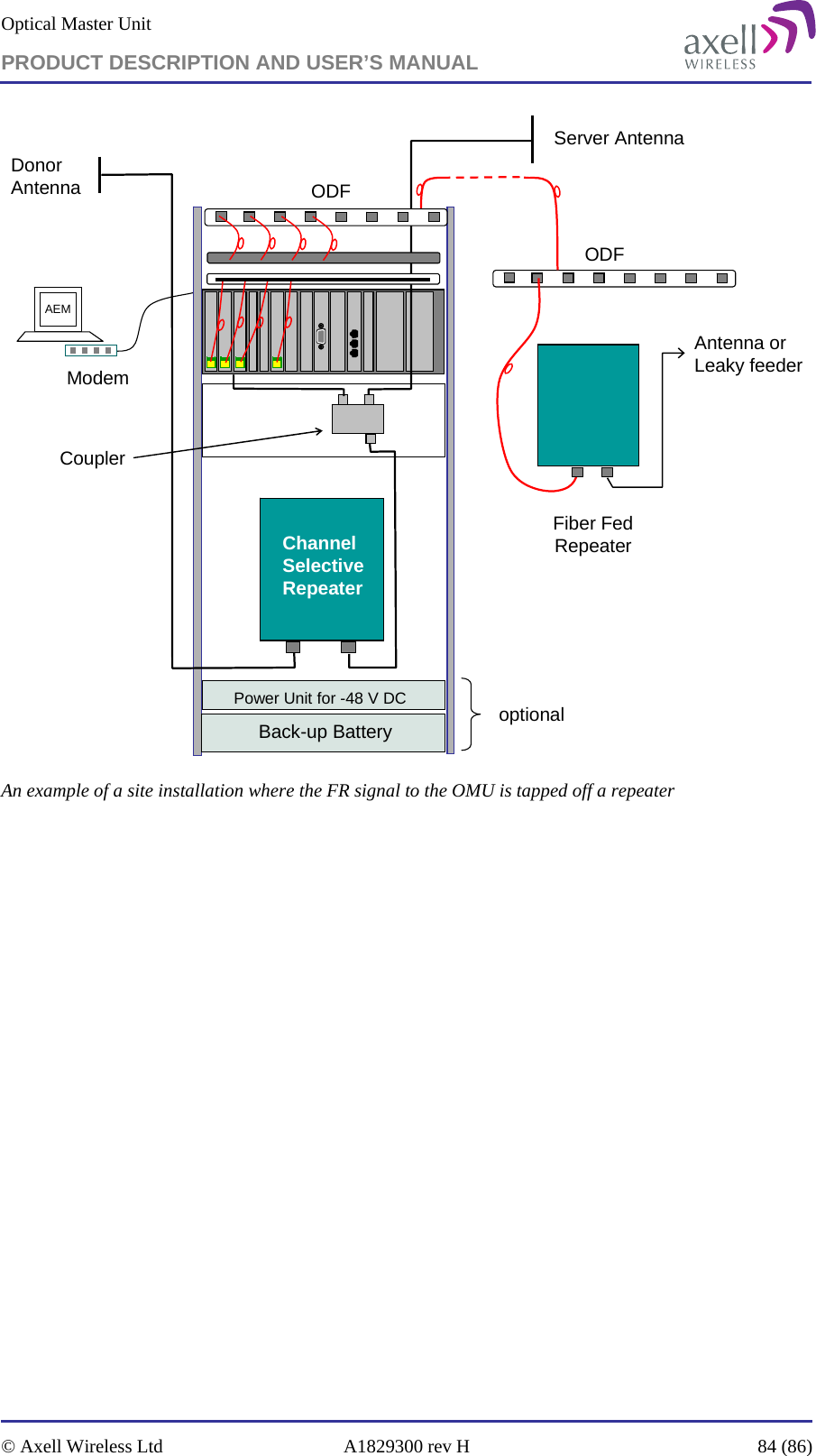
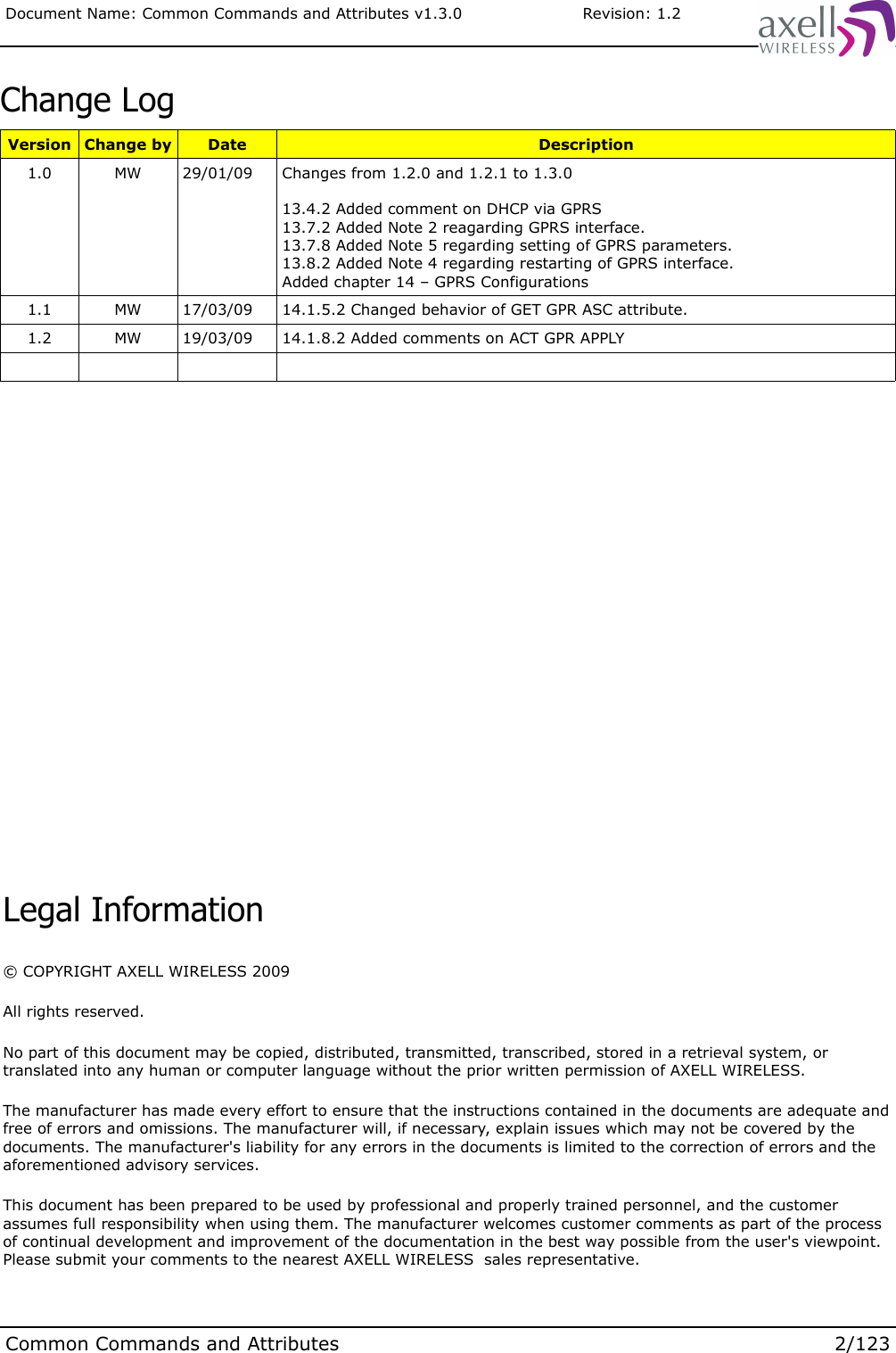
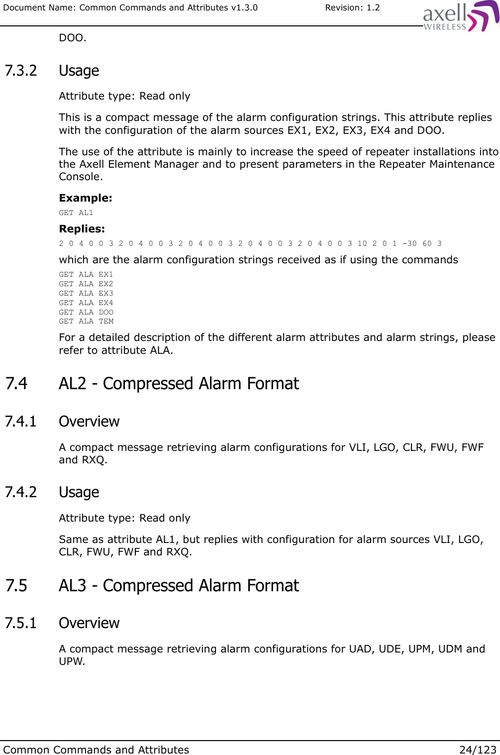
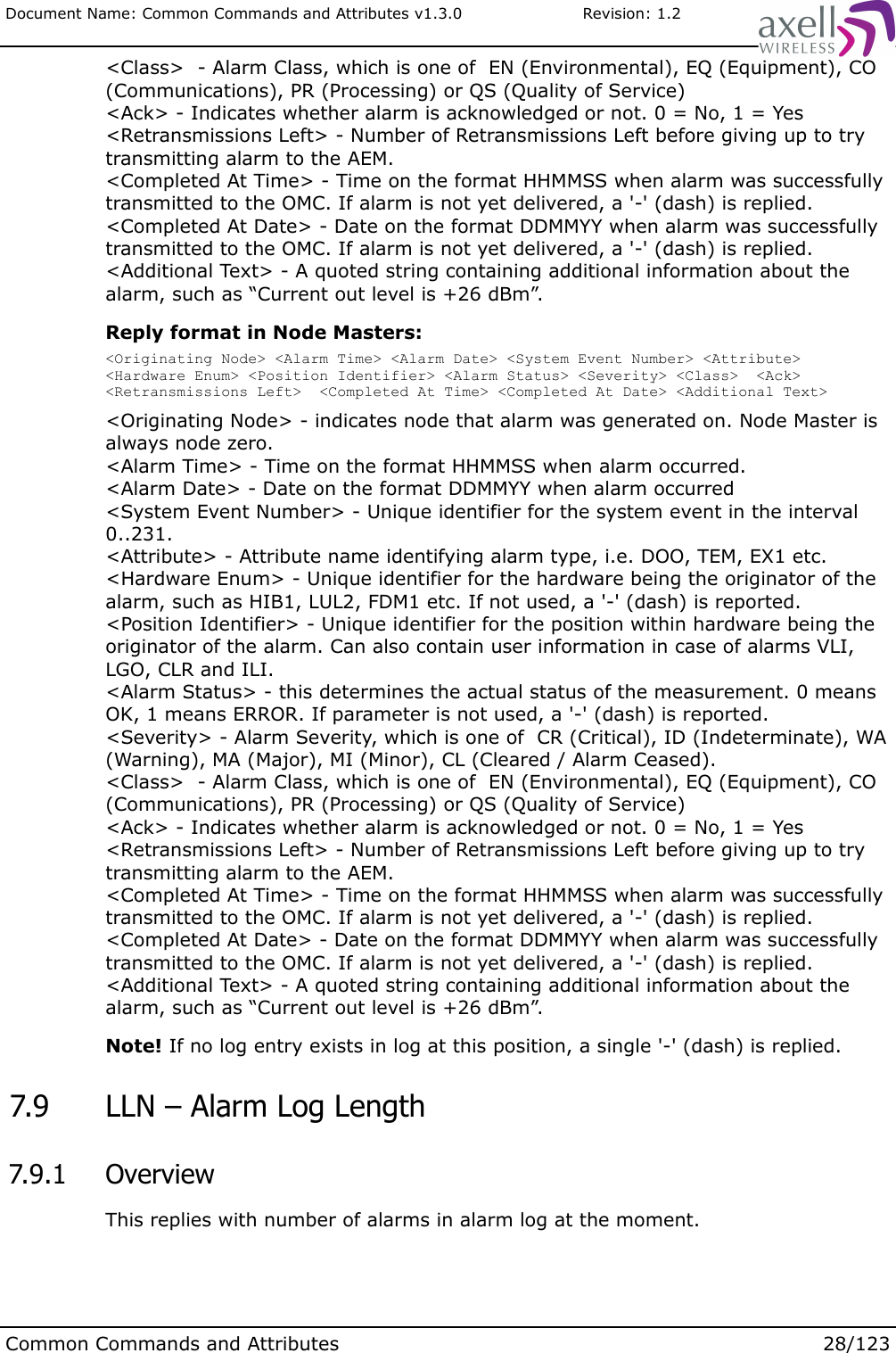
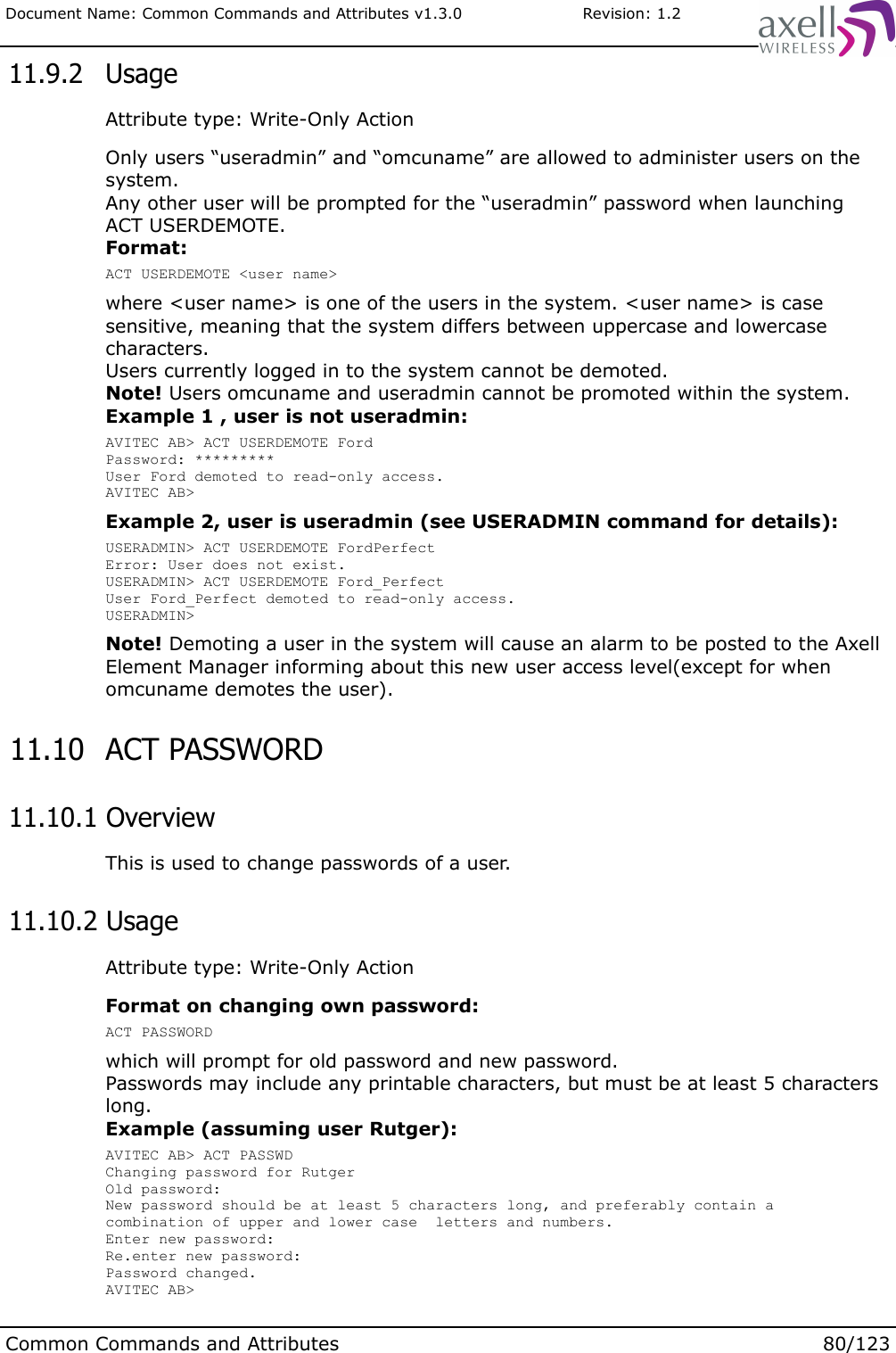
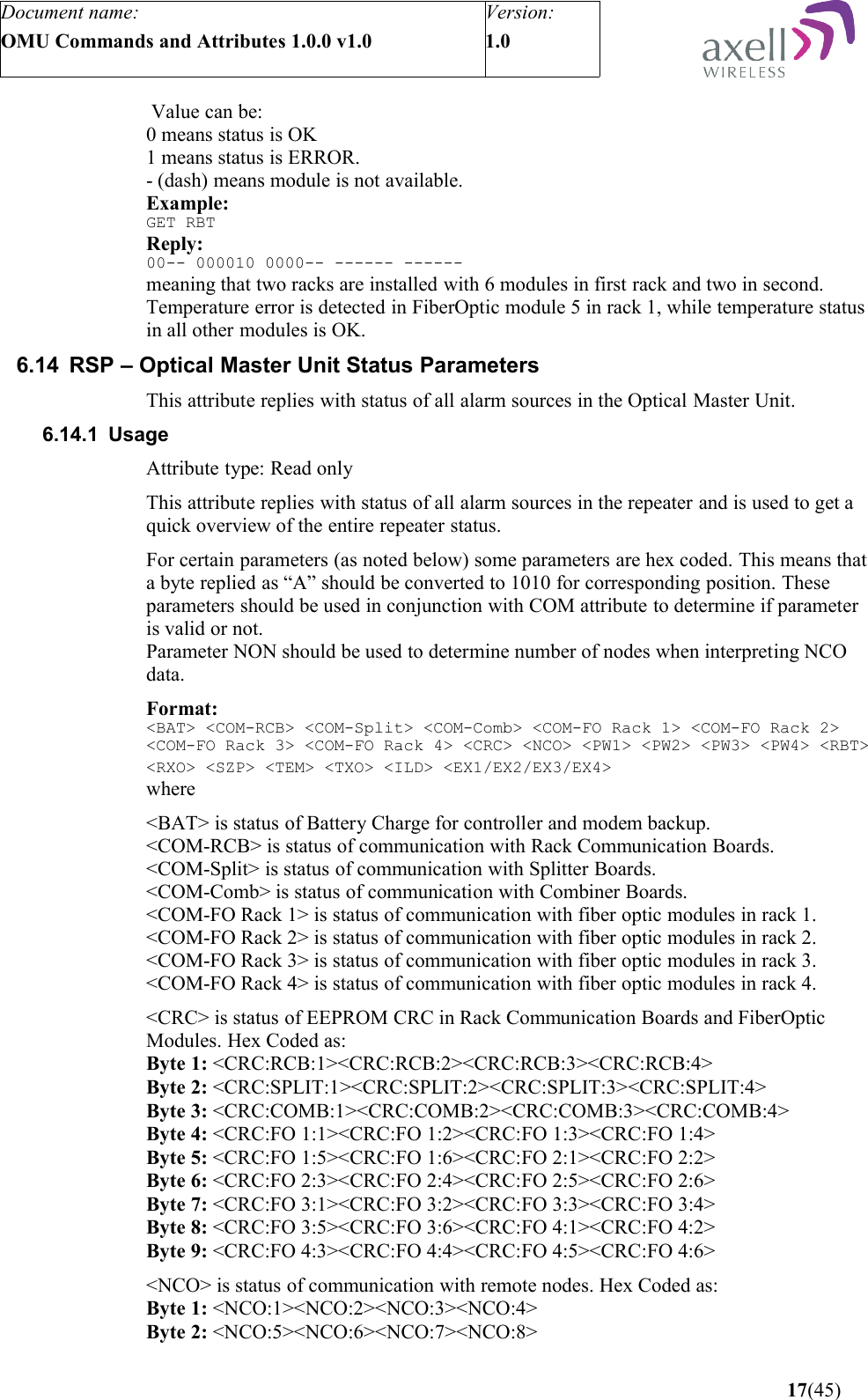
![Optical Master Unit PRODUCT DESCRIPTION AND USER’S MANUAL © Axell Wireless Ltd A1829300 rev H 29 (86) AVITEC AB> @2J34 GET MDL BSF424-I AVITEC AB> Node ID Addressing A node can also be addressed using the full Node ID. Example: AVITEC AB> @01-01-2J34 GET TAG SITE3_TUNNEL_OPENING AVITEC AB> Direct Node Addressing When many attributes are intended for another node, the user can enter Direct Node Access mode, where the node the user is logged in redirects all commands to the destination node. This mode is configured by sending the command: SET DNA [Node Address] where any of the node addressing modes can be used as Node Address. When going into direct node addressing, the command prompt is changed to reflect what node is currently addressed: AVITEC AB> SET DNA 2J34 AVITEC AB @2J34> Refer to attribute DNA in OMU Command and Attribute Summary for further details on direct node addressing. 3.2.3 System Wide Parameters System Wide Parameters are parameters that when configured should be written to all nodes in the system. When setting a system wide parameter, the parameter is always set in the node master, which is then responsible for setting the parameter to all other nodes. If attempting to set a system wide parameter from a node as access to the node master is not available, setting the parameter will fail. The following “standard” parameters are treated as system wide parameters (please refer to OMU Command and Attribute Summary for details): LMT Local Maintenance Terminal timeout TIM Setting the time DAT Setting the date TPD Setting the time for sending traffic / utilization report to the AEM UID User ID’s PWD Passwords RID Repeater ID In slave repeaters the OMU is responsible for the communication with the AEM. 3.2.4 Node Access An operator can login to the OMU-Repeater system from any node in the network and access all parameters in all nodes, including those in the node master unit. This can be done using a serial cable connected to the node’s LMT-port or by remote access over a modem or Ethernet. Select “System Nodes”](https://usermanual.wiki/PBE-Europe-as-Axell-Wireless/A207SERIES/User-Guide-1216782-Page-30.png)
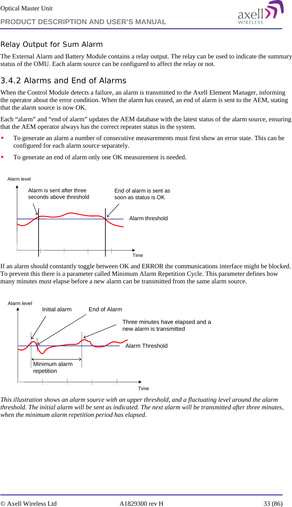
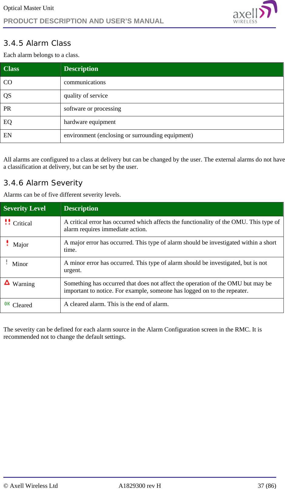
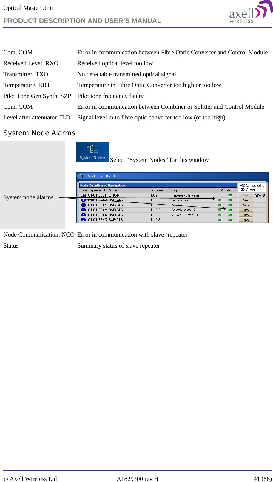

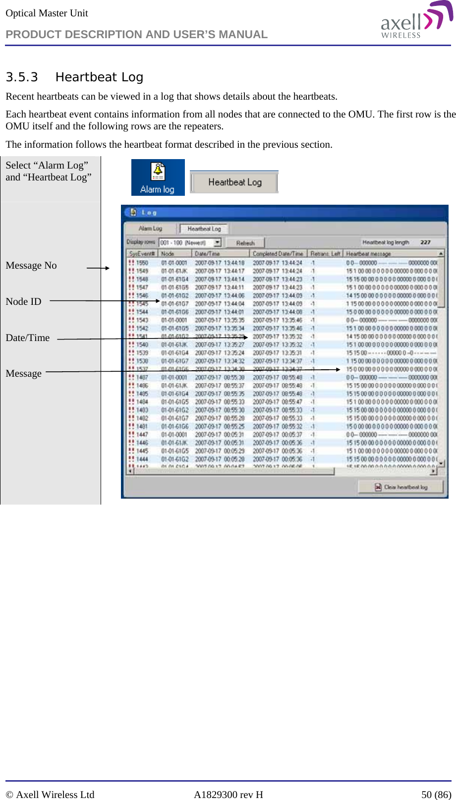


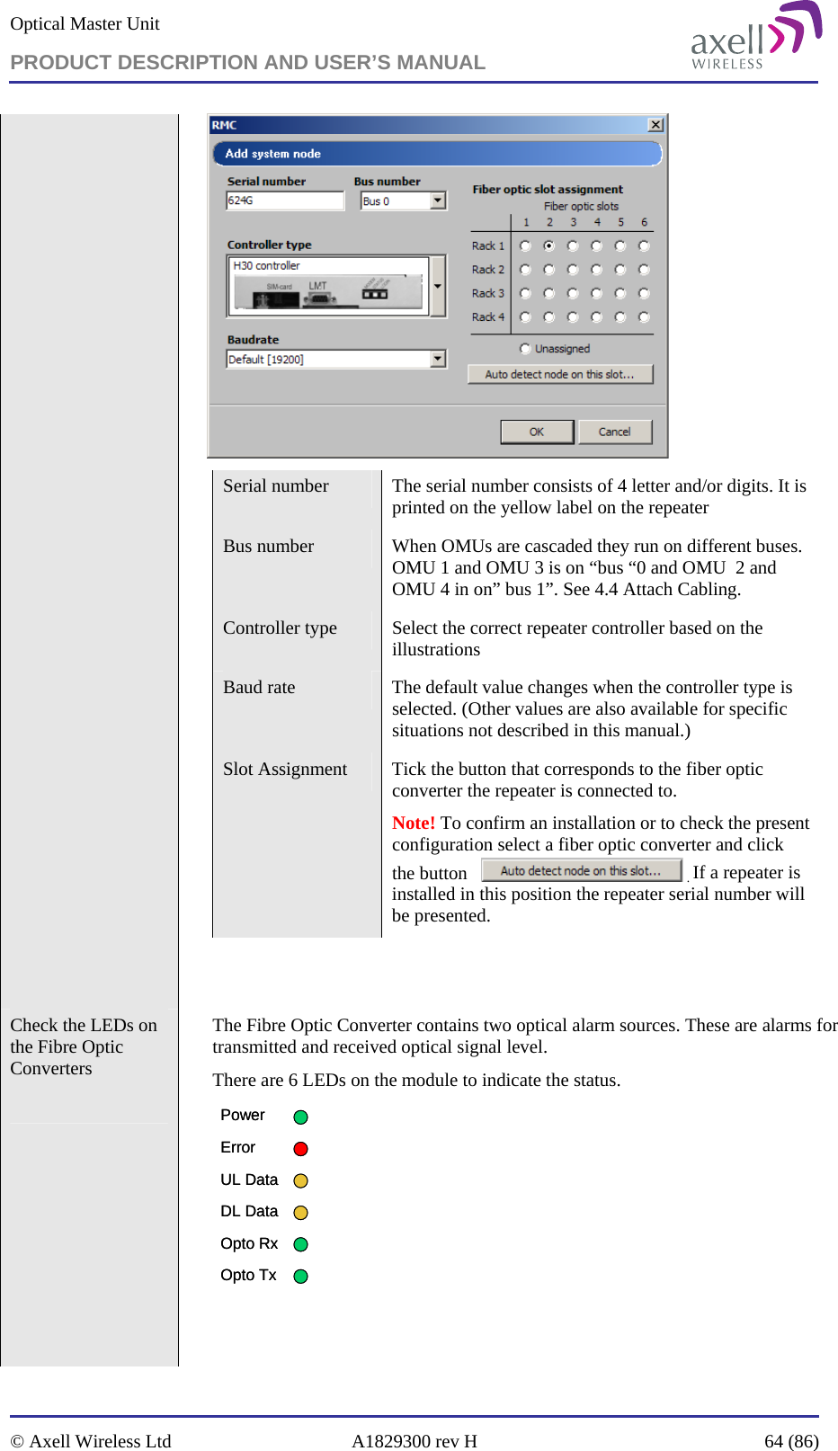

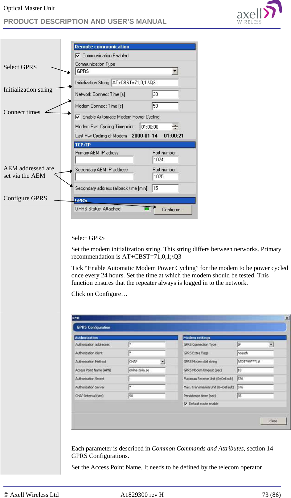
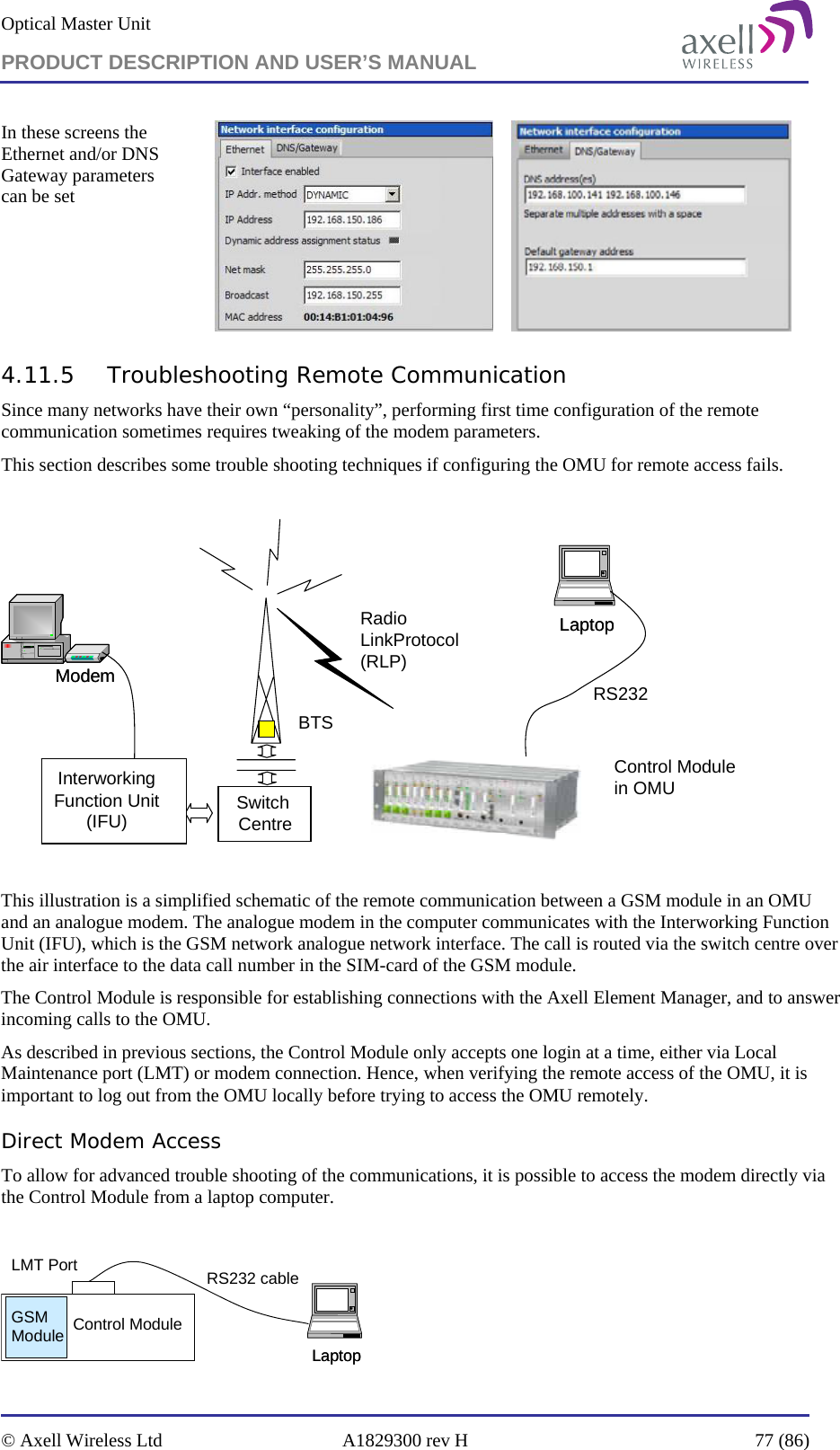
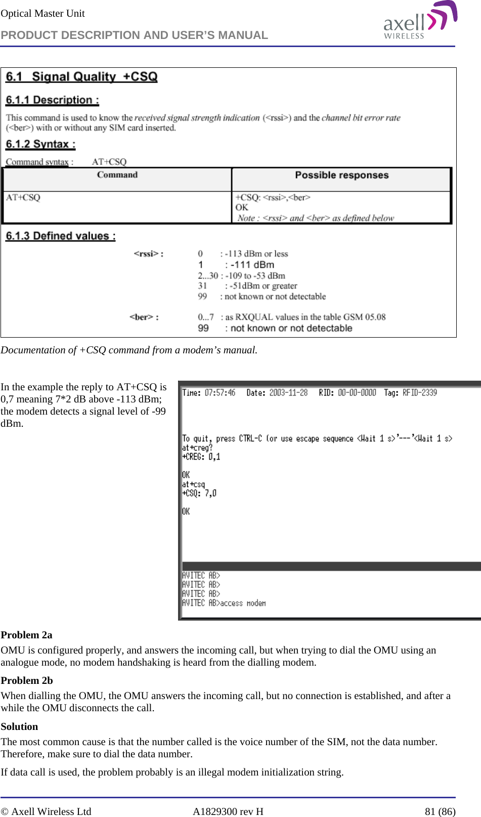


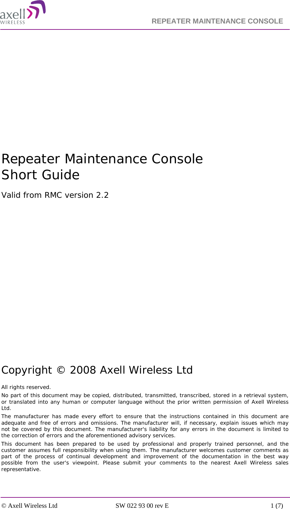


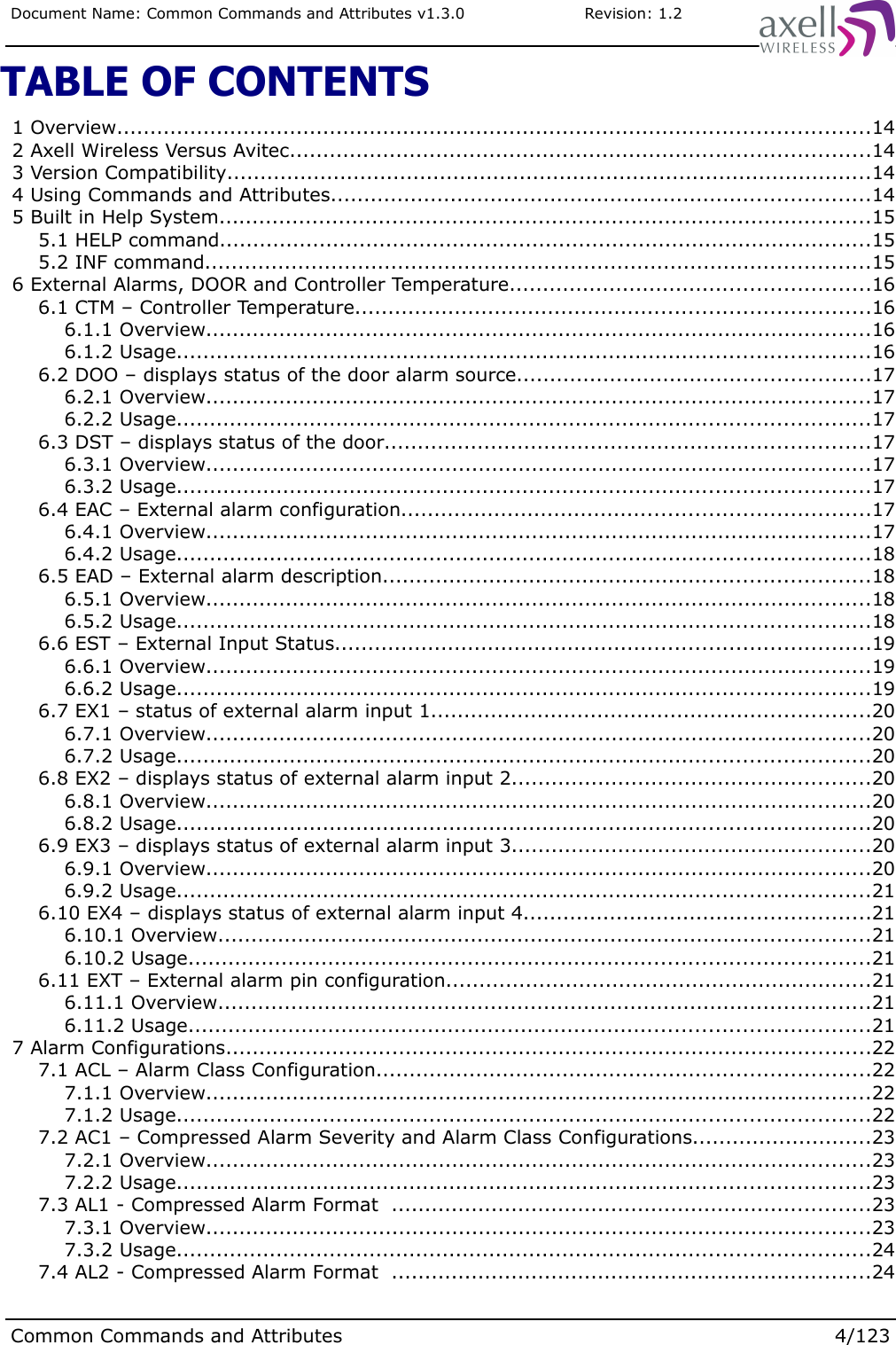
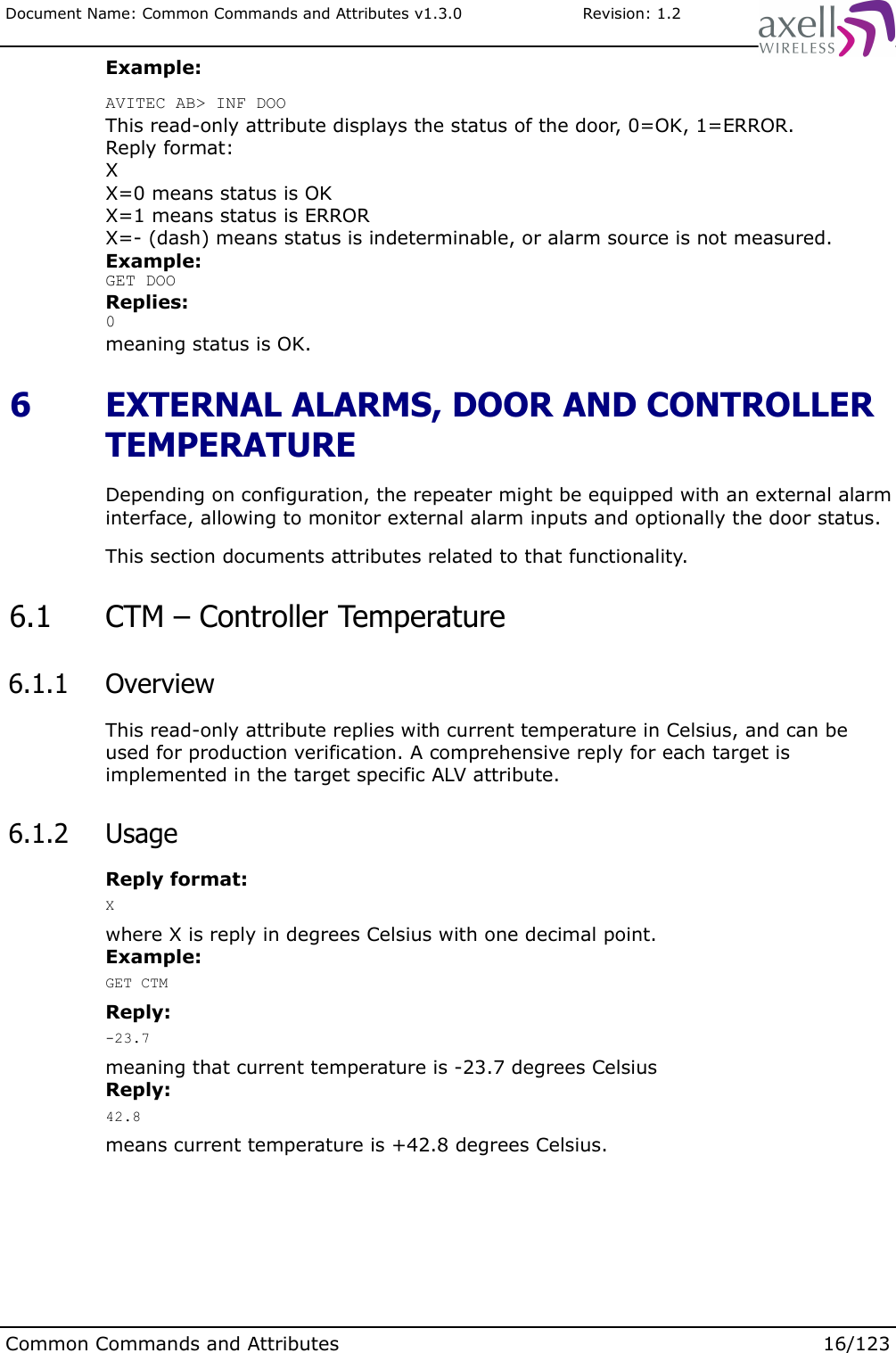
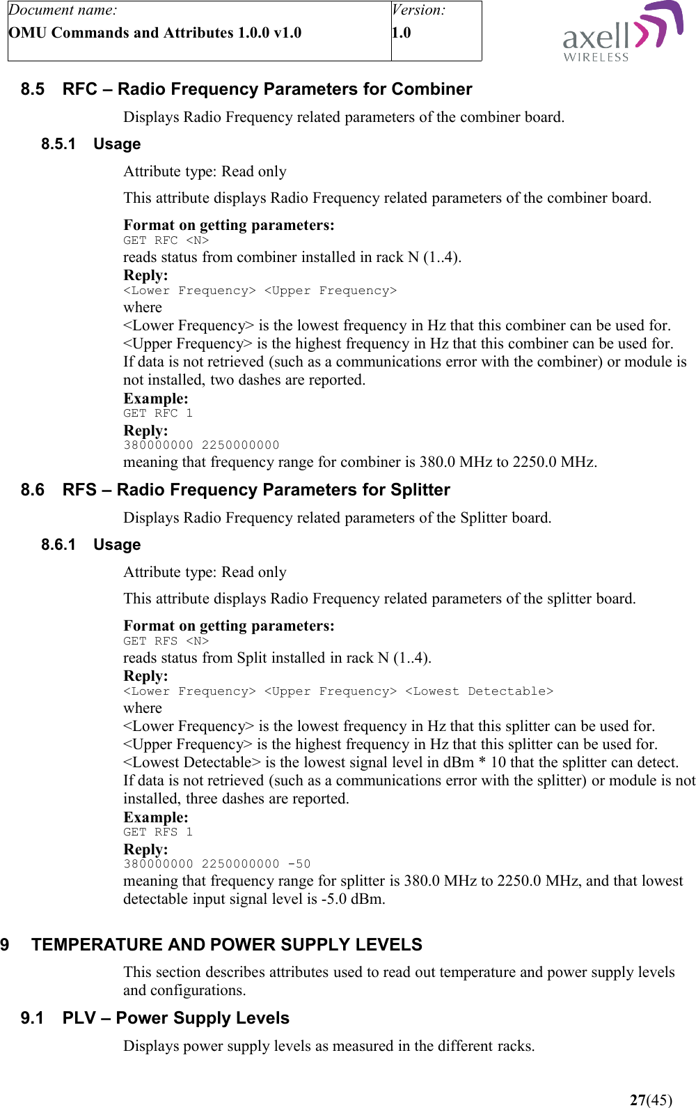
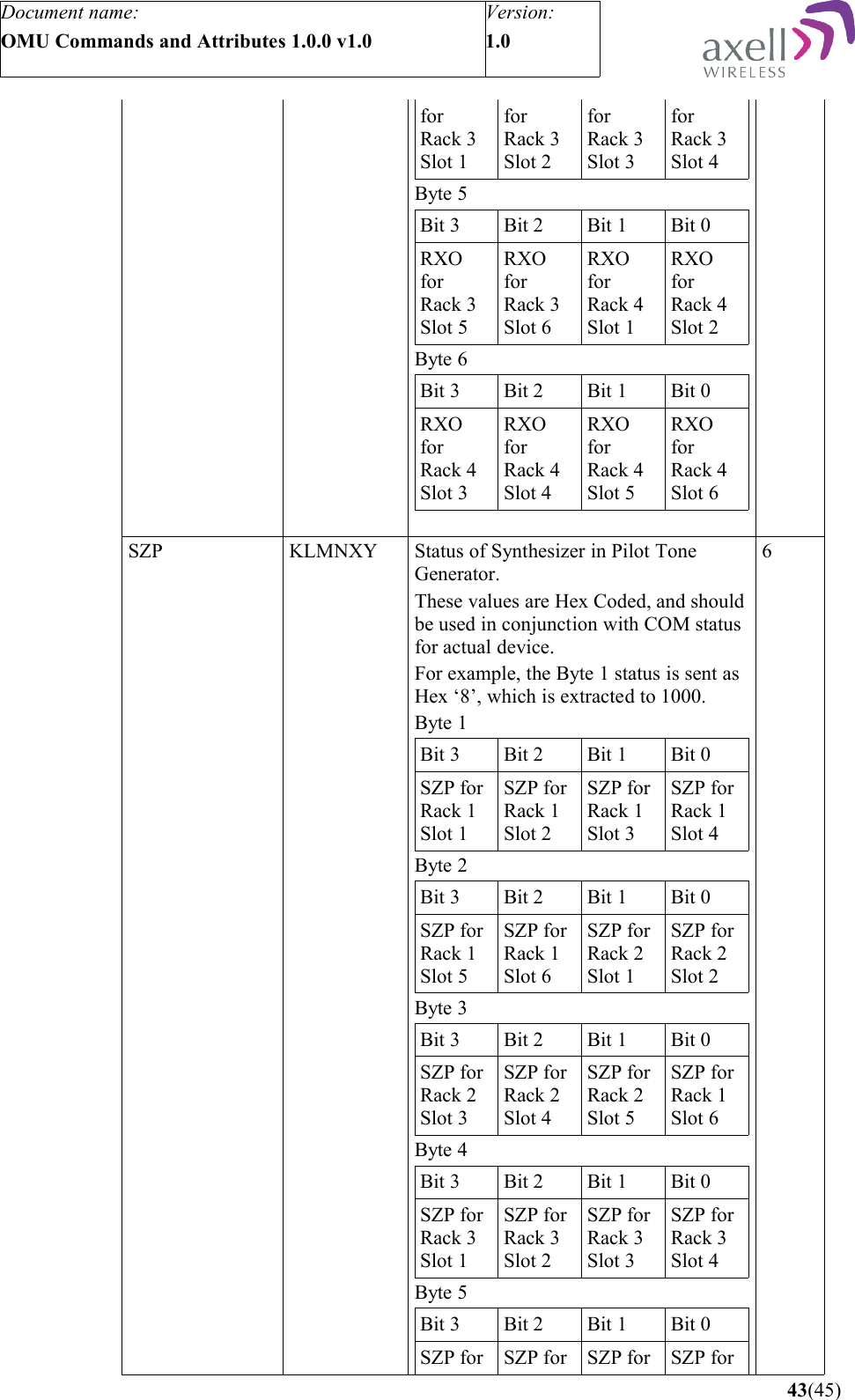
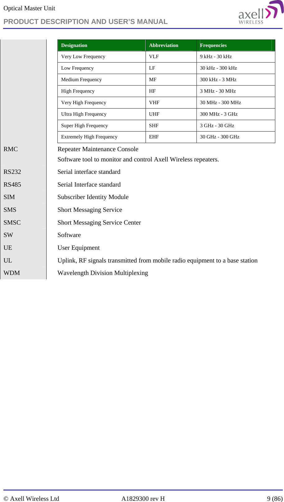
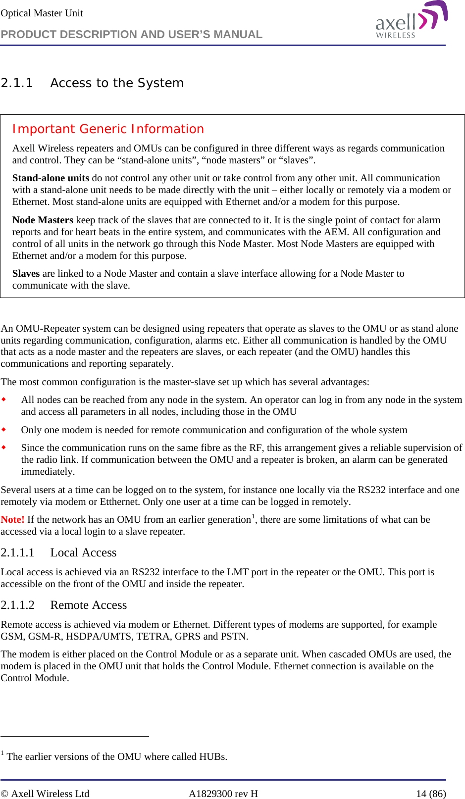
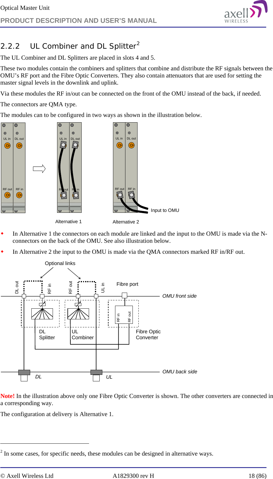
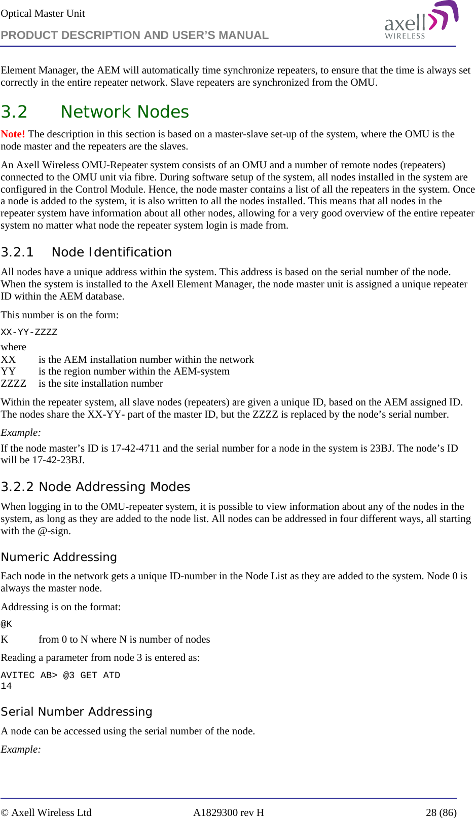
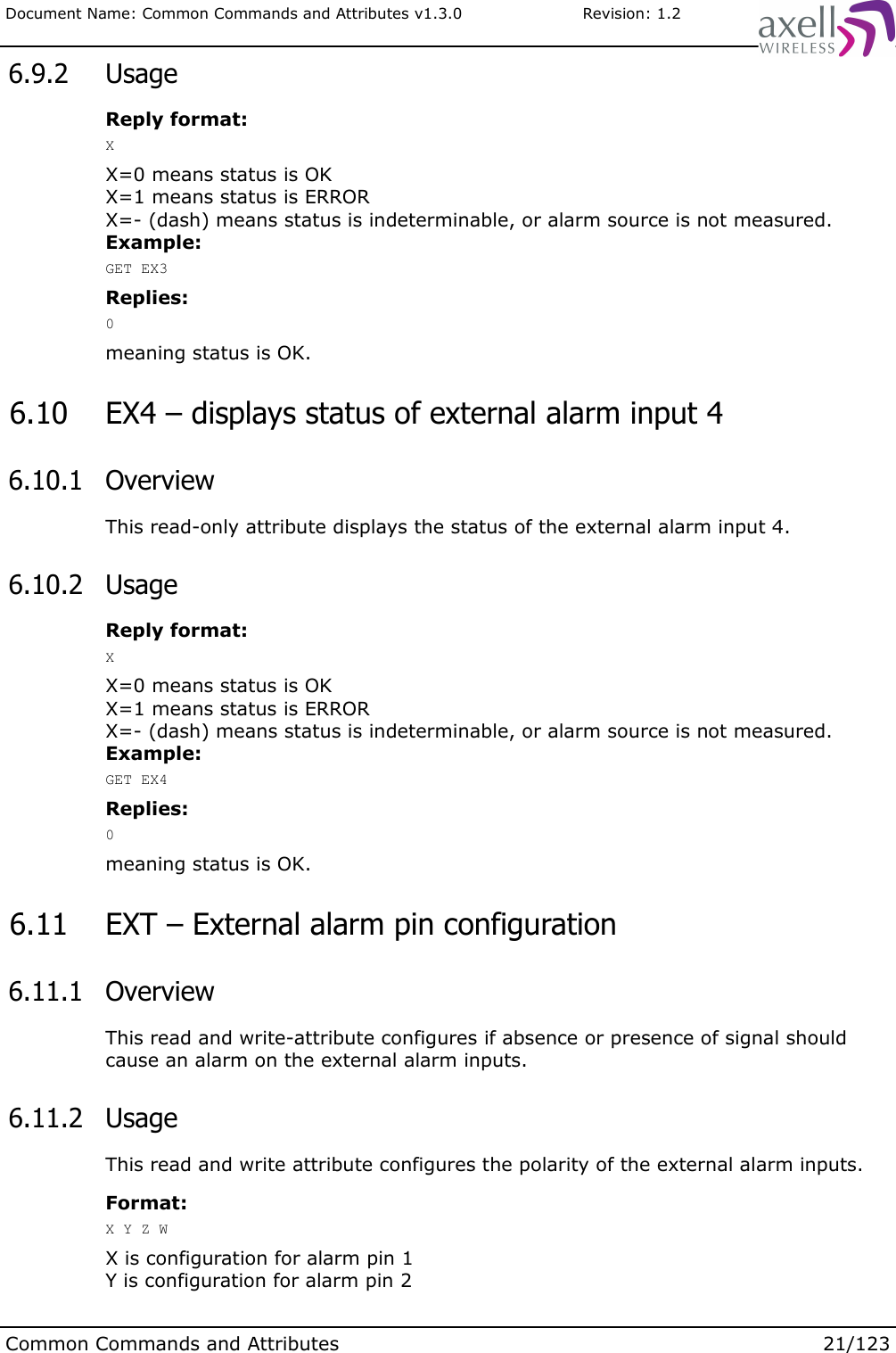
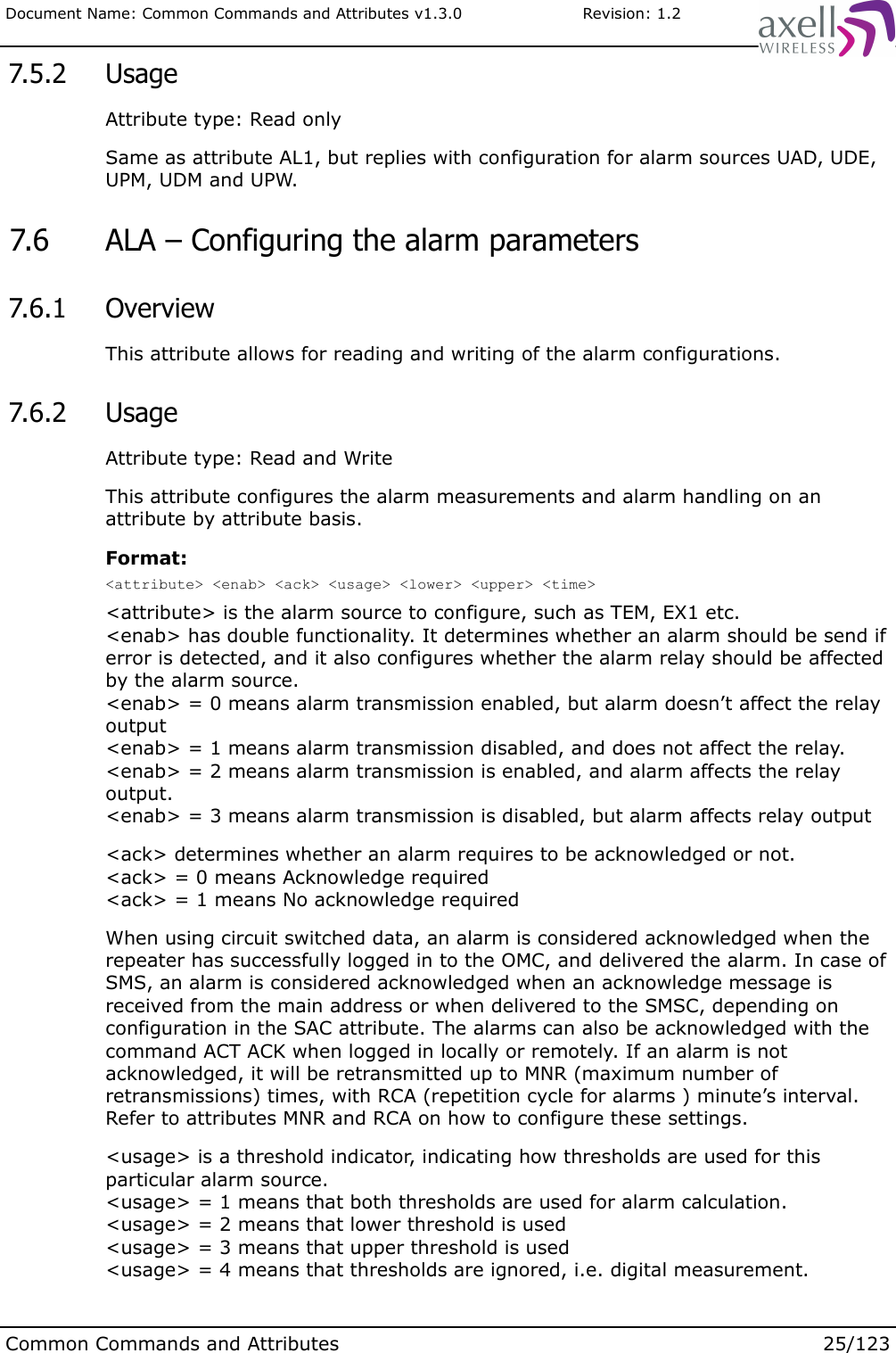
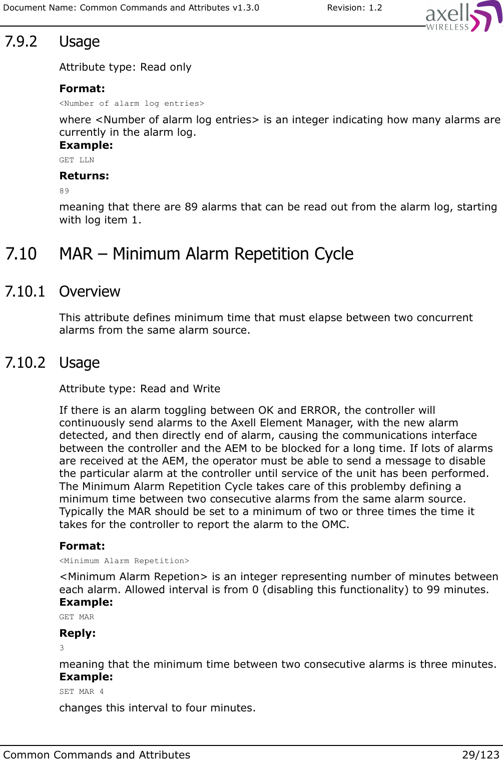
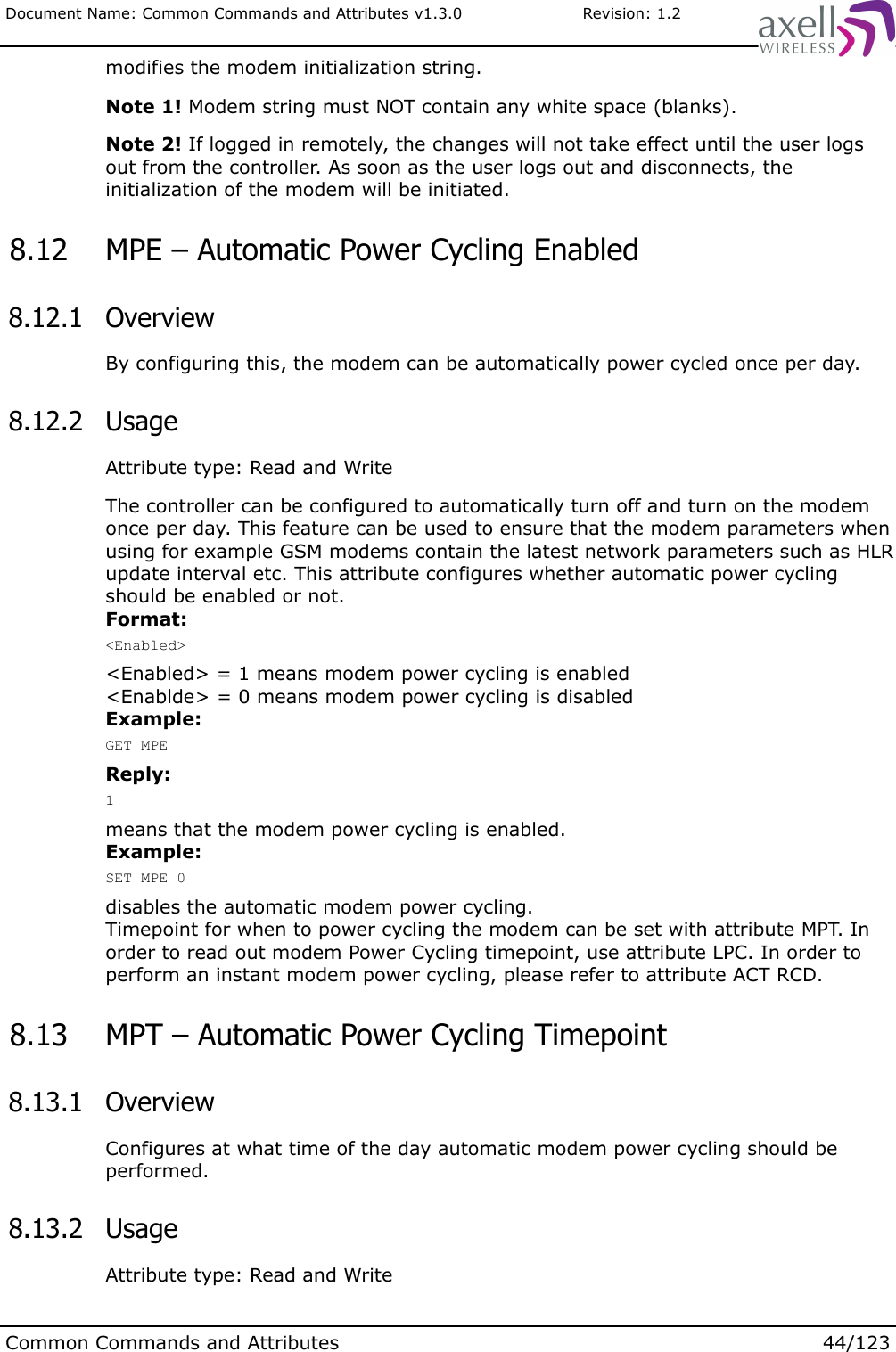
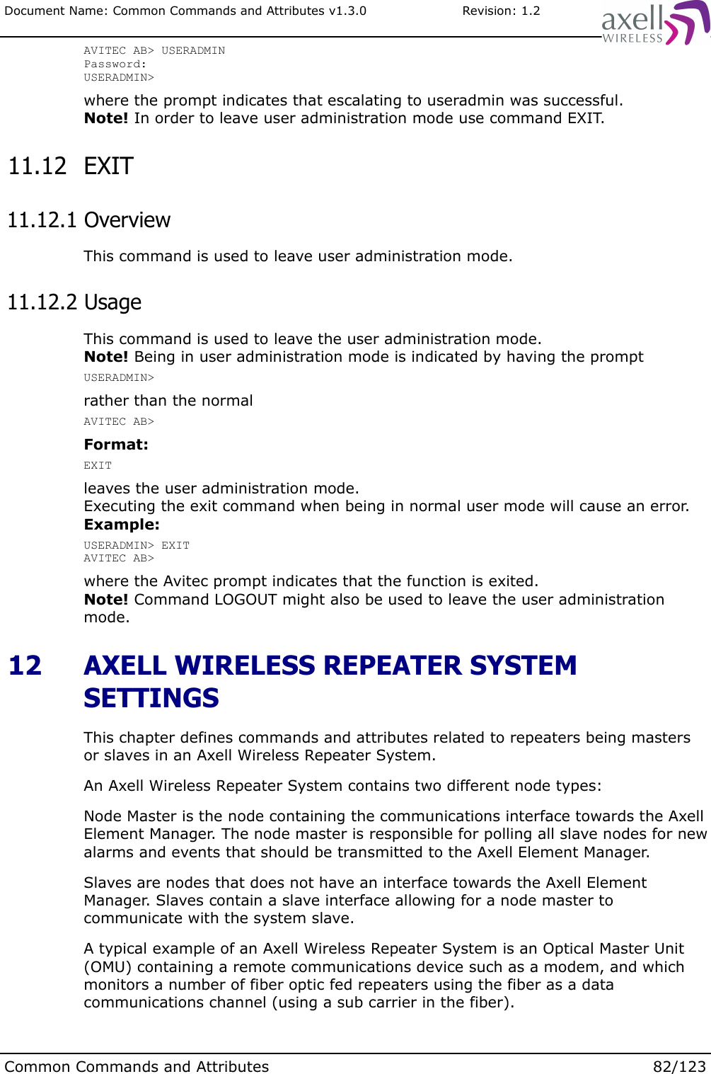
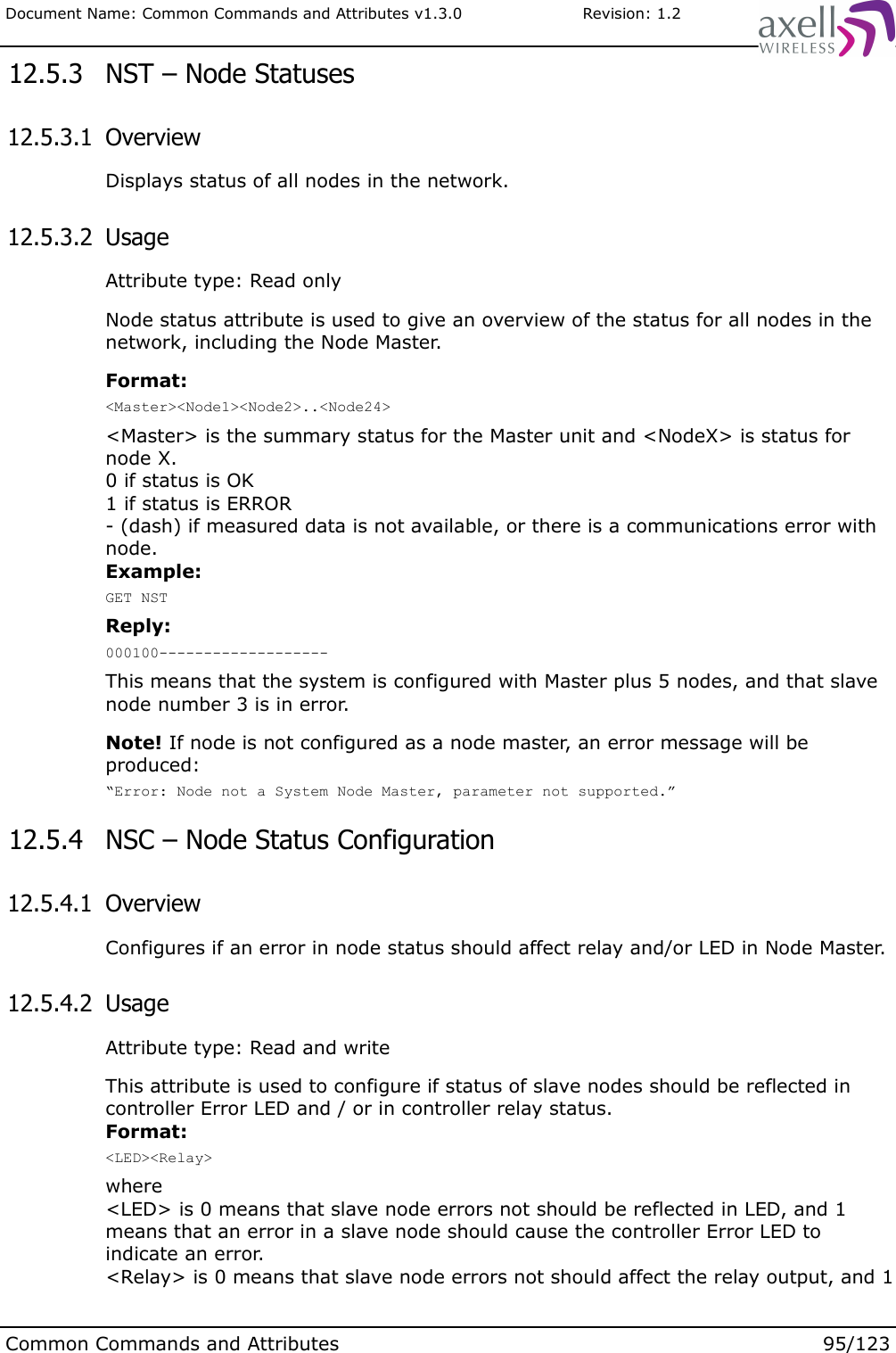
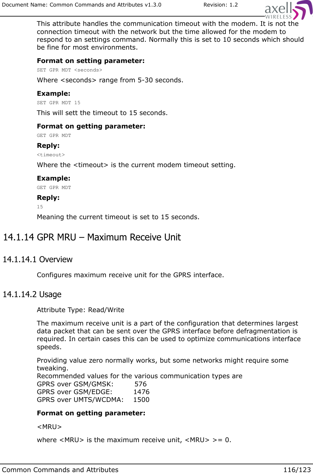
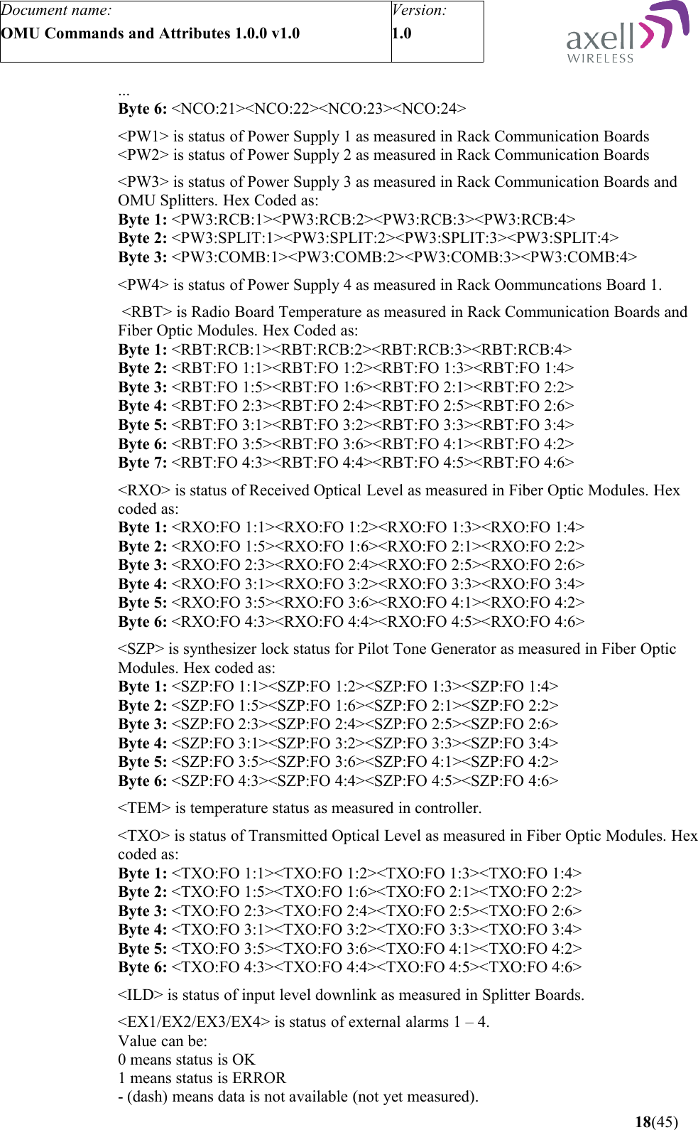
![Document Name: Common Commands and Attributes v1.3.0 Revision: 1.2Format on getting parameter:GET EAD Xwhere X indicates the alarm description for external pin 1,2, 3 or 4.Example:GET EAD 3Replies:UPS Power Failuremeaning that external alarm 3 description is “UPS POWER FAILURE”.Format on setting parameter:SET EAD X [Alarm Pin Description]where X indicates the alarm description for external pin 1,2, 3 or 4.[Alarm Pin Description] is the actual description for this alarm source. Maximum length of string is 35 characters including any spaces.Example:SET EAD 4 Radio Hut Doorsets the alarm description for external alarm pin 4 to Radio Hut DoorNote! Any extra spaces between words will be removed, ensuring that only one space separates each word in the alarm pin description. If extra spaces are required between words, the description can be put in double quotes, such as SET EAD 2 “Description with many spaces” 6.6 EST – External Input Status 6.6.1 OverviewThis read-only attribute displays the current status of the external alarm input pins, and is mainly used for advanced trouble shooting and production test. The actual levels are displayed without any mapping to the EXT attribute. 6.6.2 UsageFormat:X Y Z WwhereX is level on external alarm pin 1.Y is level on external alarm pin 2.Z is level on external alarm pin 3.W is level on external alarm pin 4.Reply = 0 means input on pin is 0, while 1 means input is high.Example:GET ESTReply:0 1 1 0means that pins 3 and 4 have high inputs while pin 1 and 4 have low inputs.Common Commands and Attributes 19/123](https://usermanual.wiki/PBE-Europe-as-Axell-Wireless/A207SERIES/User-Guide-1216782-Page-113.png)
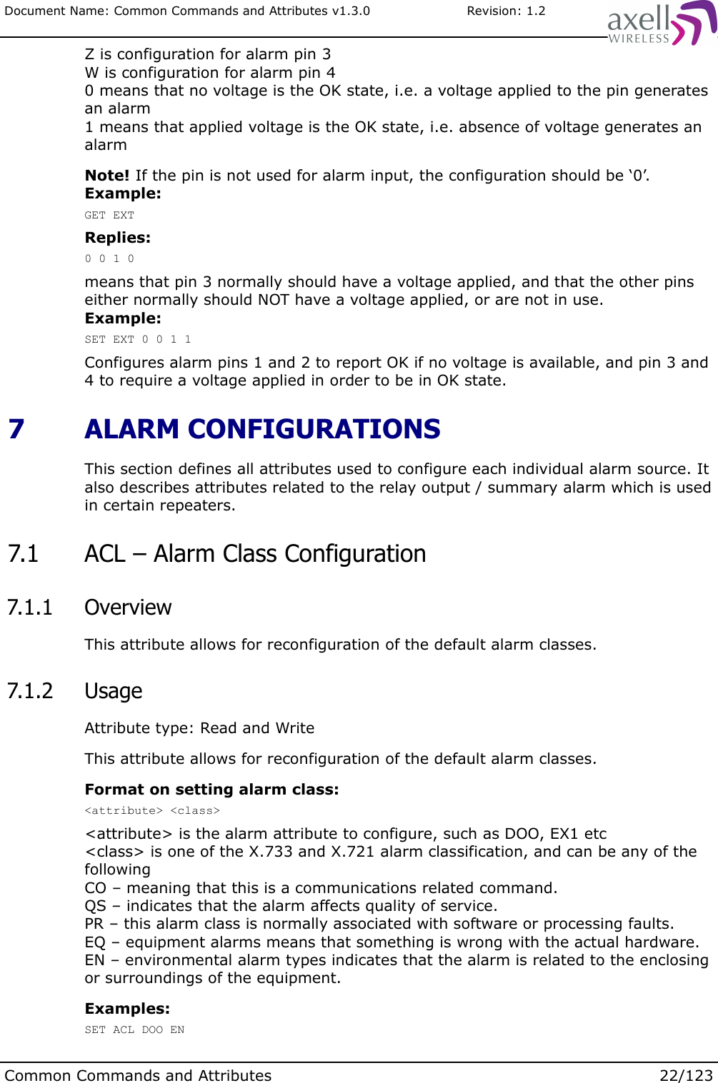
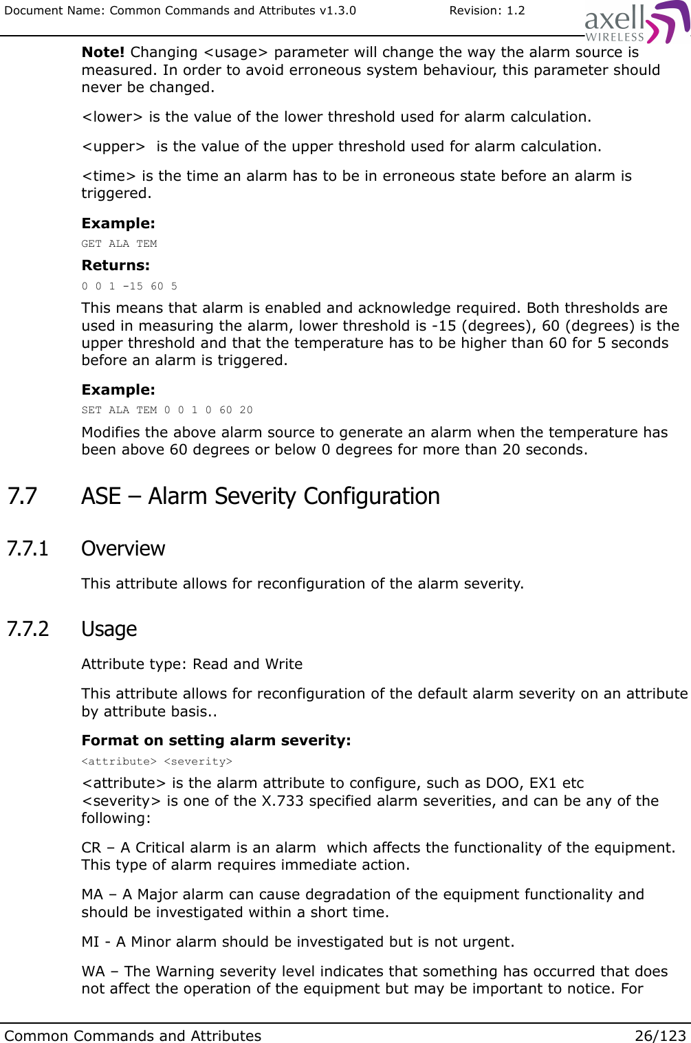
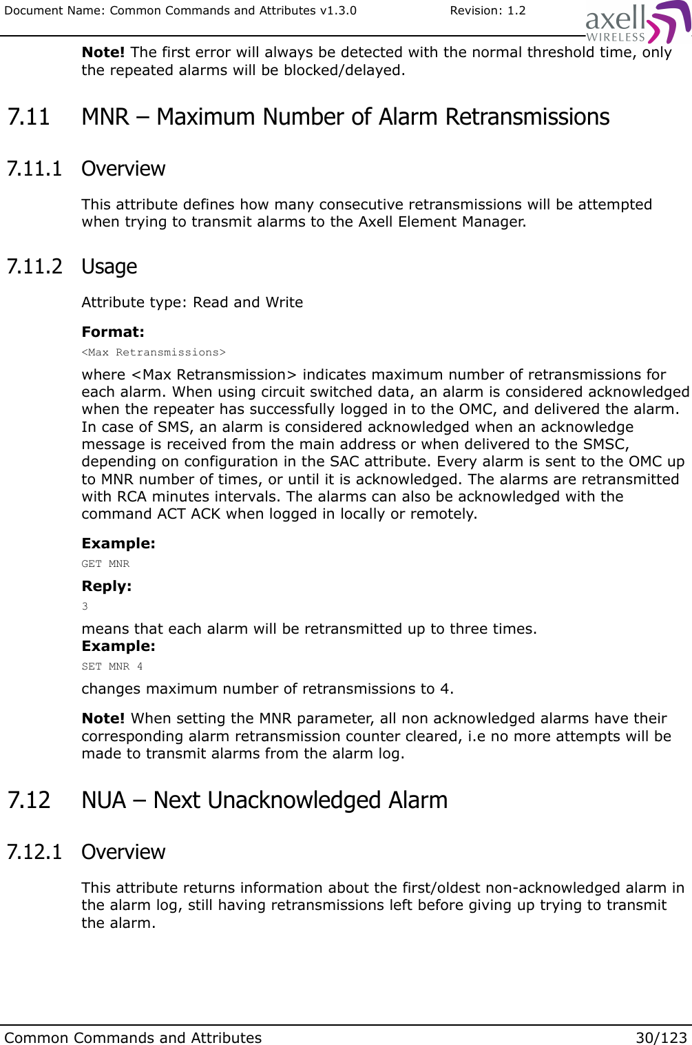
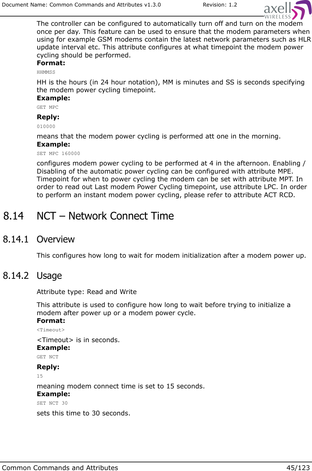
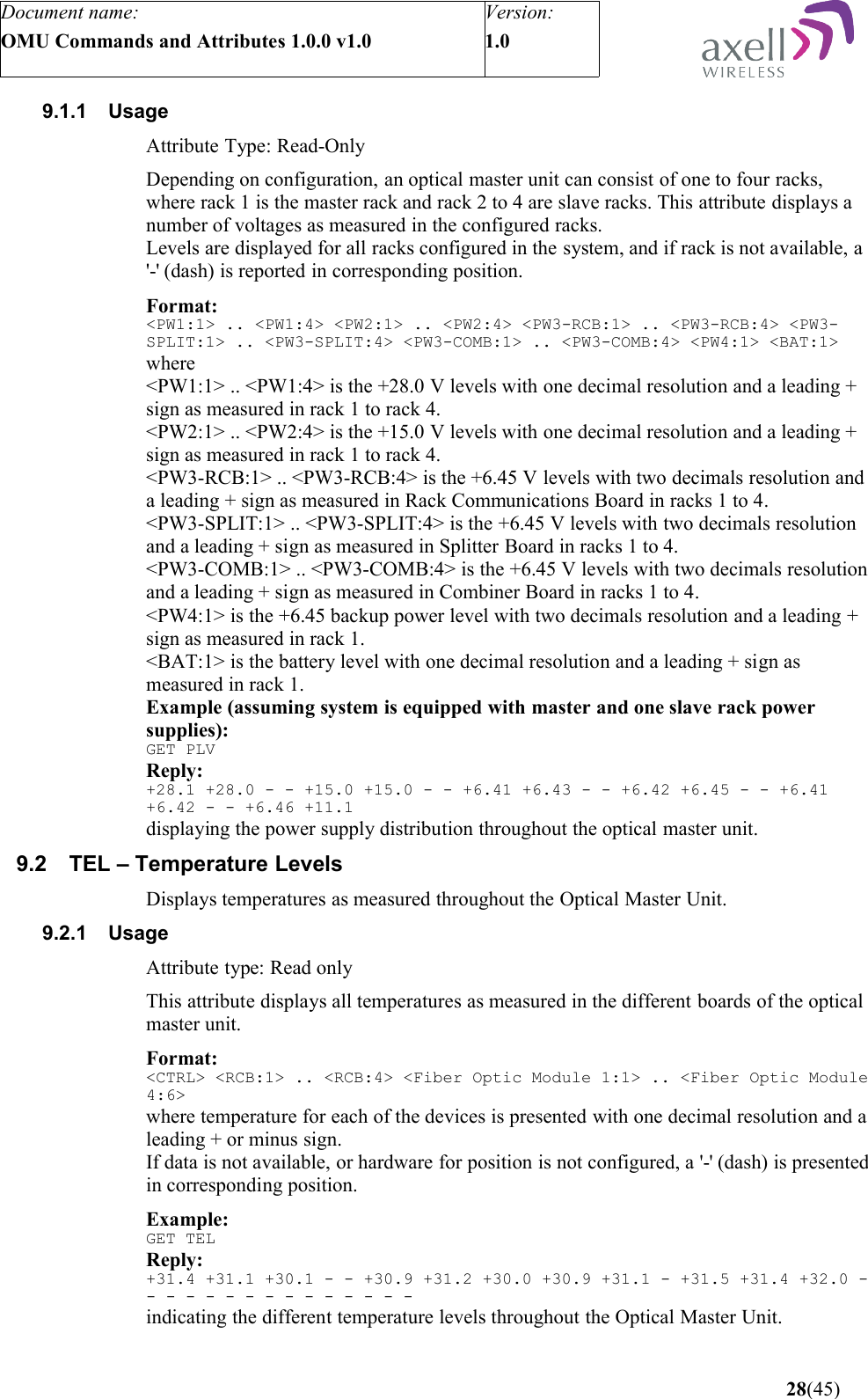
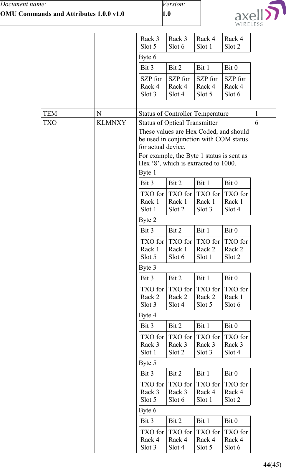
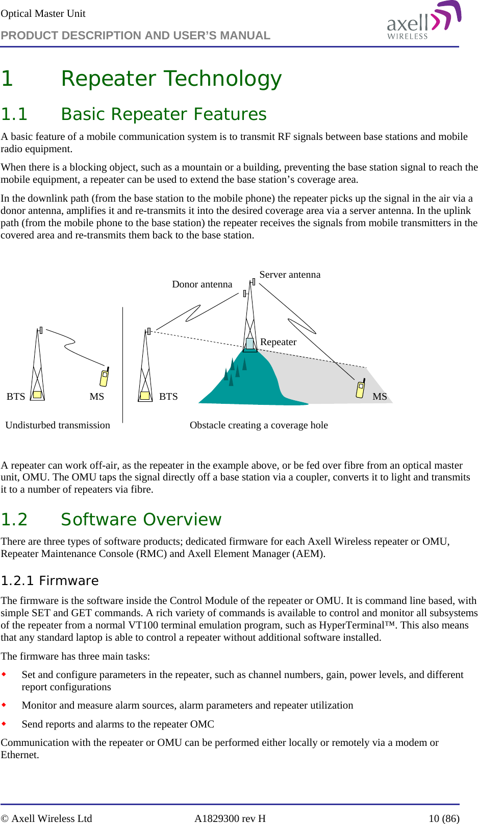
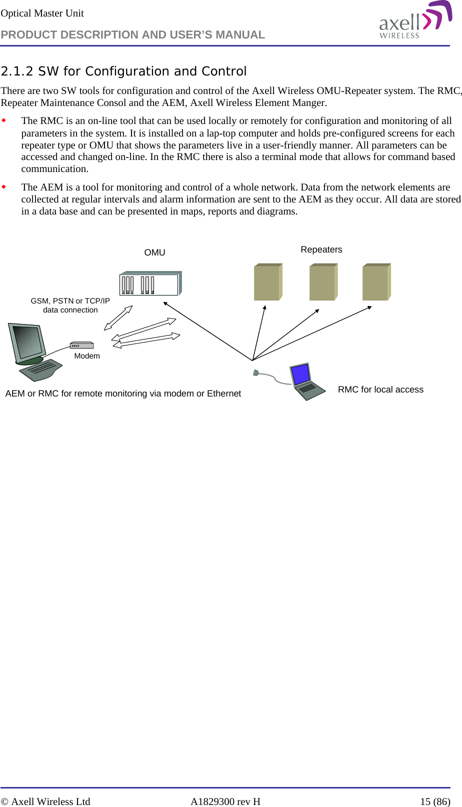
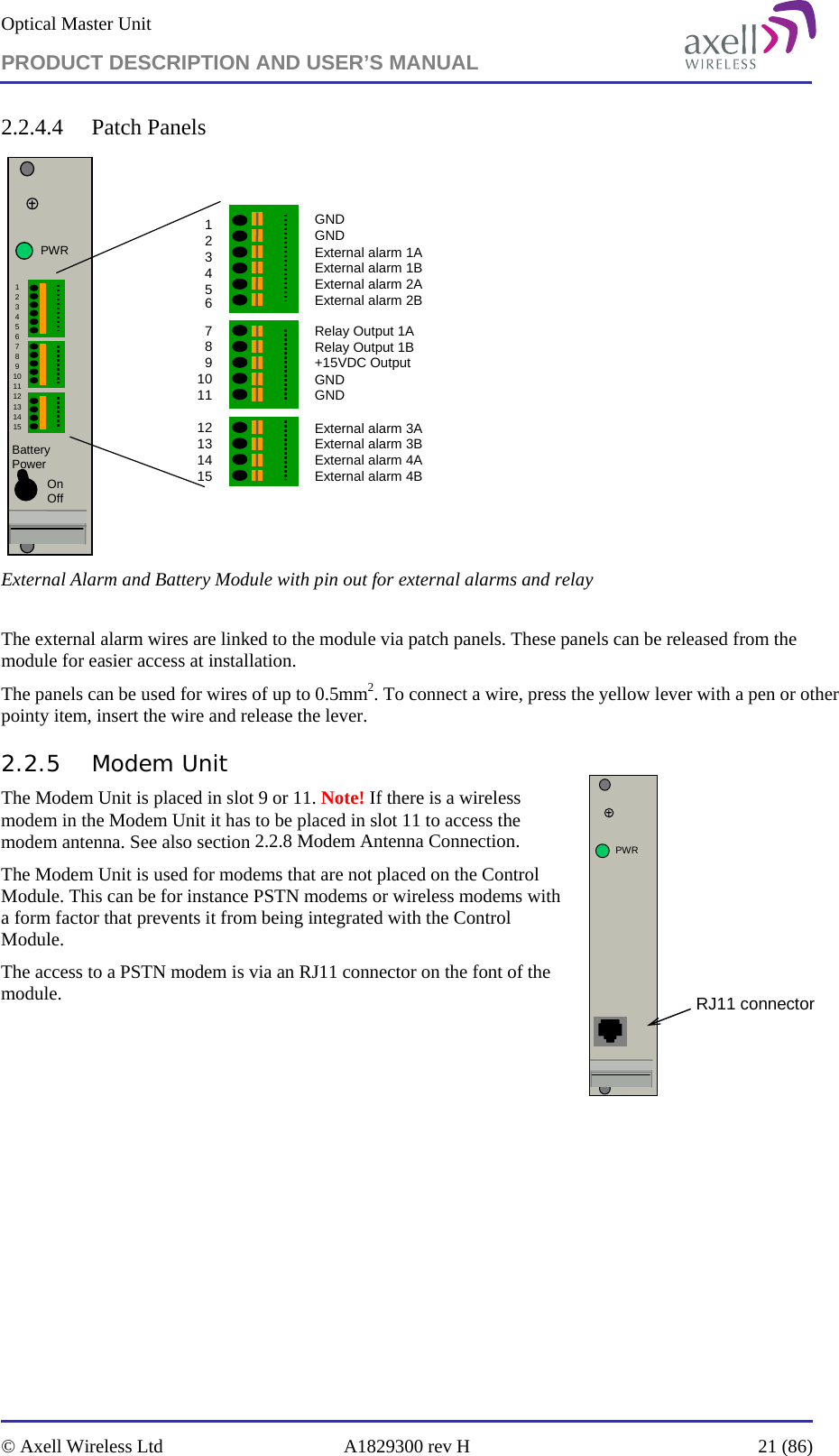
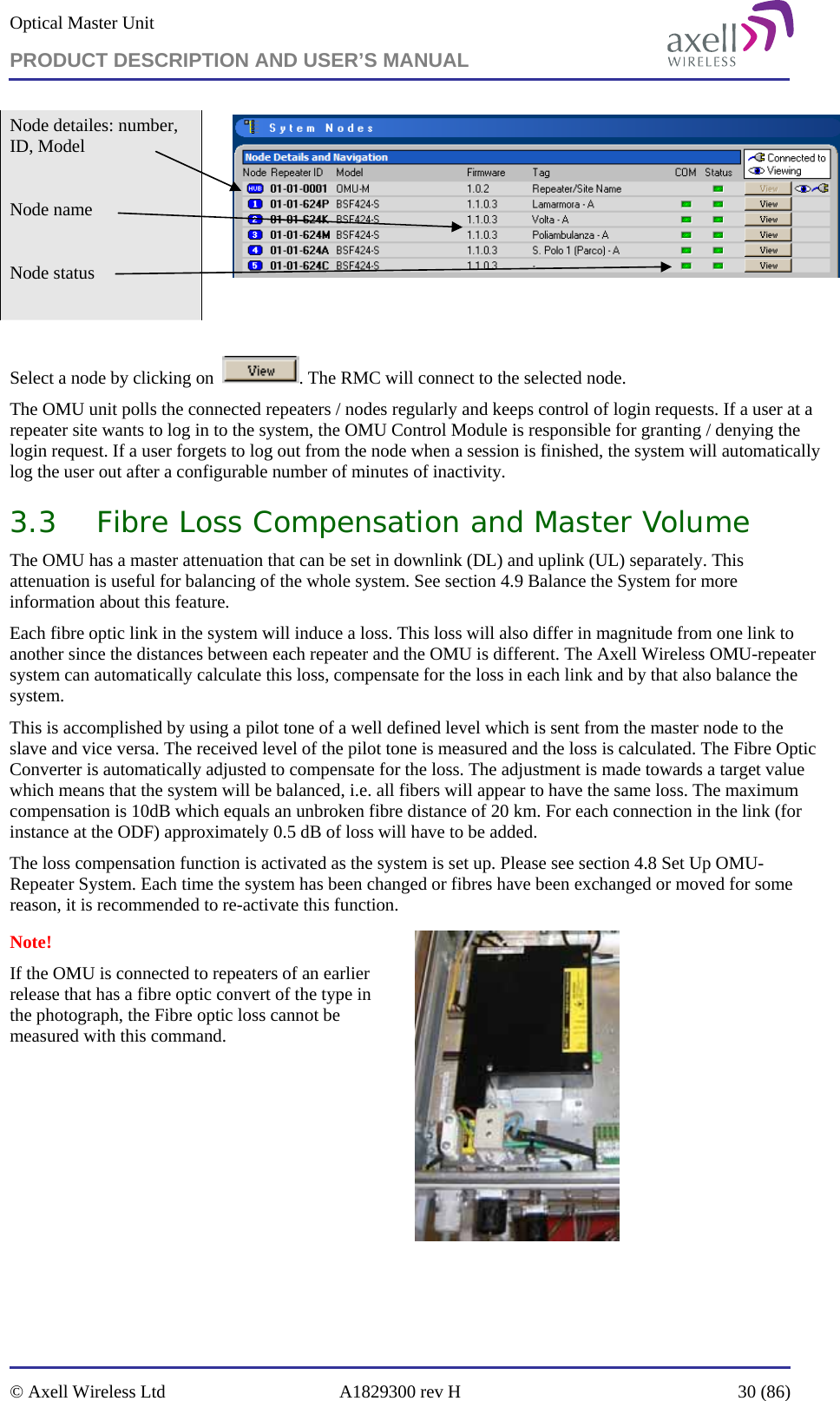
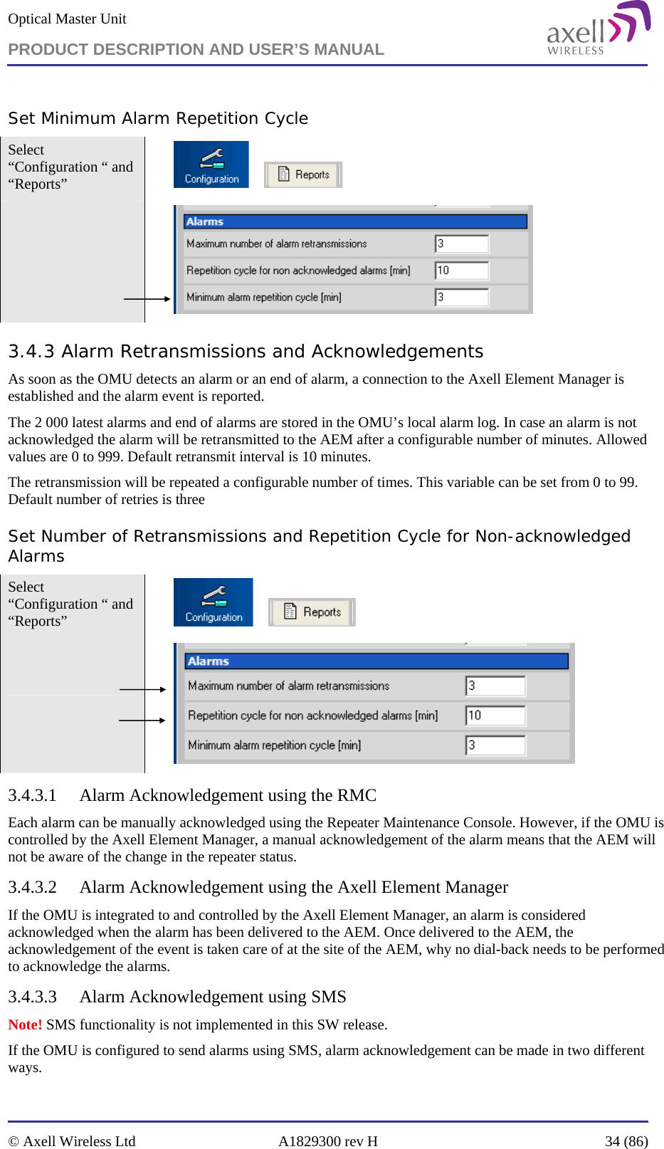
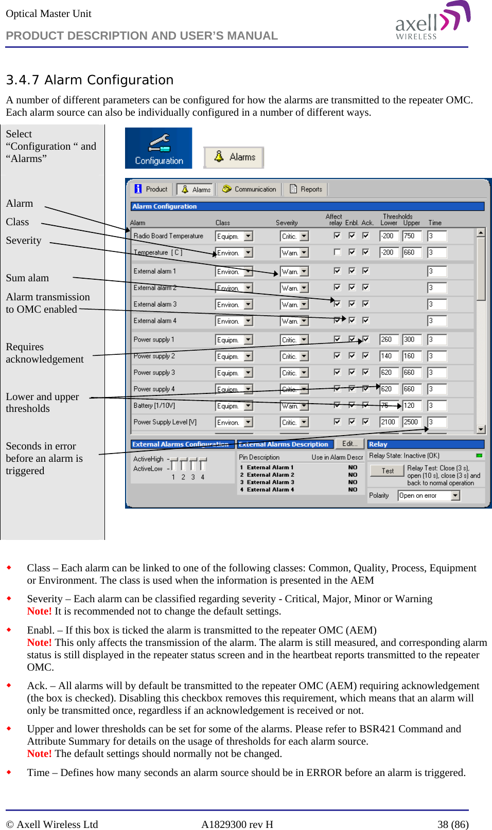
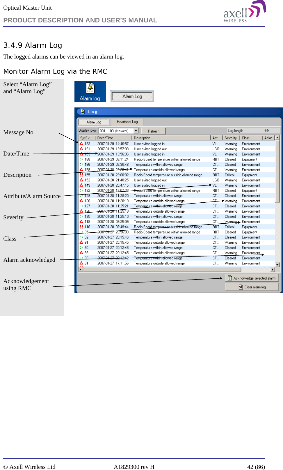
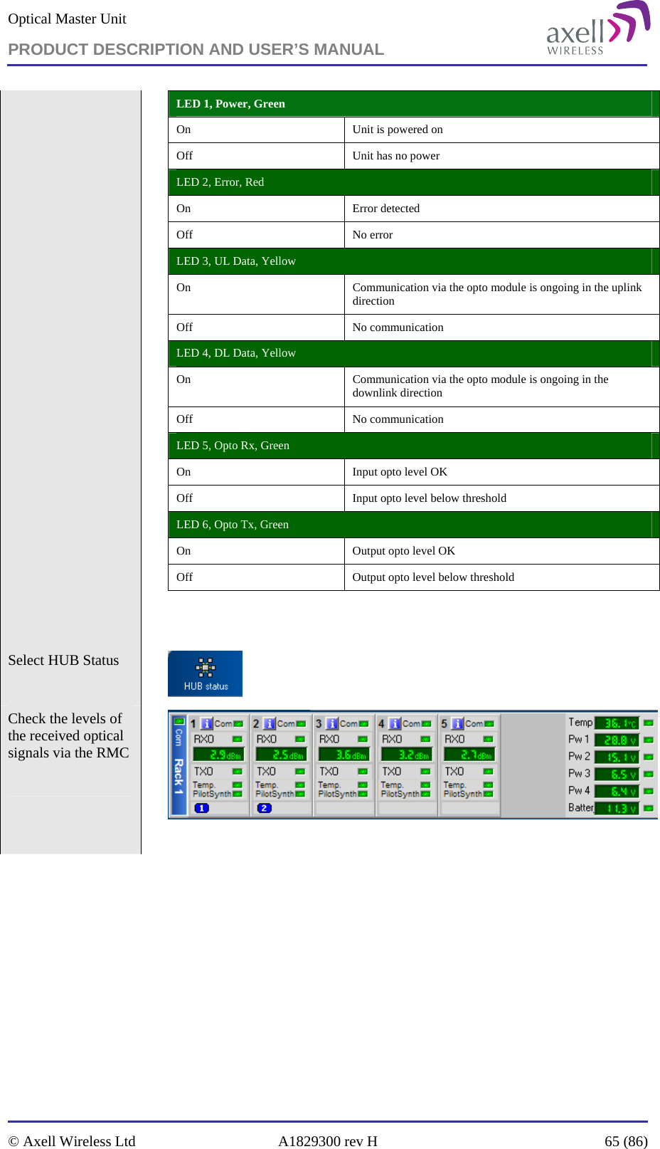
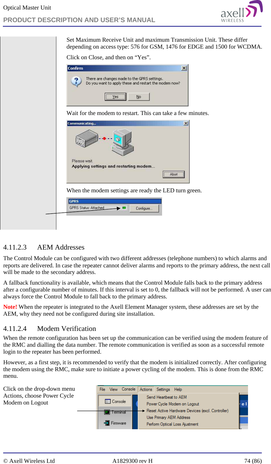
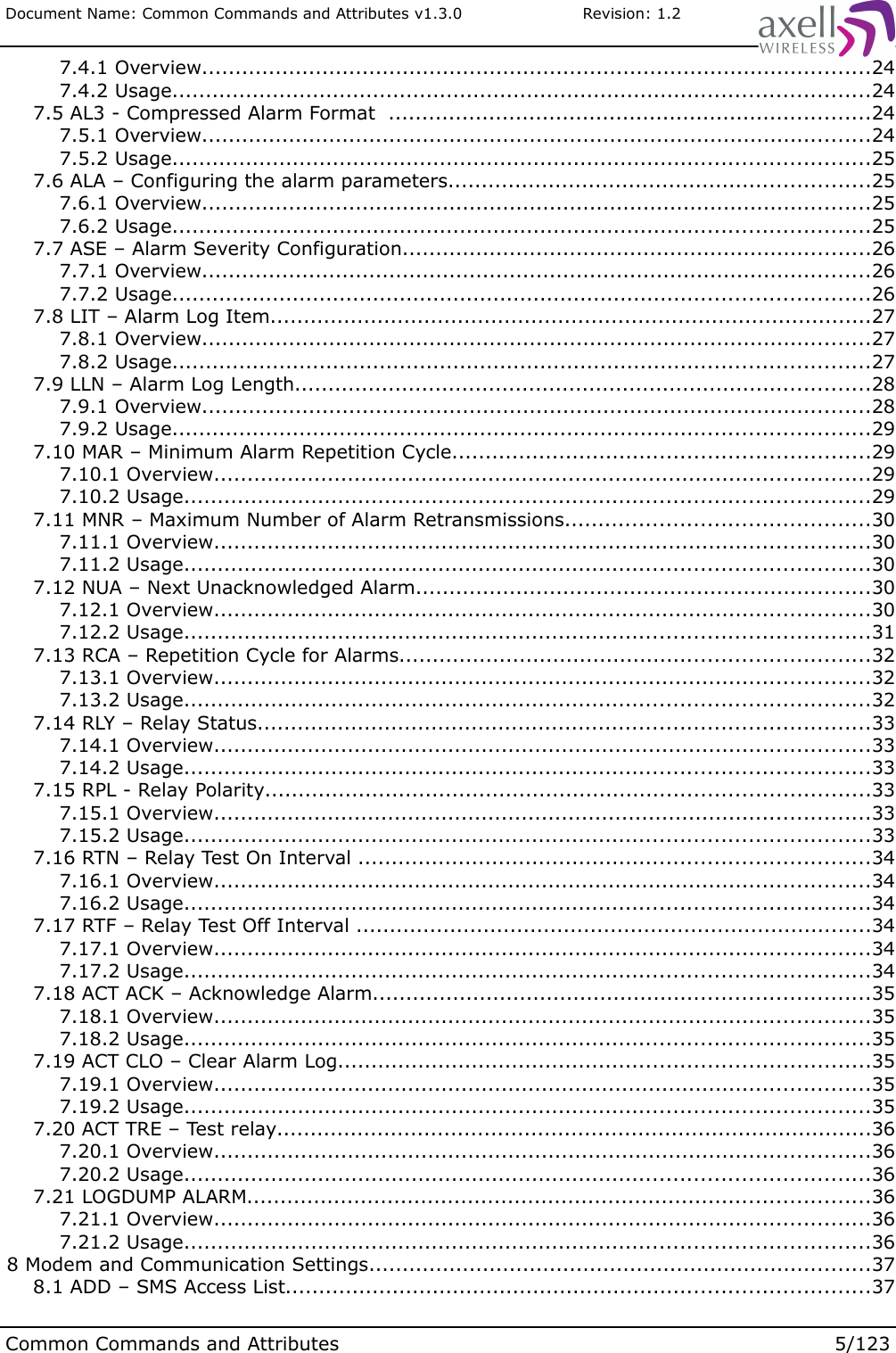
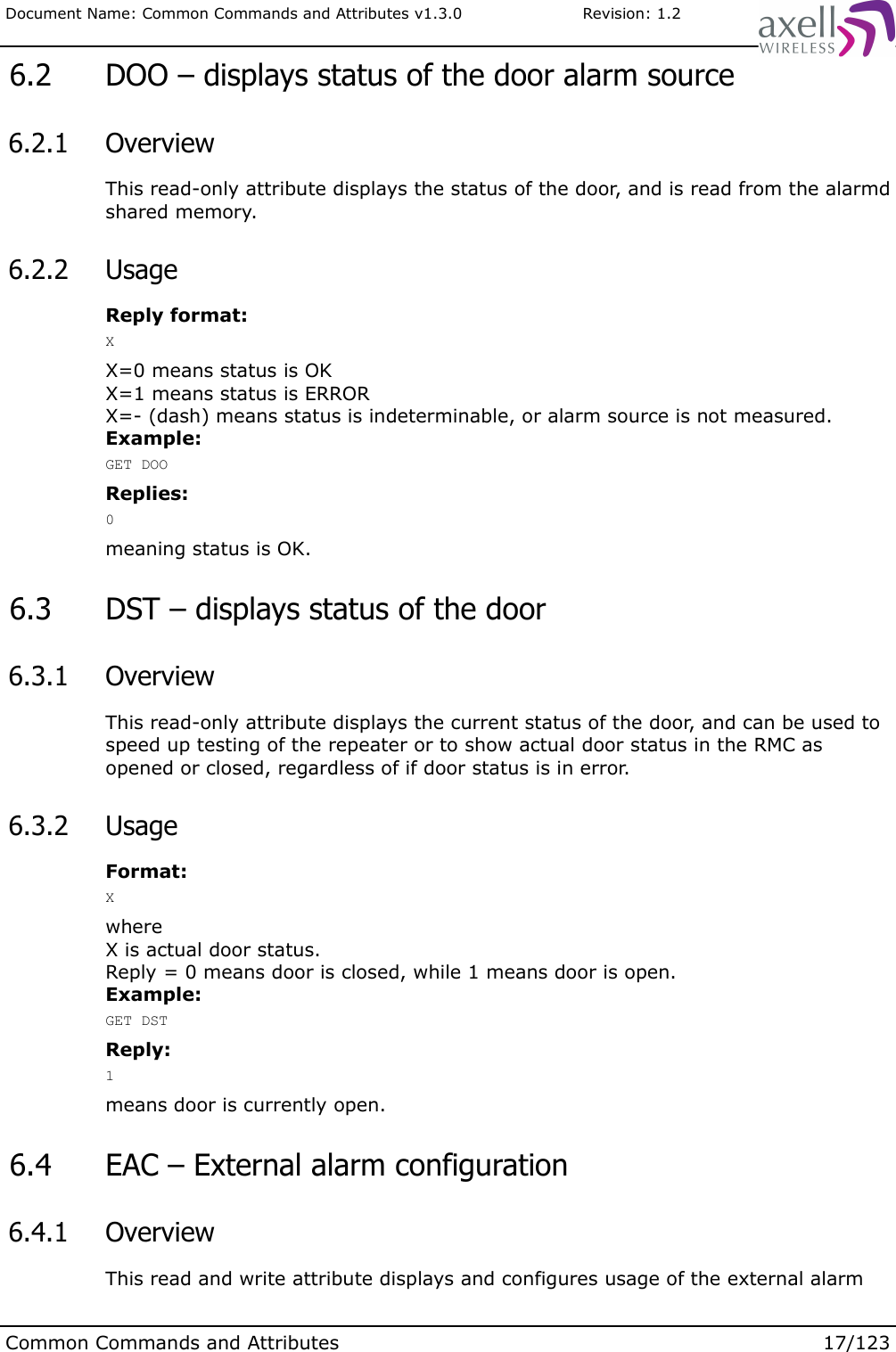
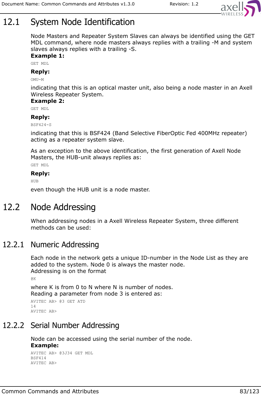
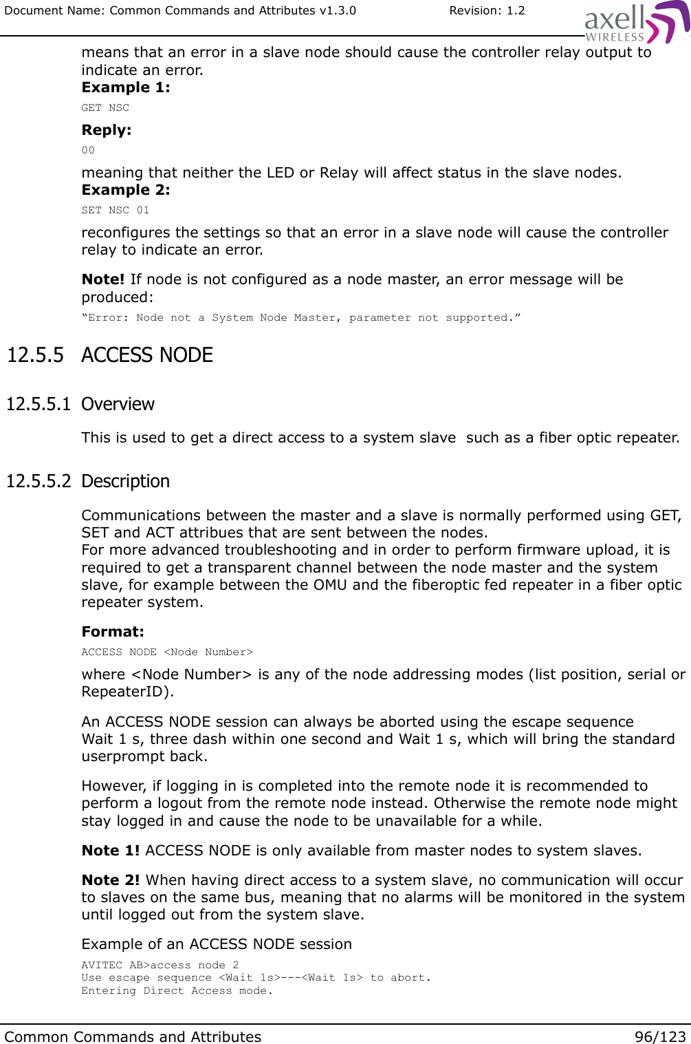
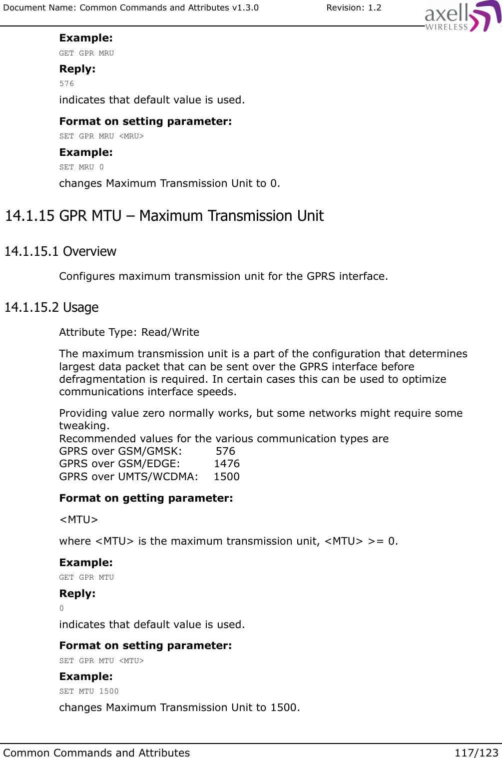
![Document Name: Common Commands and Attributes v1.3.0 Revision: 1.2ACT RCD [Delay]where the optional delay parameters denotes how many seconds from entering the command the modem should be power cycled. If Delay is left out, an immediate power cycling of the modem will be performed (assuming local login).Example:ACT RCDwill, if logged in locally, perform an immediate power cycling of the modem.Note! The controller can also be configured to automatically turn off and turn on the modem once per day. This feature can be used to ensure that the modem parameters when using for example GSM modems contain the latest network parameters such as HLR update interval etc. Attribute MPE is used to configure if automatic modem power cycling should be enabled. Time point for when to power cycling the modem can be set with attribute MPT. In order to read out Last modem Power Cycling time point, use attribute LPC. 8.26 ACT UPA – Use Primary Address 8.26.1 OverviewThis forces an immediate fall back to dial primary AEM address in case of alarms or reports. 8.26.2 UsageAttribute type: Write-Only ActionThe controller can be configured to use both primary and the backup address (as configured with attribute ASC and SSC) for delivery of alarms and reports to the Axell Element Manager. In case connection to the first address fails, the controller automatically attempts to connect to the secondary address instead. Using the attribute SFT (Secondary fall back Timer) it is possible to configure after how long the controller will go back to the primary address again. By using this attribute it is possible to force an immediate fall back to the primary address again. This can for example be used if the primary address has been down for any reason to force all network elements to go back to primary address again.Format:ACT UPAcauses the immediate fall back to the primary address.Note! Executing this action when controller is already dialing primary address has no effect. 8.27 ACCESS MODEM 8.27.1 OverviewThis command can be used for advanced trouble shooting of the modem configurations.Common Commands and Attributes 52/123](https://usermanual.wiki/PBE-Europe-as-Axell-Wireless/A207SERIES/User-Guide-1216782-Page-146.png)
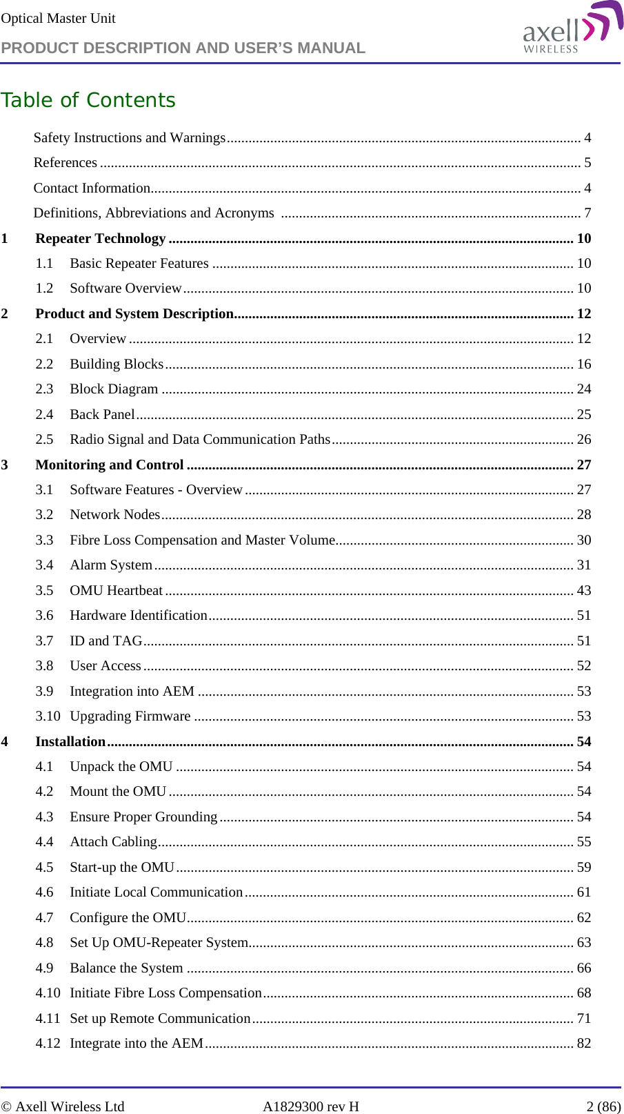
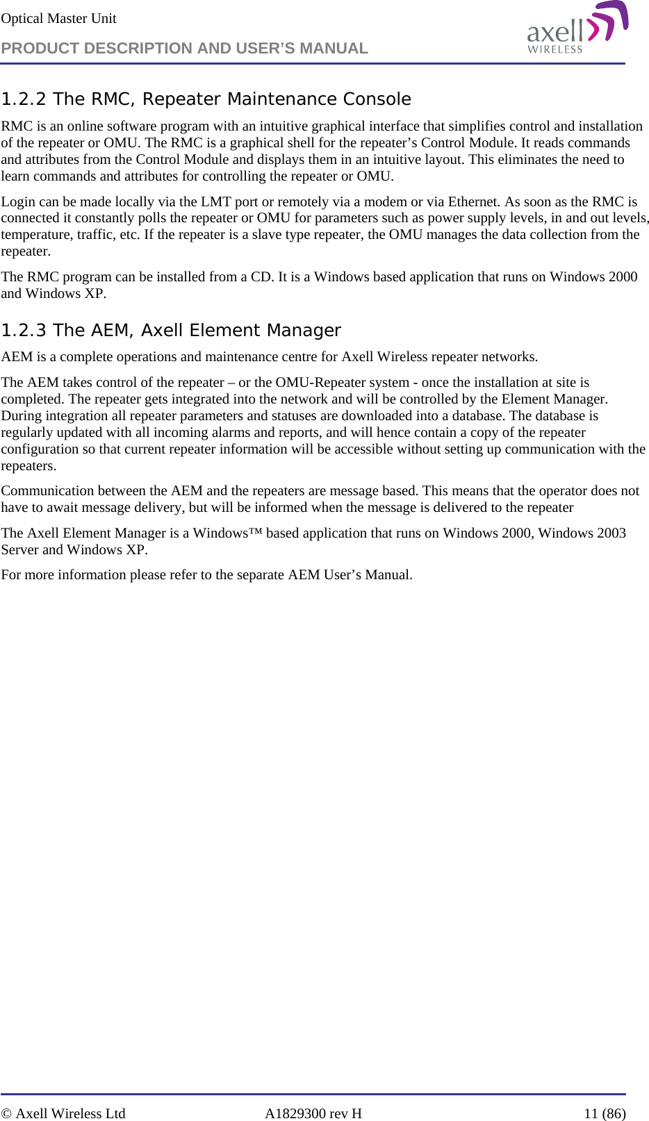
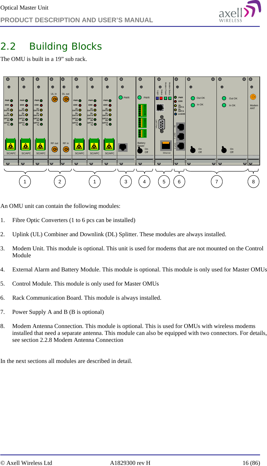
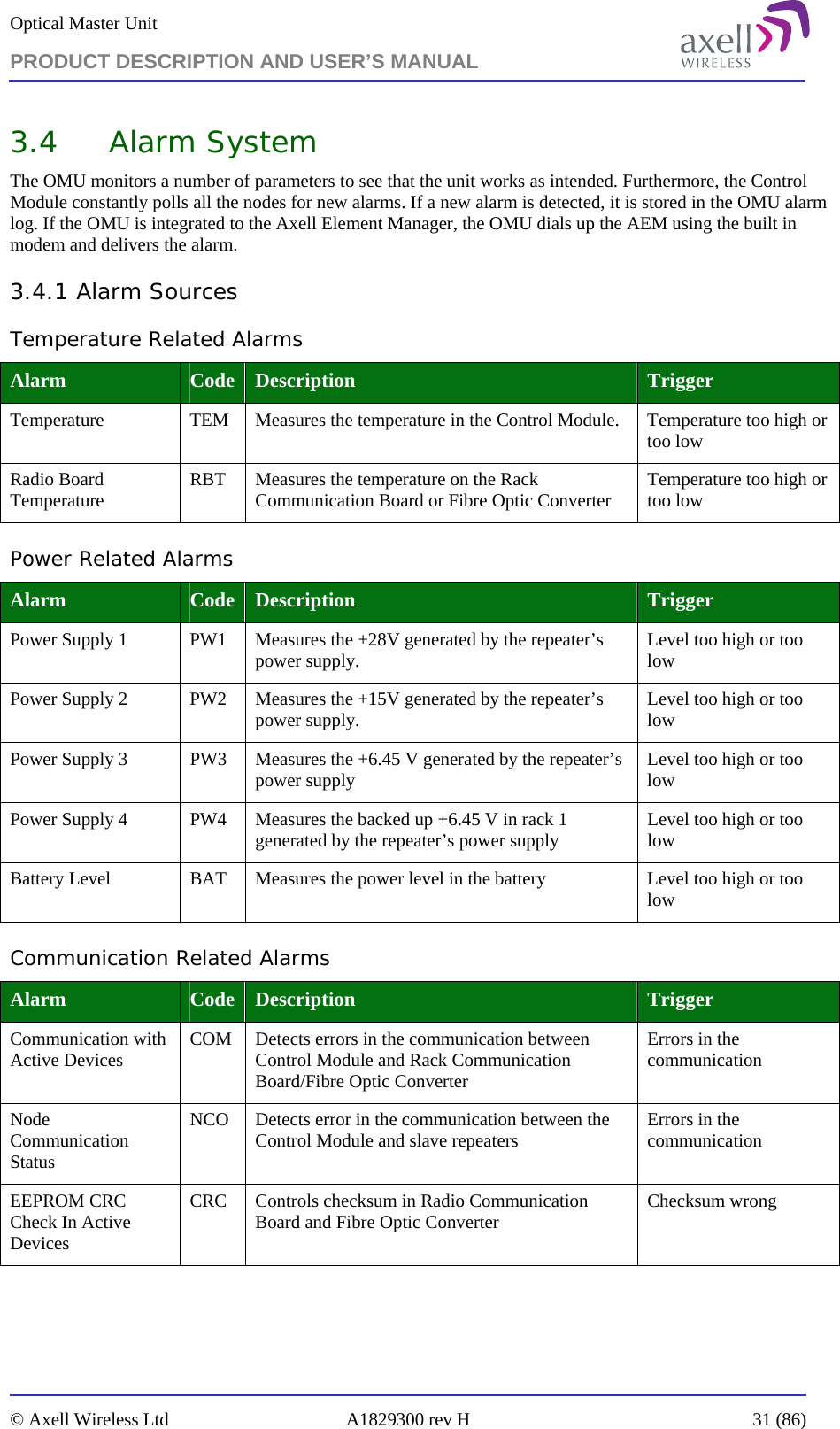
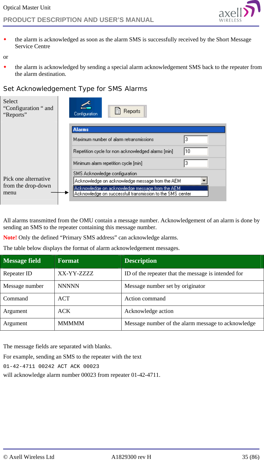
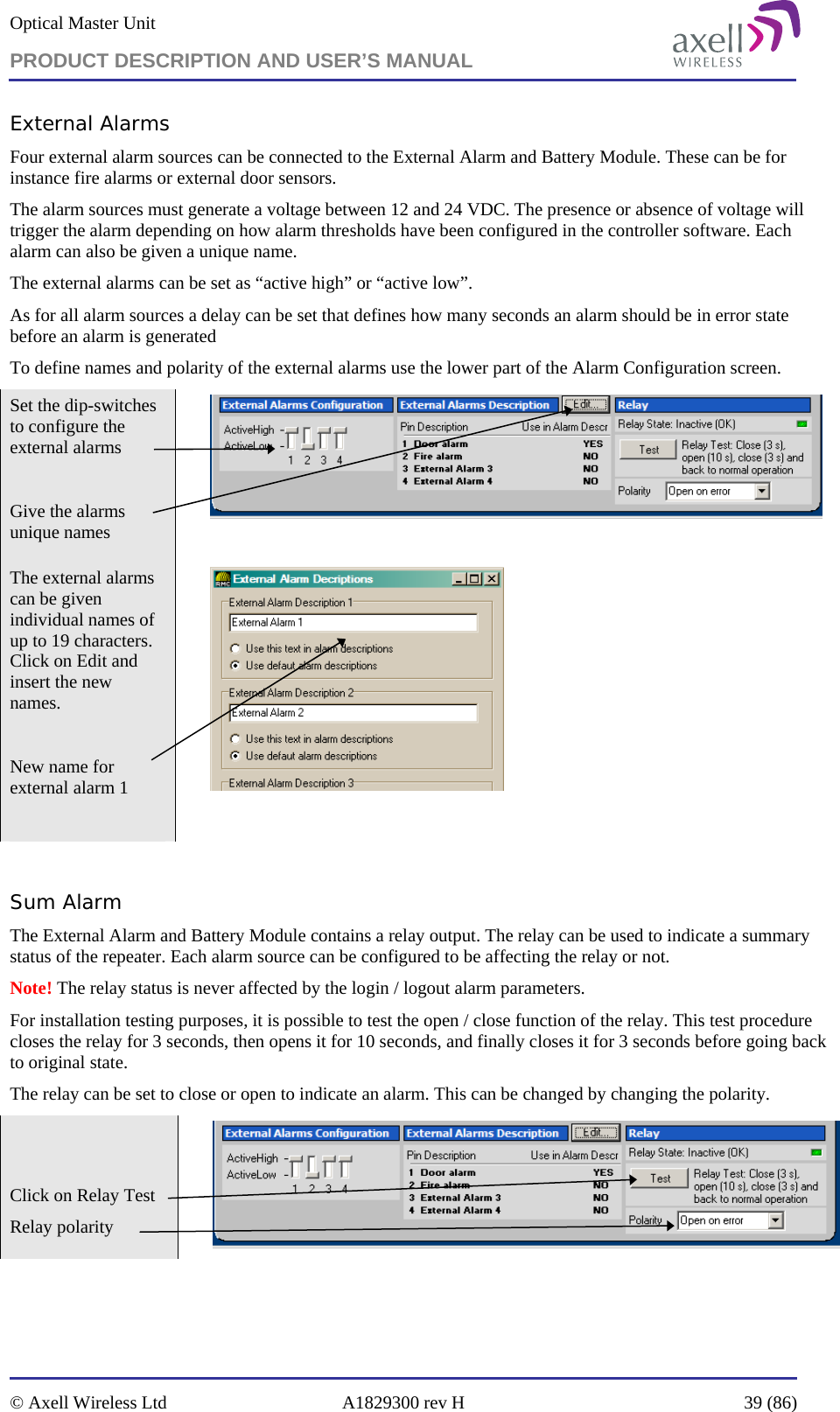
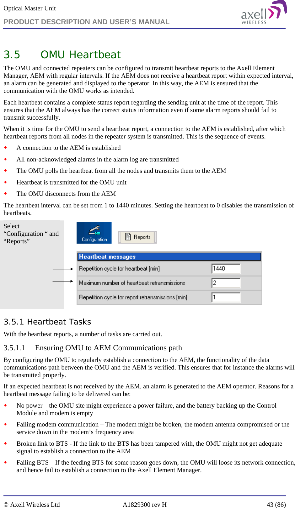
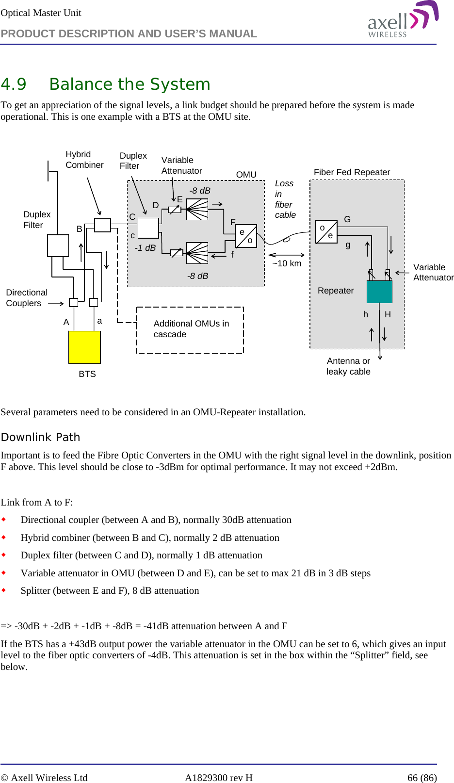
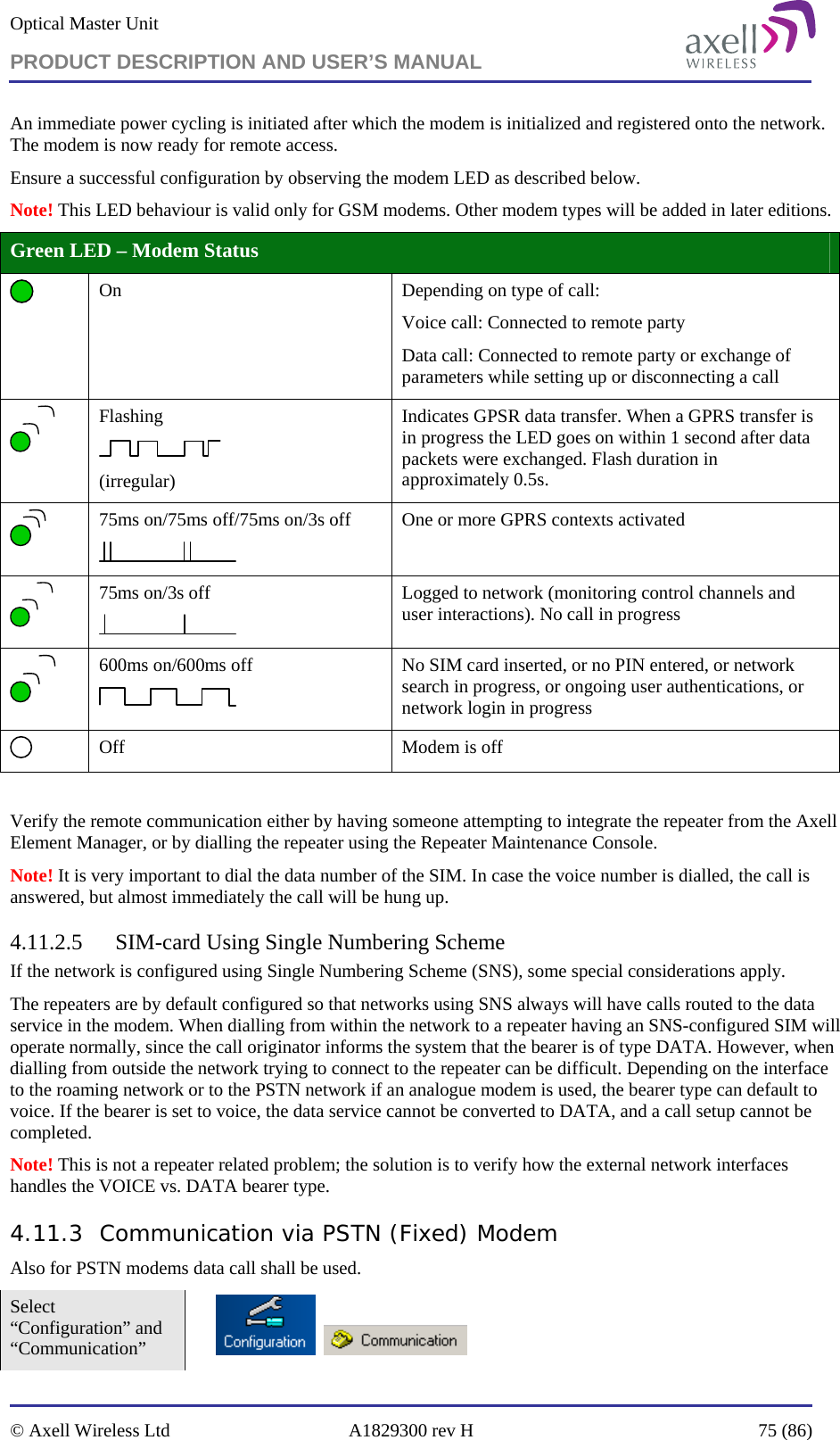
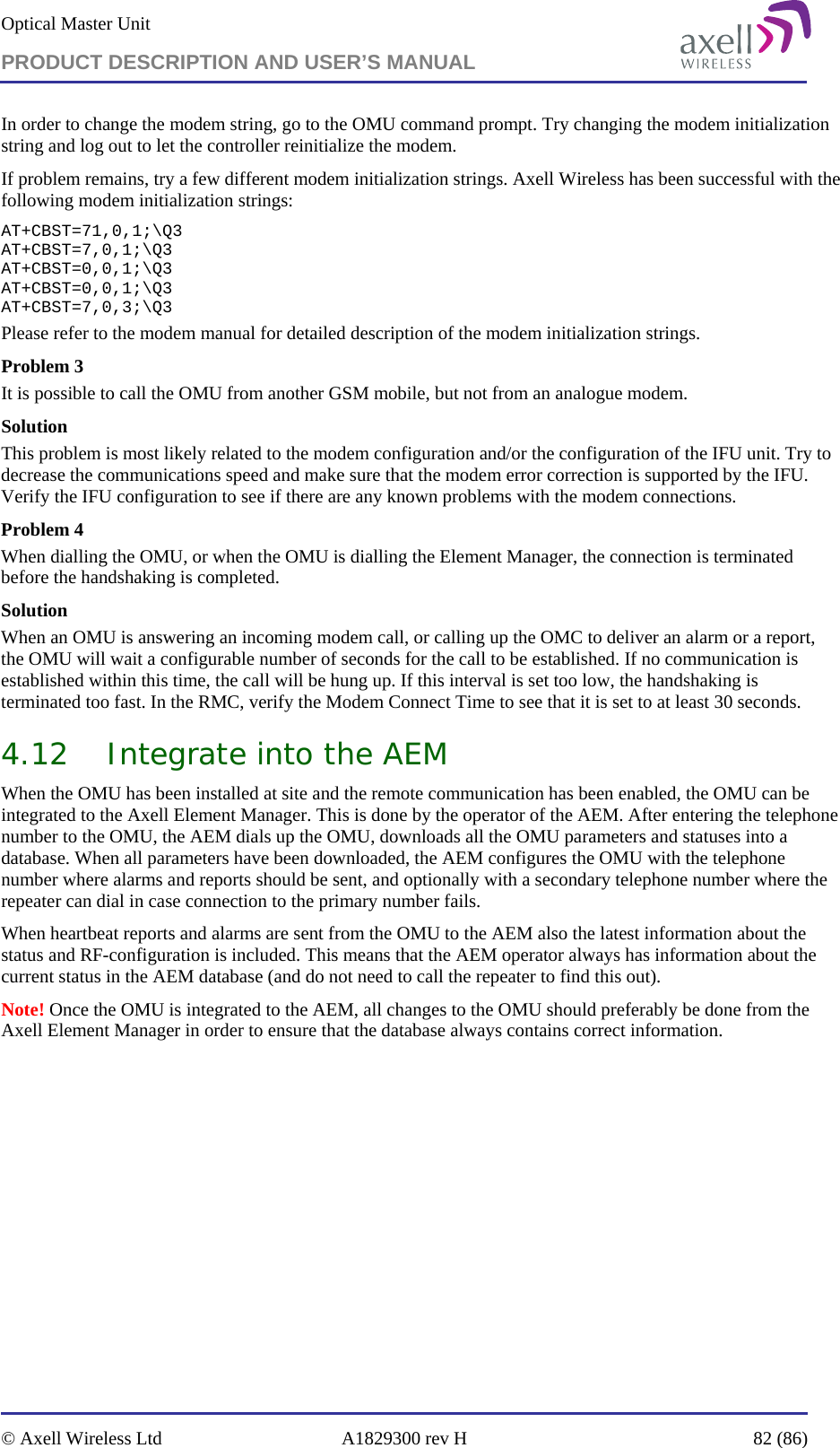
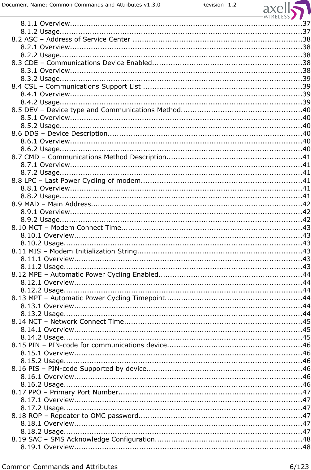
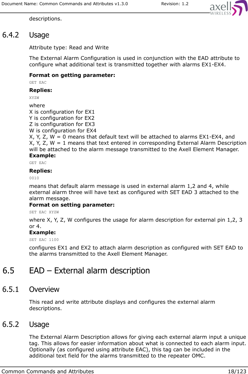
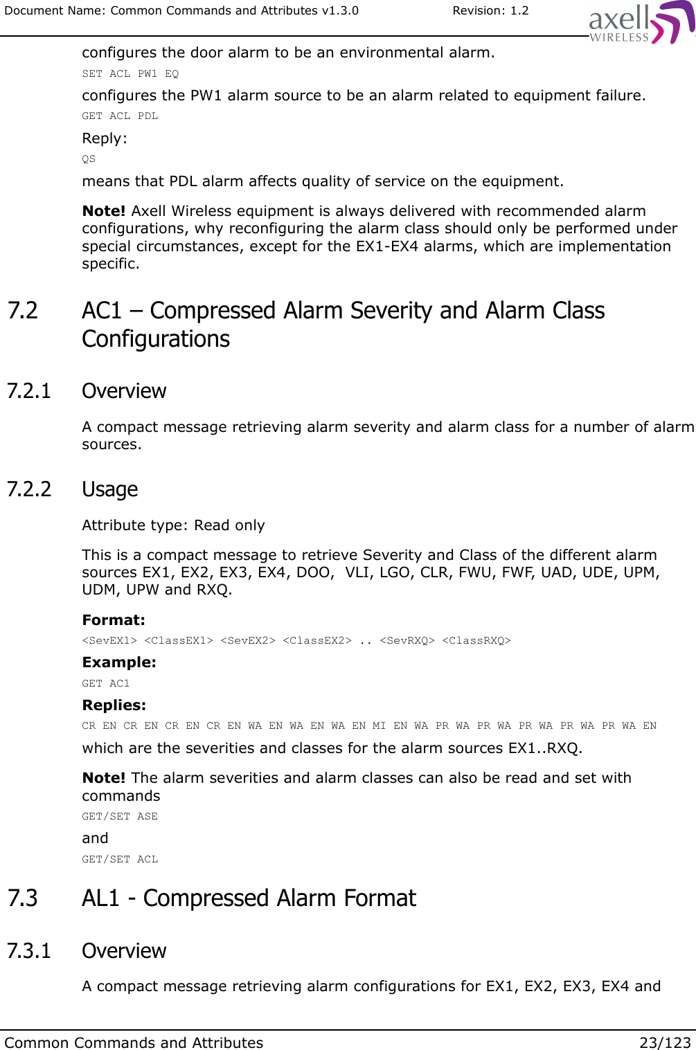
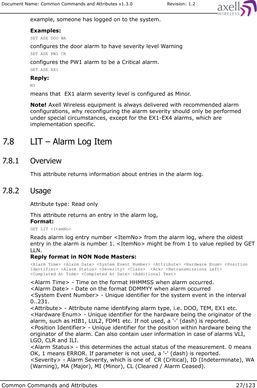
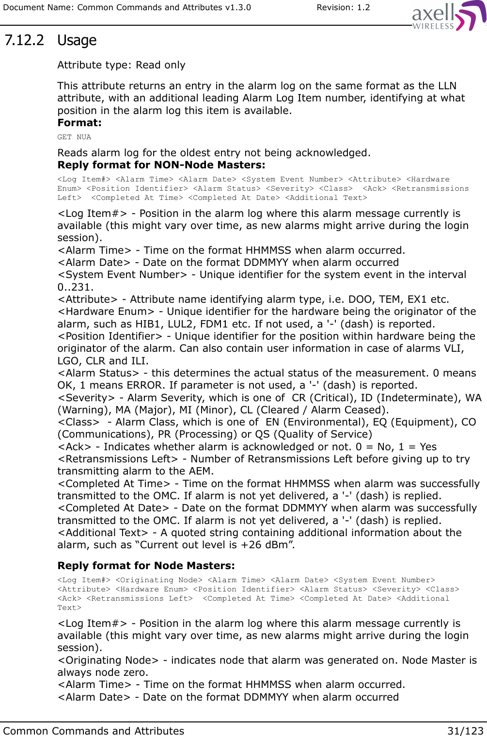
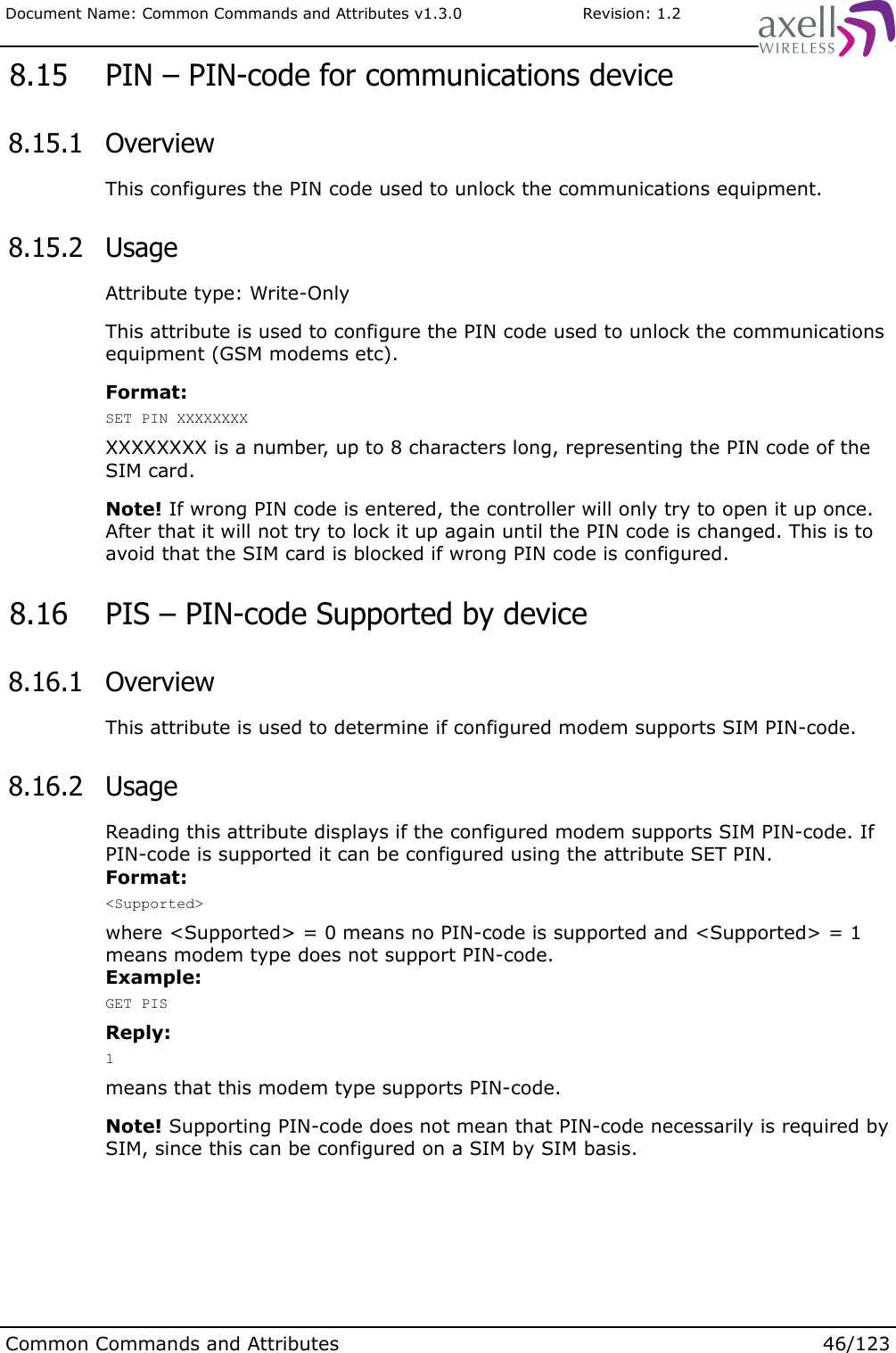
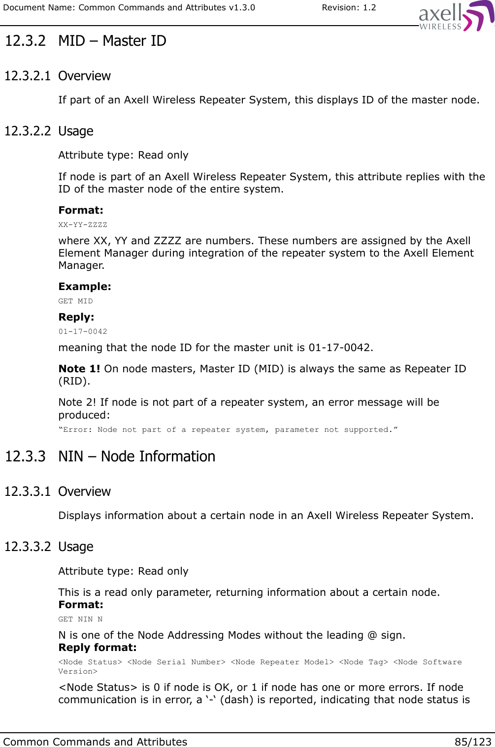
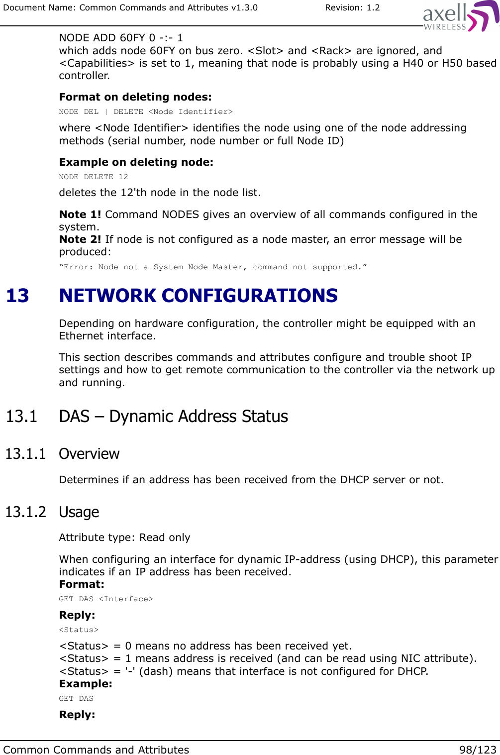
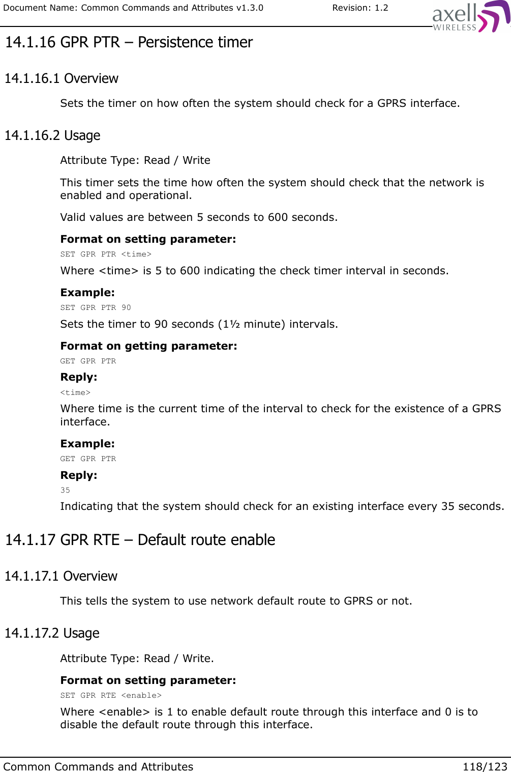
![Document Name: Common Commands and Attributes v1.3.0 Revision: 1.2 8.27.2 UsageWhen typing ACCESS MODEM, the controller will send all the characters typed directly out the modem port. All characters replied back from the modem will be presented directly to the user. This command is useful for advanced remote communication trouble shooting issues.Format:ACCESS MODEM [-B Baud Rate]where the optional switch -B allows to connect to the modem using any of the standard baud rates 1200, 2400, 4800, 9600, 19200, 38400, 57600, 115200 or 230400.Using other baud rates than the default will only work if modem is configured for this speed or is using auto bauding.If the modem is busy dialing to the Axell Element Manager, or if someone is logged in remotely to the repeater, the controller will attempt to access the modem for a limited amount of time before giving up. This might also happen if the controller is busy initializing the modem. If this is the case, it is normally possible to access the modem again after a short while.To abort an ACCESS MODEM session, press three ‘-‘ in a row (all three within one second) to come back to the repeater command prompt.Note 1! When accessing the modem port the modem might be configured with “echo off”, meaning that the characters entered will not be echoed back to the screen. In order to enable “echo”, press Enter. After that, typeATE1(invisible), followed by Enter. The modem should then reply withOKindicating that the echo is enabled. All characters entered will now be echoed back to the user.Note 2! Command will not work when logged in to the controller remotely over the modem connection, since modem is busy communicating. 8.28 MODEM 8.28.1 OverviewThis command gives an overview of the actual modem settings. 8.28.2 UsageBy launching the command MODEM, all modem configuration settings are displayed.Common Commands and Attributes 53/123](https://usermanual.wiki/PBE-Europe-as-Axell-Wireless/A207SERIES/User-Guide-1216782-Page-147.png)
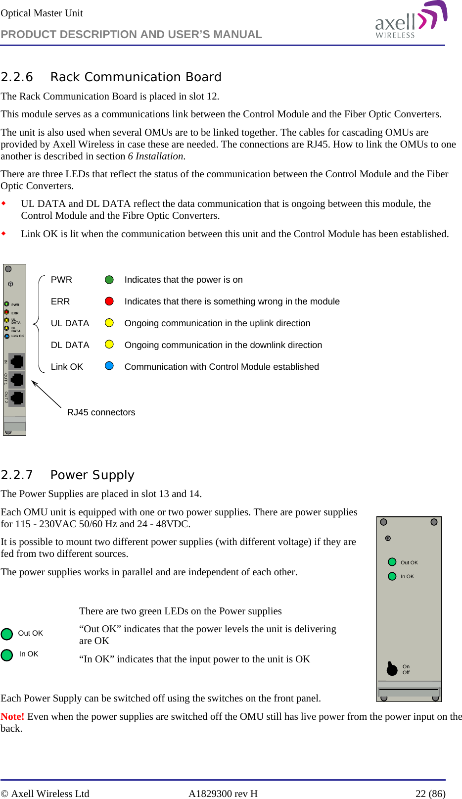
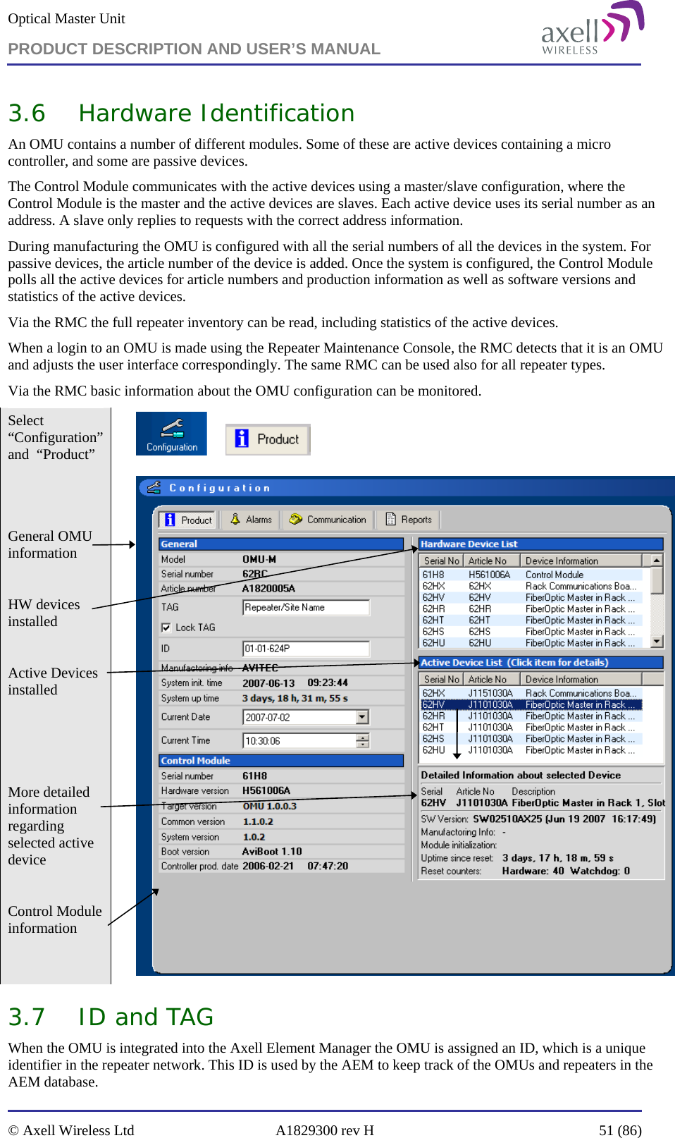
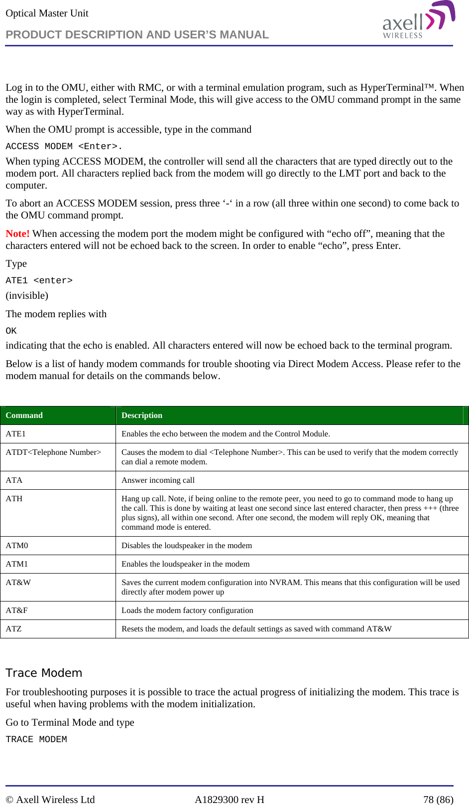
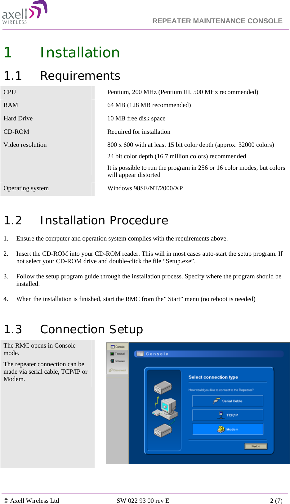
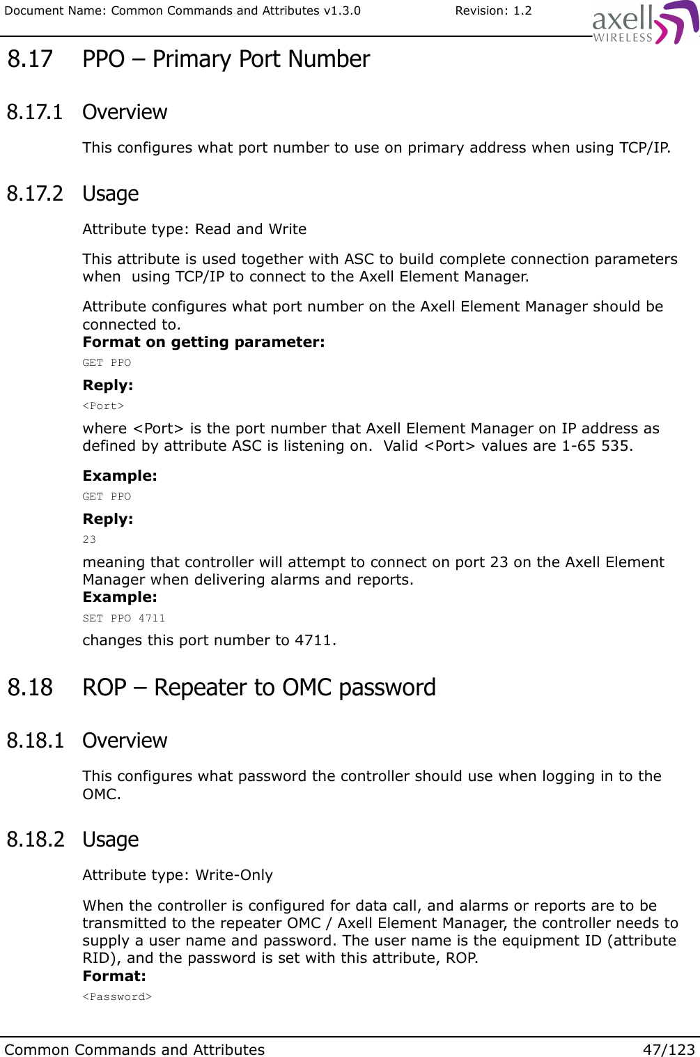
![Document Name: Common Commands and Attributes v1.3.0 Revision: 1.23meaning that there are 3 user accounts currently configured in the system, not including the useradmin and omcuname accounts. 11.5 UAI - User Account Item 11.5.1 OverviewThis gives information about a certain user account in the system, including access level. 11.5.2 UsageReading the User Account Items it is possible to get information about all users added to the system. Format:GET UAI <ItemNo>reads user account entry number <ItemNo> from the user account list, where first account is 1. <ItemNo> might be from 1 to value replied by GET UAC.Reply format:<User Name> <Access Level>where <User Name> is the login username and <Access Level> replies ReadOnly or ReadWrite, depending on user previleges.Note! If no log entry exists in log at this position, a single '-' (dash) is replied.Example:GET UAI 5Reply:Arthur ReadWritewhich means that user Arthur has ReadWrite access to the system. 11.6 ACT USERADD 11.6.1 OverviewThis attribute is used to add users to the system. 11.6.2 UsageAttribute type: Write-Only ActionThis attribute is used to add a user to the system. Only users “useradmin” and “omcuname” are allowed to administer users on the system. Any other user will be prompted for the “useradmin” password when launchingACT USERADD. The system has an upper limit for how many user accounts can be added to the system. Please refer to attribute MNU (Max Number of Users) for details. Format:ACT USERADD [-rw] <user name>Common Commands and Attributes 77/123](https://usermanual.wiki/PBE-Europe-as-Axell-Wireless/A207SERIES/User-Guide-1216782-Page-171.png)
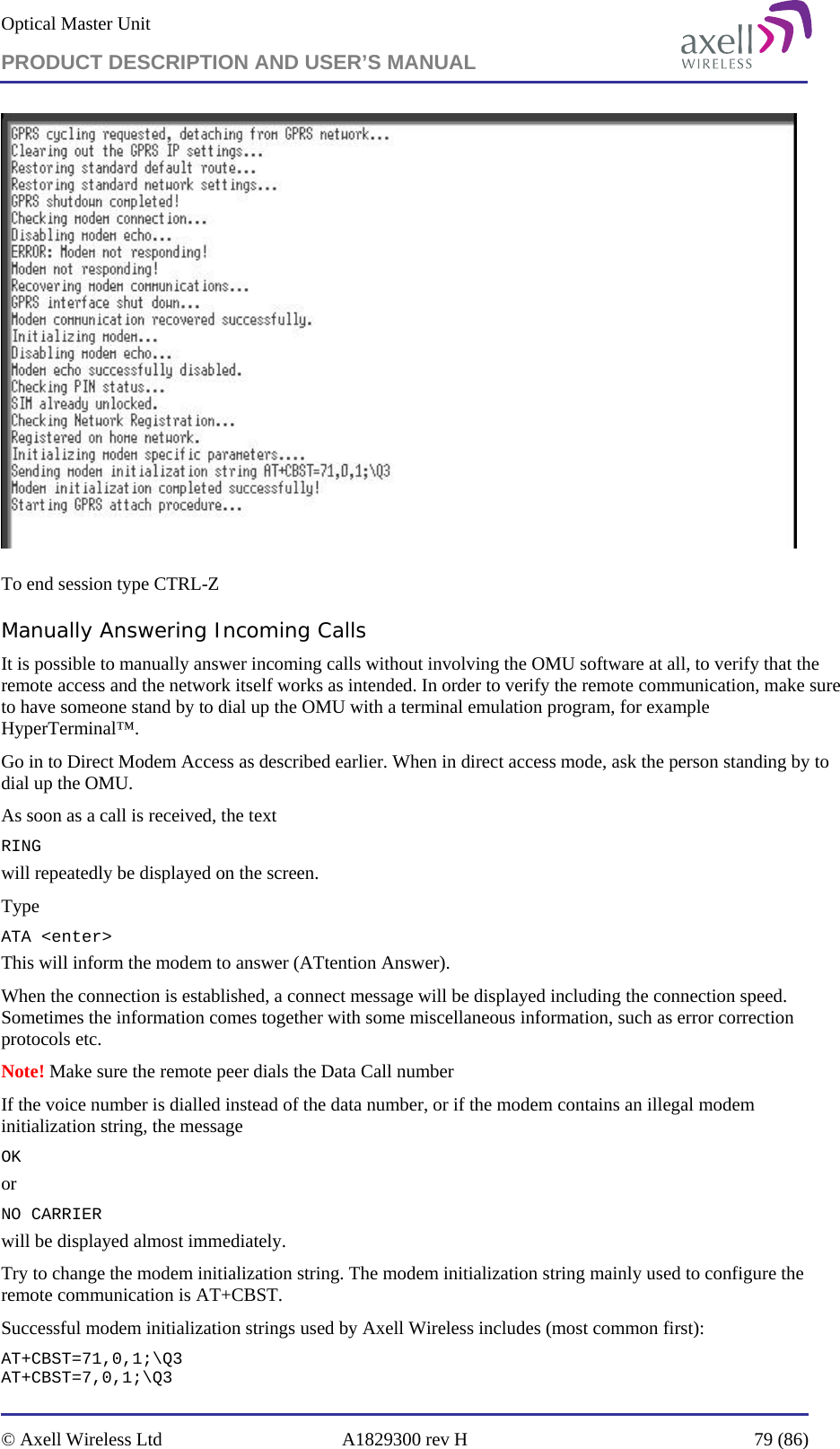
![Document Name: Common Commands and Attributes v1.3.0 Revision: 1.2where <user name> must be at least 6 characters long. <user name> is case sensitive, meaning that it is important to differ between upper and lowercase.Valid user names follow these rules:* First character must be a letter (a-z, A-Z)* Allowed characters in the rest of the user name are a-z, A-Z, 0-9 and special characters '-' (dash), '_' (underscore) and '.' (dot).* Length of user name must be from 6 is 32 characters.If command switch -rw is used, the user will be added with read and write access, otherwise user will be added with read-only access. In order to escalate user to read and write access at a later stage, use ACT USERPROMOTE. [user name].Example 1 , user is not useradmin:AVITEC AB> ACT USERADD MarvinPassword: *********User Marvin added.AVITEC AB>Example 2, user is useradmin (see USERADMIN command for details):USERADMIN> ACT USERADD MarvinError: User already exists.USERADMIN> ACT USERADD ZaphodUser Zaphod added.USERADMIN>Note 1! When adding the user to the system, the password is not set, and the user cannot login. In order to activate the account, use command ACT PASSWORD.Note 2! Adding a user to the system will cause an alarm to be posted to the Axell Element Manager informing about this new user (except for when omcuname adds the user). 11.7 ACT USERDEL 11.7.1 OverviewThis attribute is used to delete a current user from the system. 11.7.2 UsageAttribute type: Write-Only ActionOnly users “useradmin” and “omcuname” are allowed to administer users on the system. Any other user will be prompted for the “useradmin” password when launching ACT USERDEL.Format:ACT USERDEL <user name>where <user name> is one of the users in the system. <user name> is case sensitive, meaning that the system differs between uppercase and lowercase characters.Users currently logged in to the system cannot be deleted.Note! Users omcuname and useradmin cannot be deleted from the system. Example 1 , user is not useradmin:AVITEC AB> ACT USERDEL TrillianPassword: *********User Trillian deleted.AVITEC AB>Common Commands and Attributes 78/123](https://usermanual.wiki/PBE-Europe-as-Axell-Wireless/A207SERIES/User-Guide-1216782-Page-172.png)
![Document Name: Common Commands and Attributes v1.3.0 Revision: 1.2Format on changing other users password:ACT PASSWORD [user name]which will change the password for [user name]. If [user name] is the same as currently logged in user, this will behave in the same way as changing own password.If not being logged in as useradmin, the useradmin password will first be prompted for, after which the password can be changed. Example (assuming user is not useradmin):AVITEC AB> ACT PASSWORD RutgerUser Admin Password: ******New password should be at least 5 characters long, and preferably contain a combination of upper and lower case letters and numbers.Enter new password:Re-enter new password:Password changed.AVITEC AB>Example (user is useradmin):USERADMIN> ACT PASSWORD RutgerNew password should be at least 5 characters long, and preferably contain a combination of upper and lower case letters and numbers.Enter new password:Re-enter new password:Password changed.Note! For user account omcuname, changing passwords have slightly different behavior.Format on changing password when user is omcuname:ACT PASSWORD [user name] [password]This will change password of the [user name] instantly.Example (user is omcuname):AVITEC AB> ACT PASSWORD Rutger Wibba45ResPassword for Rutger changed successfully.AVITEC AB>Note! Changing a user password in the system will cause an alarm to be posted to the Axell Element Manager informing about the changed password. Alarm message will not include the password itself, but only inform about the change (except for when omcuname changes the password). 11.11 USERADMIN 11.11.1 OverviewThis command is used to escalate rights and run the system with useradmin rights. 11.11.2 UsageThis command is used to enter the system in as user administrator. Running the controller with useradmin rights is especially useful when configuring many user accounts in a row to avoid having to enter the useradmin password for each administration task being performed.Format:USERADMINwill prompt the user for the useradmin password.Example:Common Commands and Attributes 81/123](https://usermanual.wiki/PBE-Europe-as-Axell-Wireless/A207SERIES/User-Guide-1216782-Page-175.png)
![Document Name: Common Commands and Attributes v1.3.0 Revision: 1.2 12.2.3 Node ID AddressingNode can also be addressed using the full Node ID.Example:AVITEC AB> @01-01-5S45 GET TAGSITE3_TUNNEL_OPENINGAVITEC AB> 12.3 Master Slave Common Configurations 12.3.1 DNA – Direct Node Access 12.3.1.1 OverviewSets the user interface in direct node access to another node in a repeater system. 12.3.1.2 UsageAttribute type: Write onlyThis attribute is only used in repeaters / elements being a part of an Axell Wireless repeater system (this can be determined with command GET SNI).When many attributes are sent to another node, the user can enter Direct Node Accessing mode, where the node where the user is logged in redirects all commands to another node. This mode is configured by sending the command:SET DNA [Node Address]where node address can be any of the following addressing modes:* Numeric Addressing using the node number, such as @3* Serial Addressing using node serial number, such as @5TTR* Full Node ID Addressing using the complete node ID, such as @01-10-5TTRWhen going into direct node access, the destination address is displayed in the prompt in the same way as they where addressed, for exampleAVITEC AB@5TTR>Leaving the direct access node is done using the SET DNA command with the node address left out, or by entering the command EXIT.AVITEC AB>SET DNA @01-10-5TTRAVITEC AB@01-10-5TTR>GET DOO1AVITEC AB@01-10-5TTR>SET DNAAVITEC AB> Other nodes can still be addressed when using the Direct Node Addressing mode.For example, being at node 3 and having direct node access to node 0, node 5 can still be accessed:AVITEC AB>SET DNA @0AVITEC AB@0>GET ASC+46705008999AVITEC AB@0>@3 GET DOO1AVITEC AB@0>EXITAVITEC AB>Common Commands and Attributes 84/123](https://usermanual.wiki/PBE-Europe-as-Axell-Wireless/A207SERIES/User-Guide-1216782-Page-178.png)
![Document Name: Common Commands and Attributes v1.3.0 Revision: 1.2 12.4.6 ACT SSP – System Slave Pause 12.4.6.1 OverviewThis action causes a temporary stop in accepting packets from node master. 12.4.6.2 UsageAttribute type: Write-Only ActionThis command is used to temporarily stop handling data packets from the node master, and is mainly used for testing purposes.Format:ACT SSP [N]where the optional parameter N determines number of seconds that the interface should pause the remote communications.N is from 1 to 120 seconds. If N is not provided, slave will pause communications for 5 seconds.Example:ACT SSP 12will pause the system slave interface for 12 seconds.Note 1! When executing this command, no communication with other nodes in the network will be possible.Note 2! If node is not part of a repeater system, an error message will be produced:“Error: Node not part of a repeater system, parameter not supported.” 12.4.7 SST – System Slave Statistics 12.4.7.1 OverviewDisplays detailed statistics of the system slave interface. 12.4.7.2 UsageAttribute Type: Read-OnlyThis attribute replies with statistics on the System Slave, and is mainly intended for troubleshooting during system setup.Two different packets can be received by the node, a broadcast, which is sent to all nodes in the system and a data packet, which his intended for a specific node. Broadcasts never requires replies back to the master, while all data packets expects a reply to be transmitted back to the node master (assuming packet destination was this slave node). For each packet received, a number of error checks are performed to see that data packets are not corrupted, such as Checksum Errors and Length Errors.Format:<Rx Bytes> <Tx Bytes> <Rx Broadcast> <Rx Data Packets> <Rx Data to me> <CSUM Errors> Common Commands and Attributes 92/123](https://usermanual.wiki/PBE-Europe-as-Axell-Wireless/A207SERIES/User-Guide-1216782-Page-186.png)
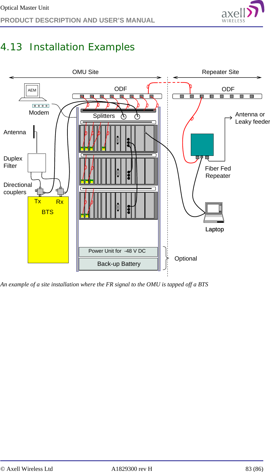
![Document Name: Common Commands and Attributes v1.3.0 Revision: 1.2Avitec ControllerRepeater ID: 01-10-624T1/23/2009 23:43:23login: avitecPassword:You are now logged in to the Avitec Control Module.Time: 23:43:30 Date: 2009-01-23 RID: 01-10-624T Tag: Repeater/Site NameSYSEVENT: User logged in with full accessAVITEC AB>get mdlMBF-S-9-SAVITEC AB>AVITEC AB>exitUser logged out from Control Module.Remote node logged out, aborting.Shutting down connection.Over and out.AVITEC AB>access node 2 12.5.6 NODE 12.5.6.1 OverviewCommand node is used to add or remove nodes from a master slave system, and can only be ran on node masters. 12.5.6.2 Description When setting up a repeater system, the node master needs to have information on all the nodes in the network. By using the node command, nodes can be added to or removed from the repeater system. In order to get an overview of configured nodes in the network, refer to command nodes.Format on adding nodes:NODE ADD <Node Serial> <Bus> <Rack>:<Slot> <Capabilities> [Baud Rate]where<Node Serial> is the serial number of the node (controller or repeater / element serial number) that should be added. Serial Numbers are always exactly four characters long. Letter 'o' is not used (to avoid confusion between letter 'o' and digit zero).<Bus> determines which one of the two data communication channels in the controller that should be used (refer to target documentation for details). Valid values are 0 and 1.<Rack> is used in some targets (such as Optical Master Unit) to specify what communications device is used for communication with remote node. If not used, a '-' (dash) should be entered instead.<Slot> is used in some targets (such as Optical Master Unit) to specify what communications device is used for communication with remote node.<Capabilities> is used to determine what kind of network element is to be monitored. This should be set to 1 for H40/H50-controller based slaves, and 0 for older slave types (H30/H12-controller based).[Baud Rate] is an optional parameter that defines what baud rate to use on communication between node master and actual nodes / slaves. If not supplied, 57600 is assumed. Baud rate is normally configured when adding nodes with <Capabilities> set to 0, where data rate between node master and slaves is lower.Example on adding node:Common Commands and Attributes 97/123](https://usermanual.wiki/PBE-Europe-as-Axell-Wireless/A207SERIES/User-Guide-1216782-Page-191.png)
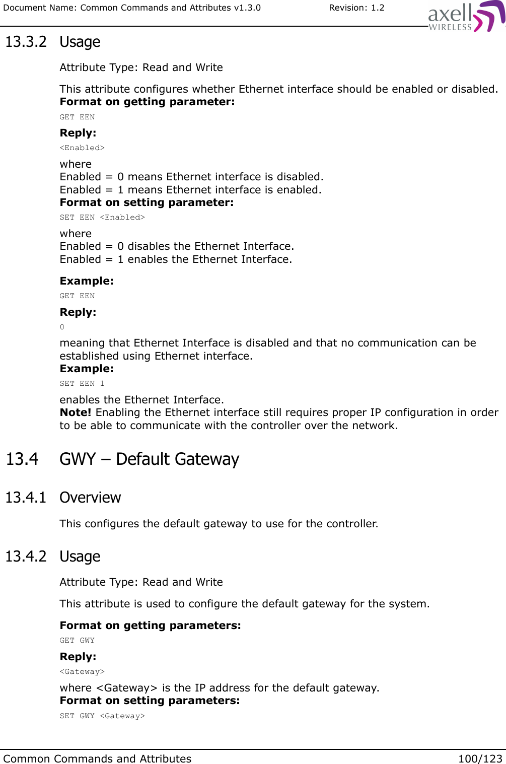
![Document Name: Common Commands and Attributes v1.3.0 Revision: 1.20which means that no address has yet been received from the DHCP server.Note! In order to re-request an IP-address, refer to attribute NRS. 13.2 DNS – DNS Address Configurations 13.2.1 OverviewThis displays and configures the DNS server(s). 13.2.2 UsageAttribute Type: Read and WriteThis attribute is used to read and configure the DNS servers for the controller. Note! If using DHCP for address configuration (as configured using the NIC attribute), the DNS servers are normally supplied from the DHCP server. Format on getting parameters:GET DNSReply:<DNS 1> <DNS 2> ... <DNS N>where<DNS x> is the IP address to the DNS servers.Example:GET DNSReply:192.168.1.45 192.168.1.46which are the IP-addresses for the two configured DNS addresses.Format on setting parameters:SET DNS [DNS 1] [DNS 2] [DNS 3]where[DNS x] are IP-addresses for the DNS servers on the format X.Y.Z.W0<X<255, 0<=Y<=255, 0<=Z<=255, 0<W<255.Up to three different DNS servers can be configured.Example 1:SET DNSclears all DNS server addresses.Example 2:SET DNS 192.168.4.177 192.168.4.178 192.168.4.179configures IP addresses of three DNS servers. 13.3 EEN – Ethernet Enabled 13.3.1 OverviewThis attribute enables or disables the Ethernet Interface.Common Commands and Attributes 99/123](https://usermanual.wiki/PBE-Europe-as-Axell-Wireless/A207SERIES/User-Guide-1216782-Page-193.png)
![Document Name: Common Commands and Attributes v1.3.0 Revision: 1.2 13.12 IFCONFIG 13.12.1 OverviewDisplays an overview of configured network interfaces. 13.12.2 UsageThis command gives an overview of configured interface(s), and can be used for advanced IP trouble shooting.Format:ifconfig [interface]where the optional [interface] is one of the network interfaces in the system. If no parameter is supplied, all interfaces are printed.Example:AVITEC AB> ifconfig eth0eth0 Link encap:Ethernet HWaddr 00:14:B1:01:03:E5 inet addr:126.1.24.131 Bcast:126.255.255.255 Mask:255.255.255.0 UP BROADCAST RUNNING MULTICAST MTU:1500 Metric:1 RX packets:61833 errors:0 dropped:0 overruns:0 frame:0 TX packets:15743 errors:0 dropped:0 overruns:0 carrier:0 collisions:0 txqueuelen:100 RX bytes:0 (0.0 B) TX bytes:0 (0.0 B) Interrupt:24 Base address:0xc000AVITEC AB> 13.13 PING 13.13.1 OverviewTool to verify that communications path to remote peer is operational. 13.13.2 UsageThis command is used to ping (send an ICMP packet) to other addresses, and can be used during connection troubleshooting. For example, successfully pinging the configured IP address of the Axell Element Manager is a good way of knowing that communication between controller and AEM is set up correctly, and that the AEM hardware is up and running.Format:ping [-c Count] <destination>where <destination> is either the IP address or the host name to ping. The optional parameter -c can be used to provide number of pings. Note! If parameter -c is not provided, ping will proceed until Ctrl-C is pressed.Example:AVITEC AB> ping -c 5 192.168.1.42Pinging 192.168.1.42 5 times. Press <Ctrl-C> to abort.PING 192.168.1.42 (192.168.1.42): 56 data bytes64 bytes from 192.168.1.42: icmp_seq=0 ttl=64 time=1.4 ms64 bytes from 192.168.1.42: icmp_seq=1 ttl=64 time=0.9 ms64 bytes from 192.168.1.42: icmp_seq=2 ttl=64 time=0.9 ms64 bytes from 192.168.1.42: icmp_seq=3 ttl=64 time=0.9 ms64 bytes from 192.168.1.42: icmp_seq=4 ttl=64 time=0.8 ms--- 192.168.1.42 ping statistics ---Common Commands and Attributes 106/123](https://usermanual.wiki/PBE-Europe-as-Axell-Wireless/A207SERIES/User-Guide-1216782-Page-200.png)
![Document Name: Common Commands and Attributes v1.3.0 Revision: 1.2 14.1.1.2 UsageAttribute Type: Read / WriteThe addresses may be given in dotted quad notation or as hostnames that are looked up with the resolver. Usage for setting parameter:SET GPR AAD <address1> [<address2> ... <addressN>]This will sett the acceptable address list to the addresses indicated. To allow ANY address use an asterisk instead “*”.Example:SET GPR AAD 126.1.24.1 126.1.24.2Sets the accebable addresses to 126.1.24.1 and 126.1.24.2.Usage for getting parameter :GET GPR AADReply:126.1.24.1 126.1.24.2Indicating the acceptable addresses set. 14.1.2 GPR ACL – Authorization Client 14.1.2.1 OverviewControls the client authorization parameter. 14.1.2.2 UsageAttribute Type: Read / WriteThis should be the name of the controller if it is used. In most cases an asterisk “*” is used to indicate that ANY name is acceptable. Setting this to the wrong name will make the authentication process to fail.This name is only used in the CHAP/PAP negotiation process. If authorization method is set to None it does not matter.Usage for setting parameter:SET GPR ACL <name>This will set <name> as the client name for the CHAP/PAP negotiationExample:SET GPR ACL voyager.local.systemSets the client name to voyage.local.system.Usage for getting parameter:GET GPR ACLReply:*Indicating that ANY name should be acceptable.Common Commands and Attributes 108/123](https://usermanual.wiki/PBE-Europe-as-Axell-Wireless/A207SERIES/User-Guide-1216782-Page-202.png)
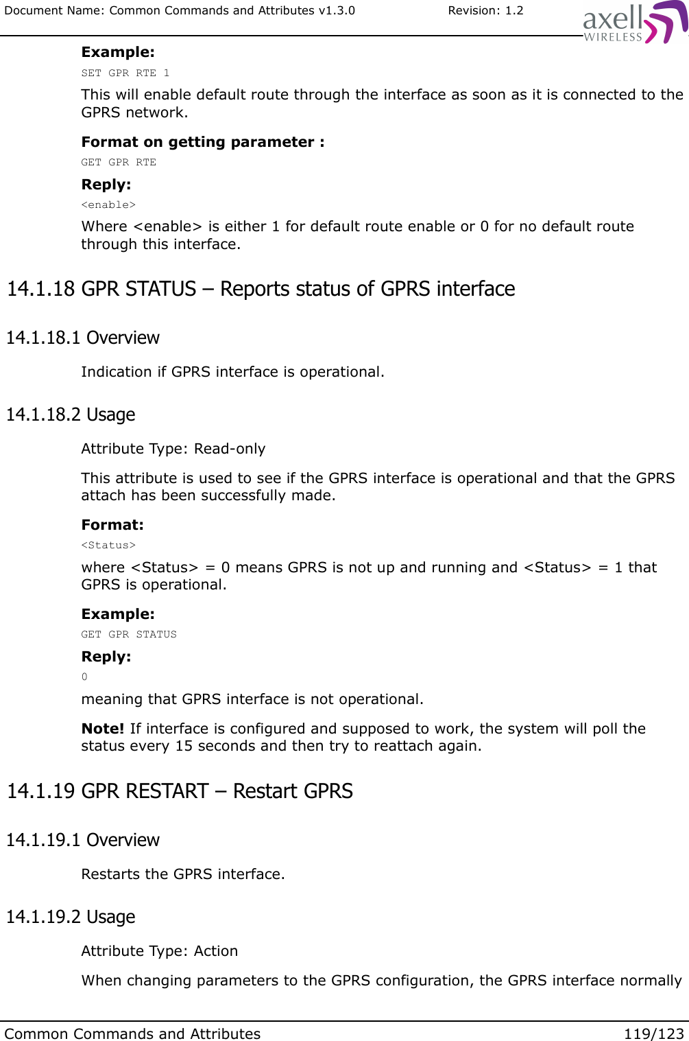
![Document Name: Common Commands and Attributes v1.3.0 Revision: 1.2protocol used is “IP” but in rare cases it may be necessary to change this to “PPP” in order to connect. This information should be given by the network operator.Format on setting the parameter:SET GPR CTY <type>Where <type> can be one of either IP or PPP determining the connection type. Default is IP which should work in most networks.Example:SET GPR CTY IPSets the connection type to “IP”.Format on getting parameter:GET GPR CTYReply:<format>Where format may be either PPP or IP in the reply.Example:GET GPR CTYReply:PPPIndicating that the current method of communicating is PPP. 14.1.11 GPR EXF – GPRS extra flags 14.1.11.1 OverviewThis sets any extra flags for the GPRS negotiations. 14.1.11.2 UsageAttribute Type: Read / Write.If you need this please contact Axell Wireless for more information on the various flags that can be used.Usage for setting parameter :SET GPR EXF [“<flag1> ... <flagN>”]where <flag1> and so on are the various flags.Example:SET GPR EXF noauthWhich will set set use no authorization with the peer when connecting (CHAP/PAP disabled).Usage for getting parameter :GET GPR EXFReply:<flag1 flag2 ... flagN>Returns any flags set or blank if there are none.Common Commands and Attributes 114/123](https://usermanual.wiki/PBE-Europe-as-Axell-Wireless/A207SERIES/User-Guide-1216782-Page-208.png)


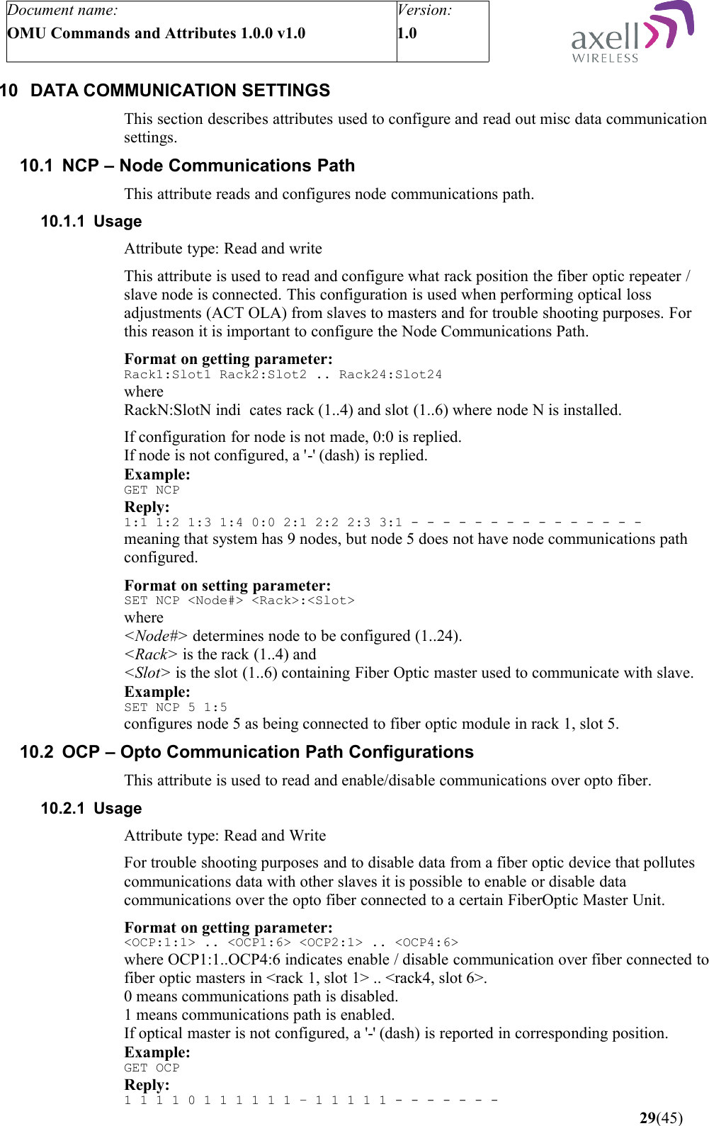
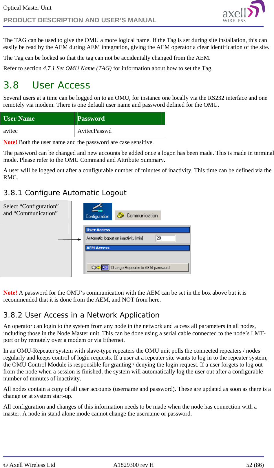
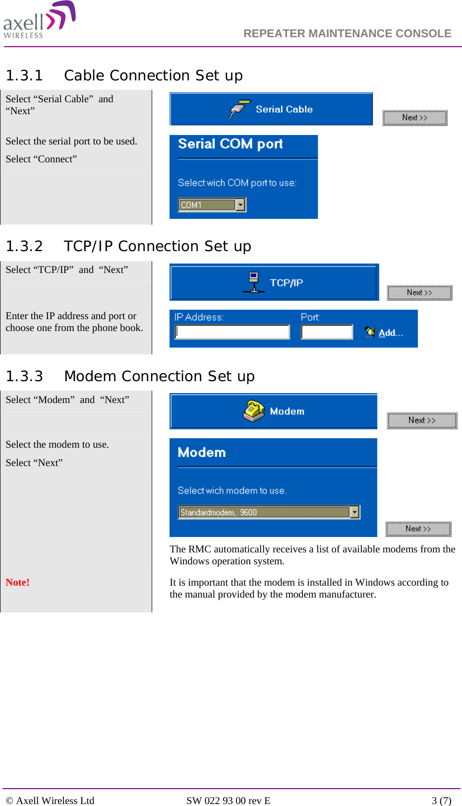
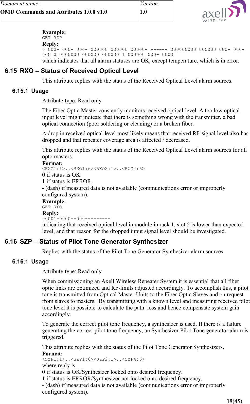
![Document name:OMU Commands and Attributes 1.0.0 v1.0Version:1.0 5 OMU COMMANDS5.1.1 OverviewNODEPNP command is used to automatically identify new nodes in the network.5.1.2 UsageThe OMU communicates with slave repeaters over the optical fibers, and all communication is master/slave based where the OMU is the master polling all slave nodes/FiberOptic repeaters. When communicating with the repeaters, the serial number of the repeater (or repeater controller) is used as an address. This means that the node master must have knowledge of the serial numbers of all repeaters in the network.When adding new nodes in an existing repeater system (or when configuring a new system), nodes are configured using the NODE ADD command, which requires knowledge of the serial number for the installed repeater, and what opto module the fiber is connected to.The NODEPNP command is used to find nodes/repeaters connected to the different fiber optic modules. Older generation of Axell Wireless repeaters (H30 or H12 controllers) do not support NODEPNP, why address needs to be determined at repeater site. Format:NODEPNP [--maxwait <MilliSeconds>] [--reset] [--noack] [--verbose] <Rack>:<Slot>where the following applies:--maxwait - this optional parameter defines number of milliseconds that the node master should wait on reply from the slave nodes (slave nodes wait a random number of milliseconds before replying to a request). If not supplied, 2000 milliseconds will be used. --reset - A node will only reply to PnP requests if node has not been communicated with before. If supplying this flag, all nodes will have the PnP functionality reset, meaning that all nodes will be answering on the request.--noack – when a node is found, the PnP routine will send a message to this node to ensure that it will not answer to the next PnP request. By supplying this optional parameter, no message will be sent, meaning that replies will be made to consecutive requests too.--verbose – by supplying this parameter, progress on the Plug and Play activities will be printed out. This is normally used for advanced trouble shooting.<Rack> is the rack containing the Opto Module performing plug and play for.<Slot> is the slot number within <Rack> to perform plug and play for.Example 1:NODEPNP 1:3Reply:Found node 5644 in rack 1, slot 3.This example showed a successful retrieving of node data. Command NODE ADD 5644 1:3 1 should be used to add node to the system.Example 2:NODEPNP 1:3Reply:No nodes found in rack 1, slot 3. No nodes available, or nodes answered at the same time. You might want to try again.This either means that all nodes already are added, or that other nodes on this slot are of old type not supporting plug and play functionality. 9(45)](https://usermanual.wiki/PBE-Europe-as-Axell-Wireless/A207SERIES/User-Guide-1216782-Page-226.png)
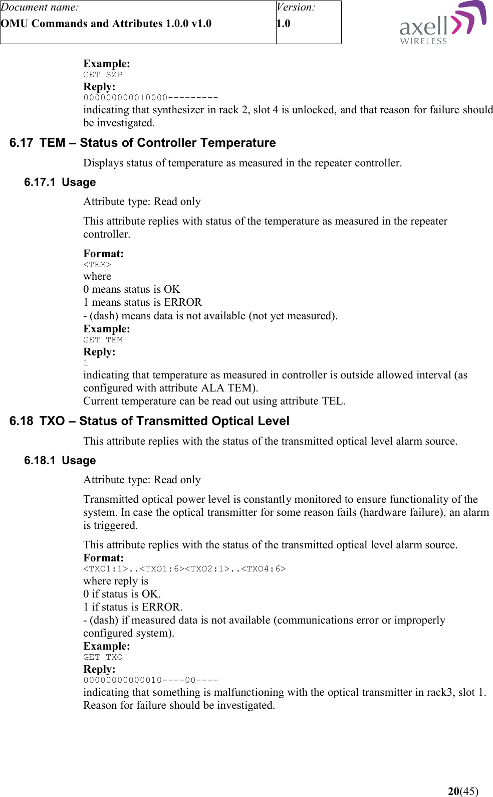
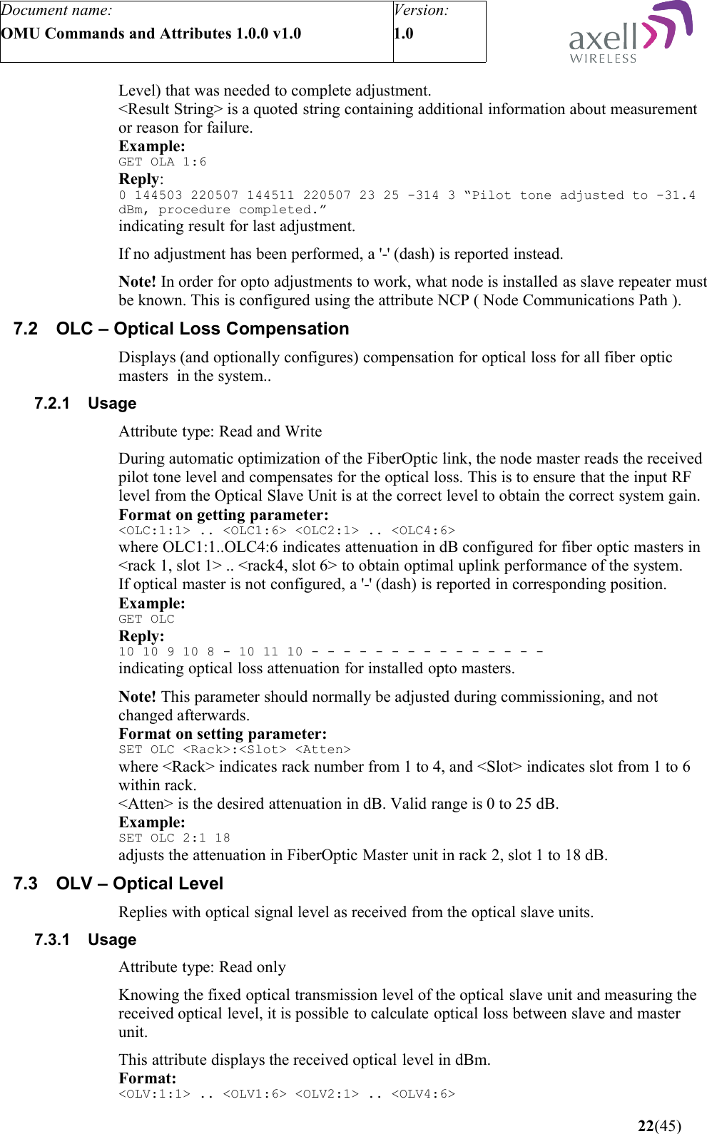
![Document name:OMU Commands and Attributes 1.0.0 v1.0Version:1.0 7 OPTO INTERFACE CONFIGURATIONSThis section describes attributes used to read out and configure settings related to the FiberOptic modules and corresponding pilot tone functionality.7.1 OLA – Optical Loss Adjustment This attribute is used to read and adjust link between master and optical slave unit.7.1.1 UsageAttribute type: Read and ActionThis attribute is used to perform an automatic adjustment of the fiber optic link to compensate for losses, and to read status of last performed adjustment. Adjustments are made to get a well balanced and optimized system, maintaining desired gain over the entire link from input of Optical Master Unit to output of repeater. When performing the adjustment from slave to master, a pilot tone with a well defined level is sent form the slave to the master. To start the measurements, the master must first enable pilot tone signal in the slave (Fiber Optic Slave in repeater), after which pilot tone adjustments can be performed.Once routine is finished, Pilot Tone in slave is disabled againFormat on ACT:ACT OLA <Rack>:<Slot> [-v] [-l]performs automatic adjustment of the opto link from the repeater to the optical master unit in rack <Rack> and <Slot>.If supplying parameter -v (as verbose) progress information is printed out on the screen as the adjustments proceed.If supplying parameter -l (as local) enabling / disabling pilot tone on remote node is disabled. Example:ACT OLA 1:3performs an optical link adjustment of link from repeater to opto module in rack one, slot 3.Reading OLA replies with status of last performed adjustments.Format on GET:GET OLA <Rack>:<Slot> reads last fiber optic adjustment for link from slave repeater to opto module in rack <Rack>, slot <Slot>.Reply:<Status> <Start Time> <Stop Time> <Initial Attenuation> <Resulting Attenuation> <Resulting Pilot Tone Level> <Number of Iterations> <Result String>where<Status> is status of last measurement, 0 means adjustments were successfully completed, 1 means adjustments failed.<Start Time> is on the format HHMMSS DDMMYY, where HHMMSS is the time with 24 hours notation, and DDMMYY is the date for when last measurement started.<Stop Time> is on the format HHMMSS DDMMYY, where HHMMSS is the time with 24 hours notation, and DDMMYY is the date for when last measurement finished.<Initial Attenuation> is the attenuation set before starting the adjustment routine.<Resulting Attenuation> is the attenuation that was set when routine was completed.<Resulting Pilot Tone Level> indicates the received pilot tone level in dBm * 10 when adjustment was completed (for optimal performance, pilot tone should be adjusted to -32.0 dBm).<NumberOfIterations> indicates number of iterations (Set Attenuation- Read Pilot Tone 21(45)](https://usermanual.wiki/PBE-Europe-as-Axell-Wireless/A207SERIES/User-Guide-1216782-Page-238.png)
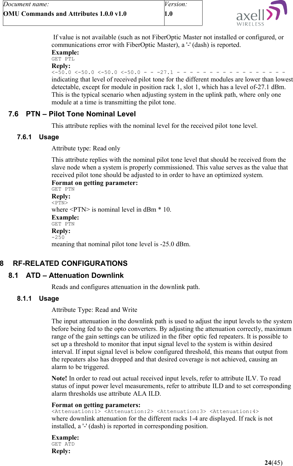
![Document name:OMU Commands and Attributes 1.0.0 v1.0Version:1.0 where OLC1:1..OLC4:6 replies with received optical level in dBm with one decimal resolution for fiber optic masters in <rack 1, slot 1> .. <rack4, slot 6>.If level is lower than lowest detectable, '<[LowDet]' is replied. If value is not available (such as not FiberOptic Master not installed or configured, or communications error with FiberOptic Master), a '-' (dash) is reported.Example:GET OLVReply:-7.1 -7.5 -8.3 -6.2 -6.6 - -11.2 -10.1 - - - - - - - - - - - - - - - -meaning that received optical level is from -6.2 to -11.2 dBm. In this example, knowing that optical transmitted level is 3 dBm, optical loss is varying from 9.2 to to 14.2 dB.7.4 OMP – Opto Master ParametersDisplays different parameters on the optical master.7.4.1 UsageAttribute type: Read onlyThis attribute replies with parameters and constants of the FiberOptic Master. Values are used by the repeater to perform calculations and to present user with opto master performance data.Format:GET OMP <Rack>:<Slot>Reply:<Rx Opto LowDet> <Pilot Offset Attenuation> <Pilot LowDet> <PilotARFCN>where <Rx Opto LowDet> is the lowest detectable received opto signal in dBm with one decimal resolution. <Pilot Offset Attenuation> is a frequency offset in dB set during production of the repeater, and is used to compensate for frequency variations in the opto module.<Pilot LowDet> is the lowest detectable pilot tone level in dBm with one decimal resolution.<PilotARFCN> is the channel used for the pilot tone.Note! If data is not available (communications error with note, or wrong configuration), four dashes separated by space are replied.Example:GET OMP 3:6Reply:-15.0 3 -50.0 500indicating that for fiber optic module in rack 3, slot 6, lowest detectable optical level is -15.0 dBm, pilot tone offset is 3 dB, lowest detectable pilot tone is -50.0 dBm and ARFCN used for generated pilot tone is 500.7.5 PTL – Pilot Tone LevelThis attribute replies with received pilot tone levels from optical slaves.7.5.1 UsageAttribute type: Read onlyThis attribute replies with received pilot tone level from optical slave unit. This value is used during automatic optical loss compensations to ensure that the repeater system is commissioned with optimal performance.Format:<PTL:1:1> .. <PTL1:6> <PTL2:1> .. <PTL4:6>where PTL1:1..PTL4:6 replies with received pilot tone level in dBm with one decimal resolution for fiber optic masters in <rack 1, slot 1> .. <rack4, slot 6>. If lower than lowest detectable pilot tone level, a <[Lowest Detectable Pilot Tone Level] is presented. 23(45)](https://usermanual.wiki/PBE-Europe-as-Axell-Wireless/A207SERIES/User-Guide-1216782-Page-240.png)
![Document name:OMU Commands and Attributes 1.0.0 v1.0Version:1.0 6 6 9 -indicating that rack 1 and 2 have attenuation set to 6 dB, rack three to 9 dB and fourth rack is not configured.Format on setting parameters:SET ATD <Rack K> <Atten X> [<Rack L> <Atten Y>] [<Rack M> <Atten Z>] [<Rack N> <Atten W>]where<Rack K> is the rack selector (1..4) <Attenuation X> is downlink attenuation to set in rack K. Interval is 0 to 21 dB in 3 dB steps. Optionally attenuation in rack L to N can be set at the same time.Example:SET ATD 2 9 3 9sets attenuation in rack 2 and 3 to 9 dB.8.2 ATU – Attenuation UplinkReads and configures the attenuation in the uplink path.8.2.1 UsageAttribute Type: Read and WriteThe attenuation in the uplink path is used to configure the system according to downlink gain settings to get a well balanced system. The attenuation is set in the combiner board.Format on getting parameters:<Attenuation:1> <Attenuation:2> <Attenuation:3> <Attenuation:4>where uplink attenuation for the different racks 1-4 are displayed. If rack is not installed, a '-' (dash) is reported in corresponding position.Example:GET ATUReply:9 9 12 -indicating that rack 1 and 2 have attenuation set to 9 dB, rack three to 12 dB and fourth rack is not configured.Format on setting parameters:SET ATU <Rack K> <Atten X> [<Rack L> <Atten Y>] [<Rack M> <Atten Z>] [<Rack N> <Atten W>]where<Rack K> is the rack selector (1..4) <Attenuation X> is uplink attenuation to set in rack K. Interval is 0 to 21 dB in 3 dB steps. Optionally attenuation in rack L to N can be set at the same time.Example:SET ATU 2 9 3 9sets attenuation in rack 2 and 3 to 9 dB.8.3 ILD – Status of Input Level DownlinkDisplays status of the input power level in the downlink.8.3.1 UsageAttribute Type: Read-OnlyThe controller constantly monitors the input signal level to the rack in the downlink path. If input signal level is below configured threshold, this means that output from the repeaters has dropped too and that desired coverage is not achieved. This causes an alarm to be triggered.This attribute is used to read status of the Input Level alarms. 25(45)](https://usermanual.wiki/PBE-Europe-as-Axell-Wireless/A207SERIES/User-Guide-1216782-Page-242.png)